EP3685053B1 - Sicherungselement und verliersicherungssystem - Google Patents
Sicherungselement und verliersicherungssystem Download PDFInfo
- Publication number
- EP3685053B1 EP3685053B1 EP18734444.5A EP18734444A EP3685053B1 EP 3685053 B1 EP3685053 B1 EP 3685053B1 EP 18734444 A EP18734444 A EP 18734444A EP 3685053 B1 EP3685053 B1 EP 3685053B1
- Authority
- EP
- European Patent Office
- Prior art keywords
- lug
- component
- cutout
- section
- tab
- Prior art date
- Legal status (The legal status is an assumption and is not a legal conclusion. Google has not performed a legal analysis and makes no representation as to the accuracy of the status listed.)
- Active
Links
Images



Classifications
-
- B—PERFORMING OPERATIONS; TRANSPORTING
- B61—RAILWAYS
- B61D—BODY DETAILS OR KINDS OF RAILWAY VEHICLES
- B61D17/00—Construction details of vehicle bodies
-
- B—PERFORMING OPERATIONS; TRANSPORTING
- B61—RAILWAYS
- B61F—RAIL VEHICLE SUSPENSIONS, e.g. UNDERFRAMES, BOGIES OR ARRANGEMENTS OF WHEEL AXLES; RAIL VEHICLES FOR USE ON TRACKS OF DIFFERENT WIDTH; PREVENTING DERAILING OF RAIL VEHICLES; WHEEL GUARDS, OBSTRUCTION REMOVERS OR THE LIKE FOR RAIL VEHICLES
- B61F99/00—Subject matter not provided for in other groups of this subclass
-
- B—PERFORMING OPERATIONS; TRANSPORTING
- B61—RAILWAYS
- B61F—RAIL VEHICLE SUSPENSIONS, e.g. UNDERFRAMES, BOGIES OR ARRANGEMENTS OF WHEEL AXLES; RAIL VEHICLES FOR USE ON TRACKS OF DIFFERENT WIDTH; PREVENTING DERAILING OF RAIL VEHICLES; WHEEL GUARDS, OBSTRUCTION REMOVERS OR THE LIKE FOR RAIL VEHICLES
- B61F1/00—Underframes
-
- F—MECHANICAL ENGINEERING; LIGHTING; HEATING; WEAPONS; BLASTING
- F16—ENGINEERING ELEMENTS AND UNITS; GENERAL MEASURES FOR PRODUCING AND MAINTAINING EFFECTIVE FUNCTIONING OF MACHINES OR INSTALLATIONS; THERMAL INSULATION IN GENERAL
- F16B—DEVICES FOR FASTENING OR SECURING CONSTRUCTIONAL ELEMENTS OR MACHINE PARTS TOGETHER, e.g. NAILS, BOLTS, CIRCLIPS, CLAMPS, CLIPS OR WEDGES; JOINTS OR JOINTING
- F16B39/00—Locking of screws, bolts or nuts
- F16B39/02—Locking of screws, bolts or nuts in which the locking takes place after screwing down
-
- F—MECHANICAL ENGINEERING; LIGHTING; HEATING; WEAPONS; BLASTING
- F16—ENGINEERING ELEMENTS AND UNITS; GENERAL MEASURES FOR PRODUCING AND MAINTAINING EFFECTIVE FUNCTIONING OF MACHINES OR INSTALLATIONS; THERMAL INSULATION IN GENERAL
- F16B—DEVICES FOR FASTENING OR SECURING CONSTRUCTIONAL ELEMENTS OR MACHINE PARTS TOGETHER, e.g. NAILS, BOLTS, CIRCLIPS, CLAMPS, CLIPS OR WEDGES; JOINTS OR JOINTING
- F16B5/00—Joining sheets or plates, e.g. panels, to one another or to strips or bars parallel to them
- F16B5/02—Joining sheets or plates, e.g. panels, to one another or to strips or bars parallel to them by means of fastening members using screw-thread
-
- F—MECHANICAL ENGINEERING; LIGHTING; HEATING; WEAPONS; BLASTING
- F16—ENGINEERING ELEMENTS AND UNITS; GENERAL MEASURES FOR PRODUCING AND MAINTAINING EFFECTIVE FUNCTIONING OF MACHINES OR INSTALLATIONS; THERMAL INSULATION IN GENERAL
- F16B—DEVICES FOR FASTENING OR SECURING CONSTRUCTIONAL ELEMENTS OR MACHINE PARTS TOGETHER, e.g. NAILS, BOLTS, CIRCLIPS, CLAMPS, CLIPS OR WEDGES; JOINTS OR JOINTING
- F16B5/00—Joining sheets or plates, e.g. panels, to one another or to strips or bars parallel to them
- F16B5/06—Joining sheets or plates, e.g. panels, to one another or to strips or bars parallel to them by means of clamps or clips
-
- F—MECHANICAL ENGINEERING; LIGHTING; HEATING; WEAPONS; BLASTING
- F16—ENGINEERING ELEMENTS AND UNITS; GENERAL MEASURES FOR PRODUCING AND MAINTAINING EFFECTIVE FUNCTIONING OF MACHINES OR INSTALLATIONS; THERMAL INSULATION IN GENERAL
- F16B—DEVICES FOR FASTENING OR SECURING CONSTRUCTIONAL ELEMENTS OR MACHINE PARTS TOGETHER, e.g. NAILS, BOLTS, CIRCLIPS, CLAMPS, CLIPS OR WEDGES; JOINTS OR JOINTING
- F16B5/00—Joining sheets or plates, e.g. panels, to one another or to strips or bars parallel to them
- F16B5/06—Joining sheets or plates, e.g. panels, to one another or to strips or bars parallel to them by means of clamps or clips
- F16B5/0607—Joining sheets or plates, e.g. panels, to one another or to strips or bars parallel to them by means of clamps or clips joining sheets or plates to each other
- F16B5/0621—Joining sheets or plates, e.g. panels, to one another or to strips or bars parallel to them by means of clamps or clips joining sheets or plates to each other in parallel relationship
- F16B5/0635—Joining sheets or plates, e.g. panels, to one another or to strips or bars parallel to them by means of clamps or clips joining sheets or plates to each other in parallel relationship fastened over the edges of the sheets or plates
-
- F—MECHANICAL ENGINEERING; LIGHTING; HEATING; WEAPONS; BLASTING
- F16—ENGINEERING ELEMENTS AND UNITS; GENERAL MEASURES FOR PRODUCING AND MAINTAINING EFFECTIVE FUNCTIONING OF MACHINES OR INSTALLATIONS; THERMAL INSULATION IN GENERAL
- F16B—DEVICES FOR FASTENING OR SECURING CONSTRUCTIONAL ELEMENTS OR MACHINE PARTS TOGETHER, e.g. NAILS, BOLTS, CIRCLIPS, CLAMPS, CLIPS OR WEDGES; JOINTS OR JOINTING
- F16B5/00—Joining sheets or plates, e.g. panels, to one another or to strips or bars parallel to them
- F16B5/06—Joining sheets or plates, e.g. panels, to one another or to strips or bars parallel to them by means of clamps or clips
- F16B5/0607—Joining sheets or plates, e.g. panels, to one another or to strips or bars parallel to them by means of clamps or clips joining sheets or plates to each other
- F16B5/0621—Joining sheets or plates, e.g. panels, to one another or to strips or bars parallel to them by means of clamps or clips joining sheets or plates to each other in parallel relationship
- F16B5/0642—Joining sheets or plates, e.g. panels, to one another or to strips or bars parallel to them by means of clamps or clips joining sheets or plates to each other in parallel relationship the plates being arranged one on top of the other and in full close contact with each other
Definitions
- the present invention relates to a loss protection system with a securing element for securing components of a rail vehicle.
- a securing element with horizontally arranged bolts secured on both sides between a car body structure and a component to be attached is known from the prior art.
- One object of the present invention is to provide an improved securing element for securing components of a vehicle, in particular a rail vehicle, and a loss safeguarding system with at least one securing element and a secured component.
- a securing element for securing components of a vehicle, in particular a rail vehicle, has a first section, a first tab and a second tab.
- the first section is in the form of an elongated plate and extends in a first plane. At least one first through opening is arranged in the first section. The first through opening is designed to receive a first releasable connection for fastening the securing element to a first component, at least in sections.
- the first section has a long side.
- the first tab and the second tab are arranged opposite one another on the long side of the first section and protrude from the first plane onto a common side of the first section.
- the first tab is designed to rest on the top of the first component.
- the second bracket is designed to support a second component on the underside and to secure it against falling.
- This embodiment has the advantage that a simple and reliable protection against loss can be provided which, in particular when the second component is fastened to the first component by means of a screw connection subject to tensile stress, in the event of failure of the screw connection, the second component, which is on the underside of the The first component is arranged, thereby preventing the first tab from resting on the top of the first component, while the second component is resting on the top of the second tab.
- the securing element is also particularly simple and inexpensive to manufacture and can be easily assembled by just one person.
- the first tab has a first recess.
- the first recess is designed to receive the first component at least in sections.
- the first tab is connected by a first fixed end to the long side of the first section.
- the first recess is arranged on a side of the first tab facing the second tab and is open towards the second tab.
- the first recess is arranged adjacent to the fixed end and is preferably designed in the form of a slot. This configuration has the advantage that in the assembled state the the first component can engage in the first recess, whereby the securing element can be prevented from slipping in at least one spatial direction.
- the securing element can be displaced along the first component in a second spatial direction. This enables simple positioning of the second component relative to the first component and of the securing element relative to the first component.
- the second tab has a second recess.
- the second recess is designed to receive the second component at least in sections.
- the second tab is connected to the long side of the first section by a second fixed end.
- the second recess is disposed adjacent the second fixed end.
- the second recess is preferably designed in the shape of a slot.
- the second recess is arranged on a side of the second tab facing the first tab and is open towards the first tab.
- the second component can engage at least in sections in the second recess, thereby preventing the second component from slipping. As a result, the second component rests securely on the second tab.
- the first tab has a first tab area and a first curved area.
- the second tab has a second tab area and a second arch area.
- the first and second tab areas are plate-shaped.
- the first tab area extends in a second plane.
- the second tab area extends in a third plane.
- the second and the third plane are each arranged in a first direction parallel to the first section and inclined in a second direction, preferably perpendicular, to the first section.
- the first tab area adjoins a first free end.
- the second tab area adjoins a second free end.
- the first arch area connects the first tab area with the first section.
- the second arch area connects the second tab area with the first section.
- the second plane overlaps and the third plane or the second plane is formed parallel to the third plane.
- the securing element has a second section and a third section.
- the second section and the third section are each formed in the form of an elongated plate.
- the second section and the third section extend in the first plane.
- the third section and the first section are arranged offset from one another.
- the second section is inclined, preferably perpendicular, to the first section and / or to the third section.
- the second section is arranged between the first section and the third section and connects the first section to the third section.
- the third section is arranged parallel to the first section.
- the securing element also has a third tab and a fourth tab.
- the third section has a long side.
- the third flap and the fourth flap are arranged opposite one another on the long side of the third section and protrude from the first plane on a common side of the third section and on the same side as the first and second flaps.
- the third tab is designed to rest on the top of the first component.
- the fourth tab is designed to support the second component on the underside and to secure it against falling. As a result, the securing element can absorb particularly high supporting forces.
- the third section has at least one second through opening.
- the second through opening is designed to receive a second releasable connection for fastening the securing element to the first component, at least in sections.
- the securing element can be connected to the first component in a rotationally secure manner by a second releasable connection.
- the third tab has a third recess and / or the fourth tab has a fourth recess.
- the third tab is connected to a third fixed end and the fourth tab is connected to the long side of the third section by a fourth fixed end.
- the third recess is designed to receive the first component at least in sections and / or the fourth recess is designed to receive the second component at least in sections.
- the third recess is arranged adjacent to the third fixed end of the third tab and / or the fourth recess is arranged adjacent to the fourth fixed end of the fourth tab.
- the third recess is arranged on a side of the third tab facing the fourth tab and is open to the fourth tab and / or the fourth recess is arranged on a side of the fourth tab facing the third tab and is open to the third tab.
- the third tab extends in sections in a fourth plane and the fourth tab in sections in a fifth plane.
- the second level and the fourth level and / or the third level and the fifth level are arranged parallel to one another.
- the third tab and / or the fourth tab are arranged on a side of the third section facing the first section and the first tab and / or the second tab are arranged on a side of the first section facing the third section.
- the third tab and / or the fourth tab are arranged on a side of the third section facing away from the first section and the first tab and / or the second tab are arranged on a side of the first section facing away from the third section.
- a loss protection system preferably a rail vehicle, has at least one securing element, a first component and a second component and at least one first detachable connection and a third detachable connection.
- the first releasable connection engages through the first through opening and attaches the securing element to the first component.
- the third releasable connection connects the first component with the second component under tension.
- the first component and the second component are arranged at least in sections between the first tab and the second tab. In the event of failure and / or loosening of the third releasable connection, the second component rests on the second tab and the second tab secures the second component from falling. In the event of failure and / or loosening of the first releasable connection, the first tab rests on the first component and holds the securing element on the first component.
- the first component has a first engagement section.
- the first engagement portion is aligned parallel to the first portion.
- the first engagement portion engages in the first recess.
- a first stop surface of the first engagement section which is arranged at a free end of the first engagement section, rests on a base of the first recess.
- the second component has a second engagement section.
- the second engagement portion is aligned parallel to the first portion and extends in an opposite direction to the first engagement portion.
- the second engagement portion engages in the second recess.
- a second stop surface of the second engagement section which is arranged at a free end of the second engagement section, rests on a base of the second recess. This reliably prevents the securing element from slipping off the components in the partially assembled state.
- FIG 1 shows a three-dimensional view of a section of a rail vehicle designed as a loss protection system 2 with a securing element 1, a first component 141 and a second component 142.
- the first component 141 can be a sandpit, for example.
- Sandboxes are typically installed in the underfloor area of rail vehicles, with the sand being used to increase the friction in the event of an emergency braking of the rail vehicle.
- the second component 142 can be a sandpit cover, for example.
- the second component 142 is arranged on the underside of the first component 141.
- the first component 141 and / or the second component 142 can be another component of the rail vehicle 2 arranged below the floor.
- first component 141 and the second component 142 are shown only in sections for reasons of clarity. Only one securing element 1 is also shown. It is also possible for a plurality of securing elements 1 to be used to secure the second component 142 against falling. The number of securing elements 1 required to secure the second component 142 can depend, for example, on the size and the mass of the second component 142 to be secured.
- the first component 141 has a first holding portion 161 and a first engagement portion 171.
- the first engaging portion 171 is connected to the first holding portion 161.
- the first engaging portion 171 and the first holding portion 161 are plate-shaped.
- the second component 142 has a second holding section 162 and a second engagement section 172 connected to the second holding section 162.
- the second engagement portion 172 and the second holding portion 162 are plate-shaped.
- the holding sections 161, 162 are inclined, preferably perpendicular, to the engagement sections 171, 172.
- the first engagement section 171 and the second engagement section 172 are each aligned, for example, parallel to the z-axis.
- the second engagement section 172 extends in a direction opposite to the first engagement section 171.
- the second engagement section 172 of the second component 142 can, however, also be omitted. In this case, the second component 142 only has the second holding section 162.
- the first and the second engagement section 171, 172 each have a first and a second stop surface 181, 182.
- the stop surfaces 181, 182 are each arranged at a free end of the engagement sections 171, 172 and are aligned parallel to the holding sections 161, 162.
- the securing element 1 has a first section 31, a second section 32 and a third section 33.
- the first section 31 is designed in the form of an elongated plate and extends in a first plane 21.
- a first long side 61 and a second long side 62 of the first section 31 run, for example, parallel to the z-axis.
- a first short side 63 and a second short side 64 are arranged opposite one another in the y-direction and connect the two long sides 61, 62 of the first section 31 to one another.
- a first through opening 41 is arranged in the first section 31.
- the first through opening 41 can be used as a bore be trained.
- the first section 31 can also have a plurality of first through openings 41.
- the second section 32 and the third section 33 are each designed in the form of an elongated plate.
- the second section 32 and the third section 33 extend in the first plane 21.
- the third section 33 and the first section 31 are arranged offset from one another in the y direction.
- the FIG 1 the first section 31 and the third section 33 are, for example, aligned parallel to one another.
- the second section 32 is inclined, preferably perpendicular, to the first section 31 and / or to the third section 33.
- the second section 32 is arranged between the first section 31 and the third section 33 and connects the first section 31 to the third section 33. In the z-direction, the second section 32 is made more slender than the first section 31 and the third section 33.
- the third section 33 has at least one second through opening 42.
- the second through opening 42 is designed as a bore and extends in the x direction through the third section 33.
- the first through opening 41 and the second through opening 42 are, for example, identical and are arranged at the same height in the z direction and run parallel.
- the third section 33 can also have a plurality of second through openings 42.
- a third through-opening and a fourth through-opening are arranged in the first engagement section 171.
- the third and fourth through openings are covered by the securing element 1.
- the third through opening is aligned with the first through opening 41 and the second through opening 42 is aligned with the fourth through opening.
- the loss prevention system 2 also has a first releasable connection 51 and preferably a second releasable connection 52 on.
- the first and / or second releasable connection 51, 52 is designed as a screw connection.
- a first screw 54 of the first releasable connection 51 extends through the first through opening 41 and third through opening.
- a second screw 55 extends through the second through opening 42 and the fourth through opening.
- the releasable connection 51, 52 releasably attaches the securing element 1 to the first engagement section 171.
- Another embodiment of the releasable connection 51, 52 is also conceivable.
- the securing element 1 also has a first tab 71, a second tab 72, a third tab 73 and a fourth tab 74.
- the first tab 71 is connected with a first fixed end 101 and the second tab 72 with a second fixed end 102 opposite in the z-direction to the first long side 61 of the first section 31.
- the second long side 62 of the first section 31 is free.
- the first tab 71 is arranged, for example, adjacent to the first short side 63 of the first section 31.
- the second tab 72 is arranged adjacent to the second short side 64 of the first section 31.
- the second section 32 is arranged, for example, in a central position between the first tab 71 and the second tab 72 at a distance from the first and second tabs 71, 72.
- the third section 33 is designed, for example, with mirror symmetry in relation to a first plane of symmetry 26 with respect to the first section 31.
- a first long side 65 and a second long side 66 of the third section 33 run, for example, parallel to the z-axis.
- a first short side 67 and a second short side 68 of the third section 33 are arranged opposite one another in the z direction and connect the two long sides 65, 66 of the third section 33 to one another.
- the first short side 67 of the third section 33 is arranged, for example, at the same height in the z-direction as the first short side 63 of the first section 31.
- the second short side 68 of the third section 33 is arranged, for example, at the same height in the z-direction as the second short one Side 64 of the first section 31.
- the first long side 61 of the first section 31 and the first long side 65 of the third section 65 are arranged on mutually facing sides of the first section 31 and third section 33.
- the second long side 62 of the first section 31 and the second long side 65 of the third section 65 are arranged on opposite sides of the first and third sections 31, 33.
- the third tab 73 is connected to a third fixed end 103 and the fourth tab 74 is connected to a fourth fixed end 104 opposite in the z direction to the first long side 65 of the third section 33.
- the second long side 66 of the third section 33 is free.
- the third tab 73 is arranged adjacent to the first short side 67 of the third section 33.
- the fourth tab 74 is arranged adjacent to the second short side 68 of the third section 33.
- All of the tabs 71, 72, 73, 74 protrude from the first plane 21 onto a common side of the first and third sections 31, 33 facing components 141, 142.
- the fuse element 1 comprises a metal, for example iron or steel.
- the securing element 1 can be formed, for example, from sheet metal by means of a stamping and bending process.
- the securing element 1 can, however, also be produced by welding individual components and / or by means of a machining process.
- FIG 2 shows a first side view of the in FIG 1 shown anti-loss system. Only the first and second tabs 71, 72 can be seen in the side view, since these cover the third and fourth tabs 73, 74.
- the first tab 71 has a first recess 121.
- the first recess 121 is slit-shaped and has a first recess base 131.
- the first reason for recess 131 is designed to correspond to the first stop surface 181 and is designed to be planar in the embodiment by way of example.
- the first recess base 131 is arranged at a distance from the first stop surface 181.
- the first recess 121 is arranged on a side of the first tab 71 facing the second tab 72 and is open towards the second tab 72. In the representation of the FIG 2 the first recess 121 has a rectangular cross section and adjoins the first section 31.
- the first engagement section 171 of the first component 141 engages in the first recess 121 in sections.
- the first recess 121 can, however, also be omitted.
- the second tab 72 has a second recess 122.
- the second recess 122 is slit-shaped and has a second recess base 132.
- the second recess base 132 is designed to correspond to the second stop surface 182 and, in the embodiment, is designed to be planar by way of example.
- the second recess base 132 is arranged at a distance from the second stop surface 182.
- the second recess 122 is arranged on a side of the second tab 72 facing the first tab 71 and is open towards the first tab 71. In the representation of the FIG 2 the second recess 122 has a rectangular cross section and adjoins the first section 31.
- the second engagement section 172 of the second holder 152 of the second component 142 engages in the second recess 122.
- the first recess 121 in the z-direction is longer than the second recess 122, while the second recess 122 is, for example, made wider along the x-axis than the first recess 121.
- the recesses 121, 122 can also be configured differently.
- the first tab 71 has a first tab area 81 and a first curved area 91.
- the second tab 72 has a second tab area 82 and a second arcuate area 92 on.
- the first tab area 81 adjoins a first free end 111 of the first tab 71 and the second tab area 82 adjoins a second free end 112 of the second tab 72.
- the arc region 92, 94 is designed as a quarter-circle arc, for example.
- the first arched area 91 connects the first tab area 81 to the first section 31.
- the second arched area 92 connects the second tab area 82 to the first section 31.
- the first arched area 91 and the second arched area 94 can also be omitted. In this case, the first tab area 81 and the second tab area 82 are directly connected to the first section 31.
- the first tab area 81 is planar and extends in a second plane 22.
- the second tab area 82 is planar and extends in a third plane 23.
- the second and third planes 22, 23 are each in a first direction 11 parallel to aligned with the first section 31 and inclined in a second direction 12, preferably perpendicular, to the first section 31.
- the first direction 11 is oriented parallel to the z-axis.
- the second direction 12 is oriented parallel to the x-axis when the second and third planes 22, 23 are oriented perpendicular to the first section 31, which is shown in FIG FIG 2 the case is.
- the tab areas 81, 82 are aligned upright with respect to the first section 31, as described above, ie that an extension of the tab area 81, 82 in the z-direction is greater than a thickness of the Tab area 81, 82 in the y-direction.
- the first and second holding sections 161, 162 are pressed against one another and connected to one another by means of a third releasable connection 53.
- the third releasable connection 53 can be, for example, a screw connection with a third screw 56 that is subjected to tensile loading.
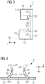
- FIG. 13 shows a second side view of the one in FIG FIGN 1 and 2 shown securing element 1 of the loss prevention system 2.
- the third tab 73 has a third recess 123.
- the third recess 123 is slit-shaped and has a third recess base 133.
- the third recess base 133 is designed to correspond to the first stop surface 181 and, in the embodiment, is designed to be planar by way of example.
- the third recess base 133 is arranged at a distance from the first stop surface 181.
- the third recess 123 is arranged on a side of the third tab 73 facing the fourth tab 74 and is open towards the fourth tab 74.
- the third recess 123 has a rectangular cross section and adjoins the third section 33.
- the first engagement section 171 of the first component 141 engages in the third recess 123 in sections.
- the third recess 123 can, however, also be omitted. In this case, the third tab 73 is only designed to rest on the first component 141, instead of receiving it at least in sections in the third recess 123.
- the fourth tab 74 has a fourth recess 124.
- the fourth recess 124 is slit-shaped and has a fourth recess base 134.
- the fourth recess base 134 is designed to correspond to the second stop surface 182 and, in the embodiment, is designed to be planar by way of example.
- the fourth recess base 134 is arranged at a distance from the second stop surface 182.
- the fourth recess 124 is arranged on a side of the fourth tab 74 facing the third tab 73 and is open towards the third tab 73. In the representation of the FIG 3 the fourth recess 124 has a rectangular cross section and is located on the third section 31.
- the second engagement section 172 of the second holder 152 of the second component 142 engages in the fourth recess 124.
- the third recess 123 is formed longer in the z-direction than the fourth recess 124, while, for example, the fourth recess 124 is formed wider along the x-axis than the third recess 123.
- the third recess 123 and the first recess formed the same depth, wherein the first recess base and the third recess base 133 are arranged in a common xy plane.
- the second recess and the fourth recess 124 are designed to have the same depth in the z-direction, the second recess base and the fourth recess base 134 being arranged in a common further xy plane.
- the recesses 123, 124 can also be designed differently.
- FIG. 13 shows a top view of the one in FIG FIGN 1 to 4 shown securing element 1 along the z-axis.
- the third tab 73 has a third tab area 83 and a third curved area 93.
- the third tab area 83 adjoins a third free end 113 of the third tab 73.
- the first and third arc areas 91, 93 are designed as quarter-circle arcs, for example.
- the third arched area 93 connects the third tab area 83 with the third section 33.
- the third arched area 93 can, however, also be omitted. In this case, the third tab area 83 is directly connected to the third section 33.
- the third tab area 83 is planar and extends in a fourth plane 24.
- the fourth plane 24 is aligned in a first direction 11 parallel to the third section 33 and inclined in a second direction 12, preferably perpendicular, to the first section 31.
- the first direction 11 is oriented parallel to the z-axis.
- the second direction 12 is oriented parallel to the x-axis when the fourth plane 24 is oriented perpendicular to the third section 33.
- the second level 22 and the third level overlap in the embodiment of the securing element 1, which is why the second tab area in FIG FIG 4 cannot be seen because it is covered by the first tab area 81.
- the second and the third plane 22 can, however, also be designed parallel and offset to one another or inclined to one another, so that the second plane 22 and the third plane intersect one another.
- the fourth level 24 and the fifth level overlap in the embodiment, which is why the fourth tab area in FIG FIG 4 cannot be seen because it is covered by the third tab area 83.
- the fourth and fifth planes 24 can, however, also be aligned parallel and offset or inclined to one another, so that the fourth plane 24 and the fifth plane intersect one another.
- the second component 142 falls down until the second stop surface 182 of the second engagement section 172 is on the second recess base 132 of the second recess 122 and on the fourth recess base 134 of the fourth Recess 124 rests.
- the first recess 121 and the third recess 123 can also be omitted.
- the second component 142 rests on the second tab 72 and the fourth tab 74.
- the first recess 121 and the third recess 123 can also be omitted.
- the first tab 71 and the third tab 73 rest on the first component 141.
- the securing element 1 is assembled by sliding the securing element 1 laterally onto the first engagement section 171 and, if present, onto the second engagement section 172, so that the first component 141 and the second component 142 between the first and third tabs 71, 73 and the second and fourth tabs 72, 74 are arranged at least in sections.
- the recesses 121, 122, 123, 124 can also be designed in such a way that the securing element can be applied to the engagement sections 171, 172 in a rotary-tilting movement (about the y-axis).
- the second component 142 is already temporarily fixed.
- a fitter can then attach the releasable connections 51, 52, 53 alone (without further assistance from another fitter) and fasten the second component 142 to the first component 141.
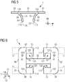
- FIG 5 Figure 13 shows a bottom view of that in the FIGN 1 to 3 shown securing element 1 along the z-axis.
- the fourth tab 74 has a fourth tab area 84 and a fourth curved area 94.
- the fourth tab area 84 adjoins a fourth free end 114 of the fourth tab 74.
- the second and fourth arcuate areas 92, 94 are designed, for example, as quadrant arcs.
- the fourth arched area 94 connects the fourth tab area 84 with the third section 33.
- the fourth arched area 94 can, however, also be omitted. In this case, the fourth is tab area 84 connected directly to the third section 33.
- the second tab area 82 is planar and extends in a third plane 23.
- the fourth tab area 84 is planar and extends in a fifth plane 25.
- the third and fifth planes 23, 25 are each in a first direction 11 parallel to aligned with the first section 31 and inclined in a second direction 12, preferably perpendicular, to the first section 31.
- the first direction 11 is oriented parallel to the z-axis.
- the second direction 12 is oriented parallel to the x-axis when the third and fifth planes 23, 25 are oriented perpendicular to the first section 31.
- the tab areas 82, 84 are aligned upright to the first and third sections 31, 33 as described above, ie that an extension of the tab area 82, 84 in the z-direction is higher as a thickness of the tab area 82, 84 in the y direction.
- FIG. 13 shows a front view of that in FIG FIGN 1 to 5 shown fuse element 1 along the x-axis.
- the recesses 121, 122, 123, 124 are of equal width in the y direction. Of course, a different configuration of the recesses 121, 122, 123, 124 is also conceivable.
- the embodiment shown is indicated by means of dashed lines.
- the first tab 71 and the second tab 72 do not have to be arranged together on the first long side 61 of the first section 31.
- the first flap 71 can also be arranged on the first long side 61 and the second flap 72 can be arranged on the second long side 62 of the first section 31.
- a reverse arrangement is also possible, so that the first tab 71 on the second long side 62 and the second tab 72 are arranged on the first long side 61 of the first section 31.
- the first tab 71 and the second tab 72 can also be arranged together on the second long side 62 (on a side facing away from the second section 32) of the first section 31.
- the third tab 73 and the fourth tab 74 do not have to be arranged together on the first long side 65 of the third section 33.
- the third flap 73 can also be arranged on the first long side 65 and the fourth flap 74 can be arranged on the second long side 66 of the third section 33.
- a reverse arrangement is also possible, so that the third tab 73 is arranged on the second long side 66 and the fourth tab 74 is arranged on the first long side 65 of the third section 33.
- the third tab 73 and the fourth tab 74 can also be arranged together on the second long side 66 (on a side facing away from the second section 32) of the third section 33.
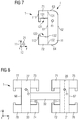
- FIG. 11 shows a front view of a second embodiment of a securing element 1. Unless otherwise mentioned, the securing element 1 is identical to that in FIG FIGN 1 to 6 described fuse element 1 formed.
- the securing element 1 only has the first section 31, while the second and third sections 32, 33 are dispensed with. Furthermore, the securing element 1 of the second embodiment has only the first and the second tab 71, 72. Although not absolutely necessary, the first tab 71 and the second tab 72 in the illustration of FIG FIG 7 the first and second recesses 121, 122, respectively.
- the first long side 61 between the first tab 71 and the second tab 72 is designed to be flat without interruption.
- This configuration is particularly compact and is suitable in particular for securing components 141, 142 in a cramped installation space situation.
- FIG 8 shows a front view of a securing element 1 according to a third embodiment.
- FIG 8 The ones in the FIG 8 The illustrated third embodiment of the fuse element 1 is, unless otherwise explained, identical to that in the FIGS. 1 to 6 Fuse element 1 shown is formed.
- the securing element 1 has, for example, a total of eight tabs 71-78.
- the securing element 1 has, for example, fifth to eighth tabs 75, 76, 77, 78.
- the number of tabs 71-78 can be freely selected, but should not be less than in FIG 7 explained.
- the first to fourth tabs 71, 72, 73, 74 are each designed and arranged according to the first embodiment of the security element 1.
- the seventh flap 77 is opposite the third flap 73 in the y-direction and is arranged mirror-symmetrically to the third flap 73 with respect to a second plane of symmetry 27, the second plane of symmetry 27 being centered between the first long side 65 and the second long side 66 of the third section 33 is trained.
- the eighth bracket 78 is arranged opposite the fourth bracket 74 in the y-direction and is designed with mirror symmetry to the fourth bracket 74 with respect to the second plane of symmetry 27. In the z direction, the seventh and eighth tabs 77, 78 are arranged opposite together on the second long side 65 of the third section 33.
- the fifth bracket 75 is opposite the first bracket 71 in the y-direction and is arranged mirror-symmetrically to the first bracket 71 with respect to a third plane of symmetry 28, with the third plane of symmetry 28 is formed centrally between the first long side 61 and the second long side 62 of the first section 31.
- the sixth bracket 76 is arranged opposite the second bracket 72 in the y-direction and is designed with mirror symmetry to the second bracket 72 with respect to the third plane of symmetry 28. In the z-direction, the fifth and sixth tabs 75, 76 are arranged opposite together on the second long side 62 of the first section 31.
- FIG 9 shows a first side view of the in FIG 8 shown fuse element 1.
- FIG 10 FIG. 13 shows a top view of the one in FIG FIGN 8 and 9 shown fuse element 1.
- the fifth and seventh tabs 75, 77 also have tab areas and curved areas, the tab areas extending along planes which preferably run parallel to the second, third, fourth and fifth planes 22, 24.
- the arched areas can also be omitted.
- the sixth and eighth tabs are also designed in this way, which is shown in FIG 10 cannot be seen because the fifth flap 75 covers the sixth flap and the seventh flap 77 covers the eighth flap.
Landscapes
- Engineering & Computer Science (AREA)
- General Engineering & Computer Science (AREA)
- Mechanical Engineering (AREA)
- Connection Of Plates (AREA)
- Fuses (AREA)
Description
- Die vorliegende Erfindung betrifft ein Verliersicherungssystem mit einem Sicherungselement zum Sichern von Bauteilen eines Schienenfahrzeugs.
- Im Eisenbahnbereich kann es die Vorgabe geben, dass Schraubverbindungen von im Unterflurbereich eines Schienenfahrzeugs montierten Bauteilen nicht auf Zug belastet sein dürfen oder, dass das Schienenfahrzeug mit einem Sicherungselement ausgestattet sein muss, wenn eine Schraubverbindung im Unterflurbereich auf Zug belastet ist. Eine solche Vorgabe ist beispielsweise in den USA zu beachten.
- Aus dem Stand der Technik
EP 1 050 940 A1 undUS 3,730,466 A1 sind Befestigungssysteme mit Klammern bekannt. - Aus dem Stand der Technik ist ein Sicherungselement mit horizontal angeordneten und beidseitig gesicherten Bolzen zwischen einer Wagenkastenstruktur und einem anzubauenden Bauteil bekannt.
- Eine Aufgabe der vorliegenden Erfindung besteht darin, ein verbessertes Sicherungselement zum Sichern von Bauteilen eines Fahrzeugs, insbesondere eines Schienenfahrzeugs und ein Verliersicherungssystem mit mindestens einem Sicherungselement und einem gesicherten Bauteil anzugeben.
- Diese Aufgaben werden durch ein Verliersicherungssystem mit den Merkmalen des unabhängigen Anspruchs 1 gelöst. In den abhängigen Ansprüchen sind verschiedene Ausführungsformen angegeben.
- Ein Sicherungselement zum Sichern von Bauteilen eines Fahrzeugs, insbesondere eines Schienenfahrzeugs weist einen ersten Abschnitt, eine erste Lasche und eine zweite Lasche auf.
- Der erste Abschnitt ist in Form einer länglichen Platte ausgebildet und erstreckt sich in einer ersten Ebene. In dem ersten Abschnitt ist mindestens eine erste Durchgangsöffnung angeordnet. Die erste Durchgangsöffnung ist dazu ausgebildet, eine erste lösbare Verbindung zum Befestigen des Sicherungselements an einem ersten Bauteil zumindest abschnittsweise aufzunehmen. Der erste Abschnitt weist eine lange Seite auf. Die erste Lasche und die zweite Lasche sind an der langen Seite des ersten Abschnitts gegenüberliegend zueinander angeordnet und ragen aus der ersten Ebene auf eine gemeinsame Seite des ersten Abschnitts. Die erste Lasche ist dazu ausgebildet, oberseitig an dem ersten Bauteil aufzuliegen. Die zweite Lasche ist dazu ausgebildet, ein zweites Bauteil unterseitig abzustützen und gegen ein Herabfallen zu sichern.
- Diese Ausgestaltung hat den Vorteil, dass eine einfache und zuverlässige Verliersicherung bereitgestellt werden kann, die insbesondere, wenn das zweite Bauteil an dem ersten Bauteil mittels einer auf Zug belasteten Schraubverbindung befestigt wird, bei einem Ausfall der Schraubverbindung ein Abfallen des zweiten Bauteils, das unterseitig des ersten Bauteils angeordnet ist, dadurch verhindert, dass die erste Lasche oberseitig auf dem ersten Bauteil aufliegt, während das zweite Bauteil oberseitig auf der zweiten Lasche aufliegt. Das Sicherungselement ist ferner besonders einfach und kostengünstig herstellbar sowie einfach durch nur eine Person montierbar.
- In einer Ausführungsform weist die erste Lasche eine erste Aussparung auf. Die erste Aussparung ist dazu ausgebildet, das erste Bauteil zumindest abschnittsweise aufzunehmen. Die erste Lasche ist mit einem ersten festen Ende mit der langen Seite des ersten Abschnitts verbunden. Die erste Aussparung ist auf einer zur zweiten Lasche zugewandten Seite der ersten Lasche angeordnet und ist zur zweiten Lasche hin geöffnet. Die erste Aussparung ist angrenzend an das feste Ende angeordnet und ist vorzugsweise schlitzförmig ausgebildet. Diese Ausgestaltung hat den Vorteil, dass in montiertem Zustand das erste Bauteil in die erste Aussparung eingreifen kann, wodurch ein Verrutschen des Sicherungselements in zumindest eine Raumrichtung verhindert werden kann. In eine zweite Raumrichtung kann das Sicherungselement entlang dem ersten Bauteil verschoben werden. Dadurch ist eine einfache Positionierung des zweiten Bauteils relativ zum ersten Bauteil und des Sicherungselements relativ zum ersten Bauteil möglich.
- In einer Ausführungsform weist die zweite Lasche eine zweite Aussparung auf. Die zweite Aussparung ist dazu ausgebildet, das zweite Bauteil zumindest abschnittsweise aufzunehmen. Die zweite Lasche ist mit einem zweiten festen Ende mit der langen Seite des ersten Abschnitts verbunden. Die zweite Aussparung ist angrenzend an das zweite feste Ende angeordnet. Die zweite Aussparung ist vorzugsweise schlitzförmig ausgebildet. Die zweite Aussparung ist auf einer zur ersten Lasche zugewandten Seite der zweiten Lasche angeordnet und ist zur ersten Lasche hin geöffnet. In montiertem Zustand des Verliersicherungssystems kann in die zweite Aussparung das zweite Bauteil zumindest abschnittsweise eingreifen, wodurch ein Verrutschen des zweiten Bauteils verhindert werden kann. Dadurch liegt das zweite Bauteil sicher an der zweiten Lasche an.
- In einer Ausführungsform weist die erste Lasche einen ersten Laschenbereich und einen ersten Bogenbereich auf. Die zweite Lasche weist einen zweiten Laschenbereich und einen zweiten Bogenbereich auf. Der erste und der zweite Laschenbereich sind plattenförmig ausgebildet. Der erste Laschenbereich erstreckt sich in einer zweiten Ebene. Der zweite Laschenbereich erstreckt sich in einer dritten Ebene. Die zweite und die dritte Ebene sind jeweils in einer ersten Richtung parallel zum ersten Abschnitt und in einer zweiten Richtung geneigt, vorzugweise senkrecht, zu dem ersten Abschnitt angeordnet. Der erste Laschenbereich grenzt an ein erstes freies Ende an. Der zweite Laschenbereich grenzt an ein zweites freies Ende an. Der erste Bogenbereich verbindet den ersten Laschenbereich mit dem ersten Abschnitt. Der zweite Bogenbereich verbindet den zweiten Laschenbereich mit dem ersten Abschnitt. Dadurch kann die erste Lasche mit ihrem ersten Laschenbereich, der sich in der zweite Ebene erstreckt, auf dem ersten Bauteil aufliegen. Das zweite Bauteil kann dadurch auf dem zweiten Laschenbereich der zweiten Lasche, der sich in der dritten Ebene erstreckt, aufliegen.
- In einer Ausführungsform überlappen sich die zweite Ebene und die dritte Ebene oder die zweite Ebene ist parallel zu der dritten Ebene ausgebildet. Dadurch kann das Werkzeug zur Herstellung des Sicherungselements besonders einfach ausgebildet sein.
- In einer Ausführungsform weist das Sicherungselement einen zweiten Abschnitt und einen dritten Abschnitt auf. Der zweite Abschnitt und der dritte Abschnitt sind jeweils in Form einer länglichen Platte ausgebildet. Der zweite Abschnitt und der dritte Abschnitt erstrecken sich in der ersten Ebene. Der dritte Abschnitt und der erste Abschnitt sind versetzt zueinander angeordnet. Der zweite Abschnitt ist geneigt, vorzugsweise senkrecht, zu dem ersten Abschnitt und/oder zu dem dritten Abschnitt angeordnet. Der zweite Abschnitt ist zwischen dem ersten Abschnitt und dem dritten Abschnitt angeordnet und verbindet den ersten Abschnitt mit dem dritten Abschnitt. Der dritte Abschnitt ist parallel zum ersten Abschnitt angeordnet Das Sicherungselement weist ferner eine dritte Lasche und eine vierte Lasche auf. Der dritte Abschnitt weist eine lange Seite auf. Die dritte Lasche und die vierte Lasche sind an der langen Seite des dritten Abschnitts gegenüberliegend angeordnet und ragen aus der ersten Ebene auf eine gemeinsame Seite des dritten Abschnitts und auf die gleiche Seite wie die erste und zweite Lasche. Die dritte Lasche ist dazu ausgebildet, oberseitig an dem ersten Bauteil aufzuliegen. Die vierte Lasche ist dazu ausgebildet, das zweite Bauteil unterseitig abzustützen und gegen ein Herabfallen zu sichern. Dadurch kann das Sicherungselement besonders hohe Abstützkräfte aufnehmen.
- In einer Ausführungsform weist der dritte Abschnitt mindestens eine zweite Durchgangsöffnung auf. Die zweite Durchgangsöffnung ist dazu ausgebildet, eine zweite lösbare Verbindung zum Befestigen des Sicherungselements an dem ersten Bauteil zumindest abschnittsweise aufzunehmen. Dadurch kann das Sicherungselement durch eine zweite lösbare Verbindung verdrehsicher mit dem ersten Bauteil verbunden sein.
- In einer Ausführungsform weist die dritte Lasche eine dritte Aussparung und/oder die vierte Lasche eine vierte Aussparung auf. Die dritte Lasche ist mit einem dritten festen Ende und die vierte Lasche ist mit einem vierten festen Ende mit der langen Seite des dritten Abschnitts verbunden. Die dritte Aussparung ist dazu ausgebildet, das erste Bauteil zumindest abschnittsweise aufzunehmen und/oder die vierte Aussparung ist dazu ausgebildet, das zweite Bauteil zumindest abschnittsweise aufzunehmen. Die dritte Aussparung ist angrenzend an das dritte feste Ende der dritten Lasche und/oder die vierte Aussparung an das vierte feste Ende der vierten Lasche angeordnet. Die dritte Aussparung ist auf einer zur vierten Lasche zugewandten Seite der dritten Lasche angeordnet und zur vierten Lasche hin geöffnet und/oder die vierte Aussparung ist auf einer zur dritten Lasche zugewandten Seite der vierten Lasche angeordnet und zur dritten Lasche hin geöffnet. Dadurch ist das zweite Bauteil gegen ein Herabfallen besonders zuverlässig gesichert.
- In einer Ausführungsform erstrecken sich die dritte Lasche abschnittsweise in einer vierten Ebene und die vierte Lasche abschnittsweise in einer fünften Ebene. Die zweite Ebene und die vierte Ebene und/oder die dritte Ebene und die fünfte Ebene sind parallel zueinander angeordnet.
- In einer Ausführungsform sind die dritte Lasche und/oder die vierte Lasche auf einer dem ersten Abschnitt zugewandten Seite des dritten Abschnitts und die erste Lasche und/oder die zweite Lasche auf einer dem dritten Abschnitt zugewandten Seite des ersten Abschnitts angeordnet.
- In einer Ausführungsform sind die dritte Lasche und/oder die vierte Lasche auf einer dem ersten Abschnitt abgewandten Seite des dritten Abschnitts und die erste Lasche und/oder die zweite Lasche auf einer dem dritten Abschnitt abgewandten Seite des ersten Abschnitts angeordnet.
- Ein Verliersicherungssystem, vorzugsweise ein Schienenfahrzeug, weist mindestens ein Sicherungselement, ein erstes Bauteil und ein zweites Bauteil und wenigstens eine erste lösbare Verbindung und eine dritte lösbare Verbindung auf. Die erste lösbare Verbindung greift durch die erste Durchgangsöffnung und befestigt das Sicherungselement an dem ersten Bauteil. Die dritte lösbare Verbindung verbindet auf Zug belastet das erste Bauteil mit dem zweiten Bauteil. Das erste Bauteil und das zweite Bauteil sind zwischen der ersten Lasche und der zweiten Lasche zumindest abschnittweise angeordnet. Das zweite Bauteil liegt bei Versagen und/oder Lösen der dritten lösbaren Verbindung auf der zweiten Lasche auf und die zweite Lasche sichert das zweite Bauteil vor dem Herunterfallen. Die erste Lasche liegt bei Versagen und/oder Lösen der ersten lösbaren Verbindung auf dem ersten Bauteil auf und hält das Sicherungselement an dem ersten Bauteil.
- In Ausführungsform weist das erste Bauteil einen ersten Eingriffsabschnitt auf. Der erste Eingriffsabschnitt ist parallel zu dem ersten Abschnitt ausgerichtet. Der erste Eingriffsabschnitt greift in die erste Aussparung ein. Bei Versagen und/oder Lösen der dritten lösbaren Verbindung liegt eine erste Anschlagsfläche des ersten Eingriffsabschnitts, die an einem freien Ende des ersten Eingriffsabschnitts angeordnet ist, auf einem Grund der ersten Aussparung auf. Dadurch liegt die erste Lasche sicher auf dem ersten Bauteil auf, wenn der erste Eingriffsabschnitt des ersten Bauteils in die erste Aussparung eingreift.
- In einer Ausführungsform weist das zweite Bauteil einen zweiten Eingriffsabschnitt aufweist. Der zweite Eingriffsabschnitt ist parallel zu dem ersten Abschnitt ausgerichtet und erstreckt sich in einer entgegengesetzten Richtung zu dem ersten Eingriffsabschnitt. Der zweite Eingriffsabschnitt greift in die zweite Aussparung ein. Bei Versagen und/oder Lösen der dritten lösbaren Verbindung liegt eine zweite Anschlagsfläche des zweiten Eingriffsabschnitts, die an einem freien Ende des zweiten Eingriffsabschnitts angeordnet ist, auf einem Grund der zweiten Aussparung auf. Dadurch wird ein Abrutschen des Sicherungselements von den Bauteilen in teilmontiertem Zustand zuverlässig vermieden.
- Die oben beschriebenen Eigenschaften, Merkmale und Vorteile dieser Erfindung sowie die Art und Weise, wie diese erreicht werden, werden klarer und deutlicher verständlich im Zusammenhang mit der folgenden Beschreibung der Ausführungsbeispiele, die im Zusammenhang mit den Zeichnungen näher erläutert werden, wobei
- FIG 1
- eine perspektivische Ansicht eines Verliersicherungssystems mit einem Sicherungselement gemäß einer ersten Ausführungsform;
- FIG 2
- eine erste Seitenansicht auf das in
FIG 1 gezeigte Verliersicherungssystem; - FIG 3
- eine zweite Seitenansicht auf das Sicherungselement des in den
FIGN 1 und2 gezeigten Verliersicherungssystems; - FIG 4
- eine Draufsicht auf das in den
FIGN 1 bis 3 gezeigte Sicherungselement; - FIG 5
- eine Unteransicht auf das in den
FIGN 1 bis 4 gezeigte Sicherungselement; - FIG 6
- eine Vorderansicht auf das in den
FIGN 1 bis 5 gezeigte Sicherungselement; - FIG 7
- eine Vorderansicht auf eine zweite Ausführungsform des Sicherungselements;
- FIG 8
- eine Vorderansicht auf eine dritte Ausführungsform des Sicherungselements;
- FIG 9
- eine erste Seitenansicht auf die dritte Ausführungsform des Sicherungselements;
- FIG 10
- eine Draufsicht auf die dritte Ausführungsform des Sicherungselements.
- In allen Figuren wird auf ein Koordinatensystem mit einer x-Achse, einer y-Achse und einer z-Achse bezuggenommen. Das Koordinatensystem ist als Rechtssystem ausgebildet.
-
FIG 1 zeigt eine dreidimensionale Ansicht eines Ausschnitts eines als Verliersicherungssystem 2 ausgebildeten Schienenfahrzeugs mit einem Sicherungselement 1, einem ersten Bauteil 141 und einem zweiten Bauteil 142. - Das erste Bauteil 141 kann beispielsweise ein Sandkasten sein. Sandkästen werden bei Schienenfahrzeugen typischerweise im Unterflurbereich montiert, wobei der Sand verwendet wird, um die Reibung bei einer Notbremsung des Schienenfahrzeugs zu erhöhen. Das zweite Bauteil 142 kann beispielsweise ein Sandkastendeckel sein. Das zweite Bauteil 142 ist unterseitig des ersten Bauteils 141 angeordnet. Selbstverständlich kann das erste Bauteil 141 und/oder das zweite Bauteil 142 eine andere unterflur angeordnete Komponente des Schienenfahrzeugs 2 sein.
- In
FIG 1 sind das erste Bauteil 141 und das zweite Bauteil 142 aus Übersichtlichkeitsgründen nur abschnittsweise dargestellt. Auch ist nur ein Sicherungselement 1 dargestellt. Es ist auch möglich, dass eine Mehrzahl von Sicherungselementen 1 zum Sichern des zweiten Bauteils 142 gegen ein Herabfallen verwendet wird. Die Anzahl der zum Sichern des zweiten Bauteils 142 notwendigen Sicherungselemente 1 kann beispielsweise von der Größe und der Masse des zu sichernden zweiten Bauteils 142 abhängen. - Das erste Bauteil 141 weist einen ersten Halteabschnitt 161 und einen ersten Eingriffsabschnitt 171 auf. Der erste Eingriffsabschnitt 171 ist mit dem ersten Halteabschnitt 161 verbunden. Der erste Eingriffsabschnitt 171 und der erste Halteabschnitt 161 sind plattenförmig ausgebildet.
- Das zweite Bauteil 142 weist einen zweiten Halteabschnitt 162 und einen mit dem zweiten Halteabschnitt 162 verbundenen zweiten Eingriffsabschnitt 172 auf. Der zweite Eingriffsabschnitt 172 und der zweite Halteabschnitt 162 sind plattenförmig ausgebildet. Die Halteabschnitte 161, 162 sind schräg, bevorzugt senkrecht, zu den Eingriffsabschnitten 171, 172 ausgebildet.
- Der erste Eingriffsabschnitt 171 und der zweite Eingriffsabschnitt 172 sind beispielhaft jeweils parallel zur z-Achse ausgerichtet. Der zweite Eingriffsabschnitt 172 erstreckt sich in einer entgegengesetzten Richtung zum ersten Eingriffsabschnitt 171. Der zweite Eingriffsabschnitt 172 des zweiten Bauteils 142 kann aber auch entfallen. In diesem Fall weist das zweite Bauteil 142 lediglich den zweiten Halteabschnitt 162 auf.
- Der erste und der zweite Eingriffsabschnitt 171, 172 weisen jeweils eine erste und eine zweite Anschlagsfläche 181, 182 auf. Die Anschlagsflächen 181, 182 sind jeweils an einem freien Ende der Eingriffsabschnitte 171, 172 angeordnet und sind parallel zu den Halteabschnitten 161, 162 ausgerichtet.
- Das Sicherungselement 1 weist einen ersten Abschnitt 31, einen zweiten Abschnitt 32 und einen dritten Abschnitt 33 auf. Der erste Abschnitt 31 ist in Form einer länglichen Platte ausgebildet und erstreckt sich in einer ersten Ebene 21. Eine erste lange Seite 61 und eine zweite lange Seite 62 des ersten Abschnitts 31 verlaufen beispielhaft parallel zur z-Achse. Eine erste kurze Seite 63 und eine zweiten kurze Seite 64 sind in y-Richtung gegenüberliegend angeordnet und verbinden die beiden langen Seiten 61, 62 des ersten Abschnitts 31 miteinander.
- In dem ersten Abschnitt 31 ist eine erste Durchgangsöffnung 41 angeordnet. Die erste Durchgangsöffnung 41 kann als Bohrung ausgebildet sein. Der erste Abschnitt 31 kann auch eine Mehrzahl erster Durchgangsöffnungen 41 aufweisen.
- Der zweite Abschnitt 32 und der dritte Abschnitt 33 sind jeweils in Form einer länglichen Platte ausgebildet. Der zweite Abschnitt 32 und der dritte Abschnitt 33 erstrecken sich in der ersten Ebene 21. Der dritte Abschnitt 33 und der erste Abschnitt 31 sind in y-Richtung versetzt zueinander angeordnet. Im dargestellten Beispiel der
FIG 1 sind der erste Abschnitt 31 und der dritte Abschnitt 33 beispielhaft parallel zueinander ausgerichtet. Der zweite Abschnitt 32 ist geneigt, vorzugsweise senkrecht, zu dem ersten Abschnitt 31 und/oder zu dem dritten Abschnitt 33 angeordnet. Der zweite Abschnitt 32 ist zwischen dem ersten Abschnitt 31 und dem dritten Abschnitt 33 angeordnet und verbindet den ersten Abschnitt 31 mit dem dritten Abschnitt 33. In z-Richtung ist der zweite Abschnitt 32 schlanker ausgebildet als der erste Abschnitt 31 und der dritte Abschnitt 33. - Der dritte Abschnitt 33 weist mindestens eine zweite Durchgangsöffnung 42 auf. Die zweite Durchgangsöffnung 42 ist als Bohrung ausgebildet und erstreckt sich in x-Richtung durch den dritten Abschnitt 33. Die erste Durchgangsöffnung 41 und die zweite Durchgangsöffnung 42 sind beispielhaft identisch ausgebildet und sind in z-Richtung auf gleicher Höhe angeordnet sowie verlaufen parallel. Der dritte Abschnitt 33 kann auch eine Mehrzahl zweiter Durchgangsöffnungen 42 aufweisen.
- Ferner sind im ersten Eingriffsabschnitt 171 eine dritte Durchgangsöffnung und eine vierte Durchgangsöffnung angeordnet. In
FIG 1 sind die dritte und die vierte Durchgangsöffnung durch das Sicherungselement 1 verdeckt. Die dritte Durchgangsöffnung fluchtet mit der ersten Durchgangsöffnung 41 und die zweite Durchgangsöffnung 42 fluchtet mit vierten Durchgangsöffnung. - Das Verliersicherungssystem 2 weist ferner eine erste lösbare Verbindung 51 und vorzugsweise eine zweite lösbare Verbindung 52 auf. Die erste und/oder zweite lösbare Verbindung 51, 52 ist als Schraubverbindung ausgebildet. Eine erste Schraube 54 der ersten lösbaren Verbindung 51 durchgreift die erste Durchgangsöffnung 41 und dritte Durchgangsöffnung. Eine zweite Schraube 55 durchgreift die zweite Durchgangsöffnung 42 und die vierte Durchgangsöffnung. Die lösbare Verbindung 51, 52 befestigt das Sicherungselement 1 am ersten Eingriffsabschnitt 171 lösbar. Auch ist eine andere Ausgestaltung der lösbaren Verbindung 51, 52 denkbar.
- Das Sicherungselement 1 weist ferner eine erste Lasche 71, eine zweite Lasche 72, eine dritte Lasche 73 und eine vierte Lasche 74 auf. Dabei sind die erste Lasche 71 mit einem ersten festen Ende 101 und die zweite Lasche 72 mit einem zweiten festen Ende 102 in z-Richtung gegenüberliegend mit der ersten langen Seite 61 des ersten Abschnitts 31 verbunden. Die zweite lange Seite 62 des ersten Abschnitts 31 ist frei. Die erste Lasche 71 ist beispielhaft angrenzend an die erste kurze Seite 63 des ersten Abschnitts 31 angeordnet. Die zweite Lasche 72 ist angrenzend an die zweite kurze Seite 64 des ersten Abschnitts 31 angeordnet. Der zweite Abschnitt 32 ist beispielweise in mittiger Lage zwischen der ersten Lasche 71 und der zweiten Lasche 72 beabstandet zu der ersten und zweiten Lasche 71, 72 angeordnet.
- Der dritte Abschnitt 33 ist beispielhaft spiegelsymmetrisch bezogen auf eine erste Symmetrieebene 26 zum ersten Abschnitt 31 ausgebildet. Eine erste lange Seite 65 und eine zweite lange Seite 66 des dritten Abschnitts 33 verlaufen beispielhaft parallel zur z-Achse. Eine erste kurze Seite 67 und eine zweiten kurze Seite 68 des dritten Abschnitts 33 sind in z-Richtung gegenüberliegend angeordnet und verbinden die beiden langen Seiten 65, 66 des dritten Abschnitts 33 miteinander. Die erste kurze Seite 67 des dritten Abschnitts 33 ist beispielhaft auf gleicher Höhe in z-Richtung angeordnet wie die erste kurze Seite 63 des ersten Abschnitts 31. Die zweite kurze Seite 68 des dritten Abschnitts 33 ist beispielhaft auf gleicher Höhe in z-Richtung angeordnet wie die zweite kurze Seite 64 des ersten Abschnitts 31. Die erste lange Seite 61 des ersten Abschnitts 31 und die erste lange Seite 65 des dritten Abschnitts 65 sind auf einander zugewandten Seiten des ersten Abschnitts 31 und dritten Abschnitts 33 angeordnet. Die zweite lange Seite 62 des ersten Abschnitts 31 und die zweite lange Seite 65 des dritten Abschnitts 65 sind auf einander abgewandten Seiten des ersten und dritten Abschnitts 31, 33 angeordnet.
- Die dritte Lasche 73 ist mit einem dritten festen Ende 103 und die vierte Lasche 74 mit einem vierten festen Ende 104 in z-Richtung gegenüberliegend mit der ersten langen Seite 65 des dritten Abschnitts 33 verbunden. Die zweite lange Seite 66 des dritten Abschnitts 33 ist frei. Die dritte Lasche 73 ist angrenzend an die erste kurze Seite 67 des dritten Abschnitts 33 angeordnet. Die vierte Lasche 74 ist angrenzend an die zweite kurze Seite 68 des dritten Abschnitts 33 angeordnet.
- Alle Laschen 71, 72, 73, 74 ragen aus der ersten Ebene 21 auf eine gemeinsame und Bauteilen 141, 142zugewandte Seite des ersten und des dritten Abschnitts 31, 33.
- Das Sicherungselement 1 weist ein Metall, beispielsweise Eisen oder Stahl, auf. Das Sicherungselement 1 kann beispielsweise aus einem Blech mittels eines Stanz-Biegeverfahrens geformt werden. Das Sicherungselement 1 kann aber auch durch Verschweißen einzelner Komponenten und/oder mittels eines spanenden Verfahrens hergestellt werden.
-
FIG 2 zeigt eine erste Seitenansicht auf das inFIG 1 gezeigte Verliersicherungssystem. Dabei sind in der Seitenansicht lediglich die erste und die zweite Lasche 71, 72 zu erkennen, da diese die dritte und die vierte Lasche 73, 74 verdecken. - Die erste Lasche 71 weist eine erste Aussparung 121 auf. Die erste Aussparung 121 ist schlitzförmig ausgebildet und weist einen ersten Aussparungsgrund 131 auf. Der erste Aussparungsgrund 131 ist korrespondierend zur ersten Anschlagsfläche 181 ausgebildet und in der Ausführungsform beispielhaft plan ausgebildet. Der erste Aussparungsgrund 131 ist beabstandet zu der ersten Anschlagsfläche 181 angeordnet. Die erste Aussparung 121 ist auf einer zur zweiten Lasche 72 zugewandten Seite der ersten Lasche 71 angeordnet und zur zweiten Lasche 72 hin geöffnet. In der Darstellung der
FIG 2 weist die erste Aussparung 121 einen rechteckigen Querschnitt auf und grenzt an den ersten Abschnitt 31 an. In die erste Aussparung 121 greift der erste Eingriffsabschnitt 171 des ersten Bauteils 141 abschnittsweise ein. Die erste Aussparung 121 kann aber auch entfallen. - Die zweite Lasche 72 weist eine zweite Aussparung 122 auf. Die zweite Aussparung 122 ist schlitzförmig ausgebildet und weist einen zweiten Aussparungsgrund 132 auf. Der zweite Aussparungsgrund 132 ist korrespondierend zur zweiten Anschlagsfläche 182 ausgebildet und in der Ausführungsform beispielhaft plan ausgebildet. Der zweite Aussparungsgrund 132 ist beabstandet zu der zweiten Anschlagsfläche 182 angeordnet. Die zweite Aussparung 122 ist auf einer zur ersten Lasche 71 zugewandten Seite der zweiten Lasche 72 angeordnet und zur ersten Lasche 71 hin geöffnet. In der Darstellung der
FIG 2 weist die zweite Aussparung 122 einen rechteckigen Querschnitt auf und grenzt an den ersten Abschnitt 31 an. In die zweite Aussparung 122 greift der zweite Eingriffsabschnitt 172 der zweiten Halterung 152 des zweiten Bauteils 142 ein. - In
FIG 2 ist die erste Aussparung 121 in z-Richtung beispielhaft länger ausgebildet als die zweite Aussparung 122, während beispielhaft die zweite Aussparung 122 entlang der x-Achse breiter ausgebildet ist als die erste Aussparung 121. Auch können die Aussparungen 121, 122 andersartig ausgebildet sein. - Die erste Lasche 71 weist einen ersten Laschenbereich 81 und einen ersten Bogenbereich 91 auf. Die zweite Lasche 72 weist einen zweiten Laschenbereich 82 und eine zweiten Bogenbereich 92 auf. Der erste Laschenbereich 81 grenzt an ein erstes freies Ende 111 der ersten Lasche 71 an und der zweite Laschenbereich 82 grenzt an ein zweites freies Ende 112 der zweiten Lasche 72 an. Der Bogenbereich 92, 94 ist beispielhaft als Viertelkreisbogen ausgebildet. Der erste Bogenbereich 91 verbindet den ersten Laschenbereich 81 mit dem ersten Abschnitt 31. Der zweite Bogenbereich 92 verbindet den zweiten Laschenbereich 82 mit dem ersten Abschnitt 31. Der erste Bogenbereich 91 und der zweite Bogenbereich 94 können aber auch entfallen. In diesem Fall sind der erste Laschenbereich 81 und der zweite Laschenbereich 82 unmittelbar mit dem ersten Abschnitt 31 verbunden.
- Der erste Laschenbereich 81 ist plan ausgebildet und erstreckt sich in einer zweiten Ebene 22. Der zweite Laschenbereich 82 ist plan ausgebildet und erstreckt sich in einer dritten Ebene 23. Die zweite und die dritte Ebene 22, 23 sind jeweils in einer ersten Richtung 11 parallel zum ersten Abschnitt 31 ausgerichtet und in einer zweiten Richtung 12 geneigt, vorzugweise senkrecht, zu dem ersten Abschnitt 31 angeordnet. Die erste Richtung 11 ist parallel zur z-Achse orientiert. Die zweite Richtung 12 ist parallel zur x-Achse orientiert, wenn die zweite und die dritte Ebene 22, 23 senkrecht zum ersten Abschnitt 31 orientiert sind, was in
FIG 2 der Fall ist. Wichtig ist jedoch, um eine hohe Festigkeit des Sicherungselements 1 sicherzustellen, dass die Laschenbereiche 81, 82 wie oben beschrieben zu dem ersten Abschnitt 31 stehend ausgerichtet sind, d.h. dass eine Erstreckung des Laschenbereichs 81, 82 in z-Richtung höher ist als eine Dicke des Laschenbereichs 81, 82 in y-Richtung. - Der erste und der zweite Halteabschnitt 161, 162 sind aneinander gedrückt und mittels einer dritten lösbaren Verbindung 53 miteinander verbunden. Die dritte lösbare Verbindung 53 kann beispielsweise eine auf Zug belastete Schraubverbindung mit einer dritten Schraube 56 sein.
-
FIG 3 zeigt eine zweite Seitenansicht auf das in denFIGN 1 und2 gezeigte Sicherungselement 1 des Verliersicherungssystems 2. - Die dritte Lasche 73 weist eine dritte Aussparung 123 auf. Die dritte Aussparung 123 ist schlitzförmig ausgebildet und weist einen dritten Aussparungsgrund 133 auf. Der dritte Aussparungsgrund 133 ist korrespondierend zur ersten Anschlagsfläche 181 ausgebildet und in der Ausführungsform beispielhaft plan ausgebildet. Der dritte Aussparungsgrund 133 ist beabstandet zu der ersten Anschlagsfläche 181 angeordnet. Die dritte Aussparung 123 ist auf einer zur vierten Lasche 74 zugewandten Seite der dritten Lasche 73 angeordnet und zur vierten Lasche 74 hin geöffnet. In der Darstellung der
FIG 3 weist die dritte Aussparung 123 einen rechteckigen Querschnitt auf und grenzt an den dritten Abschnitt 33 an. In die dritte Aussparung 123 greift der erste Eingriffsabschnitt 171 des ersten Bauteils 141 abschnittsweise ein. Die dritte Aussparung 123 kann aber auch entfallen. In diesem Fall ist die dritte Lasche 73 lediglich dazu ausgebildet, auf dem ersten Bauteil 141 aufzuliegen, statt es zumindest abschnittsweise in der dritten Aussparung 123 aufzunehmen. - Die vierte Lasche 74 weist eine vierte Aussparung 124 auf. Die vierte Aussparung 124 ist schlitzförmig ausgebildet und weist einen vierten Aussparungsgrund 134 auf. Der vierte Aussparungsgrund 134 ist korrespondierend zur zweiten Anschlagsfläche 182 ausgebildet und in der Ausführungsform beispielhaft plan ausgebildet. Der vierte Aussparungsgrund 134 ist beabstandet zu der zweiten Anschlagsfläche 182 angeordnet. Die vierte Aussparung 124 ist auf einer zur dritten Lasche 73 zugewandten Seite der vierten Lasche 74 angeordnet und zur dritten Lasche 73 hin geöffnet. In der Darstellung der
FIG 3 weist die vierte Aussparung 124 einen rechteckigen Querschnitt auf und befindet sich am dritten Abschnitt 31. In die vierte Aussparung 124 greift der zweite Eingriffsabschnitt 172 der zweiten Halterung 152 des zweiten Bauteils 142 ein. - In
FIG 3 ist die dritte Aussparung 123 in z-Richtung beispielhaft länger ausgebildet als die vierte Aussparung 124, während beispielhaft die vierte Aussparung 124 entlang der x-Achse breiter ausgebildet ist als die dritte Aussparung 123. Ferner sind in z-Richtung die dritte Aussparung 123 und die erste Aussparung gleich tief ausgebildet, wobei der erste Aussparungsgrund und der dritte Aussparungsgrund 133 in einer gemeinsamen xy-Ebene angeordnet sind. Ferner sind in z-Richtung die zweite Aussparung und die vierte Aussparung 124 gleich tief ausgebildet, wobei der zweite Aussparungsgrund und der vierte Aussparungsgrund 134 in einer gemeinsamen weiteren xy-Ebene angeordnet sind. Auch können die Aussparungen 123, 124 andersartig ausgebildet sein. -
FIG 4 zeigt eine Draufsicht auf das in denFIGN 1 bis 4 gezeigte Sicherungselement 1 entlang der z-Achse. - Die dritte Lasche 73 weist einen dritten Laschenbereich 83 und eine dritten Bogenbereich 93 auf. Der dritte Laschenbereich 83 grenzt an ein drittes freies Ende 113 der dritten Lasche 73 an. Der erste und der dritte Bogenbereich 91, 93 sind beispielhaft als Viertelkreisbögen ausgebildet. Der dritte Bogenbereich 93 verbindet den dritten Laschenbereich 83 mit dem dritten Abschnitt 33. Der dritte Bogenbereich 93 kann aber auch entfallen. In diesem Fall ist der dritte Laschenbereich 83 unmittelbar mit dem dritten Abschnitt 33 verbunden.
- Der dritte Laschenbereich 83 ist plan ausgebildet und erstreckt sich in einer vierten Ebene 24. Die vierte Ebene 24 ist in einer ersten Richtung 11 parallel zum dritten Abschnitt 33 ausgerichtet und in einer zweiten Richtung 12 geneigt, vorzugweise senkrecht, zu dem ersten Abschnitt 31 angeordnet. Die erste Richtung 11 ist parallel zur z-Achse orientiert. Die zweite Richtung 12 ist parallel zur x-Achse orientiert, wenn die vierte Ebene 24 senkrecht zum dritten Abschnitt 33 orientiert ist. Wichtig ist jedoch, um eine hohe Festigkeit des Sicherungselements 1 sicherzustellen, dass der Laschenbereich83 wie oben beschrieben zu dem dritten Abschnitt 33 stehend ausgerichtet ist, d.h. dass eine Erstreckung des Laschenbereichs 83 in z-Richtung höher ist als eine Dicke des Laschenbereichs 83 in y-Richtung.
- Die zweite Ebene 22 und die dritte Ebene überlappen sich in der Ausführungsform des Sicherungselements 1, weshalb der zweite Laschenbereich in
FIG 4 nicht zu sehen ist, da er vom ersten Laschenbereich 81 verdeckt wird. Die zweite und die dritte Ebene 22 können aber auch parallel und versetzt zueinander oder geneigt zueinander ausgebildet sein, sodass die zweite Ebene 22 und die dritte Ebene einander schneiden. - Die vierte Ebene 24 und die fünfte Ebene überlappen sich in der Ausführungsform, weshalb der vierte Laschenbereich in
FIG 4 nicht zu sehen ist, da er vom dritten Laschenbereich 83 verdeckt wird. Die vierte und die fünfte Ebene 24 können aber auch parallel und versetzt oder geneigt zueinander ausgerichtet sein, sodass die vierte Ebene 24 und die fünfte Ebene einander schneiden. - Bei Versagen und/oder Lösen(beabsichtigt oder unbeabsichtigt) der dritten lösbaren Verbindung 53 fällt das zweite Bauteil 142 soweit herunter, bis die zweite Anschlagsfläche 182 des zweiten Eingriffsabschnitts 172 auf dem zweiten Aussparungsgrund 132 der zweiten Aussparung 122 und auf dem vierten Aussparungsgrund 134 der vierten Aussparung 124 aufliegt.
- In einer Weiterbildung der in
FIGN 1 bis 6 gezeigten Ausführungsform können die erste Aussparung 121 und die dritte Aussparung 123 aber auch entfallen. In diesem Fall liegt das zweite Bauteil 142 auf der zweiten Lasche 72 und der vierten Lasche 74 auf. - Bei einer gewichtsoptimierten Auslegung des Verliersicherungssystems 2 werden bei Versagen der dritten lösbaren Verbindung 53 die Schrauben 54, 55 der ersten und zweiten lösbaren Verbindung 51, 52 abgeschert, so dass die erste Anschlagsfläche 181 des ersten Eingriffsabschnitts 171 auf dem ersten Aussparungsgrund 131 und dem dritten Aussparungsgrund 133 aufliegt.
- In einer Weiterbildung der in den
FIGN 1 bis 6 gezeigten Ausführungsform können die erste Aussparung 121 und die dritte Aussparung 123 aber auch entfallen. In diesem Fall liegen die erste Lasche 71 und die dritte Lasche 73 auf dem ersten Bauteil 141 auf. - Die Montage des Sicherungselements 1 erfolgt, indem das Sicherungselement 1 seitlich auf den ersten Eingriffsabschnitt 171 und, falls vorhanden, auf den zweiten Eingriffsabschnitt 172 geschoben wird, sodass das erste Bauteil 141 und das zweite Bauteil 142 zwischen der ersten und der dritten Lasche 71, 73 und der zweiten und der vierten Lasche 72, 74 zumindest abschnittweise angeordnet sind. Auch können die Aussparungen 121, 122, 123 ,124 so ausgebildet sein, dass das Sicherungselement in einer Dreh-Kippbewegung (um die y-Achse) auf die Eingriffsabschnitte 171, 172 aufgebracht werden kann. Dadurch ist das zweite Bauteil 142 bereits provisorisch fixiert. Ein Monteur kann anschließend alleine (ohne weitere Hilfe durch einen weiteren Monteur) die lösbaren Verbindungen 51, 52, 53 anbringen und das zweite Bauteil 142 am ersten Bauteil 141 befestigen.
-
FIG 5 zeigt eine Unteransicht auf das in denFIGN 1 bis 3 gezeigte Sicherungselement 1 entlang der z-Achse. - Die vierte Lasche 74 weist einen vierten Laschenbereich 84 und eine vierten Bogenbereich 94 auf. Der vierte Laschenbereich 84 grenzt an ein viertes freies Ende 114 der vierten Lasche 74 an. Der zweite und der vierte Bogenbereich 92, 94 sind beispielhaft als Viertelkreisbögen ausgebildet. Der vierte Bogenbereich 94 verbindet den vierten Laschenbereich 84 mit dem dritten Abschnitt 33. Der vierte Bogenbereich 94 kann aber auch entfallen. In diesem Fall ist der vierte Laschenbereich 84 unmittelbar mit dem dritten Abschnitt 33 verbunden.
- Der zweite Laschenbereich 82 ist plan ausgebildet und erstreckt sich in einer dritten Ebene 23. Der vierte Laschenbereich 84 ist plan ausgebildet und erstreckt sich in einer fünften Ebene 25. Die dritte und die fünfte Ebene 23, 25 sind jeweils in einer ersten Richtung 11 parallel zum ersten Abschnitt 31 ausgerichtet und in einer zweiten Richtung 12 geneigt, vorzugweise senkrecht, zu dem ersten Abschnitt 31 angeordnet. Die erste Richtung 11 ist parallel zur z-Achse orientiert. Die zweite Richtung 12 ist parallel zur x-Achse orientiert, wenn die dritte und die fünfte Ebene 23, 25 senkrecht zum ersten Abschnitt 31 orientiert sind. Wichtig ist jedoch, um eine hohe Festigkeit des Sicherungselements 1 sicherzustellen, dass die Laschenbereiche 82, 84 wie oben beschrieben zu dem ersten und dritten Abschnitt 31, 33 stehend ausgerichtet sind, d.h. dass eine Erstreckung des Laschenbereichs 82, 84 in z-Richtung höher ist als eine Dicke des Laschenbereichs 82, 84 in y-Richtung.
-
FIG 6 zeigt eine Vorderansicht auf das in denFIGN 1 bis 5 gezeigte Sicherungselement 1 entlang der x-Achse. - In y-Richtung sind die Aussparungen 121, 122, 123, 124 gleich breit ausgebildet. Selbstverständlich ist auch eine unterschiedliche Ausgestaltung der Aussparungen 121, 122, 123, 124 denkbar.
- Eine Weiterbildung der in den
FIGN 1 bis 5 gezeigten Ausführungsform ist mittels gestrichelt gezeichneter Linien angedeutet. Die erste Lasche 71 und die zweite Lasche 72 müssen nicht gemeinsam an der ersten langen Seite 61 des ersten Abschnitts 31 angeordnet sein. Die erste Lasche 71 kann auch an der ersten langen Seite 61 und die zweite Lasche 72 kann an der zweiten langen Seite 62 des ersten Abschnitts 31 angeordnet sein. Auch eine umgekehrte Anordnung ist möglich, sodass die erste Lasche 71 an der zweiten langen Seite 62 und die zweite Lasche 72 an der ersten langen Seite 61 des ersten Abschnitts 31 angeordnet sind. Auch können die erste Lasche 71 und die zweite Lasche 72 gemeinsam an der zweiten langen Seite 62 (auf einer zum zweiten Abschnitt 32 abgewandten Seite) des ersten Abschnitts 31 angeordnet sein. - Die dritte Lasche 73 und die vierte Lasche 74 müssen nicht gemeinsam an der ersten langen Seite 65 des dritten Abschnitts 33 angeordnet sein. Die dritte Lasche 73 kann auch an der ersten langen Seite 65 und die vierte Lasche 74 kann an der zweiten langen Seite 66 des dritten Abschnitts 33 angeordnet sein. Auch eine umgekehrte Anordnung ist möglich, sodass die dritte Lasche 73 an der zweiten langen Seite 66 und die vierte Lasche 74 an der ersten langen Seite 65 des dritten Abschnitts 33 angeordnet sind. Auch können die dritte Lasche 73 und die vierte Lasche 74 gemeinsam an der zweiten langen Seite 66 (auf einer zum zweiten Abschnitt 32 abgewandten Seite) des dritten Abschnitts 33 angeordnet sein.
-
FIG 7 zeigt eine Vorderansicht auf eine zweite Ausführungsform eines Sicherungselements 1. Sofern nicht weiter erwähnt ist das Sicherungselement 1 identisch zu dem in denFIGN 1 bis 6 beschriebenen Sicherungselement 1 ausgebildet. - In dieser Ausführungsform weist das Sicherungselement 1 lediglich den ersten Abschnitt 31 auf, während auf den zweiten und dritten Abschnitt 32, 33 verzichtet wird. Ferner weist das Sicherungselement 1 der zweiten Ausführungsform nur die erste und die zweite Lasche 71, 72 auf. Obwohl nicht zwingend erforderlich, weisen die erste Lasche 71 und die zweite Lasche 72 in der Darstellung der
FIG 7 jeweils die erste und die zweite Aussparung 121, 122 auf. - Durch den Verzicht auf den zweiten und dritten Abschnitt 32, 33 ist die erste lange Seite 61 zwischen ersten Lasche 71 und der zweiten Lasche 72 unterbrechungsfrei plan ausgebildet. Diese Ausgestaltung ist besonders kompakt und eignet sich insbesondere zur Sicherung von Bauteilen 141, 142 bei einer beengten Bauraumsituation.
-
FIG 8 zeigt eine Vorderansicht auf ein Sicherungselement 1 gemäß einer dritten Ausführungsform. - Die in den
FIG 8 dargestellte dritte Ausführungsform des Sicherungselements 1 ist, sofern nicht anders erläutert, identisch zu dem in denFIG 1 bis 6 gezeigten Sicherungselement 1 ausgebildet. - Das Sicherungselement 1 weist beispielhaft insgesamt acht Laschen 71 - 78 auf. Neben der ersten bis vierten Lasche 71, 72, 73, 74 weist das Sicherungselement 1 beispielhaft eine fünfte bis achte Lasche 75, 76, 77, 78 auf. Die Anzahl der Laschen 71 -78 ist frei wählbar, sollte jedoch nicht geringer sein als in
FIG 7 erläutert. - Die erste bis vierte Lasche 71, 72, 73, 74 sind jeweils gemäß der ersten Ausführungsform des Sicherheitselements 1 ausgebildet und angeordnet.
- Die siebte Lasche 77 ist in y-Richtung der dritten Lasche 73 gegenüberliegend und zur dritten Lasche 73 spiegelsymmetrisch bezogen auf eine zweite Symmetrieebenen 27 angeordnet, wobei die zweite Symmetrieebene 27 mittig zwischen der ersten langen Seite 65 und der zweiten langen Seite 66 des dritten Abschnitts 33 ausgebildet ist. Die achte Lasche 78 ist in y-Richtung der vierten Lasche 74 gegenüberliegend angeordnet und zur vierten Lasche 74 spiegelsymmetrisch bezogen auf die zweite Symmetrieebene 27 ausgebildet. In z-Richtung sind die siebte und achte Lasche 77, 78 gegenüberliegend gemeinsam an der zweiten langen Seite 65 des dritten Abschnitts 33 angeordnet.
- Die fünfte Lasche 75 ist in y-Richtung der ersten Lasche 71 gegenüberliegend und zur ersten Lasche 71 spiegelsymmetrisch bezogen auf eine dritte Symmetrieebenen 28 angeordnet, wobei die dritte Symmetrieebene 28 mittig zwischen der ersten langen Seite 61 und der zweiten langen Seite 62 des ersten Abschnitts 31 ausgebildet ist. Die sechste Lasche 76 ist in y-Richtung der zweiten Lasche 72 gegenüberliegend angeordnet und zur zweiten Lasche 72 spiegelsymmetrisch bezogen auf die dritte Symmetrieebene 28 ausgebildet. In z-Richtung sind die fünfte und sechste Lasche 75, 76 gegenüberliegend gemeinsam an der zweiten langen Seite 62 des ersten Abschnitts 31 angeordnet.
-
FIG 9 zeigt eine erste Seitenansicht auf das inFIG 8 gezeigte Sicherungselement 1. - Alle Laschen weisen in x-Richtung und in y-Richtung die gleiche Ausdehnung auf. Aus diesem Grund sind in der Darstellung der
FIG 9 lediglich die siebte und die achte Lasche 77, 78 zu sehen, da sie alle anderen Laschen verdecken. Die siebte und die achte Lasche 77, 78 weisen in der beispielhaften Darstellung derFIG 9 jeweils eine Aussparung auf. Dies gilt auch für alle inFIG 9 verdeckten Laschen, wobei alle Aussparungen auch entfallen können. -
FIG 10 zeigt eine Draufsicht auf das in denFIGN 8 und9 gezeigte Sicherungselement 1. - Die fünfte und siebte Lasche 75, 77 weisen ebenfalls Laschenbereiche und Bogenbereiche auf, wobei die Laschenbereiche sich entlang von Ebenen erstrecken, die vorzugsweise parallel zu der zweiten, dritten, vierten und fünften Ebene 22, 24 verlaufen. Die Bogenbereiche können auch entfallen. Auch die sechste und die achte Lasche sind derart ausgebildet, was in
FIG 10 nicht zu sehen ist, da die fünfte Lasche 75 die sechste Lasche bedeckt und die siebte Lasche 77 die achte Lasche bedeckt.
Claims (13)
- Verliersicherungssystem (2),- bei dem das Verliersicherungssystem (2) mindestens ein Sicherungselement (1), ein erstes Bauteil (141), ein zweites Bauteil (142) und wenigstens eine erste lösbare Verbindung (51) und eine dritte lösbare Verbindung (53) aufweist,- bei dem das Sicherungselement (1) zum Sichern der beiden Bauteile (141, 142) des Schienenfahrzeugs (2) ausgebildet ist, wobei das Sicherungselement (1) einen ersten Abschnitt (31), eine erste Lasche (71) und eine zweite Lasche (72) aufweist, wobei der erste Abschnitt (31) in Form einer länglichen Platte ausgebildet ist und sich in einer ersten Ebene (21) erstreckt, wobei im ersten Abschnitt (31) mindestens eine erste Durchgangsöffnung (41) angeordnet ist, wobei die erste Durchgangsöffnung (41) ausgebildet ist, die erste lösbare Verbindung (51) zum Befestigen des Sicherungselements (1) am ersten Bauteil (141) zumindest abschnittsweise aufzunehmen, wobei der erste Abschnitt (31) eine lange Seite (61) aufweist, wobei die erste Lasche (71) und die zweite Lasche (72) an der langen Seite (61) des ersten Abschnitts (31) gegenüberliegend zueinander angeordnet sind und aus der ersten Ebene (21) auf eine gemeinsame Seite des ersten Abschnitts (31) ragen, wobei die erste Lasche (71) ausgebildet ist, oberseitig am ersten Bauteil (141) aufzuliegen und wobei die zweite Lasche (72) ausgebildet ist, das zweite Bauteil (141) unterseitig abzustützen und gegen ein Herabfallen zu sichern,- bei dem die erste lösbare Verbindung (51) die erste Durchgangsöffnung (41) durchgreift und das Sicherungselement (1) am ersten Bauteil (141) befestigt,- bei dem die dritte lösbare Verbindung (53) auf Zug belastet das erste Bauteil (141) mit dem zweiten Bauteil (142) verbindet,- bei dem das erste Bauteil (141) und das zweite Bauteil (142) zwischen der ersten Lasche (71) und der zweiten Lasche (72) zumindest abschnittweise angeordnet sind,- bei dem das zweite Bauteil (142) bei Versagen und/oder Lösen der dritten lösbaren Verbindung (53) auf der zweiten Lasche (72) aufliegt und die zweite Lasche (72) das zweite Bauteil (142) vor dem Herunterfallen sichert und die erste Lasche (71) bei Versagen und/oder Lösen der ersten lösbaren Verbindung (51) auf dem ersten Bauteil (141) aufliegt und das Sicherungselement (1) an dem ersten Bauteil (141) hält.
- Verliersicherungssystem (2) gemäß Anspruch 1,- bei dem das erste Bauteil (141) einen ersten Eingriffsabschnitt (171) aufweist,- bei dem der erste Eingriffsabschnitt (171) parallel zum ersten Abschnitt (31) ausgerichtet ist,- bei dem der erste Eingriffsabschnitt (171) in die erste Aussparung (121) eingreift,- bei dem bei Versagen und/oder Lösen der dritten lösbaren Verbindung (53) eine erste Anschlagsfläche (181) des ersten Eingriffsabschnitts (171), die an einem freien Ende des ersten Eingriffsabschnitts (171) angeordnet ist, auf einem Grund (131) der ersten Aussparung (121) aufliegt.
- Verliersicherungssystem (2) gemäß Anspruch 2,- bei dem das zweite Bauteil (142) einen zweiten Eingriffsabschnitt (172) aufweist,- bei dem der zweite Eingriffsabschnitt (172) parallel zum ersten Abschnitt (31) ausgerichtet ist und sich in einer entgegengesetzten Richtung zum ersten Eingriffsabschnitt (171) erstreckt,- bei dem der zweite Eingriffsabschnitt (172) in die zweite Aussparung (122) eingreift,- bei dem beim Versagen und/oder Lösen der dritten lösbaren Verbindung (53) eine zweite Anschlagsfläche (182) des zweiten Eingriffsabschnitts (172), die an einem freien Ende des zweiten Eingriffsabschnitts (172) angeordnet ist, auf einem Grund (132) der zweiten Aussparung (122) aufliegt.
- Verliersicherungssystem (2) gemäß Anspruch 1,- bei dem beim Sicherungselement (1) die erste Lasche (71) eine erste Aussparung (121) aufweist,- bei dem die erste Aussparung (121) ausgebildet ist, das erste Bauteil (141) zumindest abschnittsweise aufzunehmen,- bei dem die erste Lasche (71) mit einem ersten festen Ende (101) mit der langen Seite (61) des ersten Abschnitts (31) verbunden ist,- bei dem die erste Aussparung (121) auf einer zur zweiten Lasche (72) zugewandten Seite der ersten Lasche (71) angeordnet ist und zur zweiten Lasche (72) hin geöffnet ist,- bei dem die erste Aussparung (121) angrenzend an das feste Ende (101) angeordnet ist,- bei dem die erste Aussparung (121) schlitzförmig ausgebildet ist.
- Verliersicherungssystem (2) gemäß Anspruch 4,- bei dem beim Sicherungselement (1) die zweite Lasche (72) eine zweite Aussparung (122) aufweist,- bei dem die zweite Aussparung (122) ausgebildet ist, das zweite Bauteil (142) zumindest abschnittsweise aufzunehmen,- bei dem die zweite Lasche (72) mit einem zweiten festen Ende (102) mit der langen Seite (61) des ersten Abschnitts (31) verbunden ist,- bei dem die zweite Aussparung (122) angrenzend an das zweite feste Ende (102) angeordnet ist,- bei dem die zweite Aussparung (122) schlitzförmig ausgebildet ist,- bei dem die zweite Aussparung (122) auf einer zur ersten Lasche (71) zugewandten Seite der zweiten Lasche (72) angeordnet ist und zur ersten Lasche (71) hin geöffnet ist.
- Verliersicherungssystem (2) gemäß einem der vorhergehenden Ansprüche,- bei dem beim Sicherungselement (1) die erste Lasche (71) einen ersten Laschenbereich (81) und einen ersten Bogenbereich (91) aufweist und die zweite Lasche (72) einen zweiten Laschenbereich (82) und eine zweiten Bogenbereich (92) aufweist,- bei dem der erste und der zweite Laschenbereich (81, 82) plattenförmig ausgebildet sind,- bei dem sich der erste Laschenbereich (81) in einer zweiten Ebene (22) erstreckt und der zweite Laschenbereich (82) sich in einer dritten Ebene (23) erstreckt,- bei dem die zweite und die dritte Ebene (22, 23) jeweils in einer ersten Richtung (11) parallel zum ersten Abschnitt (31) und in einer zweiten Richtung (12) senkrecht geneigt zum ersten Abschnitt (31) angeordnet sind,- bei dem der erste Laschenbereich (81) an ein erstes freies Ende (111) angrenzt und der zweite Laschenbereich (82) an ein zweites freies Ende (112) angrenzt,- bei dem der erste Bogenbereich (91) den ersten Laschenbereich (81) mit dem ersten Abschnitt (31) verbindet und der zweite Bogenbereich (92) den zweiten Laschenbereich (82) mit dem ersten Abschnitt (31) verbindet.
- Verliersicherungssystem (2) nach Anspruch 6, bei dem beim Sicherungselement (1) sich die zweite Ebene (22) und die dritte Ebene (23) überlappen oder die zweite Ebene (22) parallel zu der dritten Ebene (23) ausgebildet ist.
- Verliersicherungssystem (2) nach einem der vorhergehenden Ansprüche,- bei dem das Sicherungselement (1) einen zweiten Abschnitt (32), einen dritten Abschnitt (33), eine dritte Lasche (73) und eine vierte Lasche (74) aufweist,- bei dem der zweite Abschnitt (32) und der dritte Abschnitt (33) jeweils in Form einer länglichen Platte ausgebildet sind,- bei dem sich der zweite Abschnitt (32) und der dritte Abschnitt (33) in der ersten Ebene (21) erstrecken,- bei dem der dritte Abschnitt (33) und der erste Abschnitt (31) versetzt zueinander angeordnet sind,- bei dem der zweite Abschnitt (32) senkrecht geneigt zum ersten Abschnitt (31) und/oder zum dritten Abschnitt (33) angeordnet ist,- bei dem der zweite Abschnitt (32) zwischen dem ersten Abschnitt (31) und dem dritten Abschnitt (33) angeordnet ist und den ersten Abschnitt (31) mit dem dritten Abschnitt (33) verbindet,- bei dem der dritte Abschnitt (33) parallel zum ersten Abschnitt (31) ausgerichtet ist,- bei dem der dritte Abschnitt (33) eine lange Seite (62) aufweist,- bei dem die dritte Lasche (73) und die vierte Lasche (74) an der langen Seite (62) des dritten Abschnitts (33) gegenüberliegend angeordnet sind und aus der ersten Ebene (21) auf eine gemeinsame Seite des dritten Abschnitts (33) und auf die gleiche Seite wie die erste und zweite Lasche (71, 72) ragen,- bei dem die dritte Lasche (73) ausgebildet ist, oberseitig am ersten Bauteil (141) aufzuliegen,- bei dem die vierte Lasche (74) ausgebildet ist, das zweite Bauteil (142) unterseitig abzustützen und gegen ein Herabfallen zu sichern.
- Verliersicherungssystem (2) gemäß Anspruch 8,- bei dem beim Sicherungselement (1) der dritte Abschnitt (33) mindestens eine zweite Durchgangsöffnung (42) aufweist,- bei dem die zweite Durchgangsöffnung (42) ausgebildet ist, eine zweite lösbare Verbindung (52) zum Befestigen des Sicherungselements (1) an dem ersten Bauteil (141) zumindest abschnittsweise aufzunehmen.
- Verliersicherungssystem (2) gemäß einem der Ansprüche 8 bis 9,- bei dem die dritte Lasche (73) eine dritte Aussparung (123), und/oder bei dem die vierte Lasche (74) eine vierte Aussparung (124) aufweist,- bei dem die dritte Lasche (73) mit einem dritten festen Ende (103) und die vierte Lasche (74) mit einem vierten festen Ende (104) mit der langen Seite (62) des dritten Abschnitts (33) verbunden sind,- bei dem die dritte Aussparung (123) ausgebildet ist, das erste Bauteil (141) zumindest abschnittsweise aufzunehmen und/oder bei dem die vierte Aussparung (124) ausgebildet ist, das zweite Bauteil (142) zumindest abschnittsweise aufzunehmen,- bei dem die dritte Aussparung (123) angrenzend an das dritte feste Ende (103) der dritten Lasche (73) und/oder bei dem die vierte Aussparung (124) an das vierte feste Ende (104) der vierten Lasche (74) angeordnet ist,- bei dem die dritte Aussparung (123) auf einer zur vierten Lasche (74) zugewandten Seite der dritten Lasche (73) angeordnet ist und zur vierten Lasche (74) hin geöffnet ist, und/oder- bei dem die vierte Aussparung (124) auf einer zur dritten Lasche (73) zugewandten Seite der vierten Lasche (74) angeordnet ist und zur dritten Lasche (73) hin geöffnet ist.
- Verliersicherungssystem (2) nach einem der Ansprüche 8 bis 10,- bei dem sich die dritte Lasche (73) zumindest abschnittsweise in einer vierten Ebene (24) und die vierte Lasche (74) zumindest abschnittsweise in einer fünften Ebene (25) erstrecken,- bei dem die zweite Ebene (22) und die vierte Ebene (24) und/oder die dritte Ebene (23) und die fünfte Ebene (25) parallel zueinander angeordnet sind.
- Verliersicherungssystem (2) nach einem der Ansprüche 8 bis 11, bei dem die dritte Lasche (73) und/oder die vierte Lasche (74) auf einer dem ersten Abschnitt (31) zugewandten Seite des dritten Abschnitts (33) und die erste Lasche (71) und/oder die zweite Lasche (72) auf einer dem dritten Abschnitt (33) zugewandten Seite des ersten Abschnitts (31) angeordnet sind.
- Verliersicherungssystem (2) nach einem der Ansprüche 8 bis 11, bei dem die dritte Lasche (73) und/oder die vierte Lasche (74) auf einer dem ersten Abschnitt (31) abgewandten Seite des dritten Abschnitts (33) und die erste Lasche (71) und/oder die zweite Lasche (72) auf einer dem dritten Abschnitt (33) abgewandten Seite des ersten Abschnitts (31) angeordnet sind.
Priority Applications (1)
| Application Number | Priority Date | Filing Date | Title |
|---|---|---|---|
| PL18734444T PL3685053T3 (pl) | 2017-08-25 | 2018-06-11 | Element zabezpieczający i układ zabezpieczający przed zgubieniem |
Applications Claiming Priority (2)
| Application Number | Priority Date | Filing Date | Title |
|---|---|---|---|
| DE102017214910.8A DE102017214910A1 (de) | 2017-08-25 | 2017-08-25 | Sicherungselement und Verliersicherungssystem |
| PCT/EP2018/065287 WO2019037915A1 (de) | 2017-08-25 | 2018-06-11 | Sicherungselement und verliersicherungssystem |
Publications (2)
| Publication Number | Publication Date |
|---|---|
| EP3685053A1 EP3685053A1 (de) | 2020-07-29 |
| EP3685053B1 true EP3685053B1 (de) | 2021-10-27 |
Family
ID=62750926
Family Applications (1)
| Application Number | Title | Priority Date | Filing Date |
|---|---|---|---|
| EP18734444.5A Active EP3685053B1 (de) | 2017-08-25 | 2018-06-11 | Sicherungselement und verliersicherungssystem |
Country Status (8)
| Country | Link |
|---|---|
| US (1) | US11938977B2 (de) |
| EP (1) | EP3685053B1 (de) |
| CN (1) | CN111226049B (de) |
| DE (1) | DE102017214910A1 (de) |
| ES (1) | ES2901440T3 (de) |
| PL (1) | PL3685053T3 (de) |
| RU (1) | RU2738774C1 (de) |
| WO (1) | WO2019037915A1 (de) |
Families Citing this family (1)
| Publication number | Priority date | Publication date | Assignee | Title |
|---|---|---|---|---|
| RU208366U1 (ru) * | 2021-10-07 | 2021-12-15 | Публичное акционерное общество «Татнефть» имени В.Д. Шашина | Съемный фиксатор головки болта при завинчивании или отвинчивании гайки крепления нижнего пальца шатуна |
Family Cites Families (23)
| Publication number | Priority date | Publication date | Assignee | Title |
|---|---|---|---|---|
| GB1012122A (en) * | 1962-03-22 | 1965-12-08 | Ft Products Ltd | Improvements in and relating to fasteners |
| US3738406A (en) | 1970-03-12 | 1973-06-12 | Girling Ltd | Retaining clip |
| US3730466A (en) * | 1970-05-18 | 1973-05-01 | All Steel Equipment Inc | Device for attaching electrical boxes to metal studding |
| US3746378A (en) * | 1971-07-08 | 1973-07-17 | Usm Corp | Structural assembly and deformable clip |
| SU550492A1 (ru) | 1974-07-01 | 1977-03-15 | Предприятие П/Я М-5632 | Устройство дл разъемного соединени листовых деталей |
| SU1642121A1 (ru) | 1989-03-31 | 1991-04-15 | Предприятие П/Я Г-4551 | Мебельна эскцентрикова ст жка |
| GB2259544B (en) * | 1991-09-11 | 1994-09-07 | Xerox Corp | Device for use in locating/securing removable components |
| US5337533A (en) * | 1991-10-31 | 1994-08-16 | Kajita Construction Company | Process for constructing a wooden building |
| AU1277099A (en) * | 1997-10-24 | 1999-05-17 | Findlay Industries | Vehicular accessory fastener |
| US6389658B1 (en) * | 1999-05-05 | 2002-05-21 | Thomas & Betts International, Inc. | Clip for mounting objects on a wall stud |
| US6662517B1 (en) * | 2000-03-01 | 2003-12-16 | Thomas C. Thompson | Retrofit hurricane-earthquake clip |
| EP1650365A1 (de) * | 2004-10-22 | 2006-04-26 | BLANCO GmbH + Co KG | Halterung zum Halten eines Einbaugeräts an einer Arbeitsplatte |
| CN2786337Y (zh) | 2005-03-24 | 2006-06-07 | 中国国际海运集装箱(集团)股份有限公司 | 一种冷藏箱体 |
| US7360745B2 (en) * | 2005-09-12 | 2008-04-22 | Orbit Industries, Inc. | Metal stud bracket |
| US7559519B1 (en) * | 2006-07-26 | 2009-07-14 | The Steel Netork, Inc. | Stud bracket for supporting reinforcing members in a wall structure |
| FR2913469B1 (fr) | 2007-03-06 | 2010-12-17 | Raymond A & Cie | Dispositif d'assemblage de deux plaques |
| DE102010002045A1 (de) | 2010-02-17 | 2011-08-18 | BSH Bosch und Siemens Hausgeräte GmbH, 81739 | Kältegerät mit einer Befestigungseinrichtung für einen Verdichter und Verfahren zur Montage eines Verdichters |
| US8800120B2 (en) * | 2012-04-27 | 2014-08-12 | Newfrey Llc | High retention fastener |
| GB2509622A (en) * | 2014-02-20 | 2014-07-09 | Daimler Ag | Fastener |
| DE102014109547A1 (de) | 2014-07-08 | 2016-01-14 | Lamello Ag | Verbindungsmittel und Verfahren zum Festlegen eines Verbindungselements an oder in einem Bauteil |
| US9810251B2 (en) * | 2015-03-02 | 2017-11-07 | The Boeing Company | Panel systems and methods of assembling panel systems |
| RU2599612C1 (ru) | 2015-04-10 | 2016-10-10 | Федеральное государственное бюджетное образовательное учреждение высшего профессионального образования "Владимирский государственный университет имени Александра Григорьевича и Николая Григорьевича Столетовых" (ВлГУ) | Резьбовое соединение повышенной надежности и универсальности |
| JP6754031B2 (ja) * | 2015-12-25 | 2020-09-09 | 北川工業株式会社 | クリップ及び固定機構 |
-
2017
- 2017-08-25 DE DE102017214910.8A patent/DE102017214910A1/de not_active Withdrawn
-
2018
- 2018-06-11 WO PCT/EP2018/065287 patent/WO2019037915A1/de not_active Ceased
- 2018-06-11 US US16/641,761 patent/US11938977B2/en active Active
- 2018-06-11 RU RU2020111228A patent/RU2738774C1/ru active
- 2018-06-11 CN CN201880067494.1A patent/CN111226049B/zh not_active Expired - Fee Related
- 2018-06-11 EP EP18734444.5A patent/EP3685053B1/de active Active
- 2018-06-11 ES ES18734444T patent/ES2901440T3/es active Active
- 2018-06-11 PL PL18734444T patent/PL3685053T3/pl unknown
Also Published As
| Publication number | Publication date |
|---|---|
| US11938977B2 (en) | 2024-03-26 |
| US20200391774A1 (en) | 2020-12-17 |
| DE102017214910A1 (de) | 2019-02-28 |
| CN111226049A (zh) | 2020-06-02 |
| CN111226049B (zh) | 2021-10-15 |
| WO2019037915A1 (de) | 2019-02-28 |
| PL3685053T3 (pl) | 2022-01-24 |
| EP3685053A1 (de) | 2020-07-29 |
| ES2901440T3 (es) | 2022-03-22 |
| RU2738774C1 (ru) | 2020-12-16 |
Similar Documents
| Publication | Publication Date | Title |
|---|---|---|
| DE4201354C2 (de) | Schienenanordnung für einen Fahrzeugsitz | |
| EP2180807B1 (de) | Schlossumlenkeinrichtung | |
| EP1721788B1 (de) | Befestigungselement zum Anbringen und Rückhalten eines Airbags an einer Fahrzeugkarosserie | |
| EP2531383B1 (de) | Gurtaufrollerrahmen | |
| DE102018133022A1 (de) | Antriebsstrangstützlageranordnung | |
| DE102012104277A1 (de) | Vorrichtung zur gezielten Kontrolle und Reduzierung der Rückverlagerung eines Fahrzeugsitzes bei einem Unfall | |
| EP2543548B1 (de) | Befestigungssystem für einen Kraftfahrzeugdachträger | |
| DE29812707U1 (de) | Befestigungsvorrichtung für flächige Bauteile | |
| WO2023011751A1 (de) | Bausatz zur montage eines heckträgers, verwendung eines bausatzes und stossfängeranordnung | |
| DE29722824U1 (de) | Lenkrad mit einem Airbagmodul | |
| DE102010037754B4 (de) | Vorrichtung zum Festlegen | |
| DE102017214910A1 (de) | Sicherungselement und Verliersicherungssystem | |
| EP2142409B1 (de) | Befestigungseinrichtung zur ausbildung einer schnittstelle von einem rohbau zu einem innenausbau bei einem schienenfahrzeug | |
| DE102010039899A1 (de) | Vorrichtung zur Befestigung eines Halteteils eines Gassackmoduls eines Fahrzeuginsassen-Rückhaltesystems mit einem Verbindungsteil einer Fahrzeugstruktur | |
| DE102004040573B4 (de) | Kindersitzbefestigungsvorrichtung | |
| DE3138530A1 (de) | "verriegelungseinrichtung" | |
| DE19926085A1 (de) | Mechanische Absorptionsvorrichtung | |
| EP0974011A1 (de) | Abgasanlagenanordnung eines kraftfahrzeugs | |
| DE102011112449B4 (de) | Befestigungsclip, Befestigungssystem, Verfahren zur Befestigung eines Halters mittels eines Befestigungsclips, Verfahren zur Befestigung eines Befestigungssystems und Herstellungsverfahren eines Befestigungssystems für ein Fahrzeug. | |
| DE102019216939B4 (de) | Mittlere Halterung für einen Fahrzeugsitz | |
| EP1769970B1 (de) | Befestigungssystem | |
| EP3183159B1 (de) | Lenksäule für ein kraftfahrzeug | |
| DE4431246C1 (de) | Klammerartige Befestigungsmutter | |
| EP3412504A1 (de) | Vorrichtung zur interieuranbindung in einem nutzfahrzeug | |
| WO2019201529A1 (de) | Bremsbelaganordnung für eine fahrzeugscheibenbremse |
Legal Events
| Date | Code | Title | Description |
|---|---|---|---|
| STAA | Information on the status of an ep patent application or granted ep patent |
Free format text: STATUS: UNKNOWN |
|
| STAA | Information on the status of an ep patent application or granted ep patent |
Free format text: STATUS: THE INTERNATIONAL PUBLICATION HAS BEEN MADE |
|
| PUAI | Public reference made under article 153(3) epc to a published international application that has entered the european phase |
Free format text: ORIGINAL CODE: 0009012 |
|
| STAA | Information on the status of an ep patent application or granted ep patent |
Free format text: STATUS: REQUEST FOR EXAMINATION WAS MADE |
|
| 17P | Request for examination filed |
Effective date: 20200217 |
|
| AK | Designated contracting states |
Kind code of ref document: A1 Designated state(s): AL AT BE BG CH CY CZ DE DK EE ES FI FR GB GR HR HU IE IS IT LI LT LU LV MC MK MT NL NO PL PT RO RS SE SI SK SM TR |
|
| AX | Request for extension of the european patent |
Extension state: BA ME |
|
| DAV | Request for validation of the european patent (deleted) | ||
| DAX | Request for extension of the european patent (deleted) | ||
| GRAP | Despatch of communication of intention to grant a patent |
Free format text: ORIGINAL CODE: EPIDOSNIGR1 |
|
| STAA | Information on the status of an ep patent application or granted ep patent |
Free format text: STATUS: GRANT OF PATENT IS INTENDED |
|
| INTG | Intention to grant announced |
Effective date: 20210630 |
|
| GRAS | Grant fee paid |
Free format text: ORIGINAL CODE: EPIDOSNIGR3 |
|
| GRAA | (expected) grant |
Free format text: ORIGINAL CODE: 0009210 |
|
| STAA | Information on the status of an ep patent application or granted ep patent |
Free format text: STATUS: THE PATENT HAS BEEN GRANTED |
|
| AK | Designated contracting states |
Kind code of ref document: B1 Designated state(s): AL AT BE BG CH CY CZ DE DK EE ES FI FR GB GR HR HU IE IS IT LI LT LU LV MC MK MT NL NO PL PT RO RS SE SI SK SM TR |
|
| REG | Reference to a national code |
Ref country code: GB Ref legal event code: FG4D Free format text: NOT ENGLISH |
|
| REG | Reference to a national code |
Ref country code: CH Ref legal event code: EP |
|
| REG | Reference to a national code |
Ref country code: DE Ref legal event code: R096 Ref document number: 502018007599 Country of ref document: DE |
|
| REG | Reference to a national code |
Ref country code: AT Ref legal event code: REF Ref document number: 1442049 Country of ref document: AT Kind code of ref document: T Effective date: 20211115 |
|
| REG | Reference to a national code |
Ref country code: IE Ref legal event code: FG4D Free format text: LANGUAGE OF EP DOCUMENT: GERMAN |
|
| REG | Reference to a national code |
Ref country code: LT Ref legal event code: MG9D |
|
| REG | Reference to a national code |
Ref country code: NL Ref legal event code: MP Effective date: 20211027 |
|
| REG | Reference to a national code |
Ref country code: ES Ref legal event code: FG2A Ref document number: 2901440 Country of ref document: ES Kind code of ref document: T3 Effective date: 20220322 |
|
| PG25 | Lapsed in a contracting state [announced via postgrant information from national office to epo] |
Ref country code: RS Free format text: LAPSE BECAUSE OF FAILURE TO SUBMIT A TRANSLATION OF THE DESCRIPTION OR TO PAY THE FEE WITHIN THE PRESCRIBED TIME-LIMIT Effective date: 20211027 Ref country code: LT Free format text: LAPSE BECAUSE OF FAILURE TO SUBMIT A TRANSLATION OF THE DESCRIPTION OR TO PAY THE FEE WITHIN THE PRESCRIBED TIME-LIMIT Effective date: 20211027 Ref country code: FI Free format text: LAPSE BECAUSE OF FAILURE TO SUBMIT A TRANSLATION OF THE DESCRIPTION OR TO PAY THE FEE WITHIN THE PRESCRIBED TIME-LIMIT Effective date: 20211027 Ref country code: BG Free format text: LAPSE BECAUSE OF FAILURE TO SUBMIT A TRANSLATION OF THE DESCRIPTION OR TO PAY THE FEE WITHIN THE PRESCRIBED TIME-LIMIT Effective date: 20220127 |
|
| PG25 | Lapsed in a contracting state [announced via postgrant information from national office to epo] |
Ref country code: IS Free format text: LAPSE BECAUSE OF FAILURE TO SUBMIT A TRANSLATION OF THE DESCRIPTION OR TO PAY THE FEE WITHIN THE PRESCRIBED TIME-LIMIT Effective date: 20220227 Ref country code: SE Free format text: LAPSE BECAUSE OF FAILURE TO SUBMIT A TRANSLATION OF THE DESCRIPTION OR TO PAY THE FEE WITHIN THE PRESCRIBED TIME-LIMIT Effective date: 20211027 Ref country code: PT Free format text: LAPSE BECAUSE OF FAILURE TO SUBMIT A TRANSLATION OF THE DESCRIPTION OR TO PAY THE FEE WITHIN THE PRESCRIBED TIME-LIMIT Effective date: 20220228 Ref country code: NO Free format text: LAPSE BECAUSE OF FAILURE TO SUBMIT A TRANSLATION OF THE DESCRIPTION OR TO PAY THE FEE WITHIN THE PRESCRIBED TIME-LIMIT Effective date: 20220127 Ref country code: NL Free format text: LAPSE BECAUSE OF FAILURE TO SUBMIT A TRANSLATION OF THE DESCRIPTION OR TO PAY THE FEE WITHIN THE PRESCRIBED TIME-LIMIT Effective date: 20211027 Ref country code: LV Free format text: LAPSE BECAUSE OF FAILURE TO SUBMIT A TRANSLATION OF THE DESCRIPTION OR TO PAY THE FEE WITHIN THE PRESCRIBED TIME-LIMIT Effective date: 20211027 Ref country code: HR Free format text: LAPSE BECAUSE OF FAILURE TO SUBMIT A TRANSLATION OF THE DESCRIPTION OR TO PAY THE FEE WITHIN THE PRESCRIBED TIME-LIMIT Effective date: 20211027 Ref country code: GR Free format text: LAPSE BECAUSE OF FAILURE TO SUBMIT A TRANSLATION OF THE DESCRIPTION OR TO PAY THE FEE WITHIN THE PRESCRIBED TIME-LIMIT Effective date: 20220128 |
|
| REG | Reference to a national code |
Ref country code: DE Ref legal event code: R097 Ref document number: 502018007599 Country of ref document: DE |
|
| PG25 | Lapsed in a contracting state [announced via postgrant information from national office to epo] |
Ref country code: SM Free format text: LAPSE BECAUSE OF FAILURE TO SUBMIT A TRANSLATION OF THE DESCRIPTION OR TO PAY THE FEE WITHIN THE PRESCRIBED TIME-LIMIT Effective date: 20211027 Ref country code: SK Free format text: LAPSE BECAUSE OF FAILURE TO SUBMIT A TRANSLATION OF THE DESCRIPTION OR TO PAY THE FEE WITHIN THE PRESCRIBED TIME-LIMIT Effective date: 20211027 Ref country code: RO Free format text: LAPSE BECAUSE OF FAILURE TO SUBMIT A TRANSLATION OF THE DESCRIPTION OR TO PAY THE FEE WITHIN THE PRESCRIBED TIME-LIMIT Effective date: 20211027 Ref country code: EE Free format text: LAPSE BECAUSE OF FAILURE TO SUBMIT A TRANSLATION OF THE DESCRIPTION OR TO PAY THE FEE WITHIN THE PRESCRIBED TIME-LIMIT Effective date: 20211027 Ref country code: DK Free format text: LAPSE BECAUSE OF FAILURE TO SUBMIT A TRANSLATION OF THE DESCRIPTION OR TO PAY THE FEE WITHIN THE PRESCRIBED TIME-LIMIT Effective date: 20211027 |
|
| PLBE | No opposition filed within time limit |
Free format text: ORIGINAL CODE: 0009261 |
|
| STAA | Information on the status of an ep patent application or granted ep patent |
Free format text: STATUS: NO OPPOSITION FILED WITHIN TIME LIMIT |
|
| 26N | No opposition filed |
Effective date: 20220728 |
|
| PG25 | Lapsed in a contracting state [announced via postgrant information from national office to epo] |
Ref country code: AL Free format text: LAPSE BECAUSE OF FAILURE TO SUBMIT A TRANSLATION OF THE DESCRIPTION OR TO PAY THE FEE WITHIN THE PRESCRIBED TIME-LIMIT Effective date: 20211027 |
|
| PG25 | Lapsed in a contracting state [announced via postgrant information from national office to epo] |
Ref country code: SI Free format text: LAPSE BECAUSE OF FAILURE TO SUBMIT A TRANSLATION OF THE DESCRIPTION OR TO PAY THE FEE WITHIN THE PRESCRIBED TIME-LIMIT Effective date: 20211027 |
|
| PG25 | Lapsed in a contracting state [announced via postgrant information from national office to epo] |
Ref country code: MC Free format text: LAPSE BECAUSE OF FAILURE TO SUBMIT A TRANSLATION OF THE DESCRIPTION OR TO PAY THE FEE WITHIN THE PRESCRIBED TIME-LIMIT Effective date: 20211027 |
|
| REG | Reference to a national code |
Ref country code: BE Ref legal event code: MM Effective date: 20220630 |
|
| GBPC | Gb: european patent ceased through non-payment of renewal fee |
Effective date: 20220611 |
|
| PG25 | Lapsed in a contracting state [announced via postgrant information from national office to epo] |
Ref country code: LU Free format text: LAPSE BECAUSE OF NON-PAYMENT OF DUE FEES Effective date: 20220611 Ref country code: IE Free format text: LAPSE BECAUSE OF NON-PAYMENT OF DUE FEES Effective date: 20220611 |
|
| PG25 | Lapsed in a contracting state [announced via postgrant information from national office to epo] |
Ref country code: GB Free format text: LAPSE BECAUSE OF NON-PAYMENT OF DUE FEES Effective date: 20220611 Ref country code: BE Free format text: LAPSE BECAUSE OF NON-PAYMENT OF DUE FEES Effective date: 20220630 |
|
| PGFP | Annual fee paid to national office [announced via postgrant information from national office to epo] |
Ref country code: FR Payment date: 20230619 Year of fee payment: 6 Ref country code: CZ Payment date: 20230606 Year of fee payment: 6 |
|
| PGFP | Annual fee paid to national office [announced via postgrant information from national office to epo] |
Ref country code: PL Payment date: 20230602 Year of fee payment: 6 Ref country code: AT Payment date: 20230508 Year of fee payment: 6 |
|
| PGFP | Annual fee paid to national office [announced via postgrant information from national office to epo] |
Ref country code: IT Payment date: 20230627 Year of fee payment: 6 Ref country code: ES Payment date: 20230926 Year of fee payment: 6 Ref country code: CH Payment date: 20230907 Year of fee payment: 6 |
|
| PGFP | Annual fee paid to national office [announced via postgrant information from national office to epo] |
Ref country code: DE Payment date: 20230818 Year of fee payment: 6 |
|
| PG25 | Lapsed in a contracting state [announced via postgrant information from national office to epo] |
Ref country code: MK Free format text: LAPSE BECAUSE OF FAILURE TO SUBMIT A TRANSLATION OF THE DESCRIPTION OR TO PAY THE FEE WITHIN THE PRESCRIBED TIME-LIMIT Effective date: 20211027 Ref country code: CY Free format text: LAPSE BECAUSE OF FAILURE TO SUBMIT A TRANSLATION OF THE DESCRIPTION OR TO PAY THE FEE WITHIN THE PRESCRIBED TIME-LIMIT Effective date: 20211027 |
|
| PG25 | Lapsed in a contracting state [announced via postgrant information from national office to epo] |
Ref country code: HU Free format text: LAPSE BECAUSE OF FAILURE TO SUBMIT A TRANSLATION OF THE DESCRIPTION OR TO PAY THE FEE WITHIN THE PRESCRIBED TIME-LIMIT; INVALID AB INITIO Effective date: 20180611 |
|
| PG25 | Lapsed in a contracting state [announced via postgrant information from national office to epo] |
Ref country code: TR Free format text: LAPSE BECAUSE OF FAILURE TO SUBMIT A TRANSLATION OF THE DESCRIPTION OR TO PAY THE FEE WITHIN THE PRESCRIBED TIME-LIMIT Effective date: 20211027 |
|
| PG25 | Lapsed in a contracting state [announced via postgrant information from national office to epo] |
Ref country code: MT Free format text: LAPSE BECAUSE OF FAILURE TO SUBMIT A TRANSLATION OF THE DESCRIPTION OR TO PAY THE FEE WITHIN THE PRESCRIBED TIME-LIMIT Effective date: 20211027 |
|
| REG | Reference to a national code |
Ref country code: DE Ref legal event code: R119 Ref document number: 502018007599 Country of ref document: DE |
|
| PG25 | Lapsed in a contracting state [announced via postgrant information from national office to epo] |
Ref country code: CZ Free format text: LAPSE BECAUSE OF NON-PAYMENT OF DUE FEES Effective date: 20240611 |
|
| PG25 | Lapsed in a contracting state [announced via postgrant information from national office to epo] |
Ref country code: CZ Free format text: LAPSE BECAUSE OF NON-PAYMENT OF DUE FEES Effective date: 20240611 |
|
| REG | Reference to a national code |
Ref country code: CH Ref legal event code: PL |
|
| REG | Reference to a national code |
Ref country code: AT Ref legal event code: MM01 Ref document number: 1442049 Country of ref document: AT Kind code of ref document: T Effective date: 20240611 |
|
| PG25 | Lapsed in a contracting state [announced via postgrant information from national office to epo] |
Ref country code: DE Free format text: LAPSE BECAUSE OF NON-PAYMENT OF DUE FEES Effective date: 20250101 |
|
| PG25 | Lapsed in a contracting state [announced via postgrant information from national office to epo] |
Ref country code: AT Free format text: LAPSE BECAUSE OF NON-PAYMENT OF DUE FEES Effective date: 20240611 Ref country code: CH Free format text: LAPSE BECAUSE OF NON-PAYMENT OF DUE FEES Effective date: 20240630 |
|
| PG25 | Lapsed in a contracting state [announced via postgrant information from national office to epo] |
Ref country code: FR Free format text: LAPSE BECAUSE OF NON-PAYMENT OF DUE FEES Effective date: 20240630 |
|
| PG25 | Lapsed in a contracting state [announced via postgrant information from national office to epo] |
Ref country code: IT Free format text: LAPSE BECAUSE OF NON-PAYMENT OF DUE FEES Effective date: 20240611 |
|
| REG | Reference to a national code |
Ref country code: ES Ref legal event code: FD2A Effective date: 20250728 |
|
| PG25 | Lapsed in a contracting state [announced via postgrant information from national office to epo] |
Ref country code: ES Free format text: LAPSE BECAUSE OF NON-PAYMENT OF DUE FEES Effective date: 20240612 |
|
| PG25 | Lapsed in a contracting state [announced via postgrant information from national office to epo] |
Ref country code: PL Free format text: LAPSE BECAUSE OF NON-PAYMENT OF DUE FEES Effective date: 20240611 |