EP3685057B1 - Connecteur pourvu d'élément de fixation pour pièce rapportée - Google Patents
Connecteur pourvu d'élément de fixation pour pièce rapportée Download PDFInfo
- Publication number
- EP3685057B1 EP3685057B1 EP18765105.4A EP18765105A EP3685057B1 EP 3685057 B1 EP3685057 B1 EP 3685057B1 EP 18765105 A EP18765105 A EP 18765105A EP 3685057 B1 EP3685057 B1 EP 3685057B1
- Authority
- EP
- European Patent Office
- Prior art keywords
- connector
- attachment
- fixing element
- rail
- opening
- Prior art date
- Legal status (The legal status is an assumption and is not a legal conclusion. Google has not performed a legal analysis and makes no representation as to the accuracy of the status listed.)
- Active
Links
Images



Classifications
-
- F—MECHANICAL ENGINEERING; LIGHTING; HEATING; WEAPONS; BLASTING
- F16—ENGINEERING ELEMENTS AND UNITS; GENERAL MEASURES FOR PRODUCING AND MAINTAINING EFFECTIVE FUNCTIONING OF MACHINES OR INSTALLATIONS; THERMAL INSULATION IN GENERAL
- F16B—DEVICES FOR FASTENING OR SECURING CONSTRUCTIONAL ELEMENTS OR MACHINE PARTS TOGETHER, e.g. NAILS, BOLTS, CIRCLIPS, CLAMPS, CLIPS OR WEDGES; JOINTS OR JOINTING
- F16B41/00—Measures against loss of bolts, nuts, or pins; Measures against unauthorised operation of bolts, nuts or pins
- F16B41/002—Measures against loss of bolts, nuts or pins
-
- F—MECHANICAL ENGINEERING; LIGHTING; HEATING; WEAPONS; BLASTING
- F16—ENGINEERING ELEMENTS AND UNITS; GENERAL MEASURES FOR PRODUCING AND MAINTAINING EFFECTIVE FUNCTIONING OF MACHINES OR INSTALLATIONS; THERMAL INSULATION IN GENERAL
- F16B—DEVICES FOR FASTENING OR SECURING CONSTRUCTIONAL ELEMENTS OR MACHINE PARTS TOGETHER, e.g. NAILS, BOLTS, CIRCLIPS, CLAMPS, CLIPS OR WEDGES; JOINTS OR JOINTING
- F16B37/00—Nuts or like thread-engaging members
- F16B37/04—Devices for fastening nuts to surfaces, e.g. sheets, plates
- F16B37/045—Devices for fastening nuts to surfaces, e.g. sheets, plates specially adapted for fastening in channels, e.g. sliding bolts, channel nuts
-
- F—MECHANICAL ENGINEERING; LIGHTING; HEATING; WEAPONS; BLASTING
- F16—ENGINEERING ELEMENTS AND UNITS; GENERAL MEASURES FOR PRODUCING AND MAINTAINING EFFECTIVE FUNCTIONING OF MACHINES OR INSTALLATIONS; THERMAL INSULATION IN GENERAL
- F16B—DEVICES FOR FASTENING OR SECURING CONSTRUCTIONAL ELEMENTS OR MACHINE PARTS TOGETHER, e.g. NAILS, BOLTS, CIRCLIPS, CLAMPS, CLIPS OR WEDGES; JOINTS OR JOINTING
- F16B7/00—Connections of rods or tubes, e.g. of non-circular section, mutually, including resilient connections
- F16B7/04—Clamping or clipping connections
- F16B7/044—Clamping or clipping connections for rods or tubes being in angled relationship
- F16B7/0446—Clamping or clipping connections for rods or tubes being in angled relationship for tubes using the innerside thereof
- F16B7/0473—Clamping or clipping connections for rods or tubes being in angled relationship for tubes using the innerside thereof with hook-like parts gripping, e.g. by expanding, behind the flanges of a profile
Definitions
- the invention relates to a connector for connecting an attachment having a through-opening to a profile rail having a rail slot, according to the preamble of claim 1.
- a connector for connecting an attachment having a through-opening to a profile rail having a rail slot, according to the preamble of claim 1.
- Such a connector is equipped with a gripping element for anchoring the connector to the rail slot of the profile rail, and with one connected to the gripping element Supporting element for resting on the attachment in the vicinity of the through-opening of the attachment in order to limit a path of the connector through the through-opening of the attachment.
- the invention further relates to a mounting arrangement having such a connector according to claim 15.
- the US6719481 B2 shows arrangements consisting of profile rails and add-on parts, which are connected to the profile rails. Separate, loose connectors are provided for connection, which are inserted through through-openings in the add-on parts and into the profile rails.
- the connecting elements have rear gripping elements, which are brought into an anchoring position after being inserted. The connectors then secure the add-on parts to the profile rails. More connectors, which are inserted through through-holes in attachments and in profile rails are from DE102015118314 A1 and the DE102014110192 A1 known. Connectors in which the rear gripping element jumps from an insertion position into an anchoring position by spring action are from the DE102009000786 A1 known.
- the GB 1579941A shows an angle for connecting two profile rails.
- Rear gripping elements are permanently attached to the angle, with which the angle can be fixed to the two profile rails.
- the EP2405147 A1 discloses a fastening assembly for fastening an add-on part, in particular a trim part in a vehicle interior, to a body part, with a fastening element which can be fastened to the add-on part in a pre-assembly position and is fastened to the body part in a final assembly position.
- the object of the invention is to specify a connector which, with little assembly time and high reliability, enables particularly cost-effective, quick and flexible assembly with little effort, and a fastening arrangement with such a connector.
- a connector according to the invention is characterized in that the connector has at least one fixing element, by means of which the connector can be fixed to the attachment in a pre-assembly position in which the connector penetrates the through-opening of the attachment, in particular with its gripping element and/or its neck section, and that the fixing element has an annular frame in which the support element is accommodated.
- a first basic idea of the invention can be seen in the fact that the connector, which is provided for connecting the mounting rail to the attachment, is on the one hand a part that is separate from the attachment, but on the other hand there is a fixing element by means of which the connector, which is separate per se, at least can be temporarily fixed on the attachment in the pre-assembly position favorable for establishing the connection with the profile rail.
- this allows the advantages of an integrated connector to be combined with those of a separate connector: as with an integrated connector, the connector can be fitted to the profile rail in a particularly simple, quick and reliable manner, since the connector is automatically correctly positioned in the pre-assembly position, so to speak while retaining the flexibility typical of a separate connector, which results from the installer being able to easily reposition the connector depending on the application.
- the fixing element according to the invention can be used to open up areas of application that are usually not accessible with integrated connectors on the one hand or completely separate connectors on the other hand, at least with justifiable manufacturing effort, for example applications in poorly accessible locations and/or on geometrically complex add-on parts, in particular also for overhead assembly .
- the fixing element is assigned to the connector according to the invention, according to the invention only as many fixing elements have to be provided as there are connectors, which can further reduce the costs.
- standardized connections on add-on parts for example standardized passage openings are provided, a fitter can use one and the same connector on different add-on parts, so that the range of applications can be increased again.
- the rail slot is expediently formed between two rail lips of the profile rail.
- the profile rail can in particular be a C-profile rail.
- the attachment can be an angle or a rail base, for example.
- the through-opening in the attachment is expediently dimensioned such that the rear-engagement element can pass through the through-opening.
- the support element is expediently at least partially larger in cross-section than the through-opening in the attachment, so that the support element can rest on the attachment in the vicinity of the through-opening and thus limit the path of the connector through the through-opening.
- the attachment expediently surrounds the through-opening in the manner of a ring.
- the ring formed by the attachment is generally closed for load reasons, although the ring could also be open for special applications, ie in special applications the attachment can encompass the through-opening, for example in a C-like manner.
- the through hole is formed in the attachment.
- the passage opening is provided in particular for a passage of the connector.
- the passage opening can also be closed temporarily, for example with a membrane that can be pierced by the connector.
- the rear-engagement element is, in particular, elongate and, in particular, narrower in a first dimension than the rail slot of the profile rail and wider than the rail slot of the profile rail in a second dimension.
- the gripping element can be guided through the rail slot into the interior of the profile rail.
- the rear-engagement element can be brought into an anchoring position in which the second dimension is sufficient along the width of the rail slot and the rear-engagement element engages behind the rail slot, so that the rear-engagement element is anchored to the rail slot.
- the gripping element can also be referred to as a hammer head element.
- the connector In the pre-assembly position, the connector penetrates the through-opening, that is, in the pre-assembly position, the connector enters at least and preferably into the through-opening the connector passes through the through-opening in the pre-assembly position.
- the support element and the rear-engagement element can be arranged on opposite sides of the add-on part in the pre-assembly position.
- the gripping element is expediently in the insertion position of the gripping element.
- the profile rail can be attached to the add-on part with the connector fixed in the pre-assembly position and the add-on part and the profile rail can be connected by subsequently moving the rear-engagement element into the anchoring position.
- the support element can be provided for an indirect support on the add-on part, for example over the fixing element. However, it is particularly preferred that the support element is provided for direct support on the attachment. This can be advantageous with regard to the flow of forces, particularly in the case of long-term applications.
- the gripping element is preferably connected to the support element via a neck section.
- This neck section is intended in particular to be passed through the through-opening in the attachment and through the rail slot in the profile rail.
- the pre-assembly position is advantageously characterized in that the neck section penetrates the through-opening in it.
- the neck section can also be designed at least partially integrally with the rear gripping element and/or the support element. In particular, the neck section can form a local constriction of the connector.
- the connector can be releasably fixed in the pre-assembly position on the attachment by means of the fixing element.
- “Detachable” can be understood in a manner customary in the art, in particular “can be separated non-destructively”.
- the fixing element can easily be relocated as required, in particular without the fixing element having to be replaced, which can further improve handling and versatility.
- It can preferably be provided that a connection between the connector and the fixing element is retained when the attachment is detached, that is to say that in particular the fixing element does not remain on the attachment, which enables particularly rapid reassembly.
- the fixing element could be designed integrally with a component part of the connector, which can be advantageous in terms of manufacturing technology, for example in one embodiment as a stamped and bent part.
- the fixing element could be a snap hook that is formed integrally with the support element.
- the fixing element is a separate component, in particular a component that is separate from the connector.
- the fixing element can be a component that is separate from the support element.
- the fixing element is expediently arranged, preferably directly, on the support element.
- the fixation of the connector on the attachment thus takes place on the support element of the connector. Since the support element is provided in any case for an interaction with the add-on part, the connector and/or the fixing element can hereby have a particularly simple structural design.
- This embodiment can include, in particular, that the connector can be fixed in the pre-assembly position on the add-on part by means of the fixing element on the support element.
- the support element rests on the attachment in the pre-assembly position, preferably rests directly. This can improve handling even further, since the support element is already arranged in the pre-assembly position where it is also located after the assembly process has been completed.
- the fixing element can act in the pre-assembly position to prevent the support element from being lifted off the attachment.
- the fixing element could be a magnet arranged on the connector, which attracts the attachment.
- the fixing element forms a snap mechanism for the attachment.
- a snap mechanism can in particular be understood to mean a mechanism with an element, for example a snap hook, which is initially elastically displaced during fixing and then hooks. In this way, a particularly inexpensive and at the same time simple and reliable fixation is possible.
- the fixing element forms a snap mechanism for the attachment that acts on the passage opening of the attachment.
- the fixing element acts on the attachment in the area of the through-opening of the attachment. Accordingly, since the through-opening can contribute to fixing the connector in the pre-assembly position, the through-opening has a dual function, and that System can be made even simpler. It can preferably be provided that the snap-in mechanism for the attachment and/or the at least one snap-in hook engages through the through-opening in the pre-assembly position.
- the fixing element forms a snap mechanism for the support element. Accordingly, the fixing element can be latched to the attachment, which can further reduce the effort.
- the fixing element can have at least one snap hook.
- the snap hook is preferably a flexible snap hook and/or is preferably made of plastic.
- the at least one snap hook can form the snap mechanism for the attachment.
- a locking web for the support element can also be provided on the snap hook, so that the snap hook can also form the snap mechanism for the support element.
- the fixing element preferably has at least one finger recess, ie a recess for receiving a typical human finger.
- a particularly reliable installation is possible as a result.
- the at least one finger recess is expediently formed in the frame. Two finger recesses are preferably provided.
- the finger recess is arranged over the snap hook, ie in particular on an imaginary extension of the snap hook. Since the snap hook is thus located directly under the finger recess, pressure exerted on the finger recess can be transferred directly to the snap hook, in particular without twisting the fixing element, which can further increase reliability.
- the support element expediently has at least one indentation for receiving the snap hook.
- the fixing element can be positioned on the support element in a particularly simple and reliable manner.
- the indentation can preferably also serve as a viewing window for checking the position of the rear-engagement element.
- the fixing element has a ring-shaped, preferably closed ring-shaped, frame, with the support element being accommodated in the frame. That Support element is thus embedded in the frame.
- a particularly simple and reliable connection can be created between the fixing element and the support element.
- at least one finger recess is provided, this is preferably provided in the frame.
- at least one snap hook is provided, this is preferably arranged on the frame and protrudes from the frame.
- the support element preferably rests against the frame, in particular without play, which enables even better handling.
- the fixing element has two snap hooks which are arranged on opposite sides of the frame.
- an unlocking function of the snap hooks from the attachment can be realized in a particularly simple manner, in which the snap hooks pivot out of a locking position when the frame is pulled so that the fixation of the connector can be released from the preassembly position.
- the two snap hooks it is particularly expedient for the two snap hooks to be arranged on a line which runs behind the gripping element—particularly in the insertion position—which can be particularly advantageous in terms of design and the flow of forces.
- Both snap hooks expediently each have a latching web for the support element. On the one hand, these latching webs can form the snap connection with the support element and, on the other hand, each define a pivot axis about which the snap hooks swing out of the locking position when the frame is pulled.
- the connector has a mechanism for reducing a holding force of the snap mechanism of the fixing element for the attachment.
- the snap mechanism for the attachment can thus have a high holding force during transport, and the holding force can be reduced in a targeted manner to release the connector from the attachment.
- the mechanism for reducing the holding force of the snap mechanism for the add-on part can be implemented in particular as described above, ie by snap hooks that swing out of a locking position when the frame is pulled.
- the fixing element can preferably be a plastic part, which can have manufacturing and functional advantages.
- the support element and/or the gripping element are advantageously metal parts which, as such, can absorb the forces that occur particularly well.
- the gripping element can be positioned relative to the support element between the insertion position for insertion into the rail slot and the anchoring position can be pivoted to reach behind the rail slot.
- the connector is anchored by rotating the rear-engagement element relative to the support element.
- the connector can have a spring which, after actuation of a triggering mechanism, forces the engagement element from the insertion position into the anchoring position, which can further reduce the assembly effort.
- the invention can also be used, for example, in connectors in which the gripping element is pivoted manually relative to the support element, or in principle also in connectors in which the gripping element is non-rotatably connected to the support element, and in which the gripping element is connected together with the Support element is pivoted from the insertion position into the anchoring position.
- the invention also relates to the intended use of a connector according to the invention.
- the invention relates to a fastening arrangement with an attachment having a through-opening, with a connector according to the invention for connecting the attachment to a profile rail having a rail slot, and preferably to this profile rail.
- the connector in the fastening arrangement, can be fixed on the attachment by means of the fixing element in the pre-assembly position of the connector.
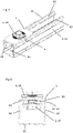
- the figures show an exemplary embodiment of a fastening arrangement according to the invention or its components.
- the fastening arrangement has a profile rail 6 , an attachment 5 and a connector 2 for attaching the attachment 5 to the profile rail 6 .
- the attachment has at least one through-opening 51 into which the connector 2 can be inserted.
- the attachment 5 can also have a plurality of similar through-openings 51 for connectors 2 .
- the attachment 5 can be attached to the profile rail 6 by means of a plurality of connectors 2, and/or the connector or connectors 2 can be spatially implemented on the attachment 5 for different applications.
- the attachment 5 is designed as a rail base.
- other versions of the add-on part 5 are also possible, as long as it has one or more through-openings 51 for the connector 2 .
- the profile rail 6 has a rail slot 69 running along the profile rail 6, through which access to the interior of the profile rail 6 is possible.
- the rail slot 69 is delimited by two rail lips 63 and 64, which form an undercut on which a rear-engagement element 27 of the connector 2, explained in more detail below, can be positively fixed.
- the profile rail 6 is designed as a C-profile rail and has a first side wall 61 and a second side wall 62 .
- the first rail lip 63 is located at the top of the first side wall 61 and protrudes from the first side wall 61 toward the second side wall 62 .
- the second rail lip 64 is located at the top of the second side wall 62 and protrudes from the second side wall 62 toward the first side wall 61 .
- the two side walls 61 and 62 are connected by a rail base 65 on the underside of the rail. In the illustrated embodiment, the two side walls 61 and 62 run parallel to one another and the rail base 65 is flat. In principle, however, other configurations are also conceivable, for example with a V-shaped rail base.
- the connector 2 has a gripping element 27 and a support element 20 , the gripping element 27 and the support element 20 being connected via a neck section 25 of the connector 2 .
- the rear gripping element 27 is elongate and has a width that is smaller than the width of the rail slot 69 and a length that is greater than the width of the rail slot 69 .
- the rear-engagement element 27 can thus be pushed through the rail slot 69 when the width of the rear-engagement element 27 runs parallel to the width of the rail slot 69 in an insertion position.
- the gripping element 27 is then rotated in the interior of the profile rail 6 about an axis running perpendicularly to the rail slot 69 into an anchoring position in which the length of the gripping element 27 runs parallel to the width of the rail slot 69, the gripping element 27 can no longer be pulled out of the rail slot 69 , so that the gripping element 27 and thus the connector 2 is anchored to the rail.
- the through-opening 51 in the attachment 5 is designed in such a way that the gripping element 27, at least in a predetermined orientation, and also the neck section 25, at least in some areas, can be inserted through the through-opening 51, specifically like this far until the support element 20 comes to rest on the attachment 5 and thus an even deeper insertion of the connector 2, ie the path of the connector 2, is limited.
- the connector 2 also has a fixing element 4 .
- This fixing element 4 has an annular frame 40 in which the support element 20 is embedded when the connector 2 is assembled.
- the inner cross section of the frame 40 preferably corresponds essentially to the outer cross section of the support element 20.
- the frame 40 On its upper side, the frame 40 has two finger recesses 43 and 44, which are arranged at opposite ends of the frame 40.
- the fixing element 4 also has two snap hooks 41 and 42 . These snap hooks 41 and 42 are located at opposite ends of the frame 40 on the underside of the frame 40 and protrude downward from the frame.
- the first snap hook 41 is arranged below the first finger recess 43 and the second snap hook 42 is arranged below the second finger recess 44 .
- the fixing element 4 is designed in one piece and as a plastic part, which means in particular the snap hooks 41 and 42 are designed integrally with the frame 40 .
- this is only to be understood as an example, and other configurations are also possible.
- Two indentations 31 and 32 are provided in the preferably metallic support element 20, each of these indentations 31 and 32 receiving a snap hook 41 and 42, respectively.
- connector 2 is used as in figure 7 shown inserted with the rear gripping element 27 first in a through-opening 51 in the attachment 5. Then, in particular by pressing on the finger recesses 43 and 44, the snap hooks 41 and 42 are pressed into the through-opening 51, where, as in FIG figure 8 shown, engage with the attachment 5 and thus fix the connector 2 in the pre-assembly position on the attachment 5.
- the attachment 5 together with the connector 2 is then arranged on the profile rail 6 and the rear-engagement element 27 in the insertion position is brought through the rail slot 69 into the interior of the profile rail 6, where the rear-engagement element 27 is then brought into the anchoring position and the attachment 5 is thus secured by means of the Connector 2 is anchored to the rail 6.
- the gripping element 27 is spring-actuated and pivotable relative to the support element 20 between the insertion position and the anchoring position. Accordingly, a spring and a connecting link for defining the pivoting path are arranged in the neck section 25 . But this can only be seen as an example. Basically Embodiments without a spring mechanism are also conceivable, or those in which the rear-engagement element 27 is arranged on the support element 20 in a torsionally rigid manner.
- figure 3 12 shows the snap hooks 41 and 42 arranged on a line 95 which runs along the rear gripping element 27 which is in the insertion position, which can be advantageous in terms of strength.
- a line 95 which runs along the rear gripping element 27 which is in the insertion position
- the fixing element 4 also has a snap mechanism for the support element 20 .
- This snap mechanism for the support element 20 is formed by latching webs 48 and 49 which are arranged on the first snap hook 41 and the second snap hook 42, respectively.
- the latching webs 48 or 49 snap into place on the underside of the support element 20 facing the add-on part 5 in the region of the first indentation 31 or the second indentation 32 .
- the fixing element 4 With its snap mechanism formed by the snap hooks 41 and 42, the fixing element 4 provides sufficiently high holding forces for the attachment 5 so that the connector 2 can withstand the forces that typically occur during assembly and preferably also when transporting a combination of connector 2 and attachment 5 reliably remains in the pre-assembly position. However, it may be necessary to release the connector 2 from the pre-assembly position, for example if the connector 2 is to be arranged at another through-opening 51 of the same attachment 5 or another attachment.
Landscapes
- Engineering & Computer Science (AREA)
- General Engineering & Computer Science (AREA)
- Mechanical Engineering (AREA)
- Insertion Pins And Rivets (AREA)
- Connection Of Plates (AREA)
- Connector Housings Or Holding Contact Members (AREA)
Claims (15)
- Raccord (2) permettant de raccorder une pièce de montage (5) présentant une ouverture traversante (51) à un rail profilé (6) présentant une fente de rail (69), comportant- un élément de mise en prise arrière (27) permettant d'ancrer le raccord (2) à la fente de rail (69) du rail profilé (6), et comportant- un élément d'appui (20) relié à l'élément de mise en prise arrière (27) et permettant l'appui sur la pièce de montage (5) à proximité de l'ouverture traversante (51) de la pièce de montage (5) afin de limiter une course du raccord (2) à travers l'ouverture traversante (51) de la pièce de montage (5),caractérisé en ceque le raccord (2) présente au moins un élément de fixation (4) au moyen duquel le raccord (2) peut être fixé à la pièce de montage (5) dans une position de prémontage dans laquelle le raccord pénètre dans l'ouverture traversante (51) de la pièce de montage (5), etque l'élément de fixation (4) présente un cadre (40) annulaire dans lequel est logé l'élément d'appui (20).
- Raccord (2) selon la revendication 1,
caractérisé en ce
que le raccord (2) peut être fixé de manière amovible à la pièce de montage (5) dans la position de prémontage au moyen de l'élément de fixation (4). - Raccord (2) selon l'une des revendications précédentes,
caractérisé en ce
que l'élément de fixation (4) est une pièce séparée. - Raccord (2) selon l'une des revendications précédentes,
caractérisé en ce
que l'élément de fixation (4) est disposé sur l'élément d'appui (20). - Raccord (2) selon l'une des revendications précédentes,
caractérisé en ce
que l'élément d'appui (20) repose sur la pièce de montage (5) dans la position de prémontage. - Raccord (2) selon l'une des revendications précédentes,
caractérisé en ceque l'élément de fixation (4) forme un mécanisme d'encliquetage pour la pièce de montage (5), lequel agit sur l'ouverture traversante (51) de la pièce de montage (5) et/ouque l'élément de fixation (4) forme un mécanisme d'encliquetage pour l'élément de support (20). - Raccord (2) selon l'une des revendications précédentes,
caractérisé en ce
que l'élément de fixation (4) présente au moins un crochet d'encliquetage (41, 42). - Raccord (2) selon l'une des revendications précédentes,
caractérisé en ce
que l'élément de fixation (4) présente au moins un évidement (43, 44) pour les doigts. - Raccord (2) selon les revendications 7 et 8,
caractérisé en ce
que l'évidement (43 ou 44) pour les doigts est disposé au-dessus du crochet d'encliquetage (41 ou 42). - Raccord (2) selon la revendication 7 ou 9,
caractérisé en ce
que l'élément d'appui (20) présente au moins un renfoncement (31 ou 32) permettant de recevoir le crochet d'encliquetage (41 ou 42). - Raccord (2) selon l'une des revendications précédentes,
caractérisé en ce
que l'élément de fixation (4) présente deux crochets d'encliquetage (41, 42) disposés sur des côtés opposés du cadre (40). - Raccord (2) selon la revendication 6,
caractérisé en ce
que le raccord (2) présente un mécanisme permettant de réduire une force de maintien du mécanisme d'encliquetage pour la pièce de montage (5). - Raccord (2) selon l'une des revendications précédentes,
caractérisé en ce
que l'élément de fixation (4) est une pièce en matière plastique. - Raccord (2) selon l'une des revendications précédentes,
caractérisé en ce
que l'élément de mise en prise arrière (27) peut pivoter par rapport à l'élément d'appui (20) entre une position d'insertion permettant l'insertion dans la fente de rail (69) et une position d'ancrage permettant la mise en prise par l'arrière de la fente de rail (69). - Agencement de fixation comportant une pièce de montage (5) présentant une ouverture traversante (51), comportant un raccord (2) selon l'une des revendications précédentes permettant de raccorder la pièce de montage (5) à un rail profilé (6) présentant une fente de rail (69), et de préférence comportant également ledit rail profilé (6).
Applications Claiming Priority (2)
| Application Number | Priority Date | Filing Date | Title |
|---|---|---|---|
| EP17191576.2A EP3456990A1 (fr) | 2017-09-18 | 2017-09-18 | Connecteur pourvu d'élément de fixation pour pièce rapportée |
| PCT/EP2018/073669 WO2019052847A1 (fr) | 2017-09-18 | 2018-09-04 | Raccord doté d'un élément de fixation pour une pièce de montage |
Publications (2)
| Publication Number | Publication Date |
|---|---|
| EP3685057A1 EP3685057A1 (fr) | 2020-07-29 |
| EP3685057B1 true EP3685057B1 (fr) | 2022-08-10 |
Family
ID=59901423
Family Applications (2)
| Application Number | Title | Priority Date | Filing Date |
|---|---|---|---|
| EP17191576.2A Withdrawn EP3456990A1 (fr) | 2017-09-18 | 2017-09-18 | Connecteur pourvu d'élément de fixation pour pièce rapportée |
| EP18765105.4A Active EP3685057B1 (fr) | 2017-09-18 | 2018-09-04 | Connecteur pourvu d'élément de fixation pour pièce rapportée |
Family Applications Before (1)
| Application Number | Title | Priority Date | Filing Date |
|---|---|---|---|
| EP17191576.2A Withdrawn EP3456990A1 (fr) | 2017-09-18 | 2017-09-18 | Connecteur pourvu d'élément de fixation pour pièce rapportée |
Country Status (4)
| Country | Link |
|---|---|
| EP (2) | EP3456990A1 (fr) |
| JP (1) | JP7046165B2 (fr) |
| KR (1) | KR102642679B1 (fr) |
| WO (1) | WO2019052847A1 (fr) |
Families Citing this family (16)
| Publication number | Priority date | Publication date | Assignee | Title |
|---|---|---|---|---|
| US20180238041A1 (en) | 2017-02-21 | 2018-08-23 | Styrc Jacek | Modular furniture system |
| USD887025S1 (en) | 2017-11-17 | 2020-06-09 | 2724889 Ontario Inc. | Connector for a modular structure |
| USD952384S1 (en) | 2020-02-04 | 2022-05-24 | 2724889 Ontario Inc. | Leg |
| USD936859S1 (en) | 2020-02-04 | 2021-11-23 | 2724889 Ontario Inc. | Connector |
| USD938770S1 (en) * | 2020-02-04 | 2021-12-21 | 2724889 Ontario Inc. | Connector |
| USD952382S1 (en) | 2020-02-04 | 2022-05-24 | 2724889 Ontario Inc. | Table |
| USD938771S1 (en) * | 2020-02-04 | 2021-12-21 | 2724889 Ontario Inc. | Connector |
| USD938772S1 (en) * | 2020-02-04 | 2021-12-21 | 2724889 Ontario Inc. | Connector |
| USD936247S1 (en) | 2020-08-12 | 2021-11-16 | 2724889 Ontario Inc. | Connector for a modular structure |
| USD938619S1 (en) | 2020-08-12 | 2021-12-14 | 2724889 Ontario Inc. | Connector for a modular structure |
| USD939106S1 (en) | 2020-08-12 | 2021-12-21 | 2724889 Ontario Inc. | Connector for a modular structure |
| USD939731S1 (en) | 2020-08-12 | 2021-12-28 | 2724889 Ontario Inc. | Connector for a modular structure |
| USD936861S1 (en) | 2020-08-12 | 2021-11-23 | 2724889 Ontario Inc. | Connector for a modular structure |
| USD936246S1 (en) | 2020-08-12 | 2021-11-16 | 2724889 Ontario Inc. | Connector for a modular structure |
| USD938068S1 (en) | 2020-08-12 | 2021-12-07 | 2724889 Ontario Inc. | Connector for a modular structure |
| USD1039960S1 (en) | 2022-09-29 | 2024-08-27 | Canadian Tire Corporation, Limited | Channel fastener clip |
Family Cites Families (15)
| Publication number | Priority date | Publication date | Assignee | Title |
|---|---|---|---|---|
| GB1579941A (en) | 1977-02-03 | 1980-11-26 | Bicc Ltd | Screw fixing |
| DE4421252A1 (de) * | 1994-06-17 | 1995-12-21 | Hilti Ag | Befestigungsvorrichtung |
| DE4432996A1 (de) * | 1994-09-16 | 1996-03-21 | Hilti Ag | Befestigungsmutter für Profilschienen |
| JPH08123329A (ja) * | 1994-10-26 | 1996-05-17 | Nippon Light Metal Co Ltd | 取付部材 |
| JP2000002208A (ja) | 1998-06-12 | 2000-01-07 | Atom Medical Corp | 器具等の支持部材の固定装置 |
| DE10052577A1 (de) | 2000-10-23 | 2002-04-25 | Hilti Ag | Montagewinkel für Schienen |
| JP2002147426A (ja) * | 2000-11-07 | 2002-05-22 | Nakai Kogyo Kk | ナット保持構造及びボルト保持構造 |
| DE10256861A1 (de) | 2002-12-05 | 2004-06-24 | Hilti Ag | Befestigungssystem |
| NL1029499C2 (nl) | 2005-07-12 | 2007-01-15 | Walraven Holding Bv J Van | Bevestigingssamenstel. |
| DE102009000786A1 (de) | 2009-02-11 | 2010-08-19 | Hilti Aktiengesellschaft | Befestigungsvorrichtung zur Anordnung an einer Montageschiene |
| FR2962503B3 (fr) * | 2010-07-09 | 2012-08-10 | Trw Automotive Electron & Comp | Ensemble de fixation |
| DE102012209272A1 (de) | 2012-06-01 | 2013-12-05 | Hilti Aktiengesellschaft | Befestigungsvorrichtung für Solarpaneele |
| DE102014110192A1 (de) | 2014-07-21 | 2016-01-21 | Fischerwerke Gmbh & Co. Kg | Befestiger für eine Montageschiene |
| DE102015118314A1 (de) | 2014-12-09 | 2016-06-09 | Fischerwerke Gmbh & Co. Kg | Verfahren zum Befestigen eines Befestigungselements an einer Montageschiene sowie Befestigungselement |
| JP2016116321A (ja) * | 2014-12-15 | 2016-06-23 | 正勝 太西 | 締付け固定具 |
-
2017
- 2017-09-18 EP EP17191576.2A patent/EP3456990A1/fr not_active Withdrawn
-
2018
- 2018-09-04 KR KR1020207005040A patent/KR102642679B1/ko active Active
- 2018-09-04 JP JP2020515038A patent/JP7046165B2/ja active Active
- 2018-09-04 WO PCT/EP2018/073669 patent/WO2019052847A1/fr not_active Ceased
- 2018-09-04 EP EP18765105.4A patent/EP3685057B1/fr active Active
Also Published As
| Publication number | Publication date |
|---|---|
| KR20200051589A (ko) | 2020-05-13 |
| EP3456990A1 (fr) | 2019-03-20 |
| KR102642679B1 (ko) | 2024-02-29 |
| JP2020533541A (ja) | 2020-11-19 |
| JP7046165B2 (ja) | 2022-04-01 |
| WO2019052847A1 (fr) | 2019-03-21 |
| EP3685057A1 (fr) | 2020-07-29 |
Similar Documents
| Publication | Publication Date | Title |
|---|---|---|
| EP3685057B1 (fr) | Connecteur pourvu d'élément de fixation pour pièce rapportée | |
| EP3585211B1 (fr) | Arrangement avec des pieces de fournitures et un element de connection | |
| DE102008032964B4 (de) | Gassackanordnung für ein Fahrzeuginsassen-Rückhaltesystem | |
| EP2807383B1 (fr) | Système de fixation | |
| EP3529503B1 (fr) | Dispositif de fixation servant à fixer un élément de retenue à un support et système comportant un dispositif de fixation et un élément de retenue | |
| DE102014005286B3 (de) | Befestigungsvorrichtung, Aufhängevorrichtung und Verfahren zum Montieren einer Aufhängevorrichtung | |
| DE102010036894A1 (de) | Federkörper | |
| DE202007008610U1 (de) | Befestigungssystem | |
| WO2017016652A1 (fr) | Dispositif de fixation pour relier de façon amovible un panneau à une structure, panneau de recouvrement pour coussin gonflable et véhicule équipé d'une structure et d'un coussin gonflable | |
| WO2010034486A1 (fr) | Dispositif de fixation | |
| EP2139727A1 (fr) | Dispositif de fixation et outil de verrouillage d'un élément de fixation | |
| EP3622153A1 (fr) | Commande de meuble à moteur | |
| WO2015144794A2 (fr) | Dispositif d'étanchéité et moyen de fixation | |
| EP1852304B1 (fr) | Dispositif de fixation doté d'un cliquet amovible | |
| DE19948165B4 (de) | Anordnung zur lösbaren Befestigung eines Bauteils an einer Wand | |
| DE102019205830A1 (de) | Befestigungselement und Befestigungsanordnung für eine Kraftfahrzeugkarosserie | |
| EP2994650B1 (fr) | Élément de fixation pour la connection d'un support de transmission à un élément de levier | |
| DE102009058815B4 (de) | Haltevorrichtung für Anbauteile von Fahrzeugen | |
| DE102009034584A1 (de) | Befestigungseinrichtung für einen Gurtbandumlenker | |
| DE102006061617A1 (de) | Befestigungsanordnung, insbesondere zum Halten eines Umlenkbeschlags für einen Gurtbandabschnitt eines Sicherheitsgurtes in einem Fahrzeug, sowie Verfahren zum Befestigen eines Umlenkbeschlags an einer Trägerwand | |
| DE10349878B4 (de) | Befestigungseinrichtung an einer Fahrzeugkarosserie und entsprechende Fahrzeugkarosserie | |
| EP1666736B1 (fr) | Attache de retenue pour carrosseries automobiles | |
| DE102006041803B4 (de) | Vorrichtung zur Befestigung eines Gerätes an einer Tragschiene | |
| DE102015009367A1 (de) | Befestiger zum lösbaren Verbinden eines Paneels an einer Struktur, Abdeckpaneel für ein Airbag und Fahrzeug mit einer Struktur und einem Airbag | |
| DE102005062979A1 (de) | Befestigungseinheit mit einem Befestigungselement |
Legal Events
| Date | Code | Title | Description |
|---|---|---|---|
| STAA | Information on the status of an ep patent application or granted ep patent |
Free format text: STATUS: UNKNOWN |
|
| STAA | Information on the status of an ep patent application or granted ep patent |
Free format text: STATUS: THE INTERNATIONAL PUBLICATION HAS BEEN MADE |
|
| PUAI | Public reference made under article 153(3) epc to a published international application that has entered the european phase |
Free format text: ORIGINAL CODE: 0009012 |
|
| STAA | Information on the status of an ep patent application or granted ep patent |
Free format text: STATUS: REQUEST FOR EXAMINATION WAS MADE |
|
| 17P | Request for examination filed |
Effective date: 20200420 |
|
| AK | Designated contracting states |
Kind code of ref document: A1 Designated state(s): AL AT BE BG CH CY CZ DE DK EE ES FI FR GB GR HR HU IE IS IT LI LT LU LV MC MK MT NL NO PL PT RO RS SE SI SK SM TR |
|
| AX | Request for extension of the european patent |
Extension state: BA ME |
|
| DAV | Request for validation of the european patent (deleted) | ||
| DAX | Request for extension of the european patent (deleted) | ||
| REG | Reference to a national code |
Ref country code: HK Ref legal event code: DE Ref document number: 40025651 Country of ref document: HK |
|
| GRAP | Despatch of communication of intention to grant a patent |
Free format text: ORIGINAL CODE: EPIDOSNIGR1 |
|
| STAA | Information on the status of an ep patent application or granted ep patent |
Free format text: STATUS: GRANT OF PATENT IS INTENDED |
|
| INTG | Intention to grant announced |
Effective date: 20220518 |
|
| GRAS | Grant fee paid |
Free format text: ORIGINAL CODE: EPIDOSNIGR3 |
|
| GRAA | (expected) grant |
Free format text: ORIGINAL CODE: 0009210 |
|
| STAA | Information on the status of an ep patent application or granted ep patent |
Free format text: STATUS: THE PATENT HAS BEEN GRANTED |
|
| AK | Designated contracting states |
Kind code of ref document: B1 Designated state(s): AL AT BE BG CH CY CZ DE DK EE ES FI FR GB GR HR HU IE IS IT LI LT LU LV MC MK MT NL NO PL PT RO RS SE SI SK SM TR |
|
| REG | Reference to a national code |
Ref country code: AT Ref legal event code: REF Ref document number: 1510748 Country of ref document: AT Kind code of ref document: T Effective date: 20220815 Ref country code: CH Ref legal event code: EP |
|
| REG | Reference to a national code |
Ref country code: DE Ref legal event code: R096 Ref document number: 502018010375 Country of ref document: DE |
|
| REG | Reference to a national code |
Ref country code: IE Ref legal event code: FG4D Free format text: LANGUAGE OF EP DOCUMENT: GERMAN |
|
| REG | Reference to a national code |
Ref country code: SE Ref legal event code: TRGR |
|
| REG | Reference to a national code |
Ref country code: NL Ref legal event code: MP Effective date: 20220810 |
|
| REG | Reference to a national code |
Ref country code: LT Ref legal event code: MG9D |
|
| PG25 | Lapsed in a contracting state [announced via postgrant information from national office to epo] |
Ref country code: RS Free format text: LAPSE BECAUSE OF FAILURE TO SUBMIT A TRANSLATION OF THE DESCRIPTION OR TO PAY THE FEE WITHIN THE PRESCRIBED TIME-LIMIT Effective date: 20220810 Ref country code: PT Free format text: LAPSE BECAUSE OF FAILURE TO SUBMIT A TRANSLATION OF THE DESCRIPTION OR TO PAY THE FEE WITHIN THE PRESCRIBED TIME-LIMIT Effective date: 20221212 Ref country code: NO Free format text: LAPSE BECAUSE OF FAILURE TO SUBMIT A TRANSLATION OF THE DESCRIPTION OR TO PAY THE FEE WITHIN THE PRESCRIBED TIME-LIMIT Effective date: 20221110 Ref country code: NL Free format text: LAPSE BECAUSE OF FAILURE TO SUBMIT A TRANSLATION OF THE DESCRIPTION OR TO PAY THE FEE WITHIN THE PRESCRIBED TIME-LIMIT Effective date: 20220810 Ref country code: LV Free format text: LAPSE BECAUSE OF FAILURE TO SUBMIT A TRANSLATION OF THE DESCRIPTION OR TO PAY THE FEE WITHIN THE PRESCRIBED TIME-LIMIT Effective date: 20220810 Ref country code: LT Free format text: LAPSE BECAUSE OF FAILURE TO SUBMIT A TRANSLATION OF THE DESCRIPTION OR TO PAY THE FEE WITHIN THE PRESCRIBED TIME-LIMIT Effective date: 20220810 Ref country code: FI Free format text: LAPSE BECAUSE OF FAILURE TO SUBMIT A TRANSLATION OF THE DESCRIPTION OR TO PAY THE FEE WITHIN THE PRESCRIBED TIME-LIMIT Effective date: 20220810 |
|
| PG25 | Lapsed in a contracting state [announced via postgrant information from national office to epo] |
Ref country code: PL Free format text: LAPSE BECAUSE OF FAILURE TO SUBMIT A TRANSLATION OF THE DESCRIPTION OR TO PAY THE FEE WITHIN THE PRESCRIBED TIME-LIMIT Effective date: 20220810 Ref country code: IS Free format text: LAPSE BECAUSE OF FAILURE TO SUBMIT A TRANSLATION OF THE DESCRIPTION OR TO PAY THE FEE WITHIN THE PRESCRIBED TIME-LIMIT Effective date: 20221210 Ref country code: HR Free format text: LAPSE BECAUSE OF FAILURE TO SUBMIT A TRANSLATION OF THE DESCRIPTION OR TO PAY THE FEE WITHIN THE PRESCRIBED TIME-LIMIT Effective date: 20220810 Ref country code: GR Free format text: LAPSE BECAUSE OF FAILURE TO SUBMIT A TRANSLATION OF THE DESCRIPTION OR TO PAY THE FEE WITHIN THE PRESCRIBED TIME-LIMIT Effective date: 20221111 |
|
| PG25 | Lapsed in a contracting state [announced via postgrant information from national office to epo] |
Ref country code: SM Free format text: LAPSE BECAUSE OF FAILURE TO SUBMIT A TRANSLATION OF THE DESCRIPTION OR TO PAY THE FEE WITHIN THE PRESCRIBED TIME-LIMIT Effective date: 20220810 Ref country code: RO Free format text: LAPSE BECAUSE OF FAILURE TO SUBMIT A TRANSLATION OF THE DESCRIPTION OR TO PAY THE FEE WITHIN THE PRESCRIBED TIME-LIMIT Effective date: 20220810 Ref country code: ES Free format text: LAPSE BECAUSE OF FAILURE TO SUBMIT A TRANSLATION OF THE DESCRIPTION OR TO PAY THE FEE WITHIN THE PRESCRIBED TIME-LIMIT Effective date: 20220810 Ref country code: DK Free format text: LAPSE BECAUSE OF FAILURE TO SUBMIT A TRANSLATION OF THE DESCRIPTION OR TO PAY THE FEE WITHIN THE PRESCRIBED TIME-LIMIT Effective date: 20220810 Ref country code: CZ Free format text: LAPSE BECAUSE OF FAILURE TO SUBMIT A TRANSLATION OF THE DESCRIPTION OR TO PAY THE FEE WITHIN THE PRESCRIBED TIME-LIMIT Effective date: 20220810 |
|
| REG | Reference to a national code |
Ref country code: DE Ref legal event code: R097 Ref document number: 502018010375 Country of ref document: DE |
|
| REG | Reference to a national code |
Ref country code: BE Ref legal event code: MM Effective date: 20220930 |
|
| PG25 | Lapsed in a contracting state [announced via postgrant information from national office to epo] |
Ref country code: SK Free format text: LAPSE BECAUSE OF FAILURE TO SUBMIT A TRANSLATION OF THE DESCRIPTION OR TO PAY THE FEE WITHIN THE PRESCRIBED TIME-LIMIT Effective date: 20220810 Ref country code: MC Free format text: LAPSE BECAUSE OF FAILURE TO SUBMIT A TRANSLATION OF THE DESCRIPTION OR TO PAY THE FEE WITHIN THE PRESCRIBED TIME-LIMIT Effective date: 20220810 Ref country code: EE Free format text: LAPSE BECAUSE OF FAILURE TO SUBMIT A TRANSLATION OF THE DESCRIPTION OR TO PAY THE FEE WITHIN THE PRESCRIBED TIME-LIMIT Effective date: 20220810 |
|
| PLBE | No opposition filed within time limit |
Free format text: ORIGINAL CODE: 0009261 |
|
| STAA | Information on the status of an ep patent application or granted ep patent |
Free format text: STATUS: NO OPPOSITION FILED WITHIN TIME LIMIT |
|
| PG25 | Lapsed in a contracting state [announced via postgrant information from national office to epo] |
Ref country code: LU Free format text: LAPSE BECAUSE OF NON-PAYMENT OF DUE FEES Effective date: 20220904 Ref country code: AL Free format text: LAPSE BECAUSE OF FAILURE TO SUBMIT A TRANSLATION OF THE DESCRIPTION OR TO PAY THE FEE WITHIN THE PRESCRIBED TIME-LIMIT Effective date: 20220810 |
|
| 26N | No opposition filed |
Effective date: 20230511 |
|
| GBPC | Gb: european patent ceased through non-payment of renewal fee |
Effective date: 20221110 |
|
| PG25 | Lapsed in a contracting state [announced via postgrant information from national office to epo] |
Ref country code: IE Free format text: LAPSE BECAUSE OF NON-PAYMENT OF DUE FEES Effective date: 20220904 |
|
| PG25 | Lapsed in a contracting state [announced via postgrant information from national office to epo] |
Ref country code: SI Free format text: LAPSE BECAUSE OF FAILURE TO SUBMIT A TRANSLATION OF THE DESCRIPTION OR TO PAY THE FEE WITHIN THE PRESCRIBED TIME-LIMIT Effective date: 20220810 |
|
| PG25 | Lapsed in a contracting state [announced via postgrant information from national office to epo] |
Ref country code: BE Free format text: LAPSE BECAUSE OF NON-PAYMENT OF DUE FEES Effective date: 20220930 |
|
| PG25 | Lapsed in a contracting state [announced via postgrant information from national office to epo] |
Ref country code: GB Free format text: LAPSE BECAUSE OF NON-PAYMENT OF DUE FEES Effective date: 20221110 |
|
| PG25 | Lapsed in a contracting state [announced via postgrant information from national office to epo] |
Ref country code: CY Free format text: LAPSE BECAUSE OF FAILURE TO SUBMIT A TRANSLATION OF THE DESCRIPTION OR TO PAY THE FEE WITHIN THE PRESCRIBED TIME-LIMIT Effective date: 20220810 |
|
| PG25 | Lapsed in a contracting state [announced via postgrant information from national office to epo] |
Ref country code: MK Free format text: LAPSE BECAUSE OF FAILURE TO SUBMIT A TRANSLATION OF THE DESCRIPTION OR TO PAY THE FEE WITHIN THE PRESCRIBED TIME-LIMIT Effective date: 20220810 Ref country code: HU Free format text: LAPSE BECAUSE OF FAILURE TO SUBMIT A TRANSLATION OF THE DESCRIPTION OR TO PAY THE FEE WITHIN THE PRESCRIBED TIME-LIMIT; INVALID AB INITIO Effective date: 20180904 |
|
| PG25 | Lapsed in a contracting state [announced via postgrant information from national office to epo] |
Ref country code: BG Free format text: LAPSE BECAUSE OF FAILURE TO SUBMIT A TRANSLATION OF THE DESCRIPTION OR TO PAY THE FEE WITHIN THE PRESCRIBED TIME-LIMIT Effective date: 20220810 |
|
| PG25 | Lapsed in a contracting state [announced via postgrant information from national office to epo] |
Ref country code: MT Free format text: LAPSE BECAUSE OF FAILURE TO SUBMIT A TRANSLATION OF THE DESCRIPTION OR TO PAY THE FEE WITHIN THE PRESCRIBED TIME-LIMIT Effective date: 20220810 |
|
| REG | Reference to a national code |
Ref country code: CH Ref legal event code: U11 Free format text: ST27 STATUS EVENT CODE: U-0-0-U10-U11 (AS PROVIDED BY THE NATIONAL OFFICE) Effective date: 20251001 |
|
| PGFP | Annual fee paid to national office [announced via postgrant information from national office to epo] |
Ref country code: DE Payment date: 20250919 Year of fee payment: 8 |
|
| PGFP | Annual fee paid to national office [announced via postgrant information from national office to epo] |
Ref country code: IT Payment date: 20250923 Year of fee payment: 8 |
|
| PGFP | Annual fee paid to national office [announced via postgrant information from national office to epo] |
Ref country code: FR Payment date: 20250922 Year of fee payment: 8 Ref country code: AT Payment date: 20250919 Year of fee payment: 8 |
|
| PGFP | Annual fee paid to national office [announced via postgrant information from national office to epo] |
Ref country code: SE Payment date: 20250918 Year of fee payment: 8 |
|
| PG25 | Lapsed in a contracting state [announced via postgrant information from national office to epo] |
Ref country code: TR Free format text: LAPSE BECAUSE OF FAILURE TO SUBMIT A TRANSLATION OF THE DESCRIPTION OR TO PAY THE FEE WITHIN THE PRESCRIBED TIME-LIMIT Effective date: 20220810 |
|
| PGFP | Annual fee paid to national office [announced via postgrant information from national office to epo] |
Ref country code: CH Payment date: 20251001 Year of fee payment: 8 |