EP3685302B1 - Systèmes rfid - Google Patents
Systèmes rfid Download PDFInfo
- Publication number
- EP3685302B1 EP3685302B1 EP18779746.9A EP18779746A EP3685302B1 EP 3685302 B1 EP3685302 B1 EP 3685302B1 EP 18779746 A EP18779746 A EP 18779746A EP 3685302 B1 EP3685302 B1 EP 3685302B1
- Authority
- EP
- European Patent Office
- Prior art keywords
- antenna
- signal
- subsystems
- signals
- twisted pair
- Prior art date
- Legal status (The legal status is an assumption and is not a legal conclusion. Google has not performed a legal analysis and makes no representation as to the accuracy of the status listed.)
- Active
Links
Images


Classifications
-
- H—ELECTRICITY
- H04—ELECTRIC COMMUNICATION TECHNIQUE
- H04B—TRANSMISSION
- H04B1/00—Details of transmission systems, not covered by a single one of groups H04B3/00 - H04B13/00; Details of transmission systems not characterised by the medium used for transmission
- H04B1/69—Spread spectrum techniques
- H04B1/713—Spread spectrum techniques using frequency hopping
-
- G—PHYSICS
- G06—COMPUTING OR CALCULATING; COUNTING
- G06K—GRAPHICAL DATA READING; PRESENTATION OF DATA; RECORD CARRIERS; HANDLING RECORD CARRIERS
- G06K7/00—Methods or arrangements for sensing record carriers, e.g. for reading patterns
- G06K7/0008—General problems related to the reading of electronic memory record carriers, independent of its reading method, e.g. power transfer
-
- G—PHYSICS
- G06—COMPUTING OR CALCULATING; COUNTING
- G06K—GRAPHICAL DATA READING; PRESENTATION OF DATA; RECORD CARRIERS; HANDLING RECORD CARRIERS
- G06K7/00—Methods or arrangements for sensing record carriers, e.g. for reading patterns
- G06K7/10—Methods or arrangements for sensing record carriers, e.g. for reading patterns by electromagnetic radiation, e.g. optical sensing; by corpuscular radiation
- G06K7/10009—Methods or arrangements for sensing record carriers, e.g. for reading patterns by electromagnetic radiation, e.g. optical sensing; by corpuscular radiation sensing by radiation using wavelengths larger than 0.1 mm, e.g. radio-waves or microwaves
- G06K7/10297—Methods or arrangements for sensing record carriers, e.g. for reading patterns by electromagnetic radiation, e.g. optical sensing; by corpuscular radiation sensing by radiation using wavelengths larger than 0.1 mm, e.g. radio-waves or microwaves arrangements for handling protocols designed for non-contact record carriers such as RFIDs NFCs, e.g. ISO/IEC 14443 and 18092
-
- G—PHYSICS
- G06—COMPUTING OR CALCULATING; COUNTING
- G06K—GRAPHICAL DATA READING; PRESENTATION OF DATA; RECORD CARRIERS; HANDLING RECORD CARRIERS
- G06K7/00—Methods or arrangements for sensing record carriers, e.g. for reading patterns
- G06K7/10—Methods or arrangements for sensing record carriers, e.g. for reading patterns by electromagnetic radiation, e.g. optical sensing; by corpuscular radiation
- G06K7/10009—Methods or arrangements for sensing record carriers, e.g. for reading patterns by electromagnetic radiation, e.g. optical sensing; by corpuscular radiation sensing by radiation using wavelengths larger than 0.1 mm, e.g. radio-waves or microwaves
- G06K7/10316—Methods or arrangements for sensing record carriers, e.g. for reading patterns by electromagnetic radiation, e.g. optical sensing; by corpuscular radiation sensing by radiation using wavelengths larger than 0.1 mm, e.g. radio-waves or microwaves using at least one antenna particularly designed for interrogating the wireless record carriers
- G06K7/10356—Methods or arrangements for sensing record carriers, e.g. for reading patterns by electromagnetic radiation, e.g. optical sensing; by corpuscular radiation sensing by radiation using wavelengths larger than 0.1 mm, e.g. radio-waves or microwaves using at least one antenna particularly designed for interrogating the wireless record carriers using a plurality of antennas, e.g. configurations including means to resolve interference between the plurality of antennas
-
- G—PHYSICS
- G06—COMPUTING OR CALCULATING; COUNTING
- G06K—GRAPHICAL DATA READING; PRESENTATION OF DATA; RECORD CARRIERS; HANDLING RECORD CARRIERS
- G06K7/00—Methods or arrangements for sensing record carriers, e.g. for reading patterns
- G06K7/10—Methods or arrangements for sensing record carriers, e.g. for reading patterns by electromagnetic radiation, e.g. optical sensing; by corpuscular radiation
- G06K7/10009—Methods or arrangements for sensing record carriers, e.g. for reading patterns by electromagnetic radiation, e.g. optical sensing; by corpuscular radiation sensing by radiation using wavelengths larger than 0.1 mm, e.g. radio-waves or microwaves
- G06K7/10366—Methods or arrangements for sensing record carriers, e.g. for reading patterns by electromagnetic radiation, e.g. optical sensing; by corpuscular radiation sensing by radiation using wavelengths larger than 0.1 mm, e.g. radio-waves or microwaves the interrogation device being adapted for miscellaneous applications
- G06K7/10475—Methods or arrangements for sensing record carriers, e.g. for reading patterns by electromagnetic radiation, e.g. optical sensing; by corpuscular radiation sensing by radiation using wavelengths larger than 0.1 mm, e.g. radio-waves or microwaves the interrogation device being adapted for miscellaneous applications arrangements to facilitate interaction with further interrogation devices, e.g. such that at least two interrogation devices may function and cooperate in a network of such devices
Definitions
- UHF ultra-high frequency
- RFID interrogators often use multiple antennas to give a wider area of coverage either through antenna diversity, or by exploiting the coherent power sum of multicast signals. Details can be found, for example in: WO2007/094868 , WO2008/118875 , WO2008/027650 , WO2011/135329 and US 2009/0146792 . Further background prior art can be found in WO2011/135328 .
- the RF carrier has a substantially higher frequency in the UHF band chosen to avoid interference with other services, to conform to regulatory requirements and to allow radiative transmission.
- the RF carrier frequency may be altered within a set of predefined channels to mitigate the effects of multipath fading and reduce interference.
- UHF Ultra High Frequency
- the RF frontend is connected to the antennas by some form of a transmission line. In some systems this is a microstrip on a printed circuit board; in other cases a co-axial cable.
- the attenuation of the transmission line limits the separation between the RF front end and the antenna.
- a typical limit on the separation for low loss co-axial cables is of the order of 10 metres. Beyond this distance, significantly more power is required in the downlink of the RF front end and uplink sensitivity is degraded due to the increase in Signal to Noise Ratio (SNR) on the cable.
- SNR Signal to Noise Ratio
- the document further discloses that an exciter network interface and control process, which provides the control messages, and manages communication protocols.
- the document further discloses a wired connection that may be a coaxial cable, and that a control signal is modulated at a first RF frequency.
- the document further discloses that a wired connection may be a twisted pair cable, and a control signal is a baseband signal.
- a control signal may be modulated at a first RF frequency, and the exciter is configured to down convert the control signal to extract at least the identity of the exciter identified by the control signal.
- the invention is set out in claim 1 that defines a system comprising a plurality of antenna subsystems, each antenna subsystem comprising an antenna and an oscillator, the system for the distribution of RFID signals to each of the antennas.
- Preferred embodiments are defined in the dependent claims.
- the system may comprise a central control module to generate signals and control the protocol operations.
- the system may further comprise a cable connecting the central module to one or more antenna subsystems carrying substantially baseband representations of reader to tag modulation and tag to reader modulation.
- a timing reference signal is transmitted over a pair of the cable, to one or more antenna subsystems to phase lock the frequency conversion oscillators of the system.
- a separate cable may be used between the central module and each antenna subsystem of the system.
- a separate cable may be used between the central module and each antenna subsystem, and where multiple antenna subsystems are daisy-chained from a single cable from the central control module, to link the central control module to the antennas.
- an antenna unit may be a unit or module which connects to an antenna such as a transmit or receive antenna, or antenna network, and sends signals to and/or receives signals from the antenna.
- the antenna unit may process the signals for transmission and/or reception.
- the configurable filter is implemented by means of a switched filter bank.
- the uplink (tag to reader) signals are carried at a (low) IF frequency, with multiple, i.e. different respective antenna subsystems each utilising a different respective IF frequency to allow separation of the signals from each antenna subsystem at the central controller.
- the distributed RFID interrogator system comprises a central controller 108 and multiple antenna units (105 ⁇ a,b,c,d,e ⁇ ).
- Each antenna unit comprises an antenna (106 ⁇ a,b,c,d,e ⁇ ) with cables (1 07 ⁇ a,w,x,y,z ⁇ ) connecting the antenna units to the central controller 108.
- FIG. 4 shows an example of RFID system using a twisted pair cable for antenna remoting.
- the RFID system comprising a central controller 124, a twisted pair cable 121 connected to an antenna unit 123 feeding the antenna 122.
- the central controller 124 comprises a digital baseband unit 117 and analog baseband unit 118.
- the antenna unit 123 comprises an RF front end 119 and RF synthesiser 120.
- the baseband transmit signals are generated in the digital baseband unit 117 based on local regulations and standards. After digital to analog conversion, the resulting analog baseband signals are transmitted to the remote antenna subsystem 123 over a twisted-pair cable 121. Up-conversion is performed in the RF front end 119. A short coaxial cable can be applied between the antenna and the antenna subsystem depending on requirements of the installation.
- the backscattered signals, in the reverse link, experience similar processes but in a reverse order. They are received as RF at the antenna, and mixed back to I and Q baseband components in the antenna subsystem before transmission over the two pairs of the Cat5e to the central controller where digitization and protocol operations are executed.
- the local oscillator for up and down conversion is generated in the antenna sub-system, and a reference tone is carried from the central controller, so multiple antenna subsystems can be potentially phase locked in the future for the coherent systems.
- a central controller 601 comprises a processor to implement protocol operations (not shown) and a RFID Baseband processor to generate modulated signals in a downlink, and demodulate the signals in an uplink. Since in the uplink and the downlink modulation of both the amplitude and phase can be carried out, both inphase (I) and quadrature (Q) components are required to fully represent the signal in the baseband.
- the resulting I and Q baseband signals are then carried over pairs of the twisted pair cable to the RFID baseband processor.
- the complete central processor and single antenna unit is shown in Figure 8 .
- the uplink and downlink signals are carried at a low IF frequency on the cat-5 cabling rather than the base band as shown in Figure 5 .
- the RFID baseband processor generates the baseband signals which are then mixed up in the downlink to the low IF either by software (before digital to analog conversion) or in hardware (after digital to analog conversion).
- the approach has the advantage that the full complex signal can be represented on a single twisted pair, thus more pairs in a standard cable (e.g. Cat-5) are available for other functions.
- a quadrature modulator 606 was used for the baseband signals, only a single mixer or upconverter is required 504.
- the system may have a large number of antenna units (for example 10 or 100) connected to one or more central controllers each containing one or more baseband processor units.
- the system may be configured to operate one or more antenna units simultaneously with the same or different modulations and RF frequencies.
- the uplink and downlink have a number of potential methods of operation with either each antenna unit operating simultaneously both an uplink and a downlink, or with separate antenna units performing the uplink and downlink functions.
- the antenna units used for the uplink and downlink may be changed with respect to time to improve the likelihood of tag detection.
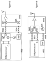
- a single cable may connect a number of antenna units in a daisy chain arrangement with each antenna unit connected to the next as shown in Figure 2 .
- this arrangement can be supported by a simple tap of baseband signal, or by signal regeneration.
- the uplink signal in such an embodiment will be provided by only a single antenna unit, with this arrangement supported by a switch in the antenna units between the receiving antenna unit and the central controller being configured to pass the signal from the desired uplink antenna unit.
- this topology is not unique to the baseband signal transmission method, and that the signals could be transmitted at IF, or indeed UHF.
- FIG. 9 shows a daisy chained low IF system comprising multiple independent baseband processors (901, 902) in the central controller 903, each carrying at a different IF frequency set by the local oscillators IF A and IF B.
- the remote antenna units (904, 905) contain filterbanks (906, 907) for the selection of one of the IF signals for UHF transmission. For clarity the uplink and local oscillator reference signals have been omitted.
- the downlink signal transmission over the cable may be carried out at a low intermediate frequency such that multiple signals can be multiplexed on to the twisted pair having a spectrum as shown in Figure 10 .
- the antenna unit selects the desired component by filtering, which can be by means of a switched filter bank (906,907) or a super heterodyne process, before up conversion to the desired RF frequency.
- the same method may be used to allow uplink signals from multiple antenna units to be carried over a single cable.
- each required uplink signal may use the same LO frequency where the RF frequency of each required uplink signal is different, or different LO frequencies may be used to support multiple uplink signals from antenna units sharing a common downlink frequency and potentially a common downlink modulation, where multiple uplinks signals are used for example to improve sensitivity or provide more advanced functions such as localisation.
- the antenna unit may be configured to change the properties of the transmitted signal, for example, the frequency, the phase and, if connected to a controllable antenna, the polarisation and beam shape or direction.
- the antenna unit may perform these changes in response to direct commands from the central controller, or the antenna unit may monitor the downlink baseband signals and perform changes in response to particular events in the downlink protocol.
- the antenna unit is configured to make a change to the phase of the transmitted signal, this may be performed by one or more of, a variable phase shifter after the quadrature modulator, by altering the phase of the local oscillator signal with respect to a reference signal, by altering the phase of the reference signal, by altering baseband IQ signals sent by the central controller, or by altering the phase of the IF signal sent by the central controller.
- a variable phase shifter after the quadrature modulator by altering the phase of the local oscillator signal with respect to a reference signal, by altering the phase of the reference signal, by altering baseband IQ signals sent by the central controller, or by altering the phase of the IF signal sent by the central controller.
- a single central controller may be connected to a large number of antenna units.
- the controller may select a sub-set of the connected antenna units to carry out an inventory.
- the reduced sub-set allowing a smaller interrogation field to be generated either for the purpose of reducing interference to surrounding areas or to achieve a higher resolution in the geographic location of the tags interrogated. Subsequent inventories may be carried out on other sub-sets of antenna units.
- the intermediate frequencies IF A and IF B may be chosen such that the desired UHF frequencies can be achieved using the same UHF local oscillator in antenna unit groups A and B, or they may be chosen subject to the requirement that different antenna unit groups should have different local oscillator frequencies. It can be desirable that RF A and RF B be different signals but occupy the same UHF frequency channel (allowing spatial frequency reuse).
- the uplink operates in a similar way in reverse.
- the same local oscillator in the antenna unit may be used to down convert the received signal to an intermediate frequency (such that the uplink IF is the same as the downlink IF) or different local oscillators may be used. Depending on the level of interference in other channels, filtering of the resulting IF may not be required.
- an analog buffer block in the central controller is employed to buffer the received baseband signals and provide noise filtering.
- the analog tag signals are fed into the R2000 chip for additional filtering and processing via the inputs designed for the external dense reader mode (DRM) filters, thus allowing bypassing of the RF to IF conversion stages on the IC.
- the reference source block allows future frequency and phase hopping of the local oscillator in the antenna subsystem by varying the phase and frequency of the reference signal. Thus, a 10 MHz signal is generated as an external reference source in this block for the frequency synthesizer in the antenna subsystem.
- Figure 12 shows an example of antenna subsystem which may be deployed in the RFID system and is mainly composed of quadrature modulator and demodulator, RF power amplifiers, and a PLL-based frequency synthesizer.
- the AD8349 quadrature modulator and the ADL5380 quadrature demodulator are used to fulfil up- and down-conversion tasks.
- the carrier frequency is generated by a fractional-N/integer-N PLL-based frequency synthesizer ADF4350, which can work with its internal oscillator with or without external reference signals, but in this implementation, an external 10MHz reference signal from the central controller is applied.
- Two RF amplifiers (RF5110G) are adopted for providing sufficient gain for the signals both in the downlink and uplink.
- the output power of this amplifier can be controlled from -10 dBm to +35 dBm by changing the voltage level of power control (Vapc).
- a RFID Tester TC-2600A was employed; this tester can emulate a reference tag for measuring reader performance.
- the RFID Tester can calculate the reader's bit error rate (BER) and frame error rate (FER) by comparing its sent RN16 signal while emulating a tag with the RN16 included in ACK signal from the reader. The sensitivity of the system can then be captured by determining the minimum backscattered power of remaining the desired BER or FER.
- BER bit error rate
- FER frame error rate
- a cost-effective UHF RFID system using low cost Cat5 Ethernet cable to address remote antennas has been described.
- the reader sensitivity of this system can achieve -94.5 dBm over 30m cable, and its sensitivity can still remain at around -94.2 dBm with 150m Cat5.
- the passive tags can be successfully detected over a 6 m wireless range following 300 m of twisted pair between the central controller and antenna.
Landscapes
- Engineering & Computer Science (AREA)
- Physics & Mathematics (AREA)
- Toxicology (AREA)
- Health & Medical Sciences (AREA)
- Theoretical Computer Science (AREA)
- Artificial Intelligence (AREA)
- Computer Vision & Pattern Recognition (AREA)
- General Physics & Mathematics (AREA)
- General Health & Medical Sciences (AREA)
- Electromagnetism (AREA)
- Computer Networks & Wireless Communication (AREA)
- Computer Security & Cryptography (AREA)
- Signal Processing (AREA)
- Mobile Radio Communication Systems (AREA)
- Near-Field Transmission Systems (AREA)
Claims (15)
- Système comprenant une pluralité de sous-systèmes d'antenne (101a, 101b, 105a, 602), chaque sous-système d'antenne comprenant une antenne (122) et un oscillateur (605), le système ayant pour objet la distribution de signaux RFID sur chacune des antennes, le système comprenant en outre :un module de commande central (601) pour générer des signaux et pour commander des opérations de protocole du système, dans lequel un dit sous-système d'antenne est configuré pour être à distance du module de commande central,le système étant caractérisé en ce qu'il comprend :un câble à paire(s) torsadée(s) (603) qui connecte le module de commande central à un sous-système d'antenne (602) de la pluralité de sous-systèmes d'antenne, le câble à paire(s) torsadée(s) transportant des représentations de bande de base d'une modulation lecteur à étiquette et d'une modulation étiquette à lecteur ; etun autre câble à paire(s) torsadée(s) (604) qui connecte le module de commande central audit sous-système d'antenne de la pluralité de sous-systèmes d'antenne, l'autre câble à paire(s) torsadée(s) transportant un signal de référence,dans lequel le système est configuré pour commander une différence de phase entre le signal de référence et un ou plusieurs des oscillateurs (605).
- Système selon la revendication 1, dans lequel un ou plusieurs de la pluralité de sous-systèmes d'antenne est configuré pour réaliser :une conversion élévatrice vers RF pour un signal de liaison descendante ; etune conversion abaisseuse depuis RF selon une bande de base pour un signal de liaison montante.
- Système comprenant une pluralité de sous-systèmes d'antenne (101a, 101b, 105a, 502), chaque sous-système d'antenne comprenant une antenne (122) et un oscillateur (505), le système ayant pour objet la distribution de signaux RFID sur chacune des antennes, le système comprenant en outre :un module de commande central (501) pour générer des signaux et pour commander des opérations de protocole du système, dans lequel un dit sous-système d'antenne est configuré pour être à distance du module de commande central,le système étant caractérisé en ce qu'il comprend :un câble à paire(s) torsadée(s) (503) qui connecte le module de commande central à un sous-système d'antenne (502) de la pluralité de sous-systèmes d'antenne, le câble à paire(s) torsadée(s) transportant des représentations de fréquence intermédiaire, IF, d'une modulation lecteur à étiquette et d'une modulation étiquette à lecteur ; etun autre câble à paire(s) torsadée(s) (504) qui connecte le module de commande central audit sous-système d'antenne de la pluralité de sous-systèmes d'antenne, l'autre câble à paire(s) torsadée(s) transportant un signal de référence,dans lequel le système est configuré pour commander une différence de phase entre le signal de référence et un ou plusieurs des oscillateurs.
- Système selon la revendication 1, 2 ou 3, où le système est configuré pour utiliser le signal de référence pour verrouiller en phase les oscillateurs.
- Système selon la revendication 1, 2, 3 ou 4, par lequel un ou plusieurs des sous-systèmes d'antenne de la pluralité de sous-systèmes d'antenne est alimenté en utilisant des signaux DC qui sont appliqués sur le câble à paire(s) torsadée(s).
- Système selon l'une quelconque des revendications précédentes, dans lequel le système est configuré pour utiliser le signal de référence pour maintenir une cohérence entre chacun des oscillateurs de la pluralité de sous-systèmes d'antenne.
- Système selon l'une quelconque des revendications précédentes dans lequel :
chaque sous-système d'antenne de la pluralité de sous-systèmes d'antenne est connecté au module de commande central via un câble à paire(s) torsadée(s) séparé (103a, 103b, 103c). - Système selon l'une quelconque des revendications 1 à 6, dans lequel chacun de la pluralité de sous-systèmes d'antenne est connecté en chaîne depuis le câble à paire(s) torsadée(s) (107a) qui connecte le module de commande central au sous-système d'antenne (105a).
- Système selon la revendication 8 lorsqu'elle dépend de la revendication 3, dans lequel chaque sous-système d'antenne comprend un filtre configurable, dans lequel lesdites représentations IF d'une modulation lecteur à étiquette et d'une modulation étiquette à lecteur comprennent des signaux IF différents de telle sorte que chaque sous-système d'antenne peut être configuré pour sélectionner une des représentations IF pour l'émission au moyen du filtre configurable du sous-système d'antenne.
- Système selon la revendication 9, dans lequel soit : un ou plusieurs des filtres configurables comprennent un banc de filtres commutés ; soit un ou plusieurs des filtres configurables est ou sont configurés pour mettre en oeuvre un processus superhétérodyne.
- Système selon la revendication 3, dans lequel chaque sous-système d'antenne utilise une fréquence IF différente pour permettre, au niveau du module de commande central, une séparation des représentations de la modulation étiquette à lecteur des sous-systèmes d'antenne.
- Système selon la revendication 2, dans lequel le système est configuré pour commander la pluralité de sous-systèmes d'antenne par l'intermédiaire d'une démodulation du signal de liaison descendante pour permettre une synchronisation de chaque sous-système d'antenne et d'un protocole de liaison descendante.
- Système selon l'une quelconque des revendications précédentes lorsqu'elle dépend de la revendication 9, dans lequel le système est configuré de telle sorte que la pluralité de sous-systèmes d'antenne sélectionnent simultanément une même fréquence IF pour former une cellule émettant un même signal sur une zone d'interrogation.
- Système selon la revendication 13, dans lequel le système est configuré pour modifier l'antenne d'au moins un des sous-systèmes d'antenne sur une fréquence IF particulière par rapport au temps pour changer une localisation physique de la cellule ou de la zone d'interrogation.
- Système selon l'une quelconque des revendications précédentes, configuré pour fournir une partie d'un signal arrivant sur une antenne d'émission à une voie de traitement de signal d'un signal en provenance d'une antenne de réception du système pour annuler une fuite de signal depuis le signal arrivant sur l'antenne d'émission, de préférence dans lequel le système comprend des sous-systèmes d'antenne séparés pour traiter le signal arrivant sur l'antenne d'émission et le signal en provenance de l'antenne de réception.
Applications Claiming Priority (2)
| Application Number | Priority Date | Filing Date | Title |
|---|---|---|---|
| GBGB1714992.3A GB201714992D0 (en) | 2017-09-18 | 2017-09-18 | RFID systems |
| PCT/GB2018/052661 WO2019053475A1 (fr) | 2017-09-18 | 2018-09-18 | Systèmes rfid |
Publications (2)
| Publication Number | Publication Date |
|---|---|
| EP3685302A1 EP3685302A1 (fr) | 2020-07-29 |
| EP3685302B1 true EP3685302B1 (fr) | 2023-12-27 |
Family
ID=60159483
Family Applications (1)
| Application Number | Title | Priority Date | Filing Date |
|---|---|---|---|
| EP18779746.9A Active EP3685302B1 (fr) | 2017-09-18 | 2018-09-18 | Systèmes rfid |
Country Status (4)
| Country | Link |
|---|---|
| US (1) | US10917134B2 (fr) |
| EP (1) | EP3685302B1 (fr) |
| GB (1) | GB201714992D0 (fr) |
| WO (1) | WO2019053475A1 (fr) |
Families Citing this family (9)
| Publication number | Priority date | Publication date | Assignee | Title |
|---|---|---|---|---|
| US11564188B2 (en) | 2017-10-17 | 2023-01-24 | Telefonaktiebolaget Lm Ericsson (Publ) | Distributed MIMO synchronization |
| US11616540B2 (en) | 2017-11-21 | 2023-03-28 | Telefonaktiebolaget Lm Ericsson (Publ) | Antenna arrangement for distributed massive MIMO |
| WO2021170379A1 (fr) * | 2020-02-25 | 2021-09-02 | Andrew Wireless Systems Gmbh | Décalage d'une bande de fréquence d'un signal d'interférence hors d'une bande passante d'un trajet de signal |
| EP4143980B1 (fr) | 2020-04-30 | 2025-12-10 | Telefonaktiebolaget LM ERICSSON (PUBL) | Interface améliorée dans des radios connectées en série |
| JP2022112832A (ja) * | 2021-01-22 | 2022-08-03 | 東芝テック株式会社 | 通信装置及び通信方法 |
| US12237858B2 (en) * | 2021-03-25 | 2025-02-25 | Skyworks Solutions, Inc. | Mobile devices with dual conversion of multiple frequency bands using a shared intermediate frequency |
| EP4187432B1 (fr) * | 2021-11-26 | 2025-08-13 | HID Textile Services SARL | Système de lecture d'étiquettes rfid |
| CA3217808A1 (fr) * | 2022-10-28 | 2024-04-28 | National Research Council Of Canada | Lecteur d'etiquette rfid integre |
| US20250190728A1 (en) * | 2023-12-11 | 2025-06-12 | T-Mobile Innovations Llc | Functionally-Split RFID Reader |
Family Cites Families (11)
| Publication number | Priority date | Publication date | Assignee | Title |
|---|---|---|---|---|
| WO1998045956A1 (fr) * | 1997-04-08 | 1998-10-15 | Lgc Wireless, Inc. | Systeme de distribution r.f. fournissant un service de circuit local sans fil fixe et une fonctionnalite d'antenne accrue |
| AU3718100A (en) | 1999-03-03 | 2000-09-21 | Pinpoint Corporation | Method and apparatus combining a tracking system and a wireless communication system |
| EP1949188B1 (fr) | 2005-10-28 | 2015-04-22 | Mojix, Inc. | Récepteur rfid |
| EP2044650B1 (fr) | 2006-07-11 | 2019-04-24 | Mojix, Inc. | Système rfid |
| WO2008118875A1 (fr) | 2007-03-23 | 2008-10-02 | Mojix, Inc. | Systèmes rfid utilisant un réseau d'exciteurs distribués |
| US10181060B2 (en) * | 2009-12-07 | 2019-01-15 | The Boeing Company | Methods and systems for real time RFID locating onboard an aircraft |
| GB201006907D0 (en) | 2010-04-26 | 2010-06-09 | Cambridge Entpr Ltd | RFID TAG interrogation systems |
| GB201006904D0 (en) | 2010-04-26 | 2010-06-09 | Cambridge Entpr Ltd | RFID TAG location systems |
| US10333584B2 (en) * | 2015-10-28 | 2019-06-25 | Politecnico Di Milano | Transporting radio signals using a low frequency band over copper cables |
| US10185849B2 (en) * | 2016-10-07 | 2019-01-22 | Intermec, Inc. | Systems and methods for controlling antennas |
| NL2019672B1 (en) * | 2017-10-05 | 2019-04-15 | N V Nederlandsche Apparatenfabriek Nedap | System of RFID reader units transmitting synchronized modulation using asynchronous carrier waves |
-
2017
- 2017-09-18 GB GBGB1714992.3A patent/GB201714992D0/en not_active Ceased
-
2018
- 2018-09-18 US US16/648,108 patent/US10917134B2/en active Active
- 2018-09-18 WO PCT/GB2018/052661 patent/WO2019053475A1/fr not_active Ceased
- 2018-09-18 EP EP18779746.9A patent/EP3685302B1/fr active Active
Also Published As
| Publication number | Publication date |
|---|---|
| GB201714992D0 (en) | 2017-11-01 |
| EP3685302A1 (fr) | 2020-07-29 |
| WO2019053475A1 (fr) | 2019-03-21 |
| US10917134B2 (en) | 2021-02-09 |
| US20200259520A1 (en) | 2020-08-13 |
Similar Documents
| Publication | Publication Date | Title |
|---|---|---|
| EP3685302B1 (fr) | Systèmes rfid | |
| EP2220792B1 (fr) | Système de communication radioélectrique en champ proche | |
| Forouzandeh et al. | Self-interference cancelation in frequency-domain chipless RFID readers | |
| US8838047B2 (en) | Dynamic RF front end | |
| US20040203478A1 (en) | Rfid receiver apparatus and method | |
| US7477917B2 (en) | RFID reader integrated with wireless communication device | |
| US7532908B2 (en) | Transceiver and method for combining RFID amplitude-modulated data with wireless phase-modulated data | |
| CN109039373B (zh) | 一种射频载波自干扰消除装置 | |
| CA2805752C (fr) | Architecture hybride pour une identification par radiofrequences et radiocommunication de paquets | |
| Ensworth et al. | Full-duplex bluetooth low energy (BLE) compatible backscatter communication system for mobile devices | |
| US7928832B2 (en) | Method for the operation of RFID read/write devices | |
| WO2015143731A1 (fr) | Lecteur mobile | |
| CN101159024A (zh) | 半导体集成电路装置以及接收装置 | |
| Fu et al. | Long distance passive UHF RFID system over ethernet cable | |
| Bae et al. | Analysis of phase noise requirements on local oscillator for RFID system considering range correlation | |
| US9727760B2 (en) | System and method for communication between RFID interrogators | |
| KR20100008282A (ko) | Rfid 리더 시스템 및 rfid 리더의 송신누설신호제거 방법 | |
| US8655261B2 (en) | RF redirection module and system incorporating the RF redirection module | |
| Boaventura et al. | Enhanced front-end to extend reading range of commercial RFID readers using efficient multisine signals | |
| Qi et al. | Low-power and compact frequency hopping RFID reader at 5.8 GHz for sensing applications in space | |
| KR101189400B1 (ko) | Rfid 리더 | |
| Fu et al. | A passive UHF RFID system over Ethernet cable for long range detection | |
| JP2008187227A (ja) | Rfidリーダ | |
| KR101114158B1 (ko) | Tdr 구조의 rfid 트랜시버 | |
| CN114389647B (zh) | 电子设备 |
Legal Events
| Date | Code | Title | Description |
|---|---|---|---|
| STAA | Information on the status of an ep patent application or granted ep patent |
Free format text: STATUS: UNKNOWN |
|
| STAA | Information on the status of an ep patent application or granted ep patent |
Free format text: STATUS: THE INTERNATIONAL PUBLICATION HAS BEEN MADE |
|
| PUAI | Public reference made under article 153(3) epc to a published international application that has entered the european phase |
Free format text: ORIGINAL CODE: 0009012 |
|
| STAA | Information on the status of an ep patent application or granted ep patent |
Free format text: STATUS: REQUEST FOR EXAMINATION WAS MADE |
|
| 17P | Request for examination filed |
Effective date: 20200318 |
|
| AK | Designated contracting states |
Kind code of ref document: A1 Designated state(s): AL AT BE BG CH CY CZ DE DK EE ES FI FR GB GR HR HU IE IS IT LI LT LU LV MC MK MT NL NO PL PT RO RS SE SI SK SM TR |
|
| AX | Request for extension of the european patent |
Extension state: BA ME |
|
| DAV | Request for validation of the european patent (deleted) | ||
| DAX | Request for extension of the european patent (deleted) | ||
| STAA | Information on the status of an ep patent application or granted ep patent |
Free format text: STATUS: EXAMINATION IS IN PROGRESS |
|
| 17Q | First examination report despatched |
Effective date: 20210519 |
|
| GRAP | Despatch of communication of intention to grant a patent |
Free format text: ORIGINAL CODE: EPIDOSNIGR1 |
|
| STAA | Information on the status of an ep patent application or granted ep patent |
Free format text: STATUS: GRANT OF PATENT IS INTENDED |
|
| INTG | Intention to grant announced |
Effective date: 20230711 |
|
| GRAS | Grant fee paid |
Free format text: ORIGINAL CODE: EPIDOSNIGR3 |
|
| GRAA | (expected) grant |
Free format text: ORIGINAL CODE: 0009210 |
|
| STAA | Information on the status of an ep patent application or granted ep patent |
Free format text: STATUS: THE PATENT HAS BEEN GRANTED |
|
| AK | Designated contracting states |
Kind code of ref document: B1 Designated state(s): AL AT BE BG CH CY CZ DE DK EE ES FI FR GB GR HR HU IE IS IT LI LT LU LV MC MK MT NL NO PL PT RO RS SE SI SK SM TR |
|
| REG | Reference to a national code |
Ref country code: GB Ref legal event code: FG4D |
|
| REG | Reference to a national code |
Ref country code: CH Ref legal event code: EP |
|
| REG | Reference to a national code |
Ref country code: DE Ref legal event code: R096 Ref document number: 602018063261 Country of ref document: DE |
|
| REG | Reference to a national code |
Ref country code: IE Ref legal event code: FG4D |
|
| REG | Reference to a national code |
Ref country code: NL Ref legal event code: FP |
|
| PG25 | Lapsed in a contracting state [announced via postgrant information from national office to epo] |
Ref country code: GR Free format text: LAPSE BECAUSE OF FAILURE TO SUBMIT A TRANSLATION OF THE DESCRIPTION OR TO PAY THE FEE WITHIN THE PRESCRIBED TIME-LIMIT Effective date: 20240328 |
|
| REG | Reference to a national code |
Ref country code: LT Ref legal event code: MG9D |
|
| PG25 | Lapsed in a contracting state [announced via postgrant information from national office to epo] |
Ref country code: LT Free format text: LAPSE BECAUSE OF FAILURE TO SUBMIT A TRANSLATION OF THE DESCRIPTION OR TO PAY THE FEE WITHIN THE PRESCRIBED TIME-LIMIT Effective date: 20231227 |
|
| PG25 | Lapsed in a contracting state [announced via postgrant information from national office to epo] |
Ref country code: ES Free format text: LAPSE BECAUSE OF FAILURE TO SUBMIT A TRANSLATION OF THE DESCRIPTION OR TO PAY THE FEE WITHIN THE PRESCRIBED TIME-LIMIT Effective date: 20231227 |
|
| PG25 | Lapsed in a contracting state [announced via postgrant information from national office to epo] |
Ref country code: LT Free format text: LAPSE BECAUSE OF FAILURE TO SUBMIT A TRANSLATION OF THE DESCRIPTION OR TO PAY THE FEE WITHIN THE PRESCRIBED TIME-LIMIT Effective date: 20231227 Ref country code: GR Free format text: LAPSE BECAUSE OF FAILURE TO SUBMIT A TRANSLATION OF THE DESCRIPTION OR TO PAY THE FEE WITHIN THE PRESCRIBED TIME-LIMIT Effective date: 20240328 Ref country code: FI Free format text: LAPSE BECAUSE OF FAILURE TO SUBMIT A TRANSLATION OF THE DESCRIPTION OR TO PAY THE FEE WITHIN THE PRESCRIBED TIME-LIMIT Effective date: 20231227 Ref country code: ES Free format text: LAPSE BECAUSE OF FAILURE TO SUBMIT A TRANSLATION OF THE DESCRIPTION OR TO PAY THE FEE WITHIN THE PRESCRIBED TIME-LIMIT Effective date: 20231227 Ref country code: BG Free format text: LAPSE BECAUSE OF FAILURE TO SUBMIT A TRANSLATION OF THE DESCRIPTION OR TO PAY THE FEE WITHIN THE PRESCRIBED TIME-LIMIT Effective date: 20240327 |
|
| REG | Reference to a national code |
Ref country code: AT Ref legal event code: MK05 Ref document number: 1645210 Country of ref document: AT Kind code of ref document: T Effective date: 20231227 |
|
| PG25 | Lapsed in a contracting state [announced via postgrant information from national office to epo] |
Ref country code: SE Free format text: LAPSE BECAUSE OF FAILURE TO SUBMIT A TRANSLATION OF THE DESCRIPTION OR TO PAY THE FEE WITHIN THE PRESCRIBED TIME-LIMIT Effective date: 20231227 Ref country code: RS Free format text: LAPSE BECAUSE OF FAILURE TO SUBMIT A TRANSLATION OF THE DESCRIPTION OR TO PAY THE FEE WITHIN THE PRESCRIBED TIME-LIMIT Effective date: 20231227 Ref country code: NO Free format text: LAPSE BECAUSE OF FAILURE TO SUBMIT A TRANSLATION OF THE DESCRIPTION OR TO PAY THE FEE WITHIN THE PRESCRIBED TIME-LIMIT Effective date: 20240327 Ref country code: LV Free format text: LAPSE BECAUSE OF FAILURE TO SUBMIT A TRANSLATION OF THE DESCRIPTION OR TO PAY THE FEE WITHIN THE PRESCRIBED TIME-LIMIT Effective date: 20231227 Ref country code: HR Free format text: LAPSE BECAUSE OF FAILURE TO SUBMIT A TRANSLATION OF THE DESCRIPTION OR TO PAY THE FEE WITHIN THE PRESCRIBED TIME-LIMIT Effective date: 20231227 |
|
| PG25 | Lapsed in a contracting state [announced via postgrant information from national office to epo] |
Ref country code: IS Free format text: LAPSE BECAUSE OF FAILURE TO SUBMIT A TRANSLATION OF THE DESCRIPTION OR TO PAY THE FEE WITHIN THE PRESCRIBED TIME-LIMIT Effective date: 20240427 |
|
| PG25 | Lapsed in a contracting state [announced via postgrant information from national office to epo] |
Ref country code: AT Free format text: LAPSE BECAUSE OF FAILURE TO SUBMIT A TRANSLATION OF THE DESCRIPTION OR TO PAY THE FEE WITHIN THE PRESCRIBED TIME-LIMIT Effective date: 20231227 Ref country code: CZ Free format text: LAPSE BECAUSE OF FAILURE TO SUBMIT A TRANSLATION OF THE DESCRIPTION OR TO PAY THE FEE WITHIN THE PRESCRIBED TIME-LIMIT Effective date: 20231227 |
|
| PG25 | Lapsed in a contracting state [announced via postgrant information from national office to epo] |
Ref country code: SK Free format text: LAPSE BECAUSE OF FAILURE TO SUBMIT A TRANSLATION OF THE DESCRIPTION OR TO PAY THE FEE WITHIN THE PRESCRIBED TIME-LIMIT Effective date: 20231227 |
|
| PG25 | Lapsed in a contracting state [announced via postgrant information from national office to epo] |
Ref country code: SM Free format text: LAPSE BECAUSE OF FAILURE TO SUBMIT A TRANSLATION OF THE DESCRIPTION OR TO PAY THE FEE WITHIN THE PRESCRIBED TIME-LIMIT Effective date: 20231227 Ref country code: SK Free format text: LAPSE BECAUSE OF FAILURE TO SUBMIT A TRANSLATION OF THE DESCRIPTION OR TO PAY THE FEE WITHIN THE PRESCRIBED TIME-LIMIT Effective date: 20231227 Ref country code: RO Free format text: LAPSE BECAUSE OF FAILURE TO SUBMIT A TRANSLATION OF THE DESCRIPTION OR TO PAY THE FEE WITHIN THE PRESCRIBED TIME-LIMIT Effective date: 20231227 Ref country code: IT Free format text: LAPSE BECAUSE OF FAILURE TO SUBMIT A TRANSLATION OF THE DESCRIPTION OR TO PAY THE FEE WITHIN THE PRESCRIBED TIME-LIMIT Effective date: 20231227 Ref country code: IS Free format text: LAPSE BECAUSE OF FAILURE TO SUBMIT A TRANSLATION OF THE DESCRIPTION OR TO PAY THE FEE WITHIN THE PRESCRIBED TIME-LIMIT Effective date: 20240427 Ref country code: EE Free format text: LAPSE BECAUSE OF FAILURE TO SUBMIT A TRANSLATION OF THE DESCRIPTION OR TO PAY THE FEE WITHIN THE PRESCRIBED TIME-LIMIT Effective date: 20231227 Ref country code: CZ Free format text: LAPSE BECAUSE OF FAILURE TO SUBMIT A TRANSLATION OF THE DESCRIPTION OR TO PAY THE FEE WITHIN THE PRESCRIBED TIME-LIMIT Effective date: 20231227 Ref country code: AT Free format text: LAPSE BECAUSE OF FAILURE TO SUBMIT A TRANSLATION OF THE DESCRIPTION OR TO PAY THE FEE WITHIN THE PRESCRIBED TIME-LIMIT Effective date: 20231227 |
|
| PG25 | Lapsed in a contracting state [announced via postgrant information from national office to epo] |
Ref country code: PL Free format text: LAPSE BECAUSE OF FAILURE TO SUBMIT A TRANSLATION OF THE DESCRIPTION OR TO PAY THE FEE WITHIN THE PRESCRIBED TIME-LIMIT Effective date: 20231227 Ref country code: PT Free format text: LAPSE BECAUSE OF FAILURE TO SUBMIT A TRANSLATION OF THE DESCRIPTION OR TO PAY THE FEE WITHIN THE PRESCRIBED TIME-LIMIT Effective date: 20240429 |
|
| PG25 | Lapsed in a contracting state [announced via postgrant information from national office to epo] |
Ref country code: PT Free format text: LAPSE BECAUSE OF FAILURE TO SUBMIT A TRANSLATION OF THE DESCRIPTION OR TO PAY THE FEE WITHIN THE PRESCRIBED TIME-LIMIT Effective date: 20240429 Ref country code: PL Free format text: LAPSE BECAUSE OF FAILURE TO SUBMIT A TRANSLATION OF THE DESCRIPTION OR TO PAY THE FEE WITHIN THE PRESCRIBED TIME-LIMIT Effective date: 20231227 |
|
| REG | Reference to a national code |
Ref country code: DE Ref legal event code: R097 Ref document number: 602018063261 Country of ref document: DE |
|
| PG25 | Lapsed in a contracting state [announced via postgrant information from national office to epo] |
Ref country code: DK Free format text: LAPSE BECAUSE OF FAILURE TO SUBMIT A TRANSLATION OF THE DESCRIPTION OR TO PAY THE FEE WITHIN THE PRESCRIBED TIME-LIMIT Effective date: 20231227 |
|
| PG25 | Lapsed in a contracting state [announced via postgrant information from national office to epo] |
Ref country code: DK Free format text: LAPSE BECAUSE OF FAILURE TO SUBMIT A TRANSLATION OF THE DESCRIPTION OR TO PAY THE FEE WITHIN THE PRESCRIBED TIME-LIMIT Effective date: 20231227 |
|
| PLBE | No opposition filed within time limit |
Free format text: ORIGINAL CODE: 0009261 |
|
| STAA | Information on the status of an ep patent application or granted ep patent |
Free format text: STATUS: NO OPPOSITION FILED WITHIN TIME LIMIT |
|
| 26N | No opposition filed |
Effective date: 20240930 |
|
| PG25 | Lapsed in a contracting state [announced via postgrant information from national office to epo] |
Ref country code: MC Free format text: LAPSE BECAUSE OF FAILURE TO SUBMIT A TRANSLATION OF THE DESCRIPTION OR TO PAY THE FEE WITHIN THE PRESCRIBED TIME-LIMIT Effective date: 20231227 Ref country code: SI Free format text: LAPSE BECAUSE OF FAILURE TO SUBMIT A TRANSLATION OF THE DESCRIPTION OR TO PAY THE FEE WITHIN THE PRESCRIBED TIME-LIMIT Effective date: 20231227 |
|
| REG | Reference to a national code |
Ref country code: CH Ref legal event code: PL |
|
| PG25 | Lapsed in a contracting state [announced via postgrant information from national office to epo] |
Ref country code: LU Free format text: LAPSE BECAUSE OF NON-PAYMENT OF DUE FEES Effective date: 20240918 |
|
| REG | Reference to a national code |
Ref country code: BE Ref legal event code: MM Effective date: 20240930 |
|
| PG25 | Lapsed in a contracting state [announced via postgrant information from national office to epo] |
Ref country code: BE Free format text: LAPSE BECAUSE OF NON-PAYMENT OF DUE FEES Effective date: 20240930 |
|
| PG25 | Lapsed in a contracting state [announced via postgrant information from national office to epo] |
Ref country code: CH Free format text: LAPSE BECAUSE OF NON-PAYMENT OF DUE FEES Effective date: 20240930 |
|
| PG25 | Lapsed in a contracting state [announced via postgrant information from national office to epo] |
Ref country code: IE Free format text: LAPSE BECAUSE OF NON-PAYMENT OF DUE FEES Effective date: 20240918 |
|
| PGFP | Annual fee paid to national office [announced via postgrant information from national office to epo] |
Ref country code: DE Payment date: 20250919 Year of fee payment: 8 |
|
| PGFP | Annual fee paid to national office [announced via postgrant information from national office to epo] |
Ref country code: NL Payment date: 20250922 Year of fee payment: 8 |
|
| PGFP | Annual fee paid to national office [announced via postgrant information from national office to epo] |
Ref country code: GB Payment date: 20250820 Year of fee payment: 8 |
|
| PGFP | Annual fee paid to national office [announced via postgrant information from national office to epo] |
Ref country code: FR Payment date: 20250925 Year of fee payment: 8 |
|
| PG25 | Lapsed in a contracting state [announced via postgrant information from national office to epo] |
Ref country code: CY Free format text: LAPSE BECAUSE OF FAILURE TO SUBMIT A TRANSLATION OF THE DESCRIPTION OR TO PAY THE FEE WITHIN THE PRESCRIBED TIME-LIMIT; INVALID AB INITIO Effective date: 20180918 |
|
| PG25 | Lapsed in a contracting state [announced via postgrant information from national office to epo] |
Ref country code: HU Free format text: LAPSE BECAUSE OF FAILURE TO SUBMIT A TRANSLATION OF THE DESCRIPTION OR TO PAY THE FEE WITHIN THE PRESCRIBED TIME-LIMIT; INVALID AB INITIO Effective date: 20180918 |