EP3685347B1 - Élimination d'artéfacts d'images de tissus - Google Patents
Élimination d'artéfacts d'images de tissus Download PDFInfo
- Publication number
- EP3685347B1 EP3685347B1 EP18769411.2A EP18769411A EP3685347B1 EP 3685347 B1 EP3685347 B1 EP 3685347B1 EP 18769411 A EP18769411 A EP 18769411A EP 3685347 B1 EP3685347 B1 EP 3685347B1
- Authority
- EP
- European Patent Office
- Prior art keywords
- image
- artifact
- logic
- generation
- artifacts
- Prior art date
- Legal status (The legal status is an assumption and is not a legal conclusion. Google has not performed a legal analysis and makes no representation as to the accuracy of the status listed.)
- Active
Links
Images


Classifications
-
- G—PHYSICS
- G06—COMPUTING OR CALCULATING; COUNTING
- G06T—IMAGE DATA PROCESSING OR GENERATION, IN GENERAL
- G06T5/00—Image enhancement or restoration
- G06T5/77—Retouching; Inpainting; Scratch removal
-
- G—PHYSICS
- G06—COMPUTING OR CALCULATING; COUNTING
- G06T—IMAGE DATA PROCESSING OR GENERATION, IN GENERAL
- G06T5/00—Image enhancement or restoration
- G06T5/60—Image enhancement or restoration using machine learning, e.g. neural networks
-
- G—PHYSICS
- G06—COMPUTING OR CALCULATING; COUNTING
- G06N—COMPUTING ARRANGEMENTS BASED ON SPECIFIC COMPUTATIONAL MODELS
- G06N20/00—Machine learning
-
- G—PHYSICS
- G06—COMPUTING OR CALCULATING; COUNTING
- G06N—COMPUTING ARRANGEMENTS BASED ON SPECIFIC COMPUTATIONAL MODELS
- G06N3/00—Computing arrangements based on biological models
- G06N3/02—Neural networks
- G06N3/04—Architecture, e.g. interconnection topology
-
- G—PHYSICS
- G06—COMPUTING OR CALCULATING; COUNTING
- G06N—COMPUTING ARRANGEMENTS BASED ON SPECIFIC COMPUTATIONAL MODELS
- G06N3/00—Computing arrangements based on biological models
- G06N3/02—Neural networks
- G06N3/04—Architecture, e.g. interconnection topology
- G06N3/045—Combinations of networks
- G06N3/0455—Auto-encoder networks; Encoder-decoder networks
-
- G—PHYSICS
- G06—COMPUTING OR CALCULATING; COUNTING
- G06N—COMPUTING ARRANGEMENTS BASED ON SPECIFIC COMPUTATIONAL MODELS
- G06N3/00—Computing arrangements based on biological models
- G06N3/02—Neural networks
- G06N3/04—Architecture, e.g. interconnection topology
- G06N3/0464—Convolutional networks [CNN, ConvNet]
-
- G—PHYSICS
- G06—COMPUTING OR CALCULATING; COUNTING
- G06N—COMPUTING ARRANGEMENTS BASED ON SPECIFIC COMPUTATIONAL MODELS
- G06N3/00—Computing arrangements based on biological models
- G06N3/02—Neural networks
- G06N3/08—Learning methods
- G06N3/09—Supervised learning
-
- G—PHYSICS
- G16—INFORMATION AND COMMUNICATION TECHNOLOGY [ICT] SPECIALLY ADAPTED FOR SPECIFIC APPLICATION FIELDS
- G16H—HEALTHCARE INFORMATICS, i.e. INFORMATION AND COMMUNICATION TECHNOLOGY [ICT] SPECIALLY ADAPTED FOR THE HANDLING OR PROCESSING OF MEDICAL OR HEALTHCARE DATA
- G16H30/00—ICT specially adapted for the handling or processing of medical images
- G16H30/40—ICT specially adapted for the handling or processing of medical images for processing medical images, e.g. editing
-
- G—PHYSICS
- G06—COMPUTING OR CALCULATING; COUNTING
- G06T—IMAGE DATA PROCESSING OR GENERATION, IN GENERAL
- G06T2207/00—Indexing scheme for image analysis or image enhancement
- G06T2207/10—Image acquisition modality
- G06T2207/10024—Color image
-
- G—PHYSICS
- G06—COMPUTING OR CALCULATING; COUNTING
- G06T—IMAGE DATA PROCESSING OR GENERATION, IN GENERAL
- G06T2207/00—Indexing scheme for image analysis or image enhancement
- G06T2207/10—Image acquisition modality
- G06T2207/10056—Microscopic image
-
- G—PHYSICS
- G06—COMPUTING OR CALCULATING; COUNTING
- G06T—IMAGE DATA PROCESSING OR GENERATION, IN GENERAL
- G06T2207/00—Indexing scheme for image analysis or image enhancement
- G06T2207/20—Special algorithmic details
- G06T2207/20081—Training; Learning
-
- G—PHYSICS
- G06—COMPUTING OR CALCULATING; COUNTING
- G06T—IMAGE DATA PROCESSING OR GENERATION, IN GENERAL
- G06T2207/00—Indexing scheme for image analysis or image enhancement
- G06T2207/20—Special algorithmic details
- G06T2207/20084—Artificial neural networks [ANN]
-
- G—PHYSICS
- G06—COMPUTING OR CALCULATING; COUNTING
- G06T—IMAGE DATA PROCESSING OR GENERATION, IN GENERAL
- G06T2207/00—Indexing scheme for image analysis or image enhancement
- G06T2207/30—Subject of image; Context of image processing
- G06T2207/30004—Biomedical image processing
- G06T2207/30024—Cell structures in vitro; Tissue sections in vitro
Definitions
- the invention relates to image analysis, and more particularly to the removal of artifacts from tissue images.
- digital pathology information encoded in a digital image of a tissue slide is extracted from the image for answering various biomedical questions, e.g. for assisting a health care professional in the diagnosis and treatment of diseases.
- the field of digital pathology is currently regarded as one of the most promising avenues of diagnostic medicine in order to achieve even better, faster and cheaper diagnosis, prognosis and prediction of cancer and other important diseases.
- Digital pathology techniques are also widely used in the context of drug development for assisting pathologists in understanding the tumor microenvironment, learning about patient response, drug mode of actions and other information available from the tissue images.
- the scanned digital tissue images tend to have several types of noise related to both staining process and scanning process. These noise artifacts present a problem to both manual and automatic analysis.
- the artifacts can substantially affect and limit both automatic algorithm results and manual scoring by expert pathologists or at least make such manual or automatic scoring very difficult and inconsistent.
- US 2017/0213321 A1 describes a computer-implemented method for denoising image data.
- the method includes a computer system receiving an input image comprising noisy image data and denoising the input image using a deep multi-scale network comprising a plurality of multi-scale networks sequentially collected.
- Each respective multi-scale network performs a denoising process which includes dividing the input image into a plurality of image patches and denoising those image patches over multiple levels of decomposition using a threshold-based denoising process.
- the threshold-based denoising process denoises each respective image patch using a threshold which is scaled according to an estimation of noise present in the respective image patch.
- the noising process further comprises the assembly of a denoised image by averaging over the image patches.
- Gao and Grauman (“On-demand Learning of Deep Image Restoration", 2017 IEEE International Conference on Computer Vision, ICCV, August 2017 ) describes an examination of the weakness of conventional "fixated” models and demonstrates that training general models to handle arbitrary levels of corruption is non-trivial.
- an on-demand learning algorithm for training image restoration models with deep convolutional neural networks is described. The main idea is to exploit a feedback mechanism to self-generate training instances where they are needed most, thereby learning models that can generalize across difficulty levels.
- a problem associated with the current denoising approaches is that the generation of the noise-removal logic involves a training phase of a machine learning logic on training data that is hard to obtain in the required quantity and quality: typically, images have to be annotated manually for generating a training data set in which noise artifacts and/or tissue structures which look similar to artifacts but which should not be identified as noise artifacts are labeled as "true artifacts" or "true tissue structures”.
- This process is highly time consuming and requires many hours, days or even weeks of work of one or more experienced pathologists.
- manual annotation of "real noise” and "real tissue” may be subjective and different pathologists may have different opinions regarding the nature of a particular image section that cannot surely be classified as artifact.
- the creation of artifact removal program logic currently requires the creation of training data sets which is very time consuming and therefore expensive.
- the training data sets used in praxis are often hardly of sufficient size to allow for the generation of a noise removal program logic of sufficient accuracy, because the training of program logic that is able to accurately remove image artifacts typically requires a large training dataset that covers many different manifestations of a particular artifact type.
- Embodiments of the invention are given in the dependent claims. Embodiments of the present invention can be freely combined with each other if they are not mutually exclusive.
- the invention relates to a digital pathology method according to appended claim 1.
- Other aspects comprise a computer program and a system according, respectively, to appended claims 16 and 17.
- the method comprises:
- the artifact generation logic can in particular be an image-capture-device specific artifact-generation logic ("option A”) or a staining protocol related artifact ("option B").
- Said features may be advantageous, because the training dataset comprising "true artifact-free" and "true artifact-containing" images can be created fully automatically.
- a very large training dataset can be generated.
- high quality images which are basically free of any artifacts or at least free of artifacts of a particular type can be obtained comparatively easy.
- artifacts resulting from dust in the optical system of a camera can be avoided simply by using a microscope whose optical system is basically free of dust grains. This microscope can be used for capturing hundreds and thousands of images of different tissues stained with different stains according to different staining protocols.
- a large number of "true noise-free training images” can be captured easily, and a corresponding number of "true noise-containing training images” can be created from the former automatically by applying the image-artifact-generation logic.
- the generated training data set may be larger than a manually annotated training data set, because high-quality, noise free images can typically obtained easily.
- the accuracy of the trained machine learning logic may be higher.
- inconsistencies in the annotations in the training data set inherent to the manual annotation process may be avoided, because the artifacts in the training images are created automatically and the artifact generation algorithm "knows" at which region in an image an artifact was created.
- the plurality of original images comprises images depicting tissues derived from many different tissue types and/or depicting tissues having been stained with many different stains and/or depicting tissues having been stained according to many different staining protocols and/or depicting tissues whose image was captured by many different image capturing systems and/or depicting tissues in many different resolutions.
- the automated generation of the degraded version of an image is performed by a "image degradation" application used for generating a training data set that is separate from the program logic used for artifacts removal.
- the automated generation of the degraded version of an original image is performed by the machine learning algorithm that is trained to "learn" to remove the artifact.
- a machine learning logic can be used for "learning" one or more artifacts removal logics, whereby only the original images are input into said machine learning logic during the training as well as during the test phase.
- the machine learning logic is configured to operate in two different modes, the training phase mode and the test phase mode. Selectively in the training phase mode, this machine learning logic will automatically generate the degraded image versions from the original images received as input. In the test phase mode, the trained machine learning logic will merely remove the artifacts from the original images received as input.
- the two different functionalities may be implemented in different modules of the machine learning algorithm.
- the automated generation of the degraded image version can be performed by a particular layer of a neural network, whereby one or more other layers of said network are used and trained to remove said artifact from an image.
- tissue images which are basically free of noise artifacts from many different tissues and/or from many different image capturing devices and/or from tissue sections subjected to many different conditions and then automatically deriving a "degraded", noisy version of said image can typically performed much faster and easier than annotating a training data set having the same broad coverage manually.
- a machine learning algorithm trained to remove artifacts from the above described automatically generated data set may be more accurate and more robust against variations regarding the tissue type, the stain, the staining protocol and the like because of the increased size and diversity of the training data set.
- the training of the untrained version of the first machine-learning logic comprises inputting the original images and their respectively generated first degraded images into the untrained version of the first machine-learning-logic.
- Each of the first degraded images is annotated as artifact-afflicted version of a respective one of the original images.
- the first machine learning logic encodes a first artifacts-removal logic.
- the training is performed by applying the first artifacts-removal logic on the first degraded images for generating a first reconstructed image from each of the first degraded images and by automatically modifying the first artifacts-removal logic such that deviations of the first reconstructed images from the original images from which the first reconstructed images were derived are minimized.
- Supervised machine learning techniques may be implemented in various forms, e.g. as a neural network based machine learning logic, as support vector machine based machine learning logic, or the like.
- the method further comprises generating, for each of the original images, a second artificially degraded image.
- the second artificially degraded image is generated by applying a second image-artifact-generation logic on each of the original images.
- the second image-artifact-generation logic is configured for specifically generating a second type of artifact.
- the generation of the program logic further comprises: training an untrained version of a second machine-learning logic that encodes a second artifacts-removal logic on the original images and their respectively generated second degraded images; and combining the trained first machine-learning logic with the trained second machine-learning logic for providing the program logic; the generated program logic is configured for removing artifacts of at least the first and the second artifact type.
- the first and second machine-learning logics can be part of the same machine learning architecture that is trained in a single training step on a training data set comprising both the first and second degraded images.
- Training one or more machine learning logics on two separate sets of artificially degraded images may be advantageous in case an artifact removal logic shall be generated which is capable of selectively removing artifacts of a particular type from an image.
- the generated artifacts removal logic may be integrated in an image analysis software package that is sold together with or for use in combination with a particular microscope.
- the software may allow the user of the software to select one or more artifacts types, e.g. "blur artifacts", “focus artifacts”, “dust”, etc. for selectively removing artifacts of a particular type from an image.
- the software may allow the user to selectively select and use e.g. the first artifacts-removal logic or to selectively select and use the second artifacts-removal logic.
- the artifacts removal logic is applied in real time during image acquisition, e.g. during an image scanning process.
- a "clean" version is generated by applying one or more artifacts removal algorithms on the currently acquired image.
- one or more artifacts removal logics are applied on already acquired images, e.g. on images having been acquired in the past and having been stored in the form of an image library on a storage medium.
- combining the trained first machine-learning logic with the trained second machine-learning logic for providing the program logic may comprise combining two separately addressable and separately callable trained program logics into the same software application program.
- the combination may be an integral part of the training process.
- a single machine learning software may be trained on a data set comprising the original images and a mixture of the first and the second degraded images.
- the degraded image generated by one artifacts-generation-logic is input to at least one further artifacts generation logic of a different type to generate a two-fold (or, if further artifact-generation-logics are applied, a multi-fold) degraded image.
- This may allow the generation and training of an artifacts-removal-logic adapted to remove artifacts of many different types from an image in a step-wise manner.
- the returned artifacts-removal logic can be configured such that it at first removes bad-focus noise such as blur and then removes line noise and speckle noise caused by physical obstructions such as hair, dust, etc.
- the artifacts-removal logic can remove staining artifacts such as non specific staining.
- the first artificially degraded images could comprise artifacts which simulate blurring artifacts and the second artificially degraded images could comprise artifacts which simulate a non-specific staining artifact.
- Optical noise such as blur does typically not depend on types of noise such as the presence of undesired physical objects (e.g. hair, dust) in the image.
- the undesired physical objects may cause an autofocus mechanism to select the wrong focus layer.
- the speckle noise may be affected by the bad-focus noise in case the bad-focus noise results in a blurring of the tissue section as well as of the speckles.
- the second machine learning logic is trained by inputting the original images and their respectively generated second degraded images into an untrained version of the second machine-learning-logic, whereby each of the second degraded images is annotated as artifact-afflicted version of a respective one of the original images.
- the second machine learning logic encodes a second artifacts-removal logic.
- the training is performed by applying the second artifacts-removal logic on the second degraded images for generating a second reconstructed image from each of the second degraded images and by automatically modifying the second artifacts-removal logic such that deviations of said second reconstructed images from the original images from which said second reconstructed images were derived are minimized.
- the second machine-learning logic and/or any -machine learning logic encoding a multi-step-artifacts-removal logic described further below may be trained such that an error function being descriptive of a deviation of the original image and the result of applying an image reconstruction logic on a degraded image is minimized.
- the second machine learning algorithm comprises a sub-module that automatically generates the artifact-afflicted version of the original images as described for embodiments above or is a sub-module of a machine learning logic that comprises a further sub-module configured to automatically generate the artifact-afflicted version of the original images.
- the expression "inputting a degraded (artifact afflicted) version of an original image” also includes the option that the degraded version is generated by a software logic that is bundled with the second program logic into a single executable program logic.
- the first, the second and any further machine-learning logic for removing artifacts of one or more artifact types is implemented in the same machine learning logic, e.g. in the same instance of a neural network.
- neural networks can be used as the machine learning logic to be trained.
- the number of networks that are employed for training the respective artifacts generation logics and artifacts removal logics can be determined by trial and error. If a network architecture comprising a single neural network does not perform well, the network architecture may be extended to two networks or three networks or a different network layer architecture. Alternatively, multiple different network architectures are trained in parallel and the results generated by the trained networks on test images are combined and aggregated to generate a consolidated result of multiple networks that has a higher accuracy than the results obtained from any of them separately ("ensemble method” or "ensemble learning”).
- the method comprises providing a GUI to a user, the GUI enabling the user to select one or more of a set of predefined artifacts types and a corresponding set of selected artifacts removal logics to be applied automatically on any original image to be processed.
- the program logic configured for removing artifacts that is to be generated is a program logic configured for removing at least a number N different artifacts types from the digital tissue images.
- the number N is an integer larger than 1.
- the method further comprises: providing, for each of the N different artifacts types, a respective artifact-generation logic configured for specifically generating said particular type of artifact; applying, according to a first sequence, the number N different image-artifact-generation logics on the original images; thereby, the first image-artifact-generation logic within the first sequence takes each of the original images as input and outputs a degraded version of said image; the degraded image output by the first and any subsequent image-artifact-generation logic is used as input image by the next one of the N different image-artifact-generation logics in the first sequence; thereby, for each of the original images, a first multi-fold degraded image is generated.
- the generation of the program logic further comprises training a machine-learning logic that encodes a multi-step-artifacts-removal logic on at least the original images and their respectively generated first multi-fold degraded images; and using said trained multi-step-artifacts-removal logic for providing the program logic or for providing a part of the program logic that is to be generated.
- the machine-learning logic that encodes a multi-step-artifacts-removal logic is an untrained machine learning logic that uses the output generated from a plurality of other machine learning logics for learning to correctly remove multiple different types of image artifacts.
- the other machine learning logics have respectively been trained to remove a particular type of image artifact.
- the trained multi-step-artifacts-removal logic is combined with the trained first machine-learning logic for providing the program logic.
- the resulting program logic is configured for sequentially removing artifacts of each of the N types of artifacts. The removal is preferably performed in accordance with the reverse order of the first sequence.
- the training of the machine-learning logic for providing the trained multi-step-artifacts-removal logic is performed such that the multi-step-artifacts-removal logic reconstructs the original image from the multifold-degraded training images.
- the multi-step-artifacts-removal logic may be configured to call any of the first or second ("single-artifact")-machine-learning logics in different orders and may be configured to learn a sequence of artifact removal operations that is best suited to reconstruct an image that is very similar or identical to the original image.
- the number N may be "3" and the first sequence may comprise the following types of artifacts in the following order: a) “overstaining", b) “dust artifacts” and c) "blurring artifacts”.
- an image may comprise artifacts of many different types, whereby an artifact may be overlaid by, distorted or otherwise affected by a later introduced type of artifact.
- the artifacts removal logic may be trained such that it is capable of identifying and compensating also a sequence of image artifacts of different types and thus may be able to compensate also complex combinations of artifacts of different types commonly observed in praxis in digital pathology.
- the intermediate images created in each degradation step defined by a sequence of artifact-generation logics are respectively used as "auxiliary loss" in the network.
- auxiliary loss This means that during training not only the last output of the net is compared to the clean image, but in one or more places along the processing layers an additional output image (“intermediate image") is created by the network (during training only) and compared to the original image to create a loss that drives the training of the preceding layers.
- a first auxiliary loss image (a first intermediate image) of the partially degraded image e.g.
- the method further comprises applying, according to at least a second sequence, the number N different image-artifact-generation logics on the original images.
- the first image-artifact-generation logic within said second sequence takes each of the original images as input.
- the degraded image output by the first and any subsequent image-artifact-generation logic is used as input image by the next one of the different image-artifact-generation logics in the second sequence.
- a first multi-fold-degraded image is obtained by sequentially applying the image-artifact-generation logics according to the first sequence as described above.
- one second multi-fold-degraded image is obtained per original image by sequentially applying the image-artifact-generation logics according to the second sequence as described above.
- the first and second multi-fold-degraded image may differ from each other, because the sequence of applying the image degradation algorithm typically has an impact on the resulting image. For example, a depicted grain of dust may have sharp edges if the dust artifact is added after a blurring artifact was added to an image and may have blurred edges if the blurring artifact was added after the dust artifact.
- the training of the machine-learning logic that encodes a multi-step-artifacts-removal logic is performed on at least the original images and their respectively generated first and second multi-fold degraded images.
- the actual physical order of artifact introduction is unclear or unknown.
- dirt and debris particles on a tissue section e.g. hair, cloth fibers or the like, may cause the image acquisition system to select a wrong focus layer.
- the dirt may be in-focus while all other parts of the image comprise an out-of-focus artifact and appear blurred.
- the dirt may not be the cause of an out-of focus error. Rather, an out of focus error may occur due to a wrong configuration of the camera system. In this case, the tissue as well as the dirt particles will show an out-of focus error and both the tissue and the dirt will appear blurred.
- embodiments of the invention may allow to automatically generate an artifacts removal logic that has been trained on a training data set that covers a huge diversity of artifact types and a huge diversity of sequential artifact combinations. This may be of particular use e.g. for image analysis software that is designed for a wide range of users, e.g. pathologists, molecular biologists, workers in the field of quality management and production, etc.
- the method comprises automatically creating a plurality of sequences of the number N different image-artifact-generation logics.
- the plurality of sequences comprise the first, the second and at least a third sequence by permutating the positions of the image-artifact-generation logics.
- the method further comprises applying, for each of the plurality of sequences, the number N different image-artifact-generation logics of said sequence on the original images, whereby the first image-artifact-generation logic within in said sequence takes each of the original images as input; the degraded image output by the first and any subsequent image-artifact-generation logic in said sequence is used as input image by the next one of the different image-artifact-generation logics in said sequence, thereby generating, for each of the original images and for each of the plurality of sequences, a multi-fold degraded image.
- the training of the untrained version of the machine-learning logic that encodes a multi-step-artifacts-removal logic is performed on at least the original images, the plurality of sequences and their respectively generated multi-fold degraded images.
- the automated sequence generation may be advantageous, because it allows to cover a huge combinatorial space of artifact type combinations.
- the number N may be "3" and the set of artifact types to be covered may comprise artifact types AF1, AF2 and AF3.
- the permutation of the three artifact types will result in an automated generation of the following sequences S1 to S6:
- each of the above 6 artifact generation logics By applying each of the above 6 artifact generation logics on a particular input image I, 6 multi-fold degraded images will be generated for said image.
- 6 multi-fold degraded images may be generated and fed into the machine learning logic, whereby each of the single-fold-degraded image may be generated by applying either AF1, or AF2 or AF3 on the original image.
- the permutation of the artifact types comprises generating sequences which comprise only a sub-set of the available artifact-generation-logics. In the depicted example, those additional sequences would comprise:
- embodiments of the invention may allow generating a training data set that covers much more artifact combinations than any manually annotated data set could cover.
- the length of the generated sequences is limited to a chain length of a predefined maximum size, e.g. two, three or four elements. This may increase performance.
- a GUI is provided that enables a user to select one or more different types of artifact removal logics, thereby enabling the user to manually specify a sequence of artifacts removal logics to be applied on an input image.
- the sequence of artifact-removal logics to be used by the trained multiple-artifacts-removal logic is learned in a machine learning process and is encoded in the trained multiple artifact-removal logic.
- the first and/or second machine-learning logic and/or the machine-learning logic that encodes the multi-step-artifacts-removal logic is a neural network.
- the first and/or second machine-learning logic and/or the multi-artifact machine-learning logic belong to the same single neural network.
- the first and/or second machine-learning logic and/or the multi-artifact machine-learning logic are implemented in a separate network, respectively, and the networks are combined in a "super" neural network or in another form of software logic that is adapted to integrate the results provided by the individual networks.
- the "super" neural network could be trained to automatically combine the output of the individual networks such that many different types of artifacts are removed and whereby the "super” network coordinates the operation of the individual network for removing different types of artifacts.
- the first and/or second machine-learning logic and/or the machine-learning logic that encodes the multi-step-artifacts-removal logic is an autoencoder.
- the first and/or second artifact is selected from a group comprising: staining artifact; scanning artifact; tissue-fold artifact; line-artifact (e.g. air bubbles, fibers).
- the artifacts-removal logic generated for each of said artifact types respectively is configured for selectively removing artifacts of said single type.
- the scanning artifact is selected from a group comprising bad-focus-artifacts (e.g. blurred images resulting e.g. from an erroneous selection of the focus layer or from a misconfiguration of a microscope), stitching-artifacts (e.g. effects and patterns resulting from scanner-stitching) and speckle-noise-artifacts (e.g. dust in the optics of the image acquisition system, bad pixels caused by defects in the sensor hardware of the camera).
- bad-focus-artifacts e.g. blurred images resulting e.g. from an erroneous selection of the focus layer or from a misconfiguration of a microscope
- stitching-artifacts e.g. effects and patterns resulting from scanner-stitching
- speckle-noise-artifacts e.g. dust in the optics of the image acquisition system, bad pixels caused by defects in the sensor hardware of the camera.
- the staining artifact is selected from a group comprising background-staining artifact, non-specific staining artifact, residual staining artifact, anthracotic pigment artifact.
- the first and/or second image-artifact-generation logic is configured to specifically generate bad-focus-artifacts by applying a point spread function (PSF) or an approximation, e.g. a Gaussian approximation, of the point spread function on each of the original images.
- PSF point spread function
- an approximation e.g. a Gaussian approximation
- the PSF and/or the Gaussian approximation (“Gaussian blurring”) is applied locally on the image.
- Gaussian blurring For example, all pixel blobs having an intensity above a predefined threshold can be identified and the PSF can be applied on each of the identified pixel blobs for generating a degraded image comprising "blurred" blobs which simulate the blurring generated by the selection of a wrong focus layer.
- the PSF is generated by mounting micro-beads of a known size on an empty tissue slide or on a tissue slide together with or in addition to the tissue sample; for example, the micro-bead size can be chosen such that the expected size of the micro-bead depicted in a digital image of the tissue slide is one pixel or a defined set of pixels.
- the expected size of the depicted bead will depend on the size of the bead, the magnification, resolution and/or other properties of the image acquisition system; then, the image acquisition system captures a digital image of the slide with the tissue sample and the micro-beads; the obtained digital image is referred to in the following as "calibration image"; an image analysis system analyzes the obtained calibration image for measuring the size of the image area that actually depicts the bead; the image analysis system also acquires the pixel pattern observable within the image area that actually depicts the bead and fits a mathematical model to that pattern for generating a PSF; the PSF is configured to generate the extracted pattern if applied on an image blob having the size of the expected bead-area.
- the generated PSF is then integrated into a machine-executable code, e.g. a Java or C program code, for providing an image-artifact-generation logic adapted to generate speckle noise artifacts which reproduce the speckle noise generated by a particular image acquisition system or image acquisition system type.
- the PSF of the image-artifact-generation logic can then be applied on each high-intensity blob of an original image for creating a degraded image that simulates a bad focus artifact for each or at least some of the high intensity blobs of the original image.
- a "high intensity blob" as used herein is a region of adjacent pixels whose intensity is significantly higher than the intensity of the surrounding pixel area.
- the high intensity blobs can be identified by applying an intensity threshold or similar image processing and segmentation operations.
- a Gaussian filter model could likewise be created by fitting mathematical functions to an image deterioration generated by a particular image acquisition system.
- a Gaussian filter can be considered as a "simple" approximation for the PSF and is be applied in a similar manner.
- the method comprises generating the PSF or the Gaussian filter empirically as described above for each of a plurality of different image acquisition systems (e.g. microscopes or slide scanners) or image acquisition system types (e.g. microscopes or slide scanners of a particular device type).
- Each of the PSFs (or Gaussian filters) is integrated into a respective artifact-generation-logic, which is in the following referred to as "image acquisition system specific artifact-generation-logic, IASS-artifact-generation-logic, or image acquisition type specific artifact generation logic - IATSS-artifact-generation-logic.
- the method for generating an artifact removal logic is performed for each of a plurality of different image acquisition systems (IASs).
- IASs image acquisition systems
- a set of calibration images is obtained and a PSFs (or Gaussian filter) is obtained for each of the IASs by fitting a mathematical function such that the deviation of the measured shape and size of the beads to the expected size and shape of the beads is described (modeled) by the fitted function.
- the generated PSF (or Gaussian filter) is integrated in an artifact-generation-logic, thereby generating an IASS artifact-generation-logic adapted to simulate (bad-focus) noise artifact specifically generated by each of the plurality of IASs respectively.
- the method for generating an artifact removal logic is performed for each of a plurality of different IAS types.
- the method is performed like the method for generating an artifact removal logic for each of a plurality of different image acquisition systems (IASs) described above, with the difference that multiple IAS of the same type are used for generating a pool of calibration images and that a single PSF (or Gaussian filter) for all IAS of the same type, whereby the single PSF (or Gaussian filter) is generated such that it simulates (bad-focus) an averaged noise artifact generated by all IAS of the same IAS type.
- IASs image acquisition systems
- an image artifact removal logic is generated for each of the IAS types that is capable of compensating the bad-focus artifacts generated specifically by this particular IAS type.
- This may be particularly advantageous for manufacturers of microscope systems, slide scanners or other forms of image acquisition systems as the artifacts generated by a particular IAS type may be faithfully reproduced and may be used for automatically generating noise-removal logic that is capable of compensating bad focus artifacts generated by a particular type of IAS.
- the first and/or second image-artifact-generation logic is configured to specifically generate tissue-fold-artifacts in each of the original images, the generation of a tissue-fold-artifact comprising:
- the first and/or second image-artifact-generation logic is configured to specifically generate speckle-noise-artifacts by applying a salt-and-pepper noise function on each of the original images.
- applying a salt-and-pepper noise function on an input image can comprise:
- the pixel is in some example implementations grown to a bigger size; for example, the pixel can be extended by randomly selecting a radius within a predefined radius range, e.g. 1-5 pixels, and setting all pixels within the radius around the replaced pixel to the same intensity value (black or white) as the intensity value of the replacement pixel.
- a radius within a predefined radius range e.g. 1-5 pixels
- speckles represent dust speckles, bad pixels (as generated by defect CCD elements of a camera) and other forms of impulse noise sometimes seen on images.
- This noise is typically characterized by sharp and sudden disturbances in the image signal that presents itself as sparsely occurring white and black pixels.
- median filters or morphology filters for noise removal, this approach is based on using a function that simulates the noise and training a machine learning logic on original images and speckle-noise images for automatically removing speckle-noise-artifacts. It has been observed that this approach is often more accurate and is more generic.
- noise speckles resulting from dust in the camera optics may not be affected by out-of-focus errors while noise speckles resulting from dust on the tissue slide will be affected from out-of-focus errors.
- the first and/or second image-artifact-generation logic is configured to specifically generate line-artifacts.
- a "line artifact” as used herein is an image artifact that has the shape of a curved or straight line.
- line artifacts can be caused by cloth fibers or the outline of gas bubbles under the coverslip of a tissue slide.
- the generation of the line-artifacts comprises generating a plurality of polynomial curves using randomly generated values as curve parameters; and inserting black lines along the coordinates of the polynomial curves in each of the original images.
- the thickness of the inserted lines represents the typical line thickness of physical objects expected to cause the line artifacts in a digital image captured by an IAS like a microscope or a slide scanner under a given magnification.
- Said physical objects can be, for example, cloth fibers, hair and/or gas bubble outlines.
- the image-artifact-generation logic is configured to specifically generate line-artifacts whose length, thickness and/or curvature represents different types of physical objects, e.g. hair, gas bubble outlines and/or cloth fibers.
- the typical width of a hair is between 0.05 to 0.1 mm.
- the line thickness of the inserted line is in the range of 50-100 pixels for simulating "hair-related" line artifacts.
- the polygon has a curvature degree of 0-3°. It has been observed that, at least when generating degraded training images with limited size (e.g. 512 x 512 pixels), a small curvature is sufficient to faithfully reproduce the curvature of most types of fiber-shaped artifacts.
- a two-dimensional function is defined ad-hoc to simulate the typical kind of stitching artifacts which in many cases result from a non-homogenous intensity distribution across the field of view of a specific tile.
- This two-dimensional function is then applied to the original image of the empty slide to generate a non-homogenous mean intensity along the original image.
- X is the image width coordinate having a value between 0 and image_width
- Y is the image height coordinate having a value between 0 and image_height
- a is the desired (predefined) tile artifact width
- b is the desired (predefined) tile artifact height
- Z is the resulting "tile artifact factor image” consisting of a grid of tiles with width a and height b
- C is a "minimum darkness factor” chosen such that C/(1+C) is the lowest quantity by which an original image pixels is multiplied.
- the parameter orig_image is the original untiled image and "new_image” is the output image with the tiling artifact.
- the XY-axes definition may differ and the gradient produced by the above mentioned formula goes in opposite direction.
- the parameter a may have the value 1658 and the parameter b may have the value 1152.
- An artificially degraded image comprising stitching artifacts generated in accordance with the above function is depicted in figure 9 .
- the method comprises applying the square filter on each of the original images for respectively obtaining the degraded version of the original image.
- the degraded version of the original image (or any other form of input image provided) will show the stitching artifact generated by this particular IAS.
- the application of the square filter on an input image comprises virtually dividing the image to squares of a width and height equal to the observed stitching artifact width and height and then multiplying the intensity values of the pixels of the stitching artifact square with the pixel intensities of each the squares of the input image onto which the square filter is mapped and applied.
- a pattern of corrupted, "degraded" squares is generated that simulates the stitching effect of the IAS or IAS type for which the square filter was generated.
- the first and/or second image-artifact-generation logic is configured to specifically generate non-specific-staining artifacts.
- the generation of the non-specific-staining artifacts comprises performing an operation selected from a group comprising:
- Non-specific staining artifacts are artifacts created by staining dyes that were not washed out during the staining process. The remaining dyes create patches of various sizes with a specific color of the dye. The colors used for this error are collected from the images that need to be denoised according to the dyes used in the tissue staining process
- the application of a color-noise function having the form of a color-specific salt-and-pepper function noise function on an input image comprises:
- a color-noise function which is based on the "Perlin noise generator” approach is generated and used for generating degraded image versions comprising the non-specific-staining noise.
- Perlin noise is a type of gradient noise developed by Ken Perlin (SIGGRAPH paper "An image Synthesizer", 1985 .
- the Perlin noise generator is a technique used to produce natural appearing textures on computer generated surfaces for motion picture visual effects.
- the development of Perlin Noise has allowed computer graphics artists to better represent the complexity of natural phenomena in visual effects for the motion picture industry. It has been surprisingly observed that Perlin noise also can be used for faithfully reproducing unspecific staining artifacts of certain dyes.
- the first and/or second image-artifact-generation logic is configured to specifically generate hue shift artifacts that are generated by a particular image acquisition system, the method further comprising:
- the software program typically provided in combination with an image acquisition system may comprise the stitching filter and the hue shift filter which are respectively adapted to correct the specific hue shift and stitching error created by the hardware components of this particular IAS.
- the image-artifact-generation logic is adapted to create image-capturing-device-specific artifacts.
- the method comprises providing a plurality of image acquisition systems; for each of the plurality of image acquisition systems: creating the first image-artifact-generation logic according to any one of the embodiments and examples described herein, whereby the first image-artifact-generation logic is specific to said image acquisition system; capturing, by said image acquisition system, a plurality of original images of a tissue sample; generating, for each of the plurality of original images a respective first artificially degraded image by applying the created image-acquisition-specific first image-artifact-generation logic on each of the original images; generating an image-acquisition-system-specific program logic configured for removing artifacts from digital tissue images captured by said image acquisition system, the generation comprising training an untrained version of a first machine-learning logic that encodes a first artifacts-removal logic on the original images and their respectively generated first degraded images; and returning the trained first machine-
- Said features may be advantageous in particular in the context of image analysis in the biomedical domain, because often, image acquisition systems are highly complex systems whose components have been assembled specifically for the needs and demands of a particular research group or laboratory.
- the components of a complex microscope system or slide scanner system may be obtained from different manufacturers, some components may be newer than others due to an exchange of dysfunctional or outdated parts, and the combination of components may be the result of an extensive and complex consultation between a representative of microscopy systems and the respective working group.
- the combination of components of a complex image acquisition system is unique.
- the automated creation of a IAS-specific artifact generation and removal algorithm may greatly increase the accuracy of all further image analysis steps performed on the images acquired by said IAS.
- the invention relates to a digital pathology image-correction method for digital images depicting a biological sample.
- the method comprises: receiving a digital image of the biological sample, the digital image comprising an artifact; applying the program logic generated in accordance with the method for generating the artifacts-removal-program logic described herein for embodiments of the invention on the received digital image for generating an artifact-corrected image; and returning the artifact-corrected image.
- the invention relates to a computer program comprising computer-interpretable instructions which, when executed by a processor, cause the processor to perform a method according to any one of the embodiments described herein.
- the computer program can be stored on a digital volatile or non-volatile storage medium or can be stored in a cloud environment and be provided via a network to one or more clients.
- the invention relates to an image analysis system comprising a storage medium and a processor.
- the storage medium comprises a plurality of original images, each original image depicting a tissue.
- the processor is configured for generating a program logic configured for removing artifacts from digital tissue images.
- the processor is configured to perform a method comprising: generating, for each of the original images, a first artificially degraded image by applying a first image-artifact-generation logic on each of the original images, the first image-artifact-generation logic being configured for specifically generating a first type of artifact;
- the processor being in addition configured for generating the program logic, the generation comprising training an untrained version of a first machine-learning logic that encodes a first artifacts-removal logic on the original images and their respectively generated first degraded images; and returning the trained first machine-learning logic as the program logic or as a component thereof.
- any of the artifact-generation logics described herein can be applied on an original image for obtaining a single-fold degraded image.
- they can be applied on an already single-fold or multi-fold degraded image output by one or more other artifact-generation logic.
- the input image used by the artifact-generation logic is not an "original image” but a degraded version of an original image which can also be referred to as “intermediate degraded image” or "intermediate image”.
- an "original image” as used herein is an image that is acquired by an image capturing system or a derivative thereof.
- an original image can be an RGB image or grey scale image obtained from a bright field microscope or can be a grey scale image obtained from a particular channel of a fluorescence microscope. It can also be a multi-channel image that is then decomposed into single-channel images.
- an original image is an image having at least standard image quality, and preferably a good quality.
- the original image should be basically free of artifacts, in particular be basically free of artifacts which shall be introduced later by applying an artifact-generation-logic on the original image.
- an “autoencoder”, “autoassociator” or “Diabolo network” as used herein is a network architecture for which the input and output data sizes are equal.
- the input image may be an RGB image of a dimension of 100x100 pixels and the output generated by the autoencoder for this image can be also an RGB image of a size of 100 x 100 pixels.
- the autoencoder can be an artificial neural network used for unsupervised learning.
- An autoencoder is configured to learn a representation (encoding) for a set of data, typically for the purpose of dimensionality reduction.
- an autoencoder can be configured for learning generative models of data by learning an approximation to identity function using backpropagation.
- the simplest form of an autoencoder is a feedforward, non-recurrent neural network very similar to the multilayer perceptron (MLP) - having an input layer, an output layer and one or more hidden layers connecting them -, but with the output layer having the same number of nodes as the input layer, and with the purpose of reconstructing its own inputs (instead of predicting the target value Y given inputs X). Therefore, autoencoders are unsupervised learning models.
- An autoencoder can be, in particular, a denoising autoencoder.
- image artifact or “artifact” as used herein is an optical feature or pattern that appears in an image of a tissue, in particular of a stained tissue, and is the result of an error or undesired event that occurred during the preparation, fixation or staining of a tissue sample or during image acquisition of a digital image of the tissue sample.
- a staining artifact as used herein is an artifact which is caused by an error or undesired event during the sample preparation, fixation or staining.
- a staining artifact can result from a number of causes including improper fixation, improper type of fixative, poor dehydration, improper reagents, poor microtome sectioning, improper type or concentration of stain, improper staining temperature, improper staining duration, improper pH of the staining solution and the like.
- a “scanning artifact” as used herein is an artifact which is caused by an error or undesired event during the image capturing process.
- tissue-fold artifact is an artifact that results from an erroneous generation of a tissue sample or from an error that occurred while mounting the tissue sample on a slide, whereby the depicted tissue comprises one or more folds.
- tissue fold artifact can also be produced when tissue adheres to the under surface of the blade. This type of artifact is commonly observed when the blade used for cutting the tissue is dull and/or when the tissue is fatty tissue.
- a "line-artifact” as used herein is an artifact that has the shape of a curved or straight line or comprises sections having the shape of a curved or straight line.
- air bubbles in the tissue sample in particular the outline of the bubbles
- hair and fibers of cloth or of other origin often have the form of a line, e.g. the form of a circular line in the case of air bubbles.
- Bubbles under the coverslip may form when the medium used for mounting the tissue sample on a slide is too thin, because, as the medium dries, air is pulled in under the coverslip. Contamination of clearing agents or coverslipping media may also produce a bubbled appearance under the microscope.
- an "anthracotic pigment artifact” as used herein is an image region that erroneously appears to be strongly stained because of minute carbon particles deposited in lung tissue that give the tissue the black coloration seen in anthracosis.
- non-specific staining artifact is an image artifact created by staining dyes that were not washed out during the staining process.
- a non-specific staining artifact represents a tissue-region or non-tissue region that comprises a significant amount of stain that was supposed to selectively stain specific tissue regions but was observed to stain additional regions inside of or outside of the tissue.
- the remaining dyes create patches of various sizes with a specific color of the dye which typically do not comprise any tissue-specific patterns or intensity gradients.
- Some forms of the "non-specific staining artifacts" may also be referred to as "residual staining artifacts".
- a "hue shift artifact” as used herein is an image artifact in which the intensity values of all pixels of an image or of some regions of an image deviate from the expected pixel intensities.
- a hue shift artifact can be generated by some erroneous hardware of an IAS that comprises a sensor which is more sensitive to light on the left side than on its right side. Such reproducible, systematic errors of the hardware IAS may be compensated by loftware logic according to embodiments of the invention.
- a “Point spread function (PSF)” as used herein is a function that describes the response of an imaging system, e.g. a microscope, to a point source or point object.
- a "filter” as used herein is a function of a program logic that specifies one or more image processing operations.
- a filter may comprise a function that increases or decreases the pixel intensity values in dependence on the x-and y coordinate of the pixel in an input image.
- a “logic” as used herein is a set of machine-interpretable instructions that, when executed by a processor, causes the processor to perform at least one function, e.g. the removal of a particular artifact from an input image.
- a "digital pathology method" as used herein is a method to be used in the field of digital pathology.
- Digital pathology is an image-based information environment which is enabled by computer technology that allows for the management of information generated from a digital slide.
- Digital pathology is enabled in part by virtual microscopy, which is the practice of converting glass slides into digital slides that can be viewed, managed, and analyzed on a computer monitor.
- virtual microscopy is the practice of converting glass slides into digital slides that can be viewed, managed, and analyzed on a computer monitor.
- the field of digital pathology is currently regarded as one of the most promising avenues of diagnostic medicine in order to achieve even better, faster and cheaper diagnosis, prognosis and prediction of cancer and other important diseases.
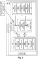
- Figure 1 is a flowchart of a method of generating an artifacts-removal logic according to one exemplary embodiment of the invention. The method can be performed, for example, by an image processing system according to a further embodiment of the invention that is depicted in figure 2 . In the following, the method of fig. 1 will be described by making reference to figure 2 .
- FIG. 2 shows an image analysis system 200.
- the system comprises a data processing system 202 with one or more processors 228, e.g. a standard desktop computer system, a notebook, a tablet computer or a server computer system.
- the image analysis system 200 comprises or is operatively coupled to an image acquisition system 204, e.g. a brightfield or fluorescence microscope or a slide scanner.
- an image acquisition system comprises a camera 212.
- the data processing system 202 comprises an interface for receiving the digital images of tissue slides captured by camera 212.
- the interface can be a network connection, an USB stick, a CD-ROM drive or the like.
- the processing system 202 comprises a non-volatile storage medium 240 which stores a plurality of original images 208.
- the original images can be RGB images or grayscale images as generated by the camera 212 are can be preprocessed images whose resolution, contrast, color space or other feature may differ from the image that was originally captured by the camera.
- the storage medium may further comprise a plurality of artifact generation logics 230-236 which can respectively be implemented as standalone software applications.
- the artifact generation logics 230-236 are implemented as components of a single software application.
- a user is enabled to specifically select one or more of the artifact generation logics for generating degraded images comprising a single specific type of artifact or comprising two or more artifacts which were generated according to one or more predefined chronological sequences of artifact generation.
- Figure 2 shows only a subset of the artifact generation logics described herein: a stitching-artifact-generation-logic 230, a line-artifact-generation-logic 232, a speckle-artifact-generation-logic 234, and an unspecific-staining-artifact-generation-logic 236. Further artifact generation logics or a different subset of artifact generation logics described herein may be comprised in the data processing systems of other embodiments. Depending on the embodiment and/or on the type of artifact, the respective artifact-generation-logic can be specified manually or automatically based on a machine learning approach on tissue images comprising the "real" artifact.
- the artifact-generation-logic can be in specified once for a particular type of artifact, or can be specified once for a particular type of image acquisition system 204, or can be specified once for an individual image acquisition system.
- the stitching-artifact-generation-logic 230 can be obtained specifically for a particular type of microscope or even for an individual microscope system by acquiring calibration images via a particular image acquisition system and fitting a square filter or other mathematical function such that the filter faithfully reproduces the stitching pattern observed within the calibration images (not shown).
- the original images 208 are high quality images which are basically free of image artifacts, or at least are basically free of image artifacts of an artifact type that shall be artificially generated by one of the artifact-generation-logics in the following steps.
- the image analysis system applies one of the image-artifact-generation-logics 230, 232, 234, 236 on each of the original images 208.
- an artificially degraded image is generated.
- the stitching-artifact-generation-logic 230 is applied on an original image, the resulting degraded image will show a stitching pattern that is added, superimposed, multiplied or otherwise combined by the artifact-generation-logic 230 with the pixels of the original image.
- the generation of a degraded version of an originally received image can be performed right after or during the image acquisition by an image acquisition system or can be performed many days after the images were acquired.
- a training data set is obtained that comprises the original images 208 and the respectively (single-fold) degraded images 210.A.
- an artifacts removal logic 218 is generated.
- the generation of the artifacts-removal-logic 218 comprises a step 104 of training a machine learning logic that encodes an artifacts-removal logic on the original images 208 and the degraded images 210 and returning, in step 106, the trained machine-learning logic 218.
- the generated artifacts removal logic 218 will basically be configured for selectively removing, via the stitching-artifact-removal-logic 220, stitching artifacts of a particular camera or camera type.
- the artifacts removal logic will not be able to remove line artifacts, speckle artifacts or the like.
- the artifacts removal logic 218 will be trained on an information-enriched training data set and will be adapted to remove artifacts of multiple different types.
- the training data set that is used for generating the respective artifact-removal logics 220-226 comprises meta-data being descriptive of the particular artifact generation logic that generated a particular degraded image from a particular one of the original images 208.
- the artifacts-removal logic 218 is configured to solely and selectively remove artifacts of a particular, single artifact type from an image.
- the artifacts removal logic 218 comprises a plurality of functionalities 220, 222, 224, 226 which are respectively trained and adopted to remove image artifacts of a particular type from an image.
- each of the artifact-removal logics 220-226 is generated by training an untrained version of a machine learning logic on training data selectively comprising image artifacts of a particular type.
- the generated, trained machine learning logic 220-226 are later combined into a single software application which allows the user to remove artifacts of multiple different types from an input image.
- the artifact-generation-logics 230-236 are not only applied once on the original images for generating single-fold degraded images 210.A. Rather, the image analysis system can be configured for applying the artifact-generation-logics sequentially, whereby the degraded image output by any one of the artifact-generation-logics in the sequence is used as input by the following artifact generation logics.
- the stitching-artifact-generation-logic 230 can read an original image 208 from the storage medium 240 and output a first intermediate image comprising a stitching artifact. The first intermediate image is then used as input by the line-artifact-generation-logic 232 for generating a second intermediate image which again is used as input for a further artifact-generation-logic.
- a user may specify the sequence of the artifact-generation-logics applied for generating multi-forwards degraded images 210.B manually.
- the user will specify the sequence of artifact generation operations such that the sequence represents the "real" chronological sequence of artifact generation that is expected to occurred during the staining and image acquisition.
- the image analysis system 200 automatically determines, for a given set or subset of artifact-generation-logics 230-236, many or all of the combinatorially possible sequences of applying the way a artifact-generation-logics.
- a training data set is generated that comprises the original images 208 and multi-fold degraded images 210.B , whereby at least some of the multi-fold degraded images have been created by the same set of artifact-generation-logics but based on different chronological sequences.
- This may be beneficial, because the chronological sequence of artifact generation may differ from case to case and a training data set that comprises many different chronological sequences of applying artifact types may allow the artifacts-removal logic 218 to "learn" many different sequences of removing artifacts from images.
- each of the artifacts removal logics 220-226 is implemented as a fully convolutional neural network. According to other embodiments, the combined artifacts removal logic 218 is implemented as a single fully convolutional neural network.
- the machine-learning-logic that is employed for learning the artifacts removal logic for individual or all artifact types is a neural network having a network architecture that is described, for example in Long, Jonathan, Evan Shelhamer, and Trevor Darrell. "Fully convolutional networks for semantic segmentation.” Proceedings of the IEEE Conference on Computer Vision and Pattern Recognition, 2015 .
- the network is a fully convolutional network trained end-to-end and pixels-to-pixels.
- the network can be generated by adapting contemporary classification networks such as AlexNet, the VGG net, and GoogLeNet into fully convolutional networks.
- the fully convolutional network is adapted for learning how to remove an artifact or a particular type by applying a model-based artifacts-removal algorithm on a degraded version of an image for generating an automatically reconstructed image, comparing the original image with the reconstructed image and, in case the difference is too high (e.g. exceeds a threshold), modifying the model such that the difference between the reconstructed image and the original image is minimized.
- the machine learning logic "learns" a model that is capable of removing artifacts of a particular type from an image.
- the machine learning logic 218, 220, 222, 224, 226 is implemented as a "denoising autoencoder" with at least one type of noise artifact model corresponding to the noise artifact types described herein.
- the trained machine-learning logic (“trained denoising encoder") is adapted to remove artifacts of this particular type from an input image.
- the network architecture can consist of a Deep Convolutional Neural Network setup with encoder and decoder mechanisms e.g. FCN-8s (in Long, Jonathan, Evan Shelhamer, and Trevor Darrell.
- the training of the machine-learning logic 218, 220-226 comprises inputting each artificially degraded image together with the respective original non-degraded image to enable the autoencoder to learn to recreate the original image from the "degraded" image.
- the artifact generation logics 230-236 are specified manually or are generated automatically or semi-automatically based on a machine learning approach.
- the stitching-artifact-generation-logic can be obtained by automatically learning a square filter from one or more images taken by a camera of a particular IAS of an empty slide.
- the salt-and-pepper noise generation function can be specified explicitly by a programmer.
- FIG. 3 is a digital tissue image depicting a "real" tissue fold artifact.
- This type of image artifact is often the result of the use of blunt knifes during tissue cutting or of handling errors during the slide mounting.
- a tissue-forward-artifact-generation logic is provided which is configured to automatically add an artificial tissue-fold artifact on an input image for generating a degraded version of the image.
- the generation of the tissue-fold artifact comprises virtually cutting the original image into image parts, overlaying the image parts such that the parts overlay along the cutting line, e.g. for an overlay margin of about 3 to 10 pixels.
- the resulting degraded image looks very similar to an image comprising a "real" tissue fold artifact.
- Figure 4 is a digital tissue image with a "real" speckle noise artifact.
- a speckle noise is often caused by dust in the camera objects or on the cover slide of a tissue slide. Speckle noise can also be generated by bad pixels in the sensor cells of a camera.
- a speckle-artifact-generation-logic 234 implements a salt-and-pepper-noise generation function. This function is capable of faithfully reproducing the speckle noise often observed in digital pathology images. Preferably, the function randomizes the radii of the speckles.
- Figure 5 is a digital tissue image with a line artifact caused by an air bubble.
- a line-artifact-generation logic 232 is configured to randomly select polynomial parameter of different orders, to generate a black line in accordance with that parameters and with the typical thickness of air bubble margins in a digital image.
- Figure 6 is a digital tissue image with a stitching artifact.
- a "stitching artifact” or “stitching-noise-artifact” is an image artifact generated by the optics or mechanics of the image acquisition system 204, whereby the image acquisition system can in particular be a slide scanner.
- a stitching-artifact-generation-logic 230 implements a square filter that is applied on any input image received by the program logic 230, thereby generating and returning a degraded image comprising a simulated stitching artifact.
- the square filter is obtained empirically by analyzing the image of an empty slide obtained by a particular image acquisition system.
- the square filter is automatically or manually fitted such that it faithfully reproduces the observed stitching pattern of the image acquisition system.
- the stitching-artifacts-generation-logics 230 automatically generates, for each of a plurality of original images, a respective degraded image comprising the simulated stitching artifact of a particular image acquisition system.
- the original images and the degraded images are used as training data set for training and stitching-artifact-removal logic 220 that is capable of selectively removing the stitching artifact generated by a particular image acquisition system or type of image acquisition system.
- Figure 7 is a digital tissue image with a "real" non-specific staining artifact.
- Non-specific staining artifacts can be simulated, e.g. by a program logic 236, by applying a color-specific salt-and-pepper speckle noise generation function, whereby the color of this function corresponds to the type of stain whose unspecific staining artifacts shall be simulated and removed.
- the program logic 226 of the image acquisition system is generated based on a machine learning approach from a training data sets comprising original images 208 and artificially degraded images generated by program logic 236.
- the program logic 226 is configured to selectively remove unspecific staining artifacts of a particular stain from a digital pathology image.
- Figure 8 is a digital tissue image with a "real" bad-focus artifact that is the result of a microscope focus loss.
- degraded images comprising bad-focus noise can be automatically created by modeling a point spread function (PSF) or a Gaussian approximation of a PSF for a particular image acquisition system, e.g. for a particular microscope or microscope type.
- PSF point spread function
- Gaussian approximation of a PSF for a particular image acquisition system, e.g. for a particular microscope or microscope type.
- Figure 9 depicts a digital tissue image with a stitching artifact created with image acquisition system specific parameters
- Figure 10 is a block diagram of a "naive" Neural Network architecture used as a machine learning logic according to embodiments of the invention.
- the depicted network architecture can be trained to learn the generation of an artifact of a single artifact type.
- the network architecture can be trained to generate a predefined sequence of artifacts of different types.
- the network architecture depicted in this figure can be trained to remove an artifact of a particular artifact type or to remove multiple artifacts of different types in a predefined sequence. More layers can be inserted or removed to increase or decrease the complexity of the network. By adding and removing layers from the network and by testing the accuracy of the trained network on a reference data set, a network architecture with an optimum number of layers can be determined experimentally.
- Figure 11 is a block diagram of an "auxiliary loss" Neural Network architecture used as machine learning logic in some other examples of the invention.
- the network architecture depicted in figure 11 can basically be used in the same manner and for the same purposes as the architecture depicted in figure 10 .
- Both the "na ⁇ ve network” and the “auxiliary loss” network architecture can be used as the program logic that learns to create and/or remove a particular artifact type. Both the "na ⁇ ve network” and the “auxiliary loss” network architecture can be used as the program logic that learns to create and/or remove sequences of artifacts.
- the "auxiliary loss” network allows a tighter control of the training process, because sub-sets of layers in the network have assigned a "teacher" on their own which may allow to achieve a training of said sub-set of layers to generate or remove a particular artifact type.
- Figure 12a is a block diagram of a basic encoder unit as used, for example, in a neural network depicted in figure 10 or 11 .
- the basic encoder unit forms a sequence of normalization layers wherein a batch normalization layer precedes the rectification layer (rectified linear unit - ReLU) layer.
- Figure 12b is a block diagram of a Residual Encoder Unit as used, for example, in a neural network depicted in figure 10 or 11 .
- the basic encoder unit forms a sequence of normalization layers wherein the ReLU layers precede the batch normalization layer.
- Figure 12c is a block diagram of a Basic Decoder Unit that has a similar architecture like the unit depicted in figure 12a . In addition, it comprises an unsampling layer.
- Each Layer depicted in figures 12a-12c has a function in a network, e.g. in one of the networks depicted in figures 10 and 11 .
- convolotion2d applies 2d convolutional filters
- batch normalization normalizes the gradients during training
- upsampling makes the image bigger
- pooling downsamples the image.
- the layers can respectively comprise parameters whose values are learned (optimized) during the training phase.
Landscapes
- Engineering & Computer Science (AREA)
- Theoretical Computer Science (AREA)
- Physics & Mathematics (AREA)
- General Physics & Mathematics (AREA)
- Health & Medical Sciences (AREA)
- Software Systems (AREA)
- Mathematical Physics (AREA)
- General Engineering & Computer Science (AREA)
- Data Mining & Analysis (AREA)
- Evolutionary Computation (AREA)
- General Health & Medical Sciences (AREA)
- Artificial Intelligence (AREA)
- Computing Systems (AREA)
- Computational Linguistics (AREA)
- Biophysics (AREA)
- Biomedical Technology (AREA)
- Life Sciences & Earth Sciences (AREA)
- Molecular Biology (AREA)
- Medical Informatics (AREA)
- Nuclear Medicine, Radiotherapy & Molecular Imaging (AREA)
- Computer Vision & Pattern Recognition (AREA)
- Radiology & Medical Imaging (AREA)
- Epidemiology (AREA)
- Primary Health Care (AREA)
- Public Health (AREA)
- Image Analysis (AREA)
- Image Processing (AREA)
- Investigating Or Analysing Biological Materials (AREA)
Claims (17)
- Procédé de fourniture d'une logique de programme conçue pour éliminer les artéfacts d'images numériques de tissus, le procédé comprenant :- la fourniture, pour chacun d'une pluralité de types d'artéfacts différents, d'une logique de génération d'artéfact (230-236) respective configurée pour générer spécifiquement ledit type particulier d'artéfact ;- la génération, pour chacune d'une pluralité d'images initiales (208) représentant respectivement un échantillon de tissu, d'une première image artificiellement dégradée (210.A) en appliquant une première logique de génération d'artéfact d'image (230-236) sur chacune des images initiales, la première logique de génération d'artéfact d'image étant configurée pour générer spécifiquement un premier type d'artéfact, les premières logiques de génération d'artéfact d'image étant configurées pour générer spécifiquement un premier type d'artéfact, les premières logiques de génération d'artéfact d'image étant A) une logique de génération d'artéfact d'image spécifique d'un système d'acquisition d'image ou B) une logique de génération d'artéfact de coloration de tissu ;- l'application, selon une première séquence, des différentes logiques de génération d'artéfact d'image sur chacune des images initiales, moyennant quoi la logique de génération d'artéfact d'image (230) au niveau d'une première position au sein de la première séquence prend chacune des images initiales en tant qu'entrée et dans lequel l'image dégradée délivrée par ladite logique de génération d'artéfact d'image (230) et par une quelconque logique de génération d'artéfact d'image au niveau d'une position suivante au sein de la première séquence est utilisée en tant qu'image d'entrée par la logique suivante des différentes logiques de génération d'artéfact d'image dans la première séquence, générant ainsi, pour chacune des images initiales, une première image dégradée plusieurs fois (210.B) ;- la génération d'une logique de programme (218) configurée pour éliminer séquentiellement les artéfacts de chacun des multiples types différents d'images numériques de tissus, la génération comprenant :∘ l'entraînement de logiques d'apprentissage machine configurées pour éliminer les artéfacts des multiples types différents afin de coder une logique d'élimination d'artéfacts à étapes multiples, l'entraînement étant effectué sur au moins les images initiales et leurs images dégradées plusieurs fois (210.B) respectivement générées ; et∘ l'utilisation de ladite logique d'élimination d'artéfacts à étapes multiples entraînée en tant que logique de programme (218),dans lequel l'entraînement des logiques d'apprentissage machine comprend en outre :▪ l'entraînement, pour chacun des différents types d'artéfacts, d'une version non entraînée d'une logique d'apprentissage machine qui code une logique d'élimination d'artéfacts (220-226) respective sur les images initiales (208) et leurs premières images artificiellement dégradées (210.A) respectivement générées ;▪ le renvoi de chacune des logiques d'apprentissage machine entraînées en tant que composant de la logique de programme (218).
- Procédé selon la revendication 1 option A), dans lequel l'une des logiques de génération d'artéfact d'image est une logique de génération d'artéfact de mauvaise mise au point, le procédé comprenant en outre la création de la logique de génération d'artéfact de mauvaise mise au point, la création comprenant :- l'ajout de billes de taille connue sur une lame porte-objets ;- la prise, par le système d'acquisition d'image qui est utilisé pour capturer la pluralité d'images initiales (208), d'une image numérique de la lame porte-objets avec les billes ;- l'analyse de ladite image numérique pour déterminer automatiquement un motif optique et sa taille générés par au moins l'une des billes ;- l'identification d'une fonction conçue pour simuler la génération du motif de la taille déterminée à partir d'un point ayant la taille de bille connue ; et- la création de la logique de génération d'artéfact de mauvaise mise au point en intégrant la fonction identifiée dans un code exécutable par machine.
- Procédé selon la revendication 2, la fonction conçue pour simuler la génération du motif étant une fonction d'étalement du point ou un filtre gaussien.
- Procédé selon la revendication 1 option A), dans lequel l'une des logiques de génération d'artéfact d'image est une logique de génération d'artéfact d'assemblage, le procédé comprenant en outre la création de la logique de génération d'artéfact d'assemblage, la création comprenant :- la prise, par le système d'acquisition d'image qui est utilisé pour capturer la pluralité d'images initiales (208), d'une image numérique d'une lame porte-objets vide ;- l'analyse de l'image numérique de la lame porte-objets vide pour créer automatiquement un filtre carré qui est configuré pour simuler l'artéfact d'assemblages généré par le système d'acquisition d'image ; et- la création de la logique de génération d'artéfact d'assemblage en intégrant le filtre carré dans un code exécutable par machine.
- Procédé selon la revendication 1 option A), dans lequel l'une des logiques de génération d'artéfact d'image est une logique de génération d'artéfact de déphasage de teinte configurée pour générer spécifiquement des artéfacts de déphasage de teinte qui sont générés par le système d'acquisition d'image, le procédé comprenant en outre la création de la logique de génération d'artéfact de déphasage de teinte, la création comprenant :- la prise, par le système d'acquisition d'image qui est utilisé pour capturer la pluralité d'images initiales (208), d'une image numérique d'une lame porte-objets vide ;- l'analyse de l'image numérique de la lame porte-objets vide pour créer automatiquement un filtre de déphasage de teinte qui est configuré pour simuler l'artéfact de déphasage de teinte généré par le système d'acquisition d'image ; et- la création de la logique de génération d'artéfact de déphasage de teinte en intégrant le filtre de déphasage de teinte dans un code exécutable par machine.
- Procédé selon la revendication 1 option A), comprenant en outre :- la fourniture d'une pluralité de systèmes d'acquisition d'image ;pour chacun de la pluralité de systèmes d'acquisition d'image :- la création de la logique de génération d'artéfact d'image de mauvaise mise au point, de déphasage de teinte ou d'assemblage selon l'une quelconque des revendications 2 à 5, la logique de génération d'artéfact d'image étant spécifique dudit système d'acquisition d'image ;- la capture, par ledit système d'acquisition d'image, d'une pluralité d'images initiales d'un échantillon de tissu ;- la génération, pour chacune de la pluralité d'images initiales (208) d'une image artificiellement dégradée (210.A) respective en appliquant la logique de génération d'artéfact de mauvaise mise au point, de déphasage de teinte ou d'assemblage spécifique de l'acquisition d'image (230-236) crée sur chacune des images initiales ;- la génération d'une logique de programme spécifique du système d'acquisition d'image (218) configurée pour éliminer les artéfacts des images numériques de tissus capturées par ledit système d'acquisition d'image, la génération comprenant l'entraînement d'une version non entraînée d'une première logique d'apprentissage machine qui code une première logique d'élimination d'artéfacts (220-226) sur les images initiales (208) et leurs premières images dégradées (210) respectivement générées ; et le renvoi de la première logique d'apprentissage machine entraînée en tant que logique de programme spécifique du système d'acquisition d'image (218) ou en tant que composant de celle-ci.
- Procédé selon la revendication 1 option B), dans lequel l'une des logiques de génération d'artéfact d'image est une logique de génération d'artéfact de pli de tissu configurée pour générer des artéfacts de pli de tissu dans une image d'entrée, le procédé comprenant en outre la création de la logique de génération d'artéfact de pli de tissu, la création comprenant :- la génération d'au moins deux parties d'image de chacune d'une ou plusieurs images d'entrée en découpant chaque image d'entrée sur une ligne sélectionnée de manière aléatoire ;- la superposition des au moins deux parties d'image le long de la ligne de sorte à créer un chevauchement des deux parties d'image le long de la ligne de la découpe ; et- la fusion du chevauchement des parties d'image, générant ainsi une version dégradée de l'image d'entrée ;- l'entraînement d'une logique d'apprentissage machine sur la ou les images d'entrée et l'image dégradée pour fournir une logique d'apprentissage machine entraînée conçue pour simuler l'image dégradée, fusionnée de l'image d'entrée qui a été divisée pour générer l'image dégradée, fusionnée ; et- la création de la logique de génération d'artéfact de pli de tissu en intégrant ladite logique d'apprentissage machine entraînée dans un code exécutable par machine.
- Procédé selon la revendication 1 option B, dans lequel l'une des logiques de génération d'artéfact d'image est une logique de génération d'artéfact de ligne conçue pour générer spécifiquement des artéfacts de ligne dans une image d'entrée, la longueur, l'épaisseur et/ou la courbure des artéfacts de ligne représentant des cheveux, les contours de bulles de gaz et/ou des fibres textiles, le procédé comprenant en outre la création de la logique de génération d'artéfact de ligne, la création comprenant :- la génération d'une pluralité de courbes polynomiales en utilisant des valeurs générées de manière aléatoire en tant que paramètres de courbe ;- l'insertion de lignes noires le long des coordonnées des courbes polynomiales dans une ou plusieurs images d'entrée, générant ainsi une version dégradée de l'image d'entrée ;- l'entraînement d'une logique d'apprentissage machine sur la ou les images d'entrée et l'image dégradée générée à partir de celles-ci pour fournir une logique d'apprentissage machine entraînée conçue pour simuler les artéfacts de ligne ; et- la création de la logique de génération d'artéfact de ligne en intégrant ladite logique d'apprentissage machine entraînée dans un code exécutable par machine.
- Procédé selon la revendication 1 option B), dans lequel l'une des logiques de génération d'artéfact d'image est une logique de génération de bruit de couleur conçue pour générer spécifiquement des artéfacts consistant en un bruit optique d'une couleur ou d'une combinaison de couleurs définie dans une image d'entrée, le procédé comprenant en outre la création de la première logique de génération d'artéfact de bruit de couleur, la création comprenant :- la spécification d'une fonction poivre et sel spécifique d'une couleur conçue pour simuler des régions de lames porte-objets de tissu avec une coloration résiduelle ; et- la création de la logique de génération d'artéfact de bruit de couleur en intégrant ladite fonction poivre et sel spécifique d'une couleur dans un code exécutable par machine.
- Procédé selon l'une quelconque des revendications précédentes, comprenant en outre :- l'application, selon au moins une seconde séquence, des différentes logiques de génération d'artéfact d'image sur les images initiales, moyennant quoi la logique de génération d'artéfact d'image au niveau de la première position au sein de la seconde séquence prend chacune des images initiales en tant qu'entrée et dans lequel l'image dégradée délivrée par ladite logique de génération d'artéfact d'image et une quelconque logique de génération d'artéfact d'image au niveau d'une position suivante au sein de la seconde séquence est utilisée en tant qu'image d'entrée par la logique suivante des différentes logiques de génération d'artéfact d'image dans la seconde séquence, générant ainsi, pour chacune des images initiales, une seconde image dégradée plusieurs fois ;
dans lequel l'entraînement de la version non entraînée de la logique d'apprentissage machine qui code la logique d'élimination d'artéfacts à étapes multiples est effectué sur au moins les images initiales et leurs première et seconde images dégradées plusieurs fois respectivement générées. - Procédé selon l'une quelconque des revendications précédentes, comprenant en outre :- la création de manière automatique d'une pluralité de séquences des différentes logiques de génération d'artéfact d'image, chacune de la pluralité de séquences comprenant différentes logiques de génération d'artéfact d'image au niveau de la première, de la deuxième et d'au moins une troisième position en permutant les positions des logiques de génération d'artéfact d'image au sein de la séquence respective ;- l'application, pour chacune de la pluralité de séquences, des logiques de génération d'artéfact d'image de ladite séquence sur les images initiales, moyennant quoi la logique de génération d'artéfact d'image au niveau de la première position au sein de ladite séquence prend chacune des images initiales en tant qu'entrée et dans lequel l'image dégradée délivrée par ladite logique de génération d'artéfact d'image et une quelconque logique de génération d'artéfact d'image au niveau d'une position suivante dans ladite séquence est utilisée en tant qu'image d'entrée par la logique suivante des différentes logiques de génération d'artéfact d'image dans ladite séquence, générant ainsi, pour chacune des images initiales, et pour chacune de la pluralité de séquences, une image dégradée plusieurs fois ;
l'entraînement de la version non entraînée de la logique d'apprentissage machine qui code une logique d'élimination d'artéfacts à étapes multiples étant effectué sur au moins les images initiales, la pluralité de séquences et leurs images dégradées plusieurs fois respectivement générées. - Procédé selon l'une quelconque des revendications précédentes, la première séquence étant définie manuellement et représentant la séquence typique de génération d'artéfact dans un flux de tâches de coloration de tissu et d'acquisition d'image.
- Procédé selon l'une quelconque des revendications précédentes, dans lequel la logique d'apprentissage machine entraînée pour fournir la logique de génération d'artéfact d'image et/ou pour fournir la logique de programme configurée pour éliminer les artéfacts est un réseau neuronal.
- Procédé selon l'une quelconque des revendications précédentes, dans lequel la logique d'apprentissage machine entraînée pour fournir la logique de génération d'artéfact d'image et/ou pour fournir la logique de programme configurée pour éliminer les artéfacts est un auto-encodeur.
- Procédé de correction d'image pour des images de tissus représentant un échantillon biologique, le procédé comprenant :- la réception d'une image numérique de l'échantillon biologique, l'image numérique comprenant un artéfact ;- l'application de la logique de programme générée selon l'une quelconque des revendications 1 à 14 sur l'image numérique reçue pour générer une image à artéfact corrigé ; et- le renvoi de l'image à artéfact corrigé.
- Programme d'ordinateur comprenant des instructions lisibles par ordinateur qui, lorsqu'elles sons exécutées par un processeur (228), amènent le processeur à effectuer un procédé selon l'une quelconque des revendications précédentes.
- Système d'analyse d'image (200) comprenant :- un support de stockage (240) comprenant une pluralité d'images initiales (208), chaque image initiale représentant un tissu ;- un processeur (228) configuré pour :- fournir, pour chacun d'une pluralité de types d'artéfacts différents, une logique de génération d'artéfact (230-236) respective configurée pour générer spécifiquement ledit type particulier d'artéfact ;- générer, pour chacune d'une pluralité d'images initiales (208) représentant respectivement un échantillon de tissu, une première image (210.A) artificiellement dégradée en appliquant une première logique de génération d'artéfact d'image (230-236) sur chacune des images initiales, la première logique de génération d'artéfact d'image étant configurée pour générer spécifiquement un premier type d'artéfact, les premières logiques de génération d'artéfact d'image étant configurées pour générer spécifiquement un premier type d'artéfact, les premières logiques de génération d'artéfact d'image étant A) une logique de génération d'artéfact d'image spécifique d'un système d'acquisition d'image ou B) une logique de génération d'artéfact de coloration de tissu ;- appliquer, selon une première séquence, les différentes logiques de génération d'artéfact d'image sur chacune des images initiales, moyennant quoi la logique de génération d'artéfact d'image (230) au niveau d'une première position au sein de la première séquence prend chacune des images initiales en tant qu'entrée et dans lequel l'image dégradée délivrée par ladite logique de génération d'artéfact d'image (230) et par une quelconque logique de génération d'artéfact d'image au niveau d'une position suivante au sein de la première séquence est utilisée en tant qu'image d'entrée par la logique suivante des différentes logiques de génération d'artéfact d'image dans la première séquence, générant ainsi, pour chacune des images initiales, une première image dégradée plusieurs fois (210.B) ;- générer une logique de programme (218) configurée pour éliminer séquentiellement les artéfacts de chacun des multiples types différents des images de tissus numériques, la génération comprenant :▪ l'entraînement, pour chacun des différents types d'artéfacts, d'une version non entraînée d'une logique d'apprentissage machine qui code une logique d'élimination d'artéfacts (220-226) respective sur les images initiales (208) et leurs premières images artificiellement dégradées (210.A) respectivement générées ;▪ le renvoi de chacune des logiques d'apprentissage machine entraînées en tant que composant de la logique de programme (218) ;▪ l'entraînement d'une logique d'apprentissage machine qui code une logique d'élimination d'artéfacts à étapes multiples, l'entraînement étant effectué sur au moins les images initiales et leurs premières images dégradées plusieurs fois (210.B) respectivement générées ;▪ l'utilisation de ladite logique d'élimination d'artéfacts à étapes multiples entraînée en tant que logique de programme (218).
Applications Claiming Priority (2)
| Application Number | Priority Date | Filing Date | Title |
|---|---|---|---|
| EP17192764 | 2017-09-22 | ||
| PCT/EP2018/075708 WO2019057944A1 (fr) | 2017-09-22 | 2018-09-21 | Élimination d'artéfacts à partir d'images de tissu |
Publications (3)
| Publication Number | Publication Date |
|---|---|
| EP3685347A1 EP3685347A1 (fr) | 2020-07-29 |
| EP3685347B1 true EP3685347B1 (fr) | 2024-08-07 |
| EP3685347C0 EP3685347C0 (fr) | 2024-08-07 |
Family
ID=59955498
Family Applications (1)
| Application Number | Title | Priority Date | Filing Date |
|---|---|---|---|
| EP18769411.2A Active EP3685347B1 (fr) | 2017-09-22 | 2018-09-21 | Élimination d'artéfacts d'images de tissus |
Country Status (5)
| Country | Link |
|---|---|
| US (2) | US11521301B2 (fr) |
| EP (1) | EP3685347B1 (fr) |
| JP (1) | JP7022203B2 (fr) |
| CN (1) | CN111226257B (fr) |
| WO (1) | WO2019057944A1 (fr) |
Families Citing this family (53)
| Publication number | Priority date | Publication date | Assignee | Title |
|---|---|---|---|---|
| US11157014B2 (en) | 2016-12-29 | 2021-10-26 | Tesla, Inc. | Multi-channel sensor simulation for autonomous control systems |
| US10678244B2 (en) | 2017-03-23 | 2020-06-09 | Tesla, Inc. | Data synthesis for autonomous control systems |
| US11409692B2 (en) | 2017-07-24 | 2022-08-09 | Tesla, Inc. | Vector computational unit |
| US10671349B2 (en) | 2017-07-24 | 2020-06-02 | Tesla, Inc. | Accelerated mathematical engine |
| US11157441B2 (en) | 2017-07-24 | 2021-10-26 | Tesla, Inc. | Computational array microprocessor system using non-consecutive data formatting |
| US11893393B2 (en) | 2017-07-24 | 2024-02-06 | Tesla, Inc. | Computational array microprocessor system with hardware arbiter managing memory requests |
| US12307350B2 (en) | 2018-01-04 | 2025-05-20 | Tesla, Inc. | Systems and methods for hardware-based pooling |
| US11561791B2 (en) | 2018-02-01 | 2023-01-24 | Tesla, Inc. | Vector computational unit receiving data elements in parallel from a last row of a computational array |
| US10706328B2 (en) * | 2018-05-07 | 2020-07-07 | Google Llc | Focus-weighted, machine learning disease classifier error prediction for microscope slide images |
| CN108875787B (zh) * | 2018-05-23 | 2020-07-14 | 北京市商汤科技开发有限公司 | 一种图像识别方法及装置、计算机设备和存储介质 |
| US11215999B2 (en) | 2018-06-20 | 2022-01-04 | Tesla, Inc. | Data pipeline and deep learning system for autonomous driving |
| US11361457B2 (en) | 2018-07-20 | 2022-06-14 | Tesla, Inc. | Annotation cross-labeling for autonomous control systems |
| US11636333B2 (en) | 2018-07-26 | 2023-04-25 | Tesla, Inc. | Optimizing neural network structures for embedded systems |
| US11820289B2 (en) * | 2018-07-31 | 2023-11-21 | Sony Semiconductor Solutions Corporation | Solid-state imaging device and electronic device |
| WO2020027233A1 (fr) | 2018-07-31 | 2020-02-06 | ソニーセミコンダクタソリューションズ株式会社 | Dispositif d'imagerie et système de commande de véhicule |
| JP7443366B2 (ja) * | 2018-08-07 | 2024-03-05 | メタ プラットフォームズ, インク. | 画像強調のための人工知能技法 |
| US11562231B2 (en) | 2018-09-03 | 2023-01-24 | Tesla, Inc. | Neural networks for embedded devices |
| WO2020077117A1 (fr) | 2018-10-11 | 2020-04-16 | Tesla, Inc. | Systèmes et procédés d'apprentissage de modèles de machine au moyen de données augmentées |
| US11196678B2 (en) | 2018-10-25 | 2021-12-07 | Tesla, Inc. | QOS manager for system on a chip communications |
| US11011257B2 (en) * | 2018-11-21 | 2021-05-18 | Enlitic, Inc. | Multi-label heat map display system |
| US11816585B2 (en) | 2018-12-03 | 2023-11-14 | Tesla, Inc. | Machine learning models operating at different frequencies for autonomous vehicles |
| US11537811B2 (en) | 2018-12-04 | 2022-12-27 | Tesla, Inc. | Enhanced object detection for autonomous vehicles based on field view |
| US11610117B2 (en) | 2018-12-27 | 2023-03-21 | Tesla, Inc. | System and method for adapting a neural network model on a hardware platform |
| CN109743626B (zh) * | 2019-01-02 | 2022-08-12 | 京东方科技集团股份有限公司 | 一种图像显示方法、图像处理方法和相关设备 |
| US10997461B2 (en) | 2019-02-01 | 2021-05-04 | Tesla, Inc. | Generating ground truth for machine learning from time series elements |
| US11150664B2 (en) | 2019-02-01 | 2021-10-19 | Tesla, Inc. | Predicting three-dimensional features for autonomous driving |
| US11567514B2 (en) | 2019-02-11 | 2023-01-31 | Tesla, Inc. | Autonomous and user controlled vehicle summon to a target |
| US10956755B2 (en) | 2019-02-19 | 2021-03-23 | Tesla, Inc. | Estimating object properties using visual image data |
| US11900566B1 (en) * | 2019-06-26 | 2024-02-13 | Gopro, Inc. | Method and apparatus for convolutional neural network-based video denoising |
| CN110378976B (zh) * | 2019-07-18 | 2020-11-13 | 北京市商汤科技开发有限公司 | 图像处理方法及装置、电子设备和存储介质 |
| US11257191B2 (en) * | 2019-08-16 | 2022-02-22 | GE Precision Healthcare LLC | Systems and methods for deblurring medical images using deep neural network |
| CN110634103A (zh) * | 2019-08-28 | 2019-12-31 | 天津大学 | 基于生成对抗网络的图像去马赛克方法 |
| US11288775B2 (en) * | 2019-11-27 | 2022-03-29 | GE Precision Healthcare LLC | Methods and systems for parametric noise modulation in x-ray imaging |
| EP4107569B1 (fr) * | 2020-02-17 | 2025-10-22 | Charité Universitätsmedizin Berlin - Körperschaft des öffentlichen Rechts | Microscopie de restauration bimode |
| DE102020105697B3 (de) * | 2020-03-03 | 2021-03-04 | Carl Zeiss Meditec Ag | Computerimplementiertes Verfahren zum Auffinden möglicher Artefakte in einem virtuell eingefärbten Histologiebild |
| US11620730B2 (en) * | 2020-03-23 | 2023-04-04 | Realsee (Beijing) Technology Co., Ltd. | Method for merging multiple images and post-processing of panorama |
| CN111595850B (zh) * | 2020-04-27 | 2022-07-15 | 平安科技(深圳)有限公司 | 切片缺陷检测方法、电子装置及可读存储介质 |
| CN111681187B (zh) * | 2020-06-13 | 2023-06-16 | 厦门美图之家科技有限公司 | 降彩噪方法、装置、电子设备和可读存储介质 |
| CN114616587B (zh) * | 2020-09-28 | 2025-04-04 | 谷歌有限责任公司 | 基于学习的镜头眩光移除 |
| CN112434554B (zh) * | 2020-10-16 | 2023-08-04 | 中科院成都信息技术股份有限公司 | 一种基于异质化缩减的云状图像识别方法及系统 |
| US11954932B2 (en) * | 2020-10-16 | 2024-04-09 | Bluebeam, Inc. | Systems and methods for automatic detection of features on a sheet |
| CN114913108B (zh) * | 2021-01-29 | 2025-09-05 | 京东方科技集团股份有限公司 | 显示基板的图像分类方法和装置 |
| EP4105879A1 (fr) * | 2021-06-17 | 2022-12-21 | Fujitsu Limited | Procédé d'apprentissage non supervisé pour détecter les anomalies transparentes, ou difficiles à voir, dans les images |
| JP2024535985A (ja) | 2021-08-19 | 2024-10-04 | テスラ,インコーポレイテッド | シミュレートコンテンツを用いた視覚に基づくシステムの訓練 |
| US12462575B2 (en) | 2021-08-19 | 2025-11-04 | Tesla, Inc. | Vision-based machine learning model for autonomous driving with adjustable virtual camera |
| US12419602B2 (en) * | 2021-09-07 | 2025-09-23 | The Board Of Regents Of The University Of Oklahoma | Dead detector element detection |
| JP7610727B2 (ja) * | 2021-10-29 | 2025-01-08 | 株式会社日立ハイテク | 観察システム、及びそのアーチファクト補正方法 |
| WO2023128059A1 (fr) * | 2021-12-28 | 2023-07-06 | Lunit Inc. | Procédé et appareil de pureté de tumeur sur la base d'une image de diapositive pathologique |
| US12475564B2 (en) * | 2022-02-16 | 2025-11-18 | Proscia Inc. | Digital pathology artificial intelligence quality check |
| US12437981B2 (en) * | 2022-05-20 | 2025-10-07 | Sapient Bioanalytics, Llc | Adjustments of mass spectrometry signals |
| US11983874B1 (en) | 2023-07-25 | 2024-05-14 | Pramana, Inc. | Imaging device and a method for image generation of a specimen |
| DE102023119849A1 (de) * | 2023-07-26 | 2025-01-30 | Carl Zeiss Microscopy Gmbh | Mikroskopiesystem und Verfahren zum Entfernen von Bildartefakten |
| KR102692224B1 (ko) * | 2023-08-29 | 2024-08-06 | (주)바질컴퍼니 | 위치 제어가 가능한 인공 결함 데이터 생성 방법 |
Citations (1)
| Publication number | Priority date | Publication date | Assignee | Title |
|---|---|---|---|---|
| US20170213321A1 (en) * | 2016-01-22 | 2017-07-27 | Siemens Healthcare Gmbh | Deep Unfolding Algorithm For Efficient Image Denoising Under Varying Noise Conditions |
Family Cites Families (11)
| Publication number | Priority date | Publication date | Assignee | Title |
|---|---|---|---|---|
| EP2419880B1 (fr) * | 2009-04-13 | 2019-09-25 | Koninklijke Philips N.V. | Courbes de référence plausibles pour études d'imagerie dynamique avec injection d'un agent de contraste |
| DE102012206714A1 (de) * | 2011-08-10 | 2013-02-14 | Friedrich-Alexander-Universität Erlangen-Nürnberg | Verfahren, Recheneinheit, CT-System und C-Bogen-System zur Reduktion von Metallartefakten in CT-Bilddatensätzen |
| WO2014008329A1 (fr) * | 2012-07-03 | 2014-01-09 | Marseille Networks, Inc. | Système et procédé pour l'amélioration et le traitement d'une image numérique |
| US9396523B2 (en) * | 2013-07-24 | 2016-07-19 | Microsoft Technology Licensing, Llc | Image restoration cascade |
| CN104665831A (zh) * | 2013-11-29 | 2015-06-03 | 株式会社日立制作所 | 图像伪影去除方法及图像伪影去除装置 |
| US10610182B2 (en) * | 2014-01-15 | 2020-04-07 | Alara Systems, Inc | Converting low-dose to higher dose 3D tomosynthesis images through machine-learning processes |
| CN104657962B (zh) * | 2014-12-12 | 2017-08-25 | 西安电子科技大学 | 基于级联线性回归的图像超分辨重建方法 |
| US10013780B2 (en) * | 2016-02-29 | 2018-07-03 | General Electric Company | Systems and methods for artifact removal for computed tomography imaging |
| CN106803237B (zh) * | 2016-12-14 | 2019-12-20 | 银江股份有限公司 | 一种基于极限学习机的改进自适应加权平均图像去噪方法 |
| CN106952239A (zh) * | 2017-03-28 | 2017-07-14 | 厦门幻世网络科技有限公司 | 图像生成方法和装置 |
| CN107122826B (zh) * | 2017-05-08 | 2019-04-23 | 京东方科技集团股份有限公司 | 用于卷积神经网络的处理方法和系统、和存储介质 |
-
2018
- 2018-09-21 EP EP18769411.2A patent/EP3685347B1/fr active Active
- 2018-09-21 JP JP2020514984A patent/JP7022203B2/ja active Active
- 2018-09-21 WO PCT/EP2018/075708 patent/WO2019057944A1/fr not_active Ceased
- 2018-09-21 CN CN201880057545.2A patent/CN111226257B/zh active Active
- 2018-09-21 US US16/646,048 patent/US11521301B2/en active Active
-
2022
- 2022-11-10 US US18/054,337 patent/US11854168B2/en active Active
Patent Citations (1)
| Publication number | Priority date | Publication date | Assignee | Title |
|---|---|---|---|---|
| US20170213321A1 (en) * | 2016-01-22 | 2017-07-27 | Siemens Healthcare Gmbh | Deep Unfolding Algorithm For Efficient Image Denoising Under Varying Noise Conditions |
Non-Patent Citations (4)
| Title |
|---|
| DAVID EIGEN ET AL: "Restoring an Image Taken through a Window Covered with Dirt or Rain", 2013 IEEE INTERNATIONAL CONFERENCE ON COMPUTER VISION, 1 December 2013 (2013-12-01), pages 633 - 640, XP055450390, ISBN: 978-1-4799-2840-8, DOI: 10.1109/ICCV.2013.84 * |
| FOREST AGOSTINELLI ET AL: "Adaptive multi-column deep neural networks with application to robust image denoising", NIPS'13 PROCEEDINGS OF THE 26TH INTERNATIONAL CONFERENCE ON NEURAL INFORMATION PROCESSING SYSTEMS, 10 December 2013 (2013-12-10), XP055508282 * |
| JUNYUAN XIE ET AL: "Image Denoising and Inpainting with Deep Neural Networks", NIPS'12 PROCEEDINGS OF THE 25TH INTERNATIONAL CONFERENCE ON NEURAL INFORMATION PROCESSING SYSTEMS, LAKE TAHOE, NEVADA, 3 December 2012 (2012-12-03), https://papers.nips.cc/paper/4686-image-denoising-and-inpainting-with-deep-neural-networks.pdf, XP055380144 * |
| RUOHAN GAO ET AL: "On-demand Learning for Deep Image Restoration", 2017 IEEE INTERNATIONAL CONFERENCE ON COMPUTER VISION (ICCV), 1 August 2017 (2017-08-01), pages 1095 - 1104, XP055451168, ISBN: 978-1-5386-1032-9, DOI: 10.1109/ICCV.2017.124 * |
Also Published As
| Publication number | Publication date |
|---|---|
| CN111226257B (zh) | 2024-03-01 |
| CN111226257A (zh) | 2020-06-02 |
| EP3685347A1 (fr) | 2020-07-29 |
| JP2020535502A (ja) | 2020-12-03 |
| US20230064699A1 (en) | 2023-03-02 |
| US20200279354A1 (en) | 2020-09-03 |
| JP7022203B2 (ja) | 2022-02-17 |
| EP3685347C0 (fr) | 2024-08-07 |
| US11854168B2 (en) | 2023-12-26 |
| US11521301B2 (en) | 2022-12-06 |
| WO2019057944A1 (fr) | 2019-03-28 |
Similar Documents
| Publication | Publication Date | Title |
|---|---|---|
| US11854168B2 (en) | Artifacts removal from tissue images | |
| Heebner et al. | Deep learning-based segmentation of cryo-electron tomograms | |
| JP7422825B2 (ja) | 顕微鏡スライド画像のための焦点重み付き機械学習分類器誤り予測 | |
| Kanwal et al. | The devil is in the details: Whole slide image acquisition and processing for artifacts detection, color variation, and data augmentation: A review | |
| JP7346726B2 (ja) | 深層学習による位相画像の再構築 | |
| Campanella et al. | Towards machine learned quality control: A benchmark for sharpness quantification in digital pathology | |
| Jurrus et al. | Axon tracking in serial block-face scanning electron microscopy | |
| AU2016369355A1 (en) | Systems and methods of unmixing images with varying acquisition properties | |
| KR20240032031A (ko) | 블러 강건성을 제공하도록 전자 이미지를 처리하는 시스템 및 방법 | |
| Jütte et al. | Advancing dermoscopy through a synthetic hair benchmark dataset and deep learning-based hair removal | |
| US11854281B2 (en) | System, method, and computer-accessible medium for processing brain images and extracting neuronal structures | |
| Stegmaier | New methods to improve large-scale microscopy image analysis with prior knowledge and uncertainty | |
| HK40029230A (en) | Artifacts removal from tissue images | |
| HK40029230B (zh) | 组织图像中的伪像移除 | |
| Yin et al. | SpecReFlow: an algorithm for specular reflection restoration using flow-guided video completion | |
| Grothausmann et al. | Enabling Manual Intervention for Otherwise Automated Registration of Large Image Series | |
| Branciforti et al. | Hybrid Wavelet‐Deep Learning Framework for Fluorescence Microscopy Images Enhancement | |
| CN119301632B (zh) | 用于执行染色剂去卷积的系统和方法 | |
| Hajiabadi | Assisting in the Reuse of Artificial Intelligence Approaches in Biological Image Processing | |
| Wan et al. | Interactive analysis for large volume data from fluorescence microscopy at cellular precision | |
| Rottmayer et al. | Efficient stripe artefact removal by a variational method: application to light-sheet microscopy, FIB-SEM and remote sensing images | |
| Antony | From Imaging to Insight: Advanced Computer Vision in Life Sciences: From Imaging to Insight: Advanced Computer Vision in Life Sciences | |
| Nguyen et al. | Generalized sparse variation regularization for large fluorescence image deconvolution | |
| Tang | Computational optimisation of optical projection tomography for 3D image | |
| Temerinac-Ott | Multiview reconstruction for 3D Images from light sheet based fluorescence microscopy |
Legal Events
| Date | Code | Title | Description |
|---|---|---|---|
| STAA | Information on the status of an ep patent application or granted ep patent |
Free format text: STATUS: UNKNOWN |
|
| STAA | Information on the status of an ep patent application or granted ep patent |
Free format text: STATUS: THE INTERNATIONAL PUBLICATION HAS BEEN MADE |
|
| PUAI | Public reference made under article 153(3) epc to a published international application that has entered the european phase |
Free format text: ORIGINAL CODE: 0009012 |
|
| STAA | Information on the status of an ep patent application or granted ep patent |
Free format text: STATUS: REQUEST FOR EXAMINATION WAS MADE |
|
| 17P | Request for examination filed |
Effective date: 20200422 |
|
| AK | Designated contracting states |
Kind code of ref document: A1 Designated state(s): AL AT BE BG CH CY CZ DE DK EE ES FI FR GB GR HR HU IE IS IT LI LT LU LV MC MK MT NL NO PL PT RO RS SE SI SK SM TR |
|
| AX | Request for extension of the european patent |
Extension state: BA ME |
|
| DAV | Request for validation of the european patent (deleted) | ||
| DAX | Request for extension of the european patent (deleted) | ||
| STAA | Information on the status of an ep patent application or granted ep patent |
Free format text: STATUS: EXAMINATION IS IN PROGRESS |
|
| 17Q | First examination report despatched |
Effective date: 20220510 |
|
| GRAP | Despatch of communication of intention to grant a patent |
Free format text: ORIGINAL CODE: EPIDOSNIGR1 |
|
| STAA | Information on the status of an ep patent application or granted ep patent |
Free format text: STATUS: GRANT OF PATENT IS INTENDED |
|
| RIC1 | Information provided on ipc code assigned before grant |
Ipc: G06N 3/04 20060101ALI20231226BHEP Ipc: G06T 5/00 20060101AFI20231226BHEP |
|
| INTG | Intention to grant announced |
Effective date: 20240126 |
|
| GRAS | Grant fee paid |
Free format text: ORIGINAL CODE: EPIDOSNIGR3 |
|
| GRAA | (expected) grant |
Free format text: ORIGINAL CODE: 0009210 |
|
| STAA | Information on the status of an ep patent application or granted ep patent |
Free format text: STATUS: THE PATENT HAS BEEN GRANTED |
|
| AK | Designated contracting states |
Kind code of ref document: B1 Designated state(s): AL AT BE BG CH CY CZ DE DK EE ES FI FR GB GR HR HU IE IS IT LI LT LU LV MC MK MT NL NO PL PT RO RS SE SI SK SM TR |
|
| REG | Reference to a national code |
Ref country code: GB Ref legal event code: FG4D |
|
| REG | Reference to a national code |
Ref country code: CH Ref legal event code: EP |
|
| REG | Reference to a national code |
Ref country code: IE Ref legal event code: FG4D |
|
| REG | Reference to a national code |
Ref country code: DE Ref legal event code: R096 Ref document number: 602018072787 Country of ref document: DE |
|
| U01 | Request for unitary effect filed |
Effective date: 20240807 |
|
| U07 | Unitary effect registered |
Designated state(s): AT BE BG DE DK EE FI FR IT LT LU LV MT NL PT SE SI Effective date: 20240823 |
|
| U20 | Renewal fee for the european patent with unitary effect paid |
Year of fee payment: 7 Effective date: 20240823 |
|
| PG25 | Lapsed in a contracting state [announced via postgrant information from national office to epo] |
Ref country code: NO Free format text: LAPSE BECAUSE OF FAILURE TO SUBMIT A TRANSLATION OF THE DESCRIPTION OR TO PAY THE FEE WITHIN THE PRESCRIBED TIME-LIMIT Effective date: 20241107 |
|
| PG25 | Lapsed in a contracting state [announced via postgrant information from national office to epo] |
Ref country code: PL Free format text: LAPSE BECAUSE OF FAILURE TO SUBMIT A TRANSLATION OF THE DESCRIPTION OR TO PAY THE FEE WITHIN THE PRESCRIBED TIME-LIMIT Effective date: 20240807 Ref country code: GR Free format text: LAPSE BECAUSE OF FAILURE TO SUBMIT A TRANSLATION OF THE DESCRIPTION OR TO PAY THE FEE WITHIN THE PRESCRIBED TIME-LIMIT Effective date: 20241108 |
|
| PG25 | Lapsed in a contracting state [announced via postgrant information from national office to epo] |
Ref country code: IS Free format text: LAPSE BECAUSE OF FAILURE TO SUBMIT A TRANSLATION OF THE DESCRIPTION OR TO PAY THE FEE WITHIN THE PRESCRIBED TIME-LIMIT Effective date: 20241207 |
|
| PG25 | Lapsed in a contracting state [announced via postgrant information from national office to epo] |
Ref country code: HR Free format text: LAPSE BECAUSE OF FAILURE TO SUBMIT A TRANSLATION OF THE DESCRIPTION OR TO PAY THE FEE WITHIN THE PRESCRIBED TIME-LIMIT Effective date: 20240807 |
|
| PG25 | Lapsed in a contracting state [announced via postgrant information from national office to epo] |
Ref country code: ES Free format text: LAPSE BECAUSE OF FAILURE TO SUBMIT A TRANSLATION OF THE DESCRIPTION OR TO PAY THE FEE WITHIN THE PRESCRIBED TIME-LIMIT Effective date: 20240807 Ref country code: RS Free format text: LAPSE BECAUSE OF FAILURE TO SUBMIT A TRANSLATION OF THE DESCRIPTION OR TO PAY THE FEE WITHIN THE PRESCRIBED TIME-LIMIT Effective date: 20241107 |
|
| PG25 | Lapsed in a contracting state [announced via postgrant information from national office to epo] |
Ref country code: RS Free format text: LAPSE BECAUSE OF FAILURE TO SUBMIT A TRANSLATION OF THE DESCRIPTION OR TO PAY THE FEE WITHIN THE PRESCRIBED TIME-LIMIT Effective date: 20241107 Ref country code: PL Free format text: LAPSE BECAUSE OF FAILURE TO SUBMIT A TRANSLATION OF THE DESCRIPTION OR TO PAY THE FEE WITHIN THE PRESCRIBED TIME-LIMIT Effective date: 20240807 Ref country code: NO Free format text: LAPSE BECAUSE OF FAILURE TO SUBMIT A TRANSLATION OF THE DESCRIPTION OR TO PAY THE FEE WITHIN THE PRESCRIBED TIME-LIMIT Effective date: 20241107 Ref country code: IS Free format text: LAPSE BECAUSE OF FAILURE TO SUBMIT A TRANSLATION OF THE DESCRIPTION OR TO PAY THE FEE WITHIN THE PRESCRIBED TIME-LIMIT Effective date: 20241207 Ref country code: HR Free format text: LAPSE BECAUSE OF FAILURE TO SUBMIT A TRANSLATION OF THE DESCRIPTION OR TO PAY THE FEE WITHIN THE PRESCRIBED TIME-LIMIT Effective date: 20240807 Ref country code: GR Free format text: LAPSE BECAUSE OF FAILURE TO SUBMIT A TRANSLATION OF THE DESCRIPTION OR TO PAY THE FEE WITHIN THE PRESCRIBED TIME-LIMIT Effective date: 20241108 Ref country code: ES Free format text: LAPSE BECAUSE OF FAILURE TO SUBMIT A TRANSLATION OF THE DESCRIPTION OR TO PAY THE FEE WITHIN THE PRESCRIBED TIME-LIMIT Effective date: 20240807 |
|
| PG25 | Lapsed in a contracting state [announced via postgrant information from national office to epo] |
Ref country code: SM Free format text: LAPSE BECAUSE OF FAILURE TO SUBMIT A TRANSLATION OF THE DESCRIPTION OR TO PAY THE FEE WITHIN THE PRESCRIBED TIME-LIMIT Effective date: 20240807 |
|
| PG25 | Lapsed in a contracting state [announced via postgrant information from national office to epo] |
Ref country code: CZ Free format text: LAPSE BECAUSE OF FAILURE TO SUBMIT A TRANSLATION OF THE DESCRIPTION OR TO PAY THE FEE WITHIN THE PRESCRIBED TIME-LIMIT Effective date: 20240807 |
|
| PG25 | Lapsed in a contracting state [announced via postgrant information from national office to epo] |
Ref country code: SK Free format text: LAPSE BECAUSE OF FAILURE TO SUBMIT A TRANSLATION OF THE DESCRIPTION OR TO PAY THE FEE WITHIN THE PRESCRIBED TIME-LIMIT Effective date: 20240807 |
|
| PLBE | No opposition filed within time limit |
Free format text: ORIGINAL CODE: 0009261 |
|
| STAA | Information on the status of an ep patent application or granted ep patent |
Free format text: STATUS: NO OPPOSITION FILED WITHIN TIME LIMIT |
|
| PG25 | Lapsed in a contracting state [announced via postgrant information from national office to epo] |
Ref country code: MC Free format text: LAPSE BECAUSE OF FAILURE TO SUBMIT A TRANSLATION OF THE DESCRIPTION OR TO PAY THE FEE WITHIN THE PRESCRIBED TIME-LIMIT Effective date: 20240807 |
|
| 26N | No opposition filed |
Effective date: 20250508 |
|
| PG25 | Lapsed in a contracting state [announced via postgrant information from national office to epo] |
Ref country code: IE Free format text: LAPSE BECAUSE OF NON-PAYMENT OF DUE FEES Effective date: 20240921 |
|
| U20 | Renewal fee for the european patent with unitary effect paid |
Year of fee payment: 8 Effective date: 20250820 |
|
| REG | Reference to a national code |
Ref country code: CH Ref legal event code: U11 Free format text: ST27 STATUS EVENT CODE: U-0-0-U10-U11 (AS PROVIDED BY THE NATIONAL OFFICE) Effective date: 20251001 |
|
| PGFP | Annual fee paid to national office [announced via postgrant information from national office to epo] |
Ref country code: GB Payment date: 20250822 Year of fee payment: 8 |
|
| PG25 | Lapsed in a contracting state [announced via postgrant information from national office to epo] |
Ref country code: RO Free format text: LAPSE BECAUSE OF FAILURE TO SUBMIT A TRANSLATION OF THE DESCRIPTION OR TO PAY THE FEE WITHIN THE PRESCRIBED TIME-LIMIT Effective date: 20240807 |
|
| PGFP | Annual fee paid to national office [announced via postgrant information from national office to epo] |
Ref country code: CH Payment date: 20251001 Year of fee payment: 8 |
|
| PG25 | Lapsed in a contracting state [announced via postgrant information from national office to epo] |
Ref country code: CY Free format text: LAPSE BECAUSE OF FAILURE TO SUBMIT A TRANSLATION OF THE DESCRIPTION OR TO PAY THE FEE WITHIN THE PRESCRIBED TIME-LIMIT; INVALID AB INITIO Effective date: 20180921 |
|
| PG25 | Lapsed in a contracting state [announced via postgrant information from national office to epo] |
Ref country code: HU Free format text: LAPSE BECAUSE OF FAILURE TO SUBMIT A TRANSLATION OF THE DESCRIPTION OR TO PAY THE FEE WITHIN THE PRESCRIBED TIME-LIMIT; INVALID AB INITIO Effective date: 20180921 |