EP3685475B1 - Elektrische anschlussanordnung - Google Patents
Elektrische anschlussanordnung Download PDFInfo
- Publication number
- EP3685475B1 EP3685475B1 EP18769201.7A EP18769201A EP3685475B1 EP 3685475 B1 EP3685475 B1 EP 3685475B1 EP 18769201 A EP18769201 A EP 18769201A EP 3685475 B1 EP3685475 B1 EP 3685475B1
- Authority
- EP
- European Patent Office
- Prior art keywords
- connection
- housings
- connecting profile
- profile
- electrical connection
- Prior art date
- Legal status (The legal status is an assumption and is not a legal conclusion. Google has not performed a legal analysis and makes no representation as to the accuracy of the status listed.)
- Active
Links
Images

Classifications
-
- H—ELECTRICITY
- H01—ELECTRIC ELEMENTS
- H01R—ELECTRICALLY-CONDUCTIVE CONNECTIONS; STRUCTURAL ASSOCIATIONS OF A PLURALITY OF MUTUALLY-INSULATED ELECTRICAL CONNECTING ELEMENTS; COUPLING DEVICES; CURRENT COLLECTORS
- H01R13/00—Details of coupling devices of the kinds covered by groups H01R12/70 or H01R24/00 - H01R33/00
- H01R13/62—Means for facilitating engagement or disengagement of coupling parts or for holding them in engagement
- H01R13/629—Additional means for facilitating engagement or disengagement of coupling parts, e.g. aligning or guiding means, levers, gas pressure electrical locking indicators, manufacturing tolerances
-
- H—ELECTRICITY
- H01—ELECTRIC ELEMENTS
- H01R—ELECTRICALLY-CONDUCTIVE CONNECTIONS; STRUCTURAL ASSOCIATIONS OF A PLURALITY OF MUTUALLY-INSULATED ELECTRICAL CONNECTING ELEMENTS; COUPLING DEVICES; CURRENT COLLECTORS
- H01R13/00—Details of coupling devices of the kinds covered by groups H01R12/70 or H01R24/00 - H01R33/00
- H01R13/40—Securing contact members in or to a base or case; Insulating of contact members
- H01R13/405—Securing in non-demountable manner, e.g. moulding, riveting
-
- H—ELECTRICITY
- H01—ELECTRIC ELEMENTS
- H01R—ELECTRICALLY-CONDUCTIVE CONNECTIONS; STRUCTURAL ASSOCIATIONS OF A PLURALITY OF MUTUALLY-INSULATED ELECTRICAL CONNECTING ELEMENTS; COUPLING DEVICES; CURRENT COLLECTORS
- H01R13/00—Details of coupling devices of the kinds covered by groups H01R12/70 or H01R24/00 - H01R33/00
- H01R13/46—Bases; Cases
- H01R13/502—Bases; Cases composed of different pieces
-
- H—ELECTRICITY
- H01—ELECTRIC ELEMENTS
- H01R—ELECTRICALLY-CONDUCTIVE CONNECTIONS; STRUCTURAL ASSOCIATIONS OF A PLURALITY OF MUTUALLY-INSULATED ELECTRICAL CONNECTING ELEMENTS; COUPLING DEVICES; CURRENT COLLECTORS
- H01R13/00—Details of coupling devices of the kinds covered by groups H01R12/70 or H01R24/00 - H01R33/00
- H01R13/46—Bases; Cases
- H01R13/502—Bases; Cases composed of different pieces
- H01R13/504—Bases; Cases composed of different pieces different pieces being moulded, cemented, welded, e.g. ultrasonic welding, or swaged together
-
- H—ELECTRICITY
- H01—ELECTRIC ELEMENTS
- H01R—ELECTRICALLY-CONDUCTIVE CONNECTIONS; STRUCTURAL ASSOCIATIONS OF A PLURALITY OF MUTUALLY-INSULATED ELECTRICAL CONNECTING ELEMENTS; COUPLING DEVICES; CURRENT COLLECTORS
- H01R13/00—Details of coupling devices of the kinds covered by groups H01R12/70 or H01R24/00 - H01R33/00
- H01R13/46—Bases; Cases
- H01R13/516—Means for holding or embracing insulating body, e.g. casing, hoods
- H01R13/518—Means for holding or embracing insulating body, e.g. casing, hoods for holding or embracing several coupling parts, e.g. frames
-
- H—ELECTRICITY
- H01—ELECTRIC ELEMENTS
- H01R—ELECTRICALLY-CONDUCTIVE CONNECTIONS; STRUCTURAL ASSOCIATIONS OF A PLURALITY OF MUTUALLY-INSULATED ELECTRICAL CONNECTING ELEMENTS; COUPLING DEVICES; CURRENT COLLECTORS
- H01R25/00—Coupling parts adapted for simultaneous co-operation with two or more identical counterparts, e.g. for distributing energy to two or more circuits
-
- H—ELECTRICITY
- H01—ELECTRIC ELEMENTS
- H01R—ELECTRICALLY-CONDUCTIVE CONNECTIONS; STRUCTURAL ASSOCIATIONS OF A PLURALITY OF MUTUALLY-INSULATED ELECTRICAL CONNECTING ELEMENTS; COUPLING DEVICES; CURRENT COLLECTORS
- H01R43/00—Apparatus or processes specially adapted for manufacturing, assembling, maintaining, or repairing of line connectors or current collectors or for joining electric conductors
- H01R43/02—Apparatus or processes specially adapted for manufacturing, assembling, maintaining, or repairing of line connectors or current collectors or for joining electric conductors for soldered or welded connections
- H01R43/0221—Laser welding
-
- H—ELECTRICITY
- H01—ELECTRIC ELEMENTS
- H01R—ELECTRICALLY-CONDUCTIVE CONNECTIONS; STRUCTURAL ASSOCIATIONS OF A PLURALITY OF MUTUALLY-INSULATED ELECTRICAL CONNECTING ELEMENTS; COUPLING DEVICES; CURRENT COLLECTORS
- H01R9/00—Structural associations of a plurality of mutually-insulated electrical connecting elements, e.g. terminal strips or terminal blocks; Terminals or binding posts mounted upon a base or in a case; Bases therefor
- H01R9/22—Bases, e.g. strip, block, panel
- H01R9/24—Terminal blocks
- H01R9/26—Clip-on terminal blocks for side-by-side rail- or strip-mounting
- H01R9/2608—Fastening means for mounting on support rail or strip
Definitions
- the invention relates to an electrical connection arrangement which has at least two adjacent connection housings and at least one strip-shaped connecting profile for permanently connecting the adjacent connection housings, wherein the connecting profile spans the adjacent connection housings and the connecting profile is permanently fastened to the adjacent connection housings by means of a laser welding process.
- connection housings It is known to form an electrical connection arrangement from several adjacently arranged connection housings. Different types of connection elements can be arranged within the connection housings, by means of which conductors or cables can be electrically connected.
- the connection elements can be designed, for example, as spring-cage connections, screw connections, or plug-in connections.
- the connection housings can be designed, for example, in the form of a plug housing or a printed circuit board connection housing.
- the terminal housings can be disc-shaped so that they can be arranged in series.
- pins are formed on the outer surface of the terminal housings, which engage in openings formed in the adjacent terminal housings.
- the terminal housings can thus be releasably connected to one another by plugging them together.
- this type of connection of the terminal housings has only low mechanical stability and strength, so that the terminal housings can easily become accidentally detached from one another.
- connection arrangement is known in which several connection housings can be arranged next to one another in a frame, wherein the connection housings can be attached to the frame by means of a laser welding process.
- connection arrangement in which a plurality of adjacent connection housings are positioned in a housing and enclosed by the housing.
- the US 2016/020546 A1 discloses an electrical connection arrangement according to the preamble of claim 1.
- the invention is therefore based on the object of providing an electrical connection arrangement in which the mechanical strength of the connection between adjacently arranged connection housings is improved.
- the electrical connection arrangement according to the invention is characterized in that the connecting profile is made of a laser-transparent material.
- connection profile designed as an additional component, which firmly connects the adjacently arranged connection housings to one another so that they can no longer be separated from one another.
- the connecting profile thus enables a very high mechanical strength connection of the connection housings to one another.
- the connecting profile is strip-shaped so that it can extend flatly along the adjacently arranged connection housings.
- the connecting profile spans the connection housings in such a way that the connecting profile extends along an outer surface of the connection housings.
- the connecting profile thus lies on the outside of the connection housings. Due to the strip-shaped design, the connecting profile requires very little installation space.
- the connecting profile is permanently attached to the connection housings.
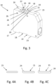
- two connecting profiles 15 are provided, which are arranged on opposite transverse sides 16, 17 of the Connection housings 10 are arranged so that one of the two connecting profiles 15 is attached to an upper side of the connection arrangement 100 and the other of the two connecting profiles 15 is attached to an underside of the connection arrangement 100.
- the two connecting profiles 15 are arranged on the connection housings 10 such that they run parallel to one another.
- the two connecting profiles 15 are permanently attached to the connection housings 10 using a laser transmission welding process.
- the connecting profiles 15 are made of a laser-transparent material, and the welding surfaces 18 are made, at least in some areas, of a laser-absorbing material.
- the material of the connecting profiles 15 is transparent to the laser wavelength used during the welding process. The laser can therefore pass through the material of the connecting profiles 15 almost unhindered. Due to the transparency of the material of the connecting profiles 15, the connecting profiles 15 hardly heat up during the welding process.
- the laser-absorbing material of the welding surface 18 absorbs the energy of the laser beam, causing it to melt.
- the welding surface 18 is delimited by a non-weldable edge region 21.
- the non-weldable edge region 21 is formed by two opposing edge webs. These extend transversely to the longitudinal extent of a welded connecting profile 15.
- the edge region 21 or the edge webs are positioned adjacent to the adjacently arranged connection housings 10.
- the edge region 21 or the edge webs can serve as a support surface for the connecting profiles 15.
- the welding surface 18 is formed in a recess 22 or cutout on an outer surface 23 of the transverse side 16 of the connection housing 10.
- the recess 22 has a rectangular shape and represents a depression in the connection housing 10.
- the recess 22 allows a defined placement of the connecting profiles 15 on the connection housing 10 by inserting the connecting profile 15 into the recess 22.
- the placement of the connecting profiles 15 is carried out in such a way that the connecting profile 15 arranged in the recess 22 is flush with the outer surface 23 of the terminal housing 10, as shown particularly in Fig. 1 and 2 can be seen.
- the connecting profile 15 can have a gripping area 24.
- the gripping area 24 is formed by a bevel of one or both edge areas of the strip-shaped connecting profile 15.
- FIG. 2 and Fig. 4B An embodiment of a connecting profile 15 is shown in which an edge region of the strip-shaped connecting profile 15 is bent, so that a grip region 24 is formed only on one longitudinal side of the connecting profile 15.
- the connecting profile 15 has an L-shaped cross-section.
- FIG. 4C A design of a connecting profile 15 is shown in which the two opposite edge regions of the strip-shaped connecting profile 15 are beveled, so that a gripping region 24 is formed on each of the two longitudinal sides of the connecting profile 15.
- the connecting profile 15 has a U-shaped cross-section.
- Connection arrangement 100 Junction box 10 long side 11 soldering leg 12 Plug-in attachment 13 Conductor insertion opening 14 Connection profile 15 short side 16 short side 17 Welding surface 18 melt rib 19 Enamel depression 20 peripheral area 21 recess 22 exterior surface 23 Grip area 24 Leadership Dome 25 Guide opening 26
Landscapes
- Physics & Mathematics (AREA)
- Optics & Photonics (AREA)
- Engineering & Computer Science (AREA)
- Manufacturing & Machinery (AREA)
- Connection Of Plates (AREA)
- Connector Housings Or Holding Contact Members (AREA)
- Connections Arranged To Contact A Plurality Of Conductors (AREA)
- Connections Effected By Soldering, Adhesion, Or Permanent Deformation (AREA)
Description
- Die Erfindung betrifft eine elektrische Anschlussanordnung, welche mindestens zwei nebeneinander angeordnete Anschlussgehäusen und mindestens ein streifenförmiges Verbindungsprofil zum unlösbaren Verbinden der nebeneinander angeordneten Anschlussgehäuse aufweist, wobei das Verbindungsprofil die nebeneinander angeordneten Anschlussgehäuse überspannt und das Verbindungsprofil mittels eines Laserschweißverfahrens an den nebeneinander angeordneten Anschlussgehäusen unlösbar befestigt ist.
- Es ist bekannt, eine elektrische Anschlussanordnung aus mehreren nebeneinander angeordneten Anschlussgehäusen auszubilden. Innerhalb der Anschlussgehäuse können unterschiedliche Arten von Anschlusselementen angeordnet sein, mittels welchen Leiter bzw. Kabel elektrisch angeschlossen werden können. Die Anschlusselemente können beispielsweise als Federkraftklemmanschluss, Schraubanschluss oder Steckanschluss ausgebildet sein. Die Anschlussgehäuse können beispielsweise in Form eines Steckergehäuses oder eines Leiterplattenanschlussgehäuses ausgebildet sein.
- Die Anschlussgehäuse können scheibenförmig ausgebildet sein, damit diese aneinander angereiht werden können. Zum Verbinden der Anschlussgehäuse miteinander ist es bekannt, dass an der Außenfläche der Anschlussgehäuse Zapfen ausgebildet sind, welche in an den benachbart angeordneten Anschlussgehäusen ausgebildeten Öffnungen eingreifen. Die Anschlussgehäuse können dadurch durch ein Zusammenstecken miteinander lösbar verbunden werden. Diese Art der Verbindung der Anschlussgehäuse weist jedoch nur eine geringe mechanische Stabilität und Festigkeit auf, so dass es leicht zu einem ungewollten Lösen der Anschlussgehäuse voneinander kommen kann.
- Aus der
WO 2017/019605 A1 ist eine Anschlussanordnung bekannt, bei welcher mehrere Anschlussgehäuse nebeneinander in einem Rahmen angeordnet werden können, wobei die Befestigung der Anschlussgehäuse an dem Rahmen mittels eines Laserschweißverfahrens erfolgen kann. - Die
US 2009/035997 A1 offenbart eine Anschlussanordnung, bei welcher mehrere nebeneinander angeordnete Anschlussgehäuse in einem Gehäuse positioniert und von dem Gehäuse umschlossen sind. - Die
US 2016/020546 A1 offenbart eine elektrische Anschlussanordnung nach dem Oberbegriff des Anspruchs 1. - Der Erfindung liegt daher die Aufgabe zu Grunde, eine elektrische Anschlussanordnung zur Verfügung zu stellen, bei welcher die mechanische Festigkeit der Verbindung zwischen nebeneinander angeordneten Anschlussgehäusen verbessert ist.
- Diese Aufgabe wird erfindungsgemäß mit den Merkmalen des unabhängigen Anspruchs gelöst. Zweckmäßige Ausgestaltungen und vorteilhafte Weiterbildungen der Erfindung sind in den Unteransprüchen angegeben.
- Die elektrische Anschlussanordnung gemäß der Erfindung zeichnet sich dadurch aus, dass das Verbindungsprofil aus einem lasertransparenten Material ausgebildet ist.
- Erfindungsgemäß ist es nunmehr vorgesehen, ein als zusätzliches Bauteil ausgebildetes Verbindungsprofil einzusetzen, welches die nebeneinander angeordneten Anschlussgehäuse fest miteinander verbindet, so dass diese nicht mehr voneinander trennbar sind. Das Verbindungsprofil ermöglicht damit eine sehr hohe mechanische Festigkeit aufweisende Verbindung der Anschlussgehäuse miteinander. Das Verbindungsprofil ist streifenförmig ausgebildet, so dass dieses sich flächig, entlang der nebeneinander angeordneten Anschlussgehäuse erstrecken kann. Das Verbindungsprofil überspannt die Anschlussgehäuse derart, dass sich das Verbindungsprofil entlang einer Außenfläche der Anschlussgehäuse erstreckt. Das Verbindungsprofil liegt damit außen an den Anschlussgehäusen an. Durch die streifenförmige Ausgestaltung benötigt das Verbindungsprofil nur sehr wenig Bauraum. Das Verbindungsprofil ist unlösbar an den Anschlussgehäusen befestigt. Durch die unlösbare Befestigung kann das Verbindungsprofil eine besonders hohe Biegesteifigkeit für die Anschlussanordnung erreichen, so dass ein Auseinanderbrechen der Anschlussanordnung insbesondere bei einer Beanspruchung auf Durchbiegung verhindert werden kann. Die unlösbare Verbindung ist dadurch ausgebildet, dass das Verbindungsprofil mittels eines Laserschweißverfahrens an den nebeneinander angeordneten Anschlussgehäusen befestigt ist. Das Verbindungsprofil ist damit über eine Schweißverbindung an den Anschlussgehäusen befestigt. Gegenüber eine Klebverbindung kann die Schweißverbindung auch große Scherkräfte aufnehmen, so dass eine besonders sichere Verbindung der Anschlussgehäuse mittels des angeschweißten Verbindungsprofils erreicht werden kann. Das Laserschweißverfahren ermöglicht ein schnelles Schweißen auf kleinem Bauraum mit einem möglichst geringen Verzug. Das Verbindungsprofil ist vorzugsweise mittels eines Laserdurchstrahlschweißverfahrens an die Anschlussgehäuse angeschweißt.
- Bevorzugt ist es vorgesehen, dass die Anschlussanordnung zwei oder auch mehr solcher Verbindungsprofile aufweist. Sind zwei solcher Verbindungsprofile vorgesehen, so sind diese Verbindungsprofile vorzugsweise gegenüberliegend an den nebeneinander angeordneten Anschlussgehäusen angeordnet sind. Durch eine unlösbare Verbindung zweier solcher Verbindungsprofile an den aneinandergereiht angeordneten Anschlussgehäusen kann die mechanische Festigkeit der Anschlussanordnung weiter verbessert werden und insbesondere auch die Biegesteifigkeit der Anschlussanordnung kann wesentlich erhöht werden.
- Das Verbindungsprofil ist bevorzugt an einer Querseite der Anschlussgehäuse angeordnet. Die Anschlussgehäuse sind vorzugsweise scheibenartig ausgebildet und liegen mit ihrer Längsseite aneinander an. Das Verbindungsprofil kann dann die Anschlussgehäuse entlang einer ihrer Querseiten überspannen. Sind zwei Verbindungsprofile vorgesehen, so erstrecken sich die beiden Verbindungsprofile vorzugsweise jeweils entlang sich gegenüberliegenden Querseiten der Anschlussgehäuse.
- Um eine genaue, besonders bedarfsgerechte Positionierung des Verbindungsprofils an den Anschlussgehäusen erreichen zu können, weisen die Anschlussgehäuse vorzugsweise eine definierte Anschweißfläche zur Aufnahme des Verbindungsprofils auf. Die Anschweißfläche ist vorzugsweise an einer Außenfläche, insbesondere an einer Außenfläche einer Querseite der Anschlussgehäuse ausgebildet. Durch die definierte Anschweißfläche ist die Montage des Verbindungsprofils an den Anschlussgehäusen wesentlich vereinfacht und Fehlmontagen können verhindert werden. Zudem ermöglicht die definierte und damit vorher festgelegte Anschweißfläche eine besonders sichere und stabile Befestigung des Verbindungsprofils an den Anschlussgehäusen. Sind zwei oder mehr Verbindungsprofile an den Anschlussgehäusen zu befestigen, so erhöht sich entsprechend auch die Anzahl der definierten Anschweißflächen pro Anschlussgehäuse.
- Die Anschweißfläche zeichnet sich vorzugsweise durch ein besonders gutes Schmelzverhalten auf.
- Bevorzugt ist die Anschweißfläche zumindest bereichsweise aus einem laserabsorbierenden Material ausgebildet. Durch die Ausbildung der Anschweißfläche zumindest bereichsweise aus einem laserabsorbierenden Material kann die Anschweißfläche die Energie des Laserstrahls beim Schweißvorgang gezielt aufnehmen, um ein gutes Schmelzverhalten im Bereich der Anschweißfläche zu erreichen. Beispielsweise kann der Anschweißfläche Rußpartikel beigemischt sein, um ein hohes Laserabsorbtionsverhalten der Anschweißfläche erreichen zu können.
- Um definierte Schweißbereiche innerhalb der Anschweißfläche erreichen zu können, weist die Anschweißfläche erfindungsgemäß mindestens eine Schmelzrippe und angrenzend zu der Schmelzrippe Schmelzvertiefungen auf. Die Schmelzrippe kann gezielt Material zum Schmelzen während des Laserschweißverfahrens zur Verfügung stellen. Die Schmelzrippen sind vorzugsweise in Form von Erhebungen ausgebildet, welche über die Schmelzvertiefungen hinausragen. Das aufgeschmolzene Material der Schmelzrippe kann während des Schweißvorgangs kontrolliert in die angrenzenden Schmelzvertiefungen fließen, so dass sich das aufgeschmolzene Material gleichmäßig im Bereich der Anschweißfläche verteilen kann und gleichzeitig ein Austreten des aufgeschmolzenen Materials aus der Anschweißfläche verhindert werden kann. Vorzugsweise sind zwei oder mehr Schmelzrippen im Bereich einer Anschweißfläche vorgesehen. Schmelzvertiefungen und Schmelzrippen sind dann vorzugsweise alternierend angeordnet.
- Um ein Austreten des aufgeschmolzenen Materials aus der Anschweißfläche beim Befestigen des Verbindungsprofils an den Anschlussgehäusen verhindern zu können, ist die Anschweißfläche vorzugsweise durch einen nicht schweißbaren Randbereich begrenzt. Der Randbereich kann eine Art Umrandung der Anschweißfläche ausbilden, welche die Anschweißfläche teilweise oder vollständig umschließt. Der Randbereich kann auch eine Art Anschlagsfläche für das an den Anschlussgehäusen befestigte Verbindungsprofil ausbilden, so dass das Verbindungsprofil im befestigten Zustand auf diesem Randbereich definiert aufliegen kann.
- Weiter kann es bevorzugt vorgesehen sein, dass die Anschweißfläche in einer an einer Außenfläche des Anschlussgehäuses ausgebildeten Ausnehmung ausgebildet ist. Durch die Ausnehmung ist eine definierte Ablage des Verbindungsprofils an dem Anschlussgehäuse möglich. Die Ablage des Verbindungsprofils kann dabei derart erfolgen, dass das in der Ausnehmung angeordnete Verbindungsprofil bündig mit der Außenfläche des Anschlussgehäuses abschließt, so dass kein Überstand durch das Verbindungsprofil ausgebildet ist. Bei zwei oder mehr Verbindungsprofilen kann für jedes Verbindungsprofil eine derartige Ausnehmung an einer Außenfläche der Anschlussgehäuse ausgebildet sein.
- Das Verbindungsprofil ist erfindungsgemäß aus einem lasertransparenten Material ausgebildet. Die Energie des Laserstrahls kann dann durch das Material des Verbindungsprofils hindurchgehen und direkt auf die Anschweißfläche geführt werden. Durch die Ausbildung des Verbindungsprofils aus einem lasertransparenten Material wird ein Aufschmelzen des Verbindungsprofils während der Montage des Verbindungsprofils an den Anschlussgehäusen verhindert, so dass das Verbindungsprofil im Wesentlichen formstabil bleiben kann.
- Um die Handhabung der Anschlussanordnung verbessern zu können, kann das Verbindungsprofil einen Griffbereich aufweisen, so dass die Anschlussanordnung über den Griffbereich des Verbindungsprofils gegriffen werden kann. Die Ausbildung des Griffbereichs kann durch eine Abkantung eines oder beider Randbereiche des streifenförmigen Verbindungsprofils ausgebildet sein. Das Verbindungsprofil kann dann einen U-förmig oder L-förmig ausgebildeten Querschnitt aufweisen. Der Griffbereich kann aber auch durch eine andersartige Profilierung des Verbindungsprofils ausgebildet sein.
- Um bei der Montage eine Vorjustierung der nebeneinander anzuordnenden Anschlussgehäuse erreichen zu können, bevor die Befestigung mittels des Verbindungsprofils erfolgen kann, können die nebeneinander angeordneten Anschlussgehäuse Führungsdome und dazu korrespondierende Führungsöffnungen aufweisen, so dass die nebeneinander angeordneten Anschlussgehäuse mittels Führungsdomen und Führungsöffnungen miteinander verbunden werden können. Die Führungsdome und Führungsöffnungen sind vorzugsweise an den Längsseiten der Anschlussgehäuse ausgebildet, über welche die nebeneinander angeordneten Anschlussgehäuse im montierten Zustand flächig aneinander anliegen. Die in die Führungsöffnungen eingreifenden Führungsdome können zudem eine Torsion und eine Verschiebung der Anschlussgehäuse zueinander verhindern.
- Nachfolgend wird die Erfindung unter Bezugnahme auf die anliegenden Zeichnungen anhand bevorzugter Ausführungsformen näher erläutert.
- Es zeigen
- Fig. 1
- eine schematische Darstellung einer elektrischen Anschlussanordnung gemäß der Erfindung,
- Fig. 2
- eine schematische Darstellung einer weiteren elektrischen Anschlussanordnung gemäß der Erfindung,
- Fig. 3
- eine schematische Darstellung eines Anschlussgehäuse einer wie in
Fig. 1 und Fig. 2 gezeigten Anschlussanordnung, und - Fig. 4A - 4C
- eine schematische Darstellung von Verbindungsprofilen mit unterschiedlichen Querschnittsformen.
-
Fig. 1 und 2 zeigen jeweils eine elektrische Anschlussanordnung 100 mit mehreren, hier jeweils fünf, nebeneinander angeordneten Anschlussgehäusen 10, so dass diese Anschlussgehäuse 10 aneinandergereiht angeordnet sind. Die Anschlussgehäuse 10 sind scheibenförmig ausgebildet und liegen mit ihren Längsseiten 11 jeweils flächig an den benachbart angeordneten Anschlussgehäusen 10 an. - Die Anschlussgehäuse 10 können unterschiedlich ausgebildete Anschlusssysteme beinhalten. Bei der in
Fig. 1 gezeigten Ausgestaltung weisen die Anschlussgehäuse 10 ein Leiterplattenanschlusssystem auf, so dass die Anschlussgehäuse 10 über Lötbeine 12 an einer hier nicht gezeigten Leiterplatte elektrisch kontaktierend angeordnet werden können. Bei der inFig. 2 gezeigten Ausgestaltung weisen die Anschlussgehäuse 10 ein Steckersystem mit einem Steckansatz 13 auf. Alle diese Anschlussgehäuse 10 weisen eine Leitereinführöffnung 14 auf, über welche ein Leiter bzw. ein Kabel in das Anschlussgehäuse 10 eingeführt werden kann, um den Leiter bzw. das Kabel in dem Innenraum des Anschlussgehäuses 10 beispielsweise mittels eines Federkraftklemmsystems elektrisch anschließen zu können. - Die in einer Reihe nebeneinander angeordneten Anschlussgehäuse 10 sind mittels eines streifenförmig ausgebildeten Verbindungsprofils 15 unlösbar miteinander verbunden. Das Verbindungsprofil 15 ist aus einem Kunststoffmaterial, insbesondere einem thermoplastischen Kunststoffmaterial, wie beispielsweise Polyamid oder Polypropylen, ausgebildet. Das Verbindungsprofil 15 ist derart an den Anschlussgehäusen 10 angeordnet, dass es diese überspannt, indem sich das Verbindungsprofil 15 entlang der Länge der Anschlussanordnung 100 erstreckt. Das Verbindungsprofil 15 ist als ein zusätzliches Bauteil ausgebildet, welches an den Anschlussgehäusen 10 mittels einer Laserschweißverbindung unlösbar verbunden ist.
- Bei der in
Fig. 1 und 2 gezeigten Ausgestaltung sind zwei Verbindungsprofile 15 vorgesehen, welche an sich gegenüberliegenden Querseiten 16, 17 der Anschlussgehäuse 10 angeordnet sind, so dass eines der beiden Verbindungsprofile 15 an einer Oberseite der Anschlussanordnung 100 und das andere der beiden Verbindungsprofile 15 an einer Unterseite der Anschlussanordnung 100 befestigt ist. Die beiden Verbindungsprofile 15 sind dabei derart an den Anschlussgehäusen 10 angeordnet, dass sie parallel zueinander verlaufen. - Um eine gezielte, positionsgenaue Befestigung der Verbindungsprofile 15 an den Anschlussgehäusen 10 erreichen zu können, ist an den Anschlussgehäusen 10 für jedes Verbindungsprofil 15 eine definierte Anschweißfläche 18 ausgebildet, auf welche die Verbindungsprofile 15 bei der Montage aufgelegt und dort angeschweißt werden.
- Die beiden Verbindungsprofile 15 sind mittels eines Laserdurchstrahlschweißverfahrens unlösbar an den Anschlussgehäusen 10 befestigt. Dafür sind die Verbindungsprofile 15 aus einem lasertransparenten Material ausgebildet und die Anschweißflächen 18 sind zumindest bereichsweise aus einem laserabsorbierenden Material ausgebildet. Das Material der Verbindungsprofile 15 ist für die verwendete Laserwellenlänge beim Schweißvorgang transparent. Durch das Material der Verbindungsprofile 15 kann somit der Laser nahezu ungehindert durchstrahlen. Aufgrund der Transparenz des Materials der Verbindungsprofile 15 kommt es kaum zu einer Erwärmung der Verbindungsprofile 15 während des Schweißvorgangs. Das laserabsorbierende Material der Anschweißfläche 18 absorbiert hingegen die Strahlung des Laserstrahls. Das laserabsorbierende Material der Anschweißfläche 18 nimmt die Energie des Laserstrahls auf, so dass dieses anfängt zu schmelzen. Die beim Schmelzen entstehende Wärme wird durch Wärmeleitung an das auf der jeweiligen Anschweißfläche 18 aufliegende Verbindungsprofil 15 weitergegeben. Dadurch kommt es zu einem Anschmelzen der Verbindungsprofile 15 im Auflagebereich der Verbindungsprofile 15 auf der jeweiligen Anschweißfläche 18, wobei die Schmelze der Anschweißfläche 18 mit dem angeschmolzenen Randbereich des Verbindungsprofils 15 eine stoffschlüssige Verbindung ausbildet, wodurch eine Schweißnaht ausgebildet wird.
- Die Anschweißfläche 18 weist Schmelzrippen 19 und benachbart zu den Schmelzrippen 19 ausgebildete Schmelzvertiefungen 20 auf. Die Schmelzrippen 19 stellen definiertes Schmelzmaterial zur Verfügung, welches beim Aufschmelzen in die Schmelzvertiefungen 20 kontrolliert fließen kann, so dass im Bereich der Anschweißfläche eine kontrollierte, definierte Schmelzfläche zum stoffschlüssigen Verbinden mit dem Verbindungsprofil 15 ausgebildet werden kann. Insbesondere die Schmelzrippen 19 sind aus einem laserabsorbierenden Material ausgebildet. Die Schmelzrippen 19 überragen die Schmelzvertiefungen 20. Schmelzrippen 19 und Schmelzvertiefungen 20 sind alternierend angeordnet, wobei bei der hier gezeigten Ausgestaltung zwei Schmelzrippen 19 und drei Schmelzvertiefungen 20 vorgesehen sind.
- Begrenzt ist die Anschweißfläche 18 durch einen nicht schweißbaren Randbereich 21. Bei der hier gezeigten Ausgestaltung ist der nicht schweißbare Randbereich 21 durch zwei sich gegenüberliegende Randstege ausgebildet. Diese verlaufen quer zu der Längserstreckung eines angeschweißten Verbindungsprofils 15. Der Randbereich 21 bzw. die Randstege sind angrenzend zu den benachbart angeordneten Anschlussgehäusen 10 positioniert. Der Randbereich 21 bzw. die Randstege können als Auflagefläche für die Verbindungsprofile 15 dienen.
- Die Anschweißfläche 18 ist jeweils in einer Ausnehmung 22 bzw. Aussparung an einer Außenfläche 23 der Querseite 16 der Anschlussgehäuse 10 ausgebildet. Die Ausnehmung 22 weist eine rechteckige Form auf und stellt eine Vertiefung in dem Anschlussgehäuse 10 dar. Durch die Ausnehmung 22 ist eine definierte Ablage der Verbindungsprofile 15 an dem Anschlussgehäuse 10 möglich, indem das Verbindungsprofil 15 in die Ausnehmung 22 eingelegt wird. Die Ablage der Verbindungsprofile 15 erfolgt derart, dass das in der Ausnehmung 22 angeordnete Verbindungsprofil 15 bündig mit der Außenfläche 23 des Anschlussgehäuses 10 abschließt, wie insbesondere in
Fig. 1 und 2 zu erkennen ist. - Zum besseren Greifen der Anschlussanordnung 100 kann das Verbindungsprofil 15 einen Griffbereich 24 aufweisen. Die Ausbildung des Griffbereichs 24 ist bei den hier gezeigten Ausgestaltungen durch eine Abkantung eines oder beider Randbereiche des streifenförmigen Verbindungsprofils 15 ausgebildet.
- In
Fig. 2 undFig. 4B ist eine Ausgestaltung eines Verbindungsprofils 15 gezeigt, bei welcher ein Randbereich des streifenförmigen Verbindungsprofils 15 abgekantet ist, so dass nur an einer Längsseite des Verbindungsprofils 15 ein Griffbereich 24 ausgebildet ist. Bei dieser Ausgestaltung weist das Verbindungsprofil 15 einen L-förmigen Querschnitt auf. - In
Fig. 4C ist eine Ausgestaltung eines Verbindungsprofils 15 gezeigt, bei welcher die beiden sich gegenüberliegenden Randbereiche des streifenförmigen Verbindungsprofils 15 abgekantet sind, so dass an beiden Längsseiten des Verbindungsprofils 15 jeweils ein Griffbereich 24 ausgebildet ist. Bei dieser Ausgestaltung weist das Verbindungsprofil 15 einen U-förmigen Querschnitt auf. - Bei der in
Fig. 1 undFig. 4A gezeigten Ausgestaltung eines Verbindungsprofils 15 ist kein Griffbereich ausgebildet. - Für eine Vorjustierung bzw. Vormontage der Anschlussgehäuse 10, bevor die Befestigung mit dem Verbindungsprofil 15 erfolgt, sind an den Längsseiten 15 der Anschlussgehäuse 10 Führungsdome 25 und Führungsöffnungen 26 ausgebildet, in welche die Führungsdome 25 eingreifen können. In die Führungsöffnungen 26 eines Anschlussgehäuses 10 können damit die Führungsdome 25 eines benachbart angeordneten Anschlussgehäuses 10 eingreifen.
-
Anschlussanordnung 100 Anschlussgehäuse 10 Längsseite 11 Lötbein 12 Steckansatz 13 Leitereinführöffnung 14 Verbindungsprofil 15 Querseite 16 Querseite 17 Anschweißfläche 18 Schmelzrippe 19 Schmelzvertiefung 20 Randbereich 21 Ausnehmung 22 Außenfläche 23 Griffbereich 24 Führungsdom 25 Führungsöffnung 26
Claims (7)
- Elektrische Anschlussanordnung (100), mit mindestens zwei nebeneinander angeordneten Anschlussgehäusen (10) und mit mindestens einem streifenförmigen Verbindungsprofil (15) zum unlösbaren Verbinden der nebeneinander angeordneten Anschlussgehäuse (10), wobei das Verbindungsprofil (15) die nebeneinander angeordneten Anschlussgehäuse (10) überspannt und das Verbindungsprofil (15) mittels eines Laserschweißverfahrens an den nebeneinander angeordneten Anschlussgehäusen (10) unlösbar befestigt ist, wobei das Verbindungsprofil (15) aus einem lasertransparenten Material ausgebildet ist und wobei die Anschlussgehäuse (10) eine definierte Anschweißfläche (18) zur Aufnahme des Verbindungsprofils (15) aufweisen, dadurch gekennzeichnet, dass die Anschweißfläche (18) mindestens eine Schmelzrippe (19) und angrenzend zu der Schmelzrippe (19) Schmelzvertiefungen (20) aufweist.
- Elektrische Anschlussanordnung (100) nach Anspruch 1, dadurch gekennzeichnet, dass das Verbindungsprofil (15) an einer Querseite (16, 17) der Anschlussgehäuse (10) befestigt ist.
- Elektrische Anschlussanordnung (100) nach Anspruch 1 oder 2, dadurch gekennzeichnet, dass die Anschweißfläche (18) zumindest bereichsweise aus einem laserabsorbierenden Material ausgebildet ist.
- Elektrische Anschlussanordnung (100) nach einem der Ansprüche 1 bis 3, dadurch gekennzeichnet, dass die Anschweißfläche (18) durch einen nicht schweißbaren Randbereich (21) begrenzt ist.
- Elektrische Anschlussanordnung (100) nach einem der Ansprüche 1 bis 4, dadurch gekennzeichnet, dass die Anschweißfläche (18) in einer an einer Außenfläche (23) der Anschlussgehäuse (10) ausgebildeten Ausnehmung (22) ausgebildet ist.
- Elektrische Anschlussanordnung (100) nach einem der Ansprüche 1 bis 5, dadurch gekennzeichnet, dass das Verbindungsprofil (15) einen Griffbereich (24) aufweist.
- Elektrische Anschlussanordnung (100) nach einem der Ansprüche 1 bis 6, dadurch gekennzeichnet, dass die nebeneinander angeordneten Anschlussgehäuse (10) mittels Führungsdomen (25) und Führungsöffnungen (26) miteinander verbunden sind.
Applications Claiming Priority (2)
| Application Number | Priority Date | Filing Date | Title |
|---|---|---|---|
| BE2017/5659A BE1025563B1 (de) | 2017-09-19 | 2017-09-19 | Elektrische anschlussanordnung |
| PCT/EP2018/075306 WO2019057748A1 (de) | 2017-09-19 | 2018-09-19 | Elektrische anschlussanordnung |
Publications (2)
| Publication Number | Publication Date |
|---|---|
| EP3685475A1 EP3685475A1 (de) | 2020-07-29 |
| EP3685475B1 true EP3685475B1 (de) | 2025-07-02 |
Family
ID=59997014
Family Applications (1)
| Application Number | Title | Priority Date | Filing Date |
|---|---|---|---|
| EP18769201.7A Active EP3685475B1 (de) | 2017-09-19 | 2018-09-19 | Elektrische anschlussanordnung |
Country Status (7)
| Country | Link |
|---|---|
| US (1) | US20200203862A1 (de) |
| EP (1) | EP3685475B1 (de) |
| JP (1) | JP7065950B2 (de) |
| CN (2) | CN111133635A (de) |
| BE (1) | BE1025563B1 (de) |
| CA (1) | CA3076245A1 (de) |
| WO (1) | WO2019057748A1 (de) |
Families Citing this family (2)
| Publication number | Priority date | Publication date | Assignee | Title |
|---|---|---|---|---|
| DE102020101026A1 (de) * | 2020-01-17 | 2021-07-22 | Phoenix Contact Gmbh & Co. Kg | Verfahren zur Ausbildung einer Kunststoffkomponente für ein elektrisches Leiteranschlussklemmensystem und mit dem Verfahren hergestellte Kunststoffkomponente |
| BE1028555B1 (de) * | 2020-08-20 | 2022-03-22 | Phoenix Contact Gmbh & Co | Verfahren zum Herstellen einer elektrischen Anschlussanordnung und elektrische Anschlussanordnung |
Citations (1)
| Publication number | Priority date | Publication date | Assignee | Title |
|---|---|---|---|---|
| US20160020546A1 (en) * | 2013-03-11 | 2016-01-21 | Robert Bosch Gmbh | Method for producing a modular electrical connector assembly for a control unit in a motor vehicle |
Family Cites Families (10)
| Publication number | Priority date | Publication date | Assignee | Title |
|---|---|---|---|---|
| JPH05283117A (ja) * | 1992-03-30 | 1993-10-29 | Tokyo Electric Co Ltd | 端子台 |
| US6743057B2 (en) * | 2002-03-27 | 2004-06-01 | Tyco Electronics Corporation | Electrical connector tie bar |
| US7553199B2 (en) * | 2007-07-31 | 2009-06-30 | Phoenix Contact Development & Manufacturing, Inc. | Modular terminal block |
| AU2008202400B2 (en) * | 2007-09-06 | 2011-08-04 | Adc Gmbh | Telecommunications patch panel |
| CN201910503U (zh) * | 2010-06-29 | 2011-07-27 | 深圳麦逊电子有限公司 | 双密压接式连接器 |
| CN202034605U (zh) * | 2011-04-22 | 2011-11-09 | 何胜强 | 组合开关插座 |
| CN203415753U (zh) * | 2013-07-24 | 2014-01-29 | 上海莫仕连接器有限公司 | 电连接器 |
| JP6232970B2 (ja) | 2013-11-25 | 2017-11-22 | 日本精工株式会社 | 締結ボルトの固定構造、電気接続端子台及び電動パワーステアリング装置、並びに締結ボルトの固定構造製造方法 |
| US9698402B2 (en) * | 2014-03-13 | 2017-07-04 | Ford Global Technologies, Llc | Method of welding a bus bar to battery cell terminals |
| US10249978B2 (en) * | 2015-07-29 | 2019-04-02 | Molex, Llc | Modular connector with carrier having an aperture formed on cross member |
-
2017
- 2017-09-19 BE BE2017/5659A patent/BE1025563B1/de not_active IP Right Cessation
-
2018
- 2018-09-19 WO PCT/EP2018/075306 patent/WO2019057748A1/de not_active Ceased
- 2018-09-19 JP JP2020516432A patent/JP7065950B2/ja not_active Expired - Fee Related
- 2018-09-19 EP EP18769201.7A patent/EP3685475B1/de active Active
- 2018-09-19 CA CA3076245A patent/CA3076245A1/en not_active Abandoned
- 2018-09-19 US US16/640,083 patent/US20200203862A1/en not_active Abandoned
- 2018-09-19 CN CN201880060783.9A patent/CN111133635A/zh active Pending
- 2018-09-19 CN CN202210590109.XA patent/CN114883875A/zh active Pending
Patent Citations (1)
| Publication number | Priority date | Publication date | Assignee | Title |
|---|---|---|---|---|
| US20160020546A1 (en) * | 2013-03-11 | 2016-01-21 | Robert Bosch Gmbh | Method for producing a modular electrical connector assembly for a control unit in a motor vehicle |
Also Published As
| Publication number | Publication date |
|---|---|
| BE1025563A1 (de) | 2019-04-12 |
| EP3685475A1 (de) | 2020-07-29 |
| WO2019057748A1 (de) | 2019-03-28 |
| CN111133635A (zh) | 2020-05-08 |
| US20200203862A1 (en) | 2020-06-25 |
| JP7065950B2 (ja) | 2022-05-12 |
| JP2020535594A (ja) | 2020-12-03 |
| CA3076245A1 (en) | 2019-03-28 |
| BE1025563B1 (de) | 2019-04-19 |
| CN114883875A (zh) | 2022-08-09 |
Similar Documents
| Publication | Publication Date | Title |
|---|---|---|
| EP1777720B1 (de) | Elektrisches Bauteil, insbesondere Relaisfassung, mit Federklemmen und Verfahren zu seiner Herstellung | |
| EP0896898B1 (de) | Träger, vorzugsweise für Heckleuchten von Kraftfahrzeugen | |
| DE19947137B4 (de) | Elektrische Schmelzsicherung für stärkere Ströme in einem Kraftfahrzeug | |
| DE112011101397T5 (de) | Verbindungsstruktur für ein Verdrahtungselement | |
| DE19634309A1 (de) | Leitungshalter mit Aufnahmebereich zum beiderseitigen Aufstecken auf einen Gewindebolzen | |
| DE4413756C1 (de) | Gehäuse für einen Steckverbinder | |
| EP4235976B1 (de) | Steckverbinder umfassend eine schutzleiterbrücke | |
| EP3224907B1 (de) | Steckverbinder für flexible leiterfolien | |
| DE202014010345U1 (de) | Anschlussleiste für ein Elektronikgerät | |
| DE102020212592A1 (de) | Separatorplatte für einen Brennstoffzellenstapel, Brennstoffzellenstapel sowie Verfahren zur Herstellung einer Separatorplatte | |
| WO2021028077A1 (de) | Buchse xlr 8+2 pcb | |
| DE4431274C2 (de) | Verfahren zum Herstellen eines Elektro-Installationsgerätes sowie Elektro-Installationsgerät | |
| BE1025563B1 (de) | Elektrische anschlussanordnung | |
| EP3218240B1 (de) | Wandanordnung für ein fahrzeug | |
| EP3890102B1 (de) | Vorrichtung mit einem rahmen, der aufnahmen für die stirnseitigen endabschnitte von bezüglich ihrer längsachse parallel ausgerichteten batteriezellen aufweist | |
| DE102011102624B4 (de) | Halteelement und Halteanordnung zum Halten einer Sicherung sowie Sicherungssystem | |
| EP3776744B1 (de) | Leiterplattenanordnung | |
| DE102017121650A1 (de) | Elektrische Anschlussanordnung | |
| DE102020133968A1 (de) | Elektrische anschlussanordnung mit vergrössertem kontaktbereich | |
| DE102016107055B4 (de) | Potentialausgleichsklemme | |
| DE102015121832B4 (de) | Steckverbinder zur elektrischen Direktkontaktierung und Steckverbindung | |
| DE102018133135A1 (de) | Halterahmen für einen Steckverbinder | |
| EP3600848B1 (de) | Verfahren zur verbindung von drei bauteilen und verbindbares system zur durchführung des verfahrens | |
| EP1035617B1 (de) | Verbindungselement | |
| DE19749145A1 (de) | Elektrischer Anschlußbehälter |
Legal Events
| Date | Code | Title | Description |
|---|---|---|---|
| STAA | Information on the status of an ep patent application or granted ep patent |
Free format text: STATUS: UNKNOWN |
|
| STAA | Information on the status of an ep patent application or granted ep patent |
Free format text: STATUS: THE INTERNATIONAL PUBLICATION HAS BEEN MADE |
|
| PUAI | Public reference made under article 153(3) epc to a published international application that has entered the european phase |
Free format text: ORIGINAL CODE: 0009012 |
|
| STAA | Information on the status of an ep patent application or granted ep patent |
Free format text: STATUS: REQUEST FOR EXAMINATION WAS MADE |
|
| 17P | Request for examination filed |
Effective date: 20200327 |
|
| AK | Designated contracting states |
Kind code of ref document: A1 Designated state(s): AL AT BE BG CH CY CZ DE DK EE ES FI FR GB GR HR HU IE IS IT LI LT LU LV MC MK MT NL NO PL PT RO RS SE SI SK SM TR |
|
| AX | Request for extension of the european patent |
Extension state: BA ME |
|
| DAV | Request for validation of the european patent (deleted) | ||
| DAX | Request for extension of the european patent (deleted) | ||
| STAA | Information on the status of an ep patent application or granted ep patent |
Free format text: STATUS: EXAMINATION IS IN PROGRESS |
|
| 17Q | First examination report despatched |
Effective date: 20211001 |
|
| P01 | Opt-out of the competence of the unified patent court (upc) registered |
Effective date: 20230512 |
|
| GRAP | Despatch of communication of intention to grant a patent |
Free format text: ORIGINAL CODE: EPIDOSNIGR1 |
|
| STAA | Information on the status of an ep patent application or granted ep patent |
Free format text: STATUS: GRANT OF PATENT IS INTENDED |
|
| INTG | Intention to grant announced |
Effective date: 20250207 |
|
| GRAS | Grant fee paid |
Free format text: ORIGINAL CODE: EPIDOSNIGR3 |
|
| GRAA | (expected) grant |
Free format text: ORIGINAL CODE: 0009210 |
|
| STAA | Information on the status of an ep patent application or granted ep patent |
Free format text: STATUS: THE PATENT HAS BEEN GRANTED |
|
| AK | Designated contracting states |
Kind code of ref document: B1 Designated state(s): AL AT BE BG CH CY CZ DE DK EE ES FI FR GB GR HR HU IE IS IT LI LT LU LV MC MK MT NL NO PL PT RO RS SE SI SK SM TR |
|
| REG | Reference to a national code |
Ref country code: GB Ref legal event code: FG4D Free format text: NOT ENGLISH |
|
| REG | Reference to a national code |
Ref country code: CH Ref legal event code: EP |
|
| REG | Reference to a national code |
Ref country code: DE Ref legal event code: R096 Ref document number: 502018015923 Country of ref document: DE |
|
| REG | Reference to a national code |
Ref country code: IE Ref legal event code: FG4D Free format text: LANGUAGE OF EP DOCUMENT: GERMAN |
|
| REG | Reference to a national code |
Ref country code: NL Ref legal event code: MP Effective date: 20250702 |
|
| PG25 | Lapsed in a contracting state [announced via postgrant information from national office to epo] |
Ref country code: PT Free format text: LAPSE BECAUSE OF FAILURE TO SUBMIT A TRANSLATION OF THE DESCRIPTION OR TO PAY THE FEE WITHIN THE PRESCRIBED TIME-LIMIT Effective date: 20251103 |
|
| PG25 | Lapsed in a contracting state [announced via postgrant information from national office to epo] |
Ref country code: NL Free format text: LAPSE BECAUSE OF FAILURE TO SUBMIT A TRANSLATION OF THE DESCRIPTION OR TO PAY THE FEE WITHIN THE PRESCRIBED TIME-LIMIT Effective date: 20250702 |
|
| PG25 | Lapsed in a contracting state [announced via postgrant information from national office to epo] |
Ref country code: IS Free format text: LAPSE BECAUSE OF FAILURE TO SUBMIT A TRANSLATION OF THE DESCRIPTION OR TO PAY THE FEE WITHIN THE PRESCRIBED TIME-LIMIT Effective date: 20251102 |
|
| PGFP | Annual fee paid to national office [announced via postgrant information from national office to epo] |
Ref country code: DE Payment date: 20251126 Year of fee payment: 8 |
|
| PG25 | Lapsed in a contracting state [announced via postgrant information from national office to epo] |
Ref country code: NO Free format text: LAPSE BECAUSE OF FAILURE TO SUBMIT A TRANSLATION OF THE DESCRIPTION OR TO PAY THE FEE WITHIN THE PRESCRIBED TIME-LIMIT Effective date: 20251002 |
|
| REG | Reference to a national code |
Ref country code: LT Ref legal event code: MG9D |
|
| PG25 | Lapsed in a contracting state [announced via postgrant information from national office to epo] |
Ref country code: FI Free format text: LAPSE BECAUSE OF FAILURE TO SUBMIT A TRANSLATION OF THE DESCRIPTION OR TO PAY THE FEE WITHIN THE PRESCRIBED TIME-LIMIT Effective date: 20250702 |
|
| PG25 | Lapsed in a contracting state [announced via postgrant information from national office to epo] |
Ref country code: HR Free format text: LAPSE BECAUSE OF FAILURE TO SUBMIT A TRANSLATION OF THE DESCRIPTION OR TO PAY THE FEE WITHIN THE PRESCRIBED TIME-LIMIT Effective date: 20250702 |
|
| PG25 | Lapsed in a contracting state [announced via postgrant information from national office to epo] |
Ref country code: GR Free format text: LAPSE BECAUSE OF FAILURE TO SUBMIT A TRANSLATION OF THE DESCRIPTION OR TO PAY THE FEE WITHIN THE PRESCRIBED TIME-LIMIT Effective date: 20251003 |
|
| PG25 | Lapsed in a contracting state [announced via postgrant information from national office to epo] |
Ref country code: SE Free format text: LAPSE BECAUSE OF FAILURE TO SUBMIT A TRANSLATION OF THE DESCRIPTION OR TO PAY THE FEE WITHIN THE PRESCRIBED TIME-LIMIT Effective date: 20250702 Ref country code: CZ Free format text: LAPSE BECAUSE OF FAILURE TO SUBMIT A TRANSLATION OF THE DESCRIPTION OR TO PAY THE FEE WITHIN THE PRESCRIBED TIME-LIMIT Effective date: 20250702 |
|
| PG25 | Lapsed in a contracting state [announced via postgrant information from national office to epo] |
Ref country code: LV Free format text: LAPSE BECAUSE OF FAILURE TO SUBMIT A TRANSLATION OF THE DESCRIPTION OR TO PAY THE FEE WITHIN THE PRESCRIBED TIME-LIMIT Effective date: 20250702 |
|
| PG25 | Lapsed in a contracting state [announced via postgrant information from national office to epo] |
Ref country code: PL Free format text: LAPSE BECAUSE OF FAILURE TO SUBMIT A TRANSLATION OF THE DESCRIPTION OR TO PAY THE FEE WITHIN THE PRESCRIBED TIME-LIMIT Effective date: 20250702 Ref country code: BG Free format text: LAPSE BECAUSE OF FAILURE TO SUBMIT A TRANSLATION OF THE DESCRIPTION OR TO PAY THE FEE WITHIN THE PRESCRIBED TIME-LIMIT Effective date: 20250702 |
|
| PG25 | Lapsed in a contracting state [announced via postgrant information from national office to epo] |
Ref country code: RS Free format text: LAPSE BECAUSE OF FAILURE TO SUBMIT A TRANSLATION OF THE DESCRIPTION OR TO PAY THE FEE WITHIN THE PRESCRIBED TIME-LIMIT Effective date: 20251002 |
|
| PG25 | Lapsed in a contracting state [announced via postgrant information from national office to epo] |
Ref country code: ES Free format text: LAPSE BECAUSE OF FAILURE TO SUBMIT A TRANSLATION OF THE DESCRIPTION OR TO PAY THE FEE WITHIN THE PRESCRIBED TIME-LIMIT Effective date: 20250702 |
|
| PG25 | Lapsed in a contracting state [announced via postgrant information from national office to epo] |
Ref country code: RO Free format text: LAPSE BECAUSE OF FAILURE TO SUBMIT A TRANSLATION OF THE DESCRIPTION OR TO PAY THE FEE WITHIN THE PRESCRIBED TIME-LIMIT Effective date: 20250702 |
|
| PG25 | Lapsed in a contracting state [announced via postgrant information from national office to epo] |
Ref country code: SM Free format text: LAPSE BECAUSE OF FAILURE TO SUBMIT A TRANSLATION OF THE DESCRIPTION OR TO PAY THE FEE WITHIN THE PRESCRIBED TIME-LIMIT Effective date: 20250702 |
|
| PG25 | Lapsed in a contracting state [announced via postgrant information from national office to epo] |
Ref country code: DK Free format text: LAPSE BECAUSE OF FAILURE TO SUBMIT A TRANSLATION OF THE DESCRIPTION OR TO PAY THE FEE WITHIN THE PRESCRIBED TIME-LIMIT Effective date: 20250702 |
|
| PG25 | Lapsed in a contracting state [announced via postgrant information from national office to epo] |
Ref country code: IT Free format text: LAPSE BECAUSE OF FAILURE TO SUBMIT A TRANSLATION OF THE DESCRIPTION OR TO PAY THE FEE WITHIN THE PRESCRIBED TIME-LIMIT Effective date: 20250702 |
|
| PG25 | Lapsed in a contracting state [announced via postgrant information from national office to epo] |
Ref country code: SK Free format text: LAPSE BECAUSE OF FAILURE TO SUBMIT A TRANSLATION OF THE DESCRIPTION OR TO PAY THE FEE WITHIN THE PRESCRIBED TIME-LIMIT Effective date: 20250702 Ref country code: EE Free format text: LAPSE BECAUSE OF FAILURE TO SUBMIT A TRANSLATION OF THE DESCRIPTION OR TO PAY THE FEE WITHIN THE PRESCRIBED TIME-LIMIT Effective date: 20250702 |
|
| REG | Reference to a national code |
Ref country code: CH Ref legal event code: H13 Free format text: ST27 STATUS EVENT CODE: U-0-0-H10-H13 (AS PROVIDED BY THE NATIONAL OFFICE) Effective date: 20260504 |
|
| PLBE | No opposition filed within time limit |
Free format text: ORIGINAL CODE: 0009261 |
|
| STAA | Information on the status of an ep patent application or granted ep patent |
Free format text: STATUS: NO OPPOSITION FILED WITHIN TIME LIMIT |