EP3685708B1 - Kühlschrank - Google Patents
Kühlschrank Download PDFInfo
- Publication number
- EP3685708B1 EP3685708B1 EP20156873.0A EP20156873A EP3685708B1 EP 3685708 B1 EP3685708 B1 EP 3685708B1 EP 20156873 A EP20156873 A EP 20156873A EP 3685708 B1 EP3685708 B1 EP 3685708B1
- Authority
- EP
- European Patent Office
- Prior art keywords
- door
- refrigerator
- sub
- detection device
- display
- Prior art date
- Legal status (The legal status is an assumption and is not a legal conclusion. Google has not performed a legal analysis and makes no representation as to the accuracy of the status listed.)
- Active
Links
Images





















Classifications
-
- F—MECHANICAL ENGINEERING; LIGHTING; HEATING; WEAPONS; BLASTING
- F25—REFRIGERATION OR COOLING; COMBINED HEATING AND REFRIGERATION SYSTEMS; HEAT PUMP SYSTEMS; MANUFACTURE OR STORAGE OF ICE; LIQUEFACTION SOLIDIFICATION OF GASES
- F25D—REFRIGERATORS; COLD ROOMS; ICE-BOXES; COOLING OR FREEZING APPARATUS NOT OTHERWISE PROVIDED FOR
- F25D27/00—Lighting arrangements
- F25D27/005—Lighting arrangements combined with control means
-
- A—HUMAN NECESSITIES
- A47—FURNITURE; DOMESTIC ARTICLES OR APPLIANCES; COFFEE MILLS; SPICE MILLS; SUCTION CLEANERS IN GENERAL
- A47F—SPECIAL FURNITURE, FITTINGS, OR ACCESSORIES FOR SHOPS, STOREHOUSES, BARS, RESTAURANTS OR THE LIKE; PAYING COUNTERS
- A47F3/00—Show cases or show cabinets
- A47F3/04—Show cases or show cabinets air-conditioned, refrigerated
- A47F3/0404—Cases or cabinets of the closed type
- A47F3/0426—Details
- A47F3/0434—Glass or transparent panels
-
- B—PERFORMING OPERATIONS; TRANSPORTING
- B29—WORKING OF PLASTICS; WORKING OF SUBSTANCES IN A PLASTIC STATE IN GENERAL
- B29C—SHAPING OR JOINING OF PLASTICS; SHAPING OF MATERIAL IN A PLASTIC STATE, NOT OTHERWISE PROVIDED FOR; AFTER-TREATMENT OF THE SHAPED PRODUCTS, e.g. REPAIRING
- B29C44/00—Shaping by internal pressure generated in the material, e.g. swelling or foaming ; Producing porous or cellular expanded plastics articles
- B29C44/02—Shaping by internal pressure generated in the material, e.g. swelling or foaming ; Producing porous or cellular expanded plastics articles for articles of definite length, i.e. discrete articles
- B29C44/12—Incorporating or moulding on preformed parts, e.g. inserts or reinforcements
- B29C44/18—Filling preformed cavities
-
- F—MECHANICAL ENGINEERING; LIGHTING; HEATING; WEAPONS; BLASTING
- F21—LIGHTING
- F21V—FUNCTIONAL FEATURES OR DETAILS OF LIGHTING DEVICES OR SYSTEMS THEREOF; STRUCTURAL COMBINATIONS OF LIGHTING DEVICES WITH OTHER ARTICLES, NOT OTHERWISE PROVIDED FOR
- F21V19/00—Fastening of light sources or lamp holders
- F21V19/001—Fastening of light sources or lamp holders the light sources being semiconductors devices, e.g. LEDs
- F21V19/003—Fastening of light source holders, e.g. of circuit boards or substrates holding light sources
-
- F—MECHANICAL ENGINEERING; LIGHTING; HEATING; WEAPONS; BLASTING
- F21—LIGHTING
- F21V—FUNCTIONAL FEATURES OR DETAILS OF LIGHTING DEVICES OR SYSTEMS THEREOF; STRUCTURAL COMBINATIONS OF LIGHTING DEVICES WITH OTHER ARTICLES, NOT OTHERWISE PROVIDED FOR
- F21V23/00—Arrangement of electric circuit elements in or on lighting devices
- F21V23/04—Arrangement of electric circuit elements in or on lighting devices the elements being switches
- F21V23/0442—Arrangement of electric circuit elements in or on lighting devices the elements being switches activated by means of a sensor, e.g. motion or photodetectors
-
- F—MECHANICAL ENGINEERING; LIGHTING; HEATING; WEAPONS; BLASTING
- F21—LIGHTING
- F21V—FUNCTIONAL FEATURES OR DETAILS OF LIGHTING DEVICES OR SYSTEMS THEREOF; STRUCTURAL COMBINATIONS OF LIGHTING DEVICES WITH OTHER ARTICLES, NOT OTHERWISE PROVIDED FOR
- F21V3/00—Globes; Bowls; Cover glasses
-
- F—MECHANICAL ENGINEERING; LIGHTING; HEATING; WEAPONS; BLASTING
- F25—REFRIGERATION OR COOLING; COMBINED HEATING AND REFRIGERATION SYSTEMS; HEAT PUMP SYSTEMS; MANUFACTURE OR STORAGE OF ICE; LIQUEFACTION SOLIDIFICATION OF GASES
- F25D—REFRIGERATORS; COLD ROOMS; ICE-BOXES; COOLING OR FREEZING APPARATUS NOT OTHERWISE PROVIDED FOR
- F25D11/00—Self-contained movable devices, e.g. domestic refrigerators
- F25D11/02—Self-contained movable devices, e.g. domestic refrigerators with cooling compartments at different temperatures
-
- F—MECHANICAL ENGINEERING; LIGHTING; HEATING; WEAPONS; BLASTING
- F25—REFRIGERATION OR COOLING; COMBINED HEATING AND REFRIGERATION SYSTEMS; HEAT PUMP SYSTEMS; MANUFACTURE OR STORAGE OF ICE; LIQUEFACTION SOLIDIFICATION OF GASES
- F25D—REFRIGERATORS; COLD ROOMS; ICE-BOXES; COOLING OR FREEZING APPARATUS NOT OTHERWISE PROVIDED FOR
- F25D23/00—General constructional features
- F25D23/02—Doors; Covers
-
- F—MECHANICAL ENGINEERING; LIGHTING; HEATING; WEAPONS; BLASTING
- F25—REFRIGERATION OR COOLING; COMBINED HEATING AND REFRIGERATION SYSTEMS; HEAT PUMP SYSTEMS; MANUFACTURE OR STORAGE OF ICE; LIQUEFACTION SOLIDIFICATION OF GASES
- F25D—REFRIGERATORS; COLD ROOMS; ICE-BOXES; COOLING OR FREEZING APPARATUS NOT OTHERWISE PROVIDED FOR
- F25D23/00—General constructional features
- F25D23/02—Doors; Covers
- F25D23/028—Details
-
- F—MECHANICAL ENGINEERING; LIGHTING; HEATING; WEAPONS; BLASTING
- F25—REFRIGERATION OR COOLING; COMBINED HEATING AND REFRIGERATION SYSTEMS; HEAT PUMP SYSTEMS; MANUFACTURE OR STORAGE OF ICE; LIQUEFACTION SOLIDIFICATION OF GASES
- F25D—REFRIGERATORS; COLD ROOMS; ICE-BOXES; COOLING OR FREEZING APPARATUS NOT OTHERWISE PROVIDED FOR
- F25D29/00—Arrangement or mounting of control or safety devices
- F25D29/005—Mounting of control devices
-
- G—PHYSICS
- G03—PHOTOGRAPHY; CINEMATOGRAPHY; ANALOGOUS TECHNIQUES USING WAVES OTHER THAN OPTICAL WAVES; ELECTROGRAPHY; HOLOGRAPHY
- G03B—APPARATUS OR ARRANGEMENTS FOR TAKING PHOTOGRAPHS OR FOR PROJECTING OR VIEWING THEM; APPARATUS OR ARRANGEMENTS EMPLOYING ANALOGOUS TECHNIQUES USING WAVES OTHER THAN OPTICAL WAVES; ACCESSORIES THEREFOR
- G03B29/00—Combinations of cameras, projectors or photographic printing apparatus with non-photographic non-optical apparatus, e.g. clocks or weapons; Cameras having the shape of other objects
-
- H—ELECTRICITY
- H05—ELECTRIC TECHNIQUES NOT OTHERWISE PROVIDED FOR
- H05B—ELECTRIC HEATING; ELECTRIC LIGHT SOURCES NOT OTHERWISE PROVIDED FOR; CIRCUIT ARRANGEMENTS FOR ELECTRIC LIGHT SOURCES, IN GENERAL
- H05B47/00—Circuit arrangements for operating light sources in general, i.e. where the type of light source is not relevant
- H05B47/10—Controlling the light source
- H05B47/105—Controlling the light source in response to determined parameters
- H05B47/115—Controlling the light source in response to determined parameters by determining the presence or movement of objects or living beings
-
- H—ELECTRICITY
- H05—ELECTRIC TECHNIQUES NOT OTHERWISE PROVIDED FOR
- H05B—ELECTRIC HEATING; ELECTRIC LIGHT SOURCES NOT OTHERWISE PROVIDED FOR; CIRCUIT ARRANGEMENTS FOR ELECTRIC LIGHT SOURCES, IN GENERAL
- H05B47/00—Circuit arrangements for operating light sources in general, i.e. where the type of light source is not relevant
- H05B47/10—Controlling the light source
- H05B47/16—Controlling the light source by timing means
-
- F—MECHANICAL ENGINEERING; LIGHTING; HEATING; WEAPONS; BLASTING
- F21—LIGHTING
- F21W—INDEXING SCHEME ASSOCIATED WITH SUBCLASSES F21K, F21L, F21S and F21V, RELATING TO USES OR APPLICATIONS OF LIGHTING DEVICES OR SYSTEMS
- F21W2131/00—Use or application of lighting devices or systems not provided for in codes F21W2102/00-F21W2121/00
- F21W2131/30—Lighting for domestic or personal use
- F21W2131/305—Lighting for domestic or personal use for refrigerators
-
- F—MECHANICAL ENGINEERING; LIGHTING; HEATING; WEAPONS; BLASTING
- F21—LIGHTING
- F21Y—INDEXING SCHEME ASSOCIATED WITH SUBCLASSES F21K, F21L, F21S and F21V, RELATING TO THE FORM OR THE KIND OF THE LIGHT SOURCES OR OF THE COLOUR OF THE LIGHT EMITTED
- F21Y2115/00—Light-generating elements of semiconductor light sources
- F21Y2115/10—Light-emitting diodes [LED]
-
- F—MECHANICAL ENGINEERING; LIGHTING; HEATING; WEAPONS; BLASTING
- F25—REFRIGERATION OR COOLING; COMBINED HEATING AND REFRIGERATION SYSTEMS; HEAT PUMP SYSTEMS; MANUFACTURE OR STORAGE OF ICE; LIQUEFACTION SOLIDIFICATION OF GASES
- F25D—REFRIGERATORS; COLD ROOMS; ICE-BOXES; COOLING OR FREEZING APPARATUS NOT OTHERWISE PROVIDED FOR
- F25D2201/00—Insulation
- F25D2201/10—Insulation with respect to heat
- F25D2201/12—Insulation with respect to heat using an insulating packing material
- F25D2201/126—Insulation with respect to heat using an insulating packing material of cellular type
-
- F—MECHANICAL ENGINEERING; LIGHTING; HEATING; WEAPONS; BLASTING
- F25—REFRIGERATION OR COOLING; COMBINED HEATING AND REFRIGERATION SYSTEMS; HEAT PUMP SYSTEMS; MANUFACTURE OR STORAGE OF ICE; LIQUEFACTION SOLIDIFICATION OF GASES
- F25D—REFRIGERATORS; COLD ROOMS; ICE-BOXES; COOLING OR FREEZING APPARATUS NOT OTHERWISE PROVIDED FOR
- F25D2323/00—General constructional features not provided for in other groups of this subclass
- F25D2323/02—Details of doors or covers not otherwise covered
- F25D2323/021—French doors
-
- F—MECHANICAL ENGINEERING; LIGHTING; HEATING; WEAPONS; BLASTING
- F25—REFRIGERATION OR COOLING; COMBINED HEATING AND REFRIGERATION SYSTEMS; HEAT PUMP SYSTEMS; MANUFACTURE OR STORAGE OF ICE; LIQUEFACTION SOLIDIFICATION OF GASES
- F25D—REFRIGERATORS; COLD ROOMS; ICE-BOXES; COOLING OR FREEZING APPARATUS NOT OTHERWISE PROVIDED FOR
- F25D2323/00—General constructional features not provided for in other groups of this subclass
- F25D2323/02—Details of doors or covers not otherwise covered
- F25D2323/023—Door in door constructions
-
- F—MECHANICAL ENGINEERING; LIGHTING; HEATING; WEAPONS; BLASTING
- F25—REFRIGERATION OR COOLING; COMBINED HEATING AND REFRIGERATION SYSTEMS; HEAT PUMP SYSTEMS; MANUFACTURE OR STORAGE OF ICE; LIQUEFACTION SOLIDIFICATION OF GASES
- F25D—REFRIGERATORS; COLD ROOMS; ICE-BOXES; COOLING OR FREEZING APPARATUS NOT OTHERWISE PROVIDED FOR
- F25D2323/00—General constructional features not provided for in other groups of this subclass
- F25D2323/02—Details of doors or covers not otherwise covered
- F25D2323/024—Door hinges
-
- F—MECHANICAL ENGINEERING; LIGHTING; HEATING; WEAPONS; BLASTING
- F25—REFRIGERATION OR COOLING; COMBINED HEATING AND REFRIGERATION SYSTEMS; HEAT PUMP SYSTEMS; MANUFACTURE OR STORAGE OF ICE; LIQUEFACTION SOLIDIFICATION OF GASES
- F25D—REFRIGERATORS; COLD ROOMS; ICE-BOXES; COOLING OR FREEZING APPARATUS NOT OTHERWISE PROVIDED FOR
- F25D2327/00—Lighting arrangements not provided for in other groups of this subclass
-
- F—MECHANICAL ENGINEERING; LIGHTING; HEATING; WEAPONS; BLASTING
- F25—REFRIGERATION OR COOLING; COMBINED HEATING AND REFRIGERATION SYSTEMS; HEAT PUMP SYSTEMS; MANUFACTURE OR STORAGE OF ICE; LIQUEFACTION SOLIDIFICATION OF GASES
- F25D—REFRIGERATORS; COLD ROOMS; ICE-BOXES; COOLING OR FREEZING APPARATUS NOT OTHERWISE PROVIDED FOR
- F25D2400/00—General features of, or devices for refrigerators, cold rooms, ice-boxes, or for cooling or freezing apparatus not covered by any other subclass
- F25D2400/36—Visual displays
-
- F—MECHANICAL ENGINEERING; LIGHTING; HEATING; WEAPONS; BLASTING
- F25—REFRIGERATION OR COOLING; COMBINED HEATING AND REFRIGERATION SYSTEMS; HEAT PUMP SYSTEMS; MANUFACTURE OR STORAGE OF ICE; LIQUEFACTION SOLIDIFICATION OF GASES
- F25D—REFRIGERATORS; COLD ROOMS; ICE-BOXES; COOLING OR FREEZING APPARATUS NOT OTHERWISE PROVIDED FOR
- F25D2400/00—General features of, or devices for refrigerators, cold rooms, ice-boxes, or for cooling or freezing apparatus not covered by any other subclass
- F25D2400/36—Visual displays
- F25D2400/361—Interactive visual displays
-
- F—MECHANICAL ENGINEERING; LIGHTING; HEATING; WEAPONS; BLASTING
- F25—REFRIGERATION OR COOLING; COMBINED HEATING AND REFRIGERATION SYSTEMS; HEAT PUMP SYSTEMS; MANUFACTURE OR STORAGE OF ICE; LIQUEFACTION SOLIDIFICATION OF GASES
- F25D—REFRIGERATORS; COLD ROOMS; ICE-BOXES; COOLING OR FREEZING APPARATUS NOT OTHERWISE PROVIDED FOR
- F25D2700/00—Means for sensing or measuring; Sensors therefor
-
- F—MECHANICAL ENGINEERING; LIGHTING; HEATING; WEAPONS; BLASTING
- F25—REFRIGERATION OR COOLING; COMBINED HEATING AND REFRIGERATION SYSTEMS; HEAT PUMP SYSTEMS; MANUFACTURE OR STORAGE OF ICE; LIQUEFACTION SOLIDIFICATION OF GASES
- F25D—REFRIGERATORS; COLD ROOMS; ICE-BOXES; COOLING OR FREEZING APPARATUS NOT OTHERWISE PROVIDED FOR
- F25D2700/00—Means for sensing or measuring; Sensors therefor
- F25D2700/04—Sensors detecting the presence of a person
-
- Y—GENERAL TAGGING OF NEW TECHNOLOGICAL DEVELOPMENTS; GENERAL TAGGING OF CROSS-SECTIONAL TECHNOLOGIES SPANNING OVER SEVERAL SECTIONS OF THE IPC; TECHNICAL SUBJECTS COVERED BY FORMER USPC CROSS-REFERENCE ART COLLECTIONS [XRACs] AND DIGESTS
- Y02—TECHNOLOGIES OR APPLICATIONS FOR MITIGATION OR ADAPTATION AGAINST CLIMATE CHANGE
- Y02B—CLIMATE CHANGE MITIGATION TECHNOLOGIES RELATED TO BUILDINGS, e.g. HOUSING, HOUSE APPLIANCES OR RELATED END-USER APPLICATIONS
- Y02B20/00—Energy efficient lighting technologies, e.g. halogen lamps or gas discharge lamps
- Y02B20/40—Control techniques providing energy savings, e.g. smart controller or presence detection
Definitions
- a refrigerator is a home appliance which stores food at a low temperature in a storage space formed therein to be shielded by a door.
- the refrigerator is formed to cool an inside of the storage space using cooling air generated through heat exchange with a refrigerant circulated in a refrigeration cycle, and thus to keep the stored food in an optimum state.
- Recent refrigerators become bigger and have multi-functions according to a change in diet and a tendency toward high-quality of a product. And the refrigerators which have various structures and devices for convenience to provide user convenience and also to enable internal spaces to be efficiently used have been released.
- a separate accommodation space which allows access from an outside may be provided at the door of the refrigerator.
- access to the accommodation space may be allowed by opening an auxiliary door or a home-bar door without opening of the entire refrigerator door.
- the present invention is directed to a refrigerator which is able to enhance recognition performance and reliability of an operation for selectively enabling an inside of the refrigerator to be visible through a panel assembly while a refrigerator door is closed.
- the present invention is directed to a refrigerator having a structure which is provided at a refrigerator door, enables a user to see through an inside of the refrigerator even while the refrigerator door is closed, and also insulates the refrigerator door.
- the present invention is directed to a refrigerator which enables an inside of the refrigerator to be seen through while a lighting unit is turned on by a user's operation, and forms a mirror surface while the lighting unit is turned off, thereby forming an exterior of a refrigerator door.
- the present invention is directed to a refrigerator in which a display unit is provided on an opening part of a main door and configured to be shielded by a sub-door to improve the appearance of the refrigerator.
- the present invention is directed to a refrigerator in which a display unit is configured to be selectively detachable inside the refrigerator, so that a suitable display unit may be selectively mounted according to functions and models without any structural change.
- the present invention is directed to a refrigerator which allows to easily check various states thereof without separately operating a display.
- the display unit may be detachably provided in the opening part.
- Display installing protrusions may be formed on the opening part, and display guides in which the installing protrusions are inserted may be formed on both side surfaces of the display unit.
- the installing protrusions may be provided on both side surfaces of the opening part, and the display guides may be opened downward, so that the installing protrusions may be inserted and mounted.
- a door connector connected with a main control part controlling the operation of the refrigerator may be provided in the opening part, and a display connector electrically connected to the door connector may be provided on a lower surface of the display.
- the display unit may be seated on a lower end of the opening part, and both side ends of the display may be detachably coupled to an inner side surface of the opening part.
- the display unit may include an outer case forming an outer shape and detachably coupled to the inside of the refrigerator; an inner case seated inside the outer case and accommodating a display PCB in which a display and an operating button are disposed; and a display cover which is in close contact with a front surface of the display PCB and shielding an opened front surface of the outer case.
- Elements mounted on the out display PCB may be formed to be surrounded by a resin material for moisture proofing.
- a lower end of the display cover may be extended to a position corresponding to a rear surface of the sub-door when the sub-door is closed.
- a door switch detecting the opening and closing of the sub-door may be provided in the main door, and when the sub-door is opened by the door switch, the display unit may be activated and turned on.
- the display unit may be turned off.
- the display unit is turned on/off with the lighting unit.
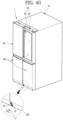
- Figures 1-16 , 21-25 , 28 , 29 , 38-41 , 44 , 45 and 48-50 show embodiments being useful for understanding the invention, which are outside the subject-matter of the claims.
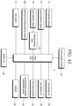
- Figures 17-20 , 26 , 27 , 30-37 , 42 , 43 , 46 and 47 show embodiments according to the present invention, which disclose a refrigerator according to claim 1.
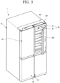
- FIG. 1 is a perspective view of a refrigerator according to an embodiment and FIG. 2 is a front view illustrating a state in which all doors of the refrigerator are opened. And FIG. 3 is a perspective view illustrating a state in which a sub-door of the refrigerator is opened.
- an external appearance of a refrigerator 1 may be formed by a cabinet 10 which forms a storage space and a door which opens and closes the storage space.
- An inside of the cabinet 10 may be divided up and down by a barrier 11, and a refrigerator compartment 12 may be formed at an upper portion of the cabinet 10, and a freezer compartment 13 may be formed at a lower portion of the cabinet 10.
- various accommodation members 121 such as a shelf, a drawer and a basket may be provided inside the refrigerator compartment 12. If necessary, the accommodation members 121 may be inserted and withdrawn while the door is opened, and may accommodate and store food by the inserting and withdrawing.
- a main lighting unit 85 which illuminates the refrigerator compartment 12 may be provided at the refrigerator compartment 12. The main lighting unit 85 may also be disposed at the freezer compartment 13, and may also be disposed at any positions of an inner wall surface of the refrigerator 1.
- the door may include a refrigerator compartment door 20 and the freezer compartment door 30.
- the refrigerator compartment door 20 serves to open and close an opened front surface of the refrigerator compartment 12 by rotation
- the freezer compartment door 30 serves to open and close an opened front surface of the freezer compartment 13 by rotation.
- one pair of refrigerator compartment doors 20 and one pair of freezer compartment doors 30 may be provided left and right to shield the refrigerator compartment 12 and the freezer compartment 13, respectively.
- a plurality of door baskets may be provided at the refrigerator compartment door 20 and the freezer compartment door 30.
- the door baskets may be provided so as not to interfere with the accommodation members 121 and 131 while the refrigerator compartment door 20 and the freezer compartment door 30 are closed.
- the refrigerator compartment door 20 and the freezer compartment door 30 forms an entire exterior when being seen from a front.
- the exterior of each of the refrigerator compartment door 20 and the freezer compartment door 30 may be formed of a metallic material, and the entire refrigerator 1 may have a metallic texture.
- a dispenser which dispenses water or ice may be provided at the refrigerator compartment door 20.
- the main door 40 may be formed to have the same size as that of a left one (in FIG. 1 ) of the pair of refrigerator compartment doors 20, may be rotatably installed at the cabinet 10 by a main hinge 401 and a middle hinge 402, and thus may open and close a part of the refrigerator compartment 12.
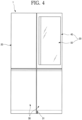
- FIG. 4 is a front view illustrating a state in which the sub-door is opaque.
- the sub-door 50 when there are not any operations in the refrigerator 1 while all of the main door 40 and the sub-door 50 are closed, the sub-door 50 may have an opaque black color or may be in a state like a mirror surface. Therefore, the sub-door 50 may not enable an internal space of the sub-door 50, i.e., an accommodation space of the main door 40 and an internal space of the refrigerator compartment 12 to be visible.
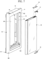
- the outer plate 41 may be formed of a plate-shaped stainless material, and may be formed to be bent and thus to form a part of a front surface and a perimeter surface of the main door 40.
- the door liner 42 may be injection-molded with a plastic material, and forms the rear surface of the main door 40. And the door liner 42 may also be formed so that an area thereof corresponding to the opening part 403 is opened.
- the opening part 403 may have a plurality of uneven structures so that the door basket 404 is installed.
- a rear gasket 44 may be provided at a perimeter of a rear surface of the door liner 42.
- the rear gasket 44 is in close contact with a perimeter of the cabinet 10, and prevents a leak of cooling air between the main door 40 and the cabinet 10.
- a door lighting unit 49 which illuminates the inside of the opening part 403 may be provided at an upper surface of the door liner 42.
- the door lighting unit 49 may emit light downward from an upper side of the opening part 403, and thus may illuminate the entire opening part 403 including the door basket 404, and may also enable the sub-door 50 to be in the transparent state.
- the cap decorations 45 and 46 form an upper surface and a lower surface of the main door 40, and a hinge installation part 451 which enables the main door 40 to be rotatably installed at the cabinet 10 may be formed at each of the cap decorations 45 and 46.
- An upper end of the main door 40 may be coupled to the main hinge 401, and a lower end of the main door 40 may be coupled to the middle hinge 402, and thus the upper and lower ends of the main door 40 may be rotatably supported.
- a door handle 462 may be formed to be recessed from the lower surface of the main door 40, i.e., the cap decoration 46. The user may put a hand into the door handle 462, may rotate the main door 40, and thus may open and close the refrigerator compartment 12.
- a door frame 43 may be further provided between the outer plate 41 and the door liner 42.
- the door frame 43 may be coupled between the outer plate 41 and the door liner 42, and may form a perimeter of the opening part 403.
- a foaming solution may be filled inside an internal space of the main door 40, and thus an insulation may be formed therein. That is, the insulation may be disposed at a perimeter area of the opening part 403, and thus isolate a space inside the refrigerator 1 from a space outside the refrigerator 1.
- the door frame 43 may be injection-molded with a plastic material which is different from that of the door linier 42. If necessary, the door frame 43 may be integrally formed with the door liner 42, and may be directly coupled to the outer plate 41.
- a frame stepped part 431 which protrudes inward may be formed at an inner surface of the door frame 43. Therefore, when the sub-door 50 is closed, the frame stepped part 431 may support the sub-door 50.
- a front gasket 434 may be provided at the frame stepped part 431.
- the front gasket 434 is in contact with a rear surface of the sub-door 50 when the sub-door 50 is closed, and thus seals between the main door 40 and the sub-door 50.
- the front gasket 434 may be omitted, if necessary.
- the front gasket 434 may be formed in a sheet shape formed of a metallic material, and may also be formed to be in close contact with a sub-door gasket 591 having a magnetic force by the magnetic force.
- a frame heater 4321 may be provided at a rear surface of the frame stepped part 431.
- the frame heater 4321 is disposed along the frame stepped part 431, and heats the frame stepped part 431.
- the frame stepped part 431 may have a relatively low surface temperature due to an influence of cooling air in the refrigerator 1. Therefore, dew condensation may occur on a surface of the frame stepped part 431. The dew condensation may be prevented by driving of the frame heater 4321.
- a hinge hole 433 in which each of sub-hinges 51 and 52 for installing the sub-door 50 is installed is formed at each of both sides of the door frame 43.
- the hinge hole 433 is formed at a position which faces a side surface of the sub-door 50, and also formed so that each of the sub-hinges 51 and 52 is inserted therein.
- a hinge case 47 may be provided at the inner surface of the door frame 43 (which is in contact with the insulation) corresponding to the hinge hole 433.
- the hinge case 47 is formed by vertically coupling a first case 471 and a second case 472 to each other.
- the hinge case 47 forms a space which rotatably accommodates a part of each of the sub-hinges 51 and 52 inserted through the hinge hole 433 when the first case 471 and the second case 472 are coupled to each other.
- a hinge installation member 473 is provided at a recessed space of the hinge case 47.
- the hinge installation member 473 may be fixed by the coupling of the first case 471 and the second case 472.
- the hinge installation member 473 may be formed of a steel material, and may have a shaft insertion part 4731 in which a hinge shaft of each of the sub-hinges 51 and 52 is inserted.
- the hinge case 47 may be installed at the hinge hole 433 which is formed at each of upper and lower portions of the door frame 43. And the hinge cases 47 which are disposed up and down may be formed to have the same structure and shape.
- a hinge frame 48 may be provided at an outside of the door frame 43.
- the hinge frame 48 is formed to vertically extend, and fixes the hinge cases 47 which are disposed up and down.
- the hinge frame 48 may be formed of a metallic material or a plastic material having excellent strength, may be formed in a plate shape, and may be formed to vertically extend. An upper end 482 and a lower end 483 of the hinge frame 48 may be bent, and then may be coupled and fixed to the cap decorations 45 and 46 provided at the upper and lower ends of the main door 40. That is, the upper end 482 and the lower end 483 of the hinge frame 48 are fixed to the cap decorations 45 and 46, and thus an installation position thereof may be maintained, and also the hinge frame 48 indirectly supports the sub-hinges 51 and 52.
- a case fixing part 481 may be formed at each of upper and lower portions of the hinge frame 48.
- the case fixing part 481 may be formed by cutting away a part of the hinge frame 48. Therefore, a portion of the hinge case 47 which forms the recessed space may be accommodated and fixed into the cut-away case fixing part 481 of the hinge frame 48.
- the hinge case 47 may be coupled to the hinge frame 48 by a separate fastening member such as a screw.
- a frame reinforcing part 484 may be formed between the case fixing parts 481, which are formed at the upper and lower portions of the hinge frame 48, to be recessed. And a plurality of frame openings 485 may be formed at the frame reinforcing part 484.
- the frame reinforcing part 484 may reinforce strength of the hinge frame 48, may prevent the hinge frame 48 from being bent or deformed, and may also maintain an installation position of the hinge case 47.
- the foaming solution when the foaming solution is injected into the main door 40, a surface area is increased, and thus adhesion with the foaming solution is enhanced. Also, the foaming solution may pass through the frame openings 485, and thus flowability of the foaming solution may be improved.
- the hinge frame 48 When the insulation is molded, the hinge frame 48 may be buried and fixed in the insulation.
- the sub-hinges 51 and 52 may include an upper hinge 51 which is installed at an upper end of the sub-door 50 and a lower hinge 52 which is installed at a lower end of the sub-door 50. And the upper hinge 51 and the lower hinge 52 may extend laterally toward the hinge hole 433, and may be coupled at an inside of the main door 40.
- the sub-hinges 51 and 52 may be installed at accurate positions, and may have a structure which extends laterally. Accordingly, since there is not an interfering structure with the sub-hinges 51 and 52 at a gap between the main door 40 and the sub-door 50, a distance between the main door 40 and the sub-door 50 may be maintained in a very narrow state, and the exterior may be further enhanced. Also, since the distance between the main door 40 and the sub-door 50 is maintained in the very narrow state, and deflection of the sub-door 50 is effectively prevented, the interference with the main door 40 upon the rotation of the sub-door 50 may be prevented.
- a hinge cover 53 which shields the upper hinge 51 and guides access of an electric wire of the sub-door 50 may be further provided at an upper side of the upper hinge 51.
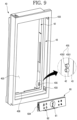
- FIG. 9 is an exploded perspective view of the main door and the display unit.
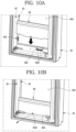
- FIGS. 10A and 10B are partial perspective views illustrating an installing state of the display unit.
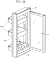
- the display unit 60 may be provided at the opening part 403 of the main door 40.
- the display unit 60 serves to display an operation state of the refrigerator 1 and also to operate the refrigerator 1, and is formed so that the user recognizes through the sub-door 50 from an outside when the sub-door 50 is in the transparent state. That is, the display unit 60 is not visible from the outside while the sub-door 50 is in the opaque state, but may indicate a variety to information to the outside while the sub-door 50 is in the transparent state.
- the display unit 60 may include a display 61 which displays state information of the refrigerator 1, and various operating buttons 62 which set the operation of the refrigerator 1.
- the operation of the refrigerator 1 may be operated by the operating buttons 62.
- the display unit 60 may be separably provided at a lower end of the opening part 403. Therefore, when it is necessary to check or repair the display unit 60, the display unit 60 may be separated. And after the main door 40 is assembled, the display unit 60 which is assembled as a separate module may be simply installed. Also, the display unit 60 which has a necessary function according to a specification of the refrigerator 1 may be selectively installed.
- the display installing protrusion 435 may be formed by protruding a side surface of the opening part 403, more specifically, a part of the door liner 42 and a part of the door frame 43. That is, the display installing protrusion 435 is formed by coupling a liner side installation part 4352 and a frame side installation part 4351 to each other, and may be formed in a protrusion shape having a circular cross section. Therefore, when the display unit 60 is installed, the display installing protrusion 435 is maintained in an installed state, and thus coupling between the door liner 42 and the door frame 43 may be more firmly maintained.
- a plurality of display installing protrusions 435 may be formed and may be arranged vertically.
- a door connector 4361 may be provided at the display connection part 436.
- the door connector 4361 may be connected with an electric wire which supplies electric power for an operation of the display unit 60 and transmits a signal, and may be electrically connected with the display unit 60 by a separable structure of the display 61.
- the door connector 4361 protrudes upward from a bottom surface of the display connection part 436, and may be coupled and electrically connected to a display connector 651 provided at a bottom of the display unit 60 when the display unit 60 is installed.
- a plurality of door connectors 4361 may be provided, and may be formed separately according to functions of the display unit 60. That is, the door connectors 4361 may be independently formed corresponding to the display 61 and the operating buttons 62 of the display unit 60, and may also be formed so that the separate electric power and signal are transmitted to each of them.
- a case extension part 635 is formed at a lower end of a rear surface of the display unit 60.
- a screw hole 6351 in which a screw is fastened is formed at the case extension part 635, and thus the display unit 60 may be maintained in a coupled state to the main door 40.
- FIG. 11 is a cross-sectional view illustrating an installed state of the display unit.
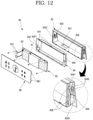
- FIG. 12 is an exploded perspective view of a display assembly.
- the display unit 60 may include an outer case 63 which forms an external appearance, an inner case 64 which is provided inside the outer case 63, a display PCB 65 and a display cover 66.
- the outer case 63 forms an entire exterior of the display unit 60, and has an accommodation space formed therein to accommodate the inner case 64.
- the accommodation space is opened forward, and a connector opening 631 for coupling to the door connector 4361, through which the electric wire connected to the display connector 651 passes, may be formed at a bottom surface of the accommodation space.
- the display connector 651 may be provided at a lower side of the connector opening 631, and if necessary, the display connector 651 may be fixed to the connector opening 631.
- the display connector 651 and the door connector 4361 may be coupled and connected to each other by moving the display unit 60 up and down.
- the power supplying and the signal transmitting to the display unit 60 may be enabled.
- a plurality of case coupling protrusions 632 which protrude to be coupled to the inner case 64 are formed at inner upper and lower ends of the accommodation space.
- the case coupling protrusions 632 may be formed at an opened entrance side of the accommodation space, and may be formed at regular intervals.
- a case support part 633 which supports the inner case 64 is formed to protrude inward from both of left and right sides of an inner surface of the accommodation space.
- a screw hole 6331 in which a screw is inserted may be further formed at the case support part 633, and the inner case 64 may be installed and fixed to the case support part 633.
- the display guide 634 is formed at both of left and right side surfaces of the outer case 63.
- the display guide 634 may be formed in a rib shape which protrudes from both of the left and right side surfaces of the outer case 63.
- the display guide 634 is formed to be opened downward, and the display installing protrusion 435 may be inserted through an opened lower side thereof.
- the display guide 634 is formed so that a width thereof becomes narrower upward from an opened entrance 6343 thereof.
- An upper end 6341 of the display guide 634 may be formed to have the same size as a diameter of the display installing protrusion 435. Therefore, the display installing protrusion 435 may be easily inserted into the display guide 634, and may be restricted by the upper end 6341 of the display guide 634.
- the inner case 64 may be injection-molded with a plastic material, and may provide a space in which the display PCB 65 is installed.
- a center of the inner case 64 is formed to be recessed with a size corresponding to the display PCB 65, and a plurality of case coupling grooves 641 are formed at a perimeter of the inner case 64, and the case coupling protrusion 632 is coupled therein.
- a case seating part 642 which extends laterally and is seated on the case support part 633 is formed at both side surfaces of the inner case 64.
- the inner case 64 is coupled to the outer case 63 by a screw fastened into a screw hole 6421 of the case seating part 642.
- a case hole 643 is formed at one side surface of the inner case 64.
- the case hole 643 serves as a passage of the electric wires connected to the display PCB 65, and the electric wires may pass through the case hole 643, and may be connected to the display connector 651 through the connector opening 631.
- the display PCB 65 may be accommodated in a space formed inside the inner case 64.
- the display 61 and the plurality of operating buttons 62 may be installed at the display PCB in the form of a module. And elements on the display PCB 65 may be covered and sealed with a resin material for waterproofing and moisture-proofing.
- the display 61 may be formed in a panel type which displays the operation state and operation information of the refrigerator 1. And the plurality of operating buttons 62 may be provided at both of left and right sides of the display 61, and may be formed to be operated by a user's operation which pushes the display cover 66.
- the display PCB 65 is installed at the inner case 64, the inner case 64 is accommodated inside the outer case 63, and the display 61 is coupled so as to shield an opening of the outer case 63. Therefore, the display PCB 65 and the inner case 64 may be shielded by the display 61.
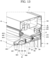
- FIG. 13 is a cross-sectional view taken along line 13-13' of FIG. 1 .
- the lamp cover 493 is formed to extend long along the door liner 42, and includes a recessed part 4914 which forms a recess space therein to accommodate the lamp PCB 492. Specifically, a surface of the recessed part 4914 which faces the lamp PCB 492 may be formed to be rounded, and light emitted from the lamp PCB 492 is reflected by a rounded surface 4915 having a predetermined curvature, and directed to the lamp case 491. A film which increases the reflectivity of the light may be attached to or coated on an inner surface of the recessed part 4914, particularly, the rounded surface 4915.
- a first case installation part 4911 and a second case installation part 4912 are formed at both ends of the recessed part 4914.
- the first case installation part 4911 and the second case installation part 4912 are installed to be in surface contact with inner side surfaces of the door liner 42 and the door frame 43, respectively, and thus the lamp case 491 may be hooked and restricted or adhered inside the main door 40.
- cover insertion grooves 4916 and 4917 may be formed at the first case installation part 4911 and the second case installation part 4912.
- the cover insertion grooves 4916 and 4917 may be formed to be stepped, and thus a space in which both ends of the lamp cover 493 are inserted when the lamp case 491 is installed may be formed between the first case installation part 4911 and the door liner 42 and between the second case installation part 4912 and the door frame 43.
- the lamp cover 493 is formed so that the light reflected by the rounded surface 4915 of the recessed part 4914 is transmitted therethrough.
- the lamp cover 493 serves to shield an opening of the recessed part 4914 and also to shield a space between the door liner 42 and the door frame 43.
- the lamp cover 493 is formed to be transparent or translucent, such that the light reflected by the rounded surface 4915 and uniformly spread is transmitted therethrough. Therefore, the light passing through the lamp cover 493 illuminates the inside of the refrigerator 1 in an indirect illumination method, and have an effect like surface emitting.
- FIG. 14 is an exploded perspective view of an installation structure of a door opening device and FIG. 15 is a view illustrating an operation state of the door opening device.
- the opening device accommodation part 452 is formed at the cap decoration 45 on an upper surface of the main door 40. And a door opening device 70 may be provided inside the opening device accommodation part 452. An opened upper surface of the opening device accommodation part 452 is shielded by the cap decoration cover 453.
- the door opening device 70 for automatically opening the main door 40 may include a driving motor 72 which is provided inside an opening device case 71, a push rod 74 which pushes and opens the main door 40, and gears 73 which transmits power of the driving motor 72 to the push rod 74.
- the push rod 74 is formed to have a predetermined curvature. Therefore, even when the main door 40 is rotated, a front end of the push rod 74 may continuously push the cabinet 10 while being maintained in a stably contacting state with a front surface of the cabinet 10, and thus may open the main door 40.
- a front support part 437 which is bent to support the outer plate 41 may be formed at a front end of the door frame 43.
- a front accommodation part 4371 in which an end of the outer plate 41 is introduced in a bent state may be formed at an end of the front support part 437.
- the multi-bent part 411 is bent at a portion forming the front surface of the main door 40 to have a predetermined slope, and forms a first bent part 4111.
- An inclined surface of the first bent part 4111 may be formed to be directed toward the opening part 403, and an end of the first bent part 4111 forms one end of the opening part 403.
- the handle 561 forms one side surface of the sub-door 50, and is formed long vertically, and also formed to have a predetermined space between the one side surface of the sub-door 50 and one end of the opening part 403, such that the user puts his/her hand therein and then pulls.
- the first side frame 55 is formed long vertically, and also formed to connect between the upper hinge 51 and the lower hinge 52.
- hinge insertion parts 551 and 552 in which the upper hinge 51 and the lower hinge 52 are inserted are formed at upper and lower ends of the first side frame 55, respectively.
- the hinge insertion parts 551 and 552 are formed at the upper and lower ends of the first side frame 55 to be recessed, and may be formed to have a corresponding shape, such that a part of the upper hinge 51 and the lower hinge 52 is matched therewith.
- the first side frame 55 may be formed of a metallic material such as aluminum or a material having high strength, and may enable the upper hinge 51 and the lower hinge 52 to be maintained at accurate installation positions, such that the installation positions are not changed by a weight of the sub-door 50. Therefore, the sub-door 50 may maintain an initial installation position at the main door 40, and an outer end of the sub-door 50 and the opening part 403 of the main door 40 may not interfere with each other when being rotated, and may maintain a very closely contacting state with each other.
- the second side frame 56 may be formed of the metallic material or the material having high strength.
- the second side frame 56 may be formed to extend from the upper end of the sub-door 50 to the lower end thereof, and may have the handle 561 which is recessed to allow the user to put his/her hand therein.
- the sub-door liner 59 forms a shape of a perimeter of the rear surface of the sub-door 50, and may be injection-molded with a plastic material.
- the sub-door liner 59 is coupled to the first side frame 55, the second side frame 56, the upper cap decoration 57 and the lower cap decoration 58.
- the foaming solution is injected into an internal space of a perimeter of the sub-door 50 formed by the sub-door liner 59, and the insulation (not shown) is filled therein, and thus an insulation structure of the perimeter of the sub-door 50 is provided.
- the sub-door gasket 591 is provided at a rear surface of the sub-door liner 59.
- the sub-door gasket 591 is formed to be in close contact with the main door 40 when the sub-door 50 is closed. Therefore, the leak of the cooling air between the main door 40 and the sub-door 50 may be prevented.
- FIG. 20 is a cut-away perspective view taken along line 20-20' of FIG. 17 .
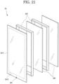
- FIG. 21 is an exploded perspective view of the panel assembly according to an embodiment of the present invention.
- a bezel 5411 is formed along a perimeter of the rear surface of the front panel 541.
- the bezel 5411 may be formed so that the light is not transmitted therethrough, and thus the side frames 55 and 56, the upper cap decoration 57, the lower cap decoration 58 and the spacer bar 543 which are coupled to the front panel 541 are prevented from being exposed forward through the front panel 541.
- a penetration part 5412 may be formed at a position corresponding to the second detection device 81.
- the penetration part 5412 may be formed in a shape corresponding to a front surface of the second detection device 81, and the bezel 5411 is not printed thereon.
- the insulation panel 542 may be formed to have a size smaller than that of the front panel 541, and may be located within an internal area of the front panel 541. And the insulation panel 542 may be chemical strengthening glass in which glass is soaked in an electrolyte solution at a glass transition temperature or more, and thus chemically strengthened.
- a low-radiation coating layer for reducing heat transfer into the storage compartment due to radiation may be formed at a rear surface of the insulation panel 542.
- Glass on which the low-radiation coating layer is formed is referred to as low- ⁇ glass.
- the low-radiation coating layer may be formed by sputtering silver or the like on a surface of the glass.
- a sealed space between the front panel 541 and the insulation panel 542 and a sealed space between the plurality of insulation panels 542 which are formed by the spacer bar 543 may create a vacuum state so as to be insulated.
- an inert gas for the insulation such as argon
- argon an inert gas for the insulation
- the inert gas has more excellent insulation property than that of general air. Therefore, insulation performance may be ensured by forming a predetermined space between the front panel 541 and the insulation panel 542 and between the plurality of insulation panels 542 in which the inert gas is filled.
- FIG. 22 is a cross-sectional view schematically illustrating an example of a front panel of the panel assembly.
- the front panel 541 may include a glass layer 5413 which forms an exterior, a vacuum deposition layer 5414 which is formed at a rear surface of the glass layer 5413, a bezel print layer 5415 which is formed at a rear surface of the vacuum deposition layer 5414, and a transparent print layer 5416 which forms entire rear surfaces of the bezel print layer 5415 and the vacuum deposition layer 5414.
- the vacuum deposition layer 5414 serves to enable the front panel 541 to have a half glass property, and may be formed at the rear surface of the glass layer 5413 by vacuum-depositing a titan compound (TiO 2 ). That is, the vacuum deposition layer 5414 is formed at the entire rear surface of the glass layer 5413. While the door lighting unit 49 is not turned on, the light is reflected by the vacuum deposition layer 5414, and thus the front panel 541 looks like a mirror when being seen from a front.
- a titan compound TiO 2
- the bezel print layer 5415 forms the perimeter of the rear surface of the front panel 541, and the bezel 5411 may be formed by the bezel print layer 5415.
- the bezel print layer 5415 is formed so that the light is not transmitted therethrough even while the door lighting unit 49 is turned on, and thus elements which are disposed along the perimeter of the rear surface of the front panel 541 may be shielded.
- the transparent print layer 5416 may be formed at the entire rear surface of the front panel 541 including the bezel print layer 5415 and the vacuum deposition layer 5414.
- the transparent print layer 5416 may be formed to be transparent, such that the light is transmitted therethrough, and serves to protect the front panel 541 while the front panel 541 or the panel assembly 54 is processed.
- the transparent print layer 5416 prevents the vacuum deposition layer 5414 from being damaged.
- the front panel 541 is formed so that the spacer bar 543 or the like is attached thereto.
- the front panel 541 may be manufactured separately from the insulation panel 542, and then transported.
- the vacuum deposition layer 5414 may be damaged, and thus may not perform a half glass function. Therefore, in a structure in which the vacuum deposition layer 5414 is formed at the rear surface of the glass layer 5413, the transparent print layer 5416 should be provided.
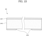
- FIG. 23 is a cross-sectional view schematically illustrating another example of the front panel of the panel assembly.
- the front panel 541 may include a glass layer 5413 which forms an exterior, a ceramic print layer 5417 which is formed at a front surface of the glass layer 5413, and a bezel print layer 5415 which is formed at a rear surface of the glass layer 5413.
- the glass layer 5413 is formed of a glass material through which the light is transmitted, and also which is seen through.
- a glass material called dark gray glass which imperceptibly has a dark gray color in a transparent state may be used.
- the ceramic print layer 5417 is formed at the entire front surface of the glass layer 5413, and may be formed in a silk screen printing using reflectance ink which reflects the light.
- the reflectance ink includes the titan compound (TiO 2 ) as a main component, a viscosity-controlling resin, an organic solvent, and an additive.
- the reflectance ink may be manufactured to have a predetermined viscosity for the silk screen printing.
- the ceramic print layer 5417 may be formed in a thickness of 40 to 400 nm. And the ceramic print layer 5417 may have flatness similar to a mirror surface through the silk screen printing using the reflectance ink, and may also be formed like the mirror surface when being reinforced by heating.
- the ceramic print layer 5417 is separately formed on the surface of the glass layer 5413, and has a different refractive index from that of the glass. Therefore, some of the light incident from the outside of the refrigerator 1 to the front panel 541 may be reflected by the ceramic print layer 5417, and the rest may be reflected by the glass layer 5413, and may have an effect like the mirror due to an interference effect of the light which is reflected. That is, due to the interference effect of the light which is reflected by a boundary surface of another medium having a different refractive index, the front panel 541 may look like the mirror when being seen from an outside.
- the front panel 541 may look transparent when being seen from the outside of the refrigerator 1, and the space in the refrigerator 1 may be visible.
- the ceramic print layer 5417 is formed so that the transmittance of the front panel 541 is about 20% to 30%.
- the transmittance is 20% or less, it is difficult to see through the space in the refrigerator 1 due to a low transparency of the front panel 541 even while the door lighting unit 49 is turned on.
- the transmittance is 30% or more, the space in the refrigerator 1 is visible even while the door lighting unit 49 is turned off, and thus the surface effect like the mirror may not be expected. Therefore, for the half mirror effect, it is preferable that transmittance of the front panel 541 is about 20% to 30%.
- the ceramic print layer 5417 is reinforced by heating to a predetermined temperature. An organic component is completely removed through the heating, and the titan compound (TiO 2 ) is calcined on the glass layer 5413.
- the heating is performed at a high temperature so that the organic component of the reflectance ink is completely removed, and the titan compound is calcined.
- the heating is performed at an excessively high temperature, bending may occur. Therefore, it is preferable that the heating is performed within a range at which the surface is not deformed. And for removing of the organic component and calcination of the titan compound, the front panel 541 may be heated in stages at different temperatures.
- the bezel print layer 5415 forms the perimeter of the rear surface of the front panel 541, and the bezel 5411 may be formed by the bezel print layer 5415.
- the bezel print layer 5415 is formed so that the light is not transmitted therethrough even while the door lighting unit 49 is turned on, and thus may shield the elements which are disposed along the perimeter of the rear surface of the front panel 541.
- the bezel print layer 5415 may be formed in an inorganic printing method (glass printing).
- the bezel print layer 5415 may be printed using a ceramic pigment as a main component in which frit, an inorganic pigment and oil are mixed. Therefore, in the bezel print layer 5415, the resin is decomposed and volatilized by the heating in the glass reinforcing process, and the frit melts and covers the pigment, and then may be attached on the surface of the glass layer 5413.
- Such an inorganic printing method has smaller fragments and higher durability than an organic printing method.
- a glass component may melt and may be integrally molded with the glass layer 5413, and thus in a multi-layering process with the additional insulation panel 542, it is possible to reduce heat loss and also to provide an excellent adhesive property.
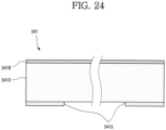
- FIG. 24 is a cross-sectional view schematically illustrating still another example of the front panel of the panel assembly.
- the gray glass has a somewhat brighter color than the dark gray glass described in the above-described example embodiment. This difference may be caused by a difference between the ceramic print layer 5417 and the hard coating layer 5418 which are formed on the glass layer 5413.
- the hard coating layer 5418 is formed at the entire front surface of the glass layer 5413, and also formed to have a light transmittance of 25 to 50% and a reflectivity of 45 to 65%, and to have a half mirror property, such that the transmittance and the reflectivity may be simultaneously increased.
- the hard coating layer 5418 may be formed in a thickness of about 30 to 80 nm, and may be configured with triple layers of iron, cobalt and chrome. Of course, one or two layers of the triple layers may be omitted, considering the transmittance, the reflectivity and a color difference.
- the hard coating layer 5418 may be formed in an atmospheric pressure chemical vapor deposition (APCVD) method in which a vaporized coating substance is formed on the entire surface of the glass layer 5413, or in a spraying method in which a liquid coating material is sprayed.
- APCVD atmospheric pressure chemical vapor deposition
- the hard coating layer 5418 is separately formed on the surface of the glass layer 5413, and has a different refractive index from that of the glass layer 5413. Therefore, some of the light incident from the outside of the refrigerator 1 to the front panel 541 may be reflected by the hard coating layer 5418, and the rest may be reflected by the glass layer 5413. Therefore, the front panel 541 may have an effect like the mirror due to an interference effect of the light which is reflected. That is, due to the interference effect of the light which is reflected by a boundary surface of another medium having a different refractive index, the front panel 541 may look like the mirror when being seen from an outside.
- the bezel print layer 5415 forms the perimeter of the rear surface of the front panel 541, and the bezel 5411 may be formed by the bezel print layer 5415.
- the bezel print layer 5415 is formed so that the light is not transmitted therethrough even while the door lighting unit 49 is turned on, and thus may shield the elements which are disposed along the perimeter of the rear surface of the front panel 541.
- the bezel print layer 5415 may be formed in the inorganic printing method.
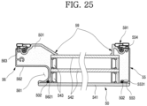
- FIG. 25 is a cross-sectional view of a sub-door.
- the case fixing part 481 to which a screw for fixing the accommodation part cover 583 to the lower cap decoration 58 is fastened is formed at one side of the accommodation part cover 583.
- An injection port cover part 5831 is further formed at the other side of the accommodation part cover 583.
- the injection port cover part 5831 is formed on the lower cap decoration 58, and also formed to shield a first injection port 5824 through which the foaming solution filled to mold an insulation 501 is injected.
- a plurality of hook parts 5832 are formed at an upper surface of the injection port cover part 5831 to be fitted into the first injection port 5824.
- the injection port cover part 5831 is fitted into the first injection port 5824, and the case fixing part 481 is fixed to the lower cap decoration 58 by fastening the screw, and the entire accommodation part cover 583 is installed and fixed to the lower cap decoration 58.
- the detection device accommodation part 582 When the accommodation part cover 583 is installed at the lower cap decoration 58, the detection device accommodation part 582 may be shielded, and the first injection port 5824 may also be shielded.
- a PCB installation part 5833 is further formed at the accommodation part cover 583.
- a detection device PCB 83 for processing a signal of the second detection device 81 and the knock detection device 82 is installed at the PCB installation part 5833.
- the detection device PCB 83 may be connected to the second detection device 81 and is connected to the knock detection device 82, and may be seated at the PCB installation part 5833.
- the detection device PCB 83 may serve to process the signal of the second detection device 81 and serves to process the signal of the knock detection device 82, and is located at a position close to the second detection device 81 and the knock detection device 82, and configured to process the signals.
- the detection device PCB 83 for processing the signal is located at a distance, there may be a problem that noise generated when the signal to be processed is transferred through a signal line may be increased.
- the detection device PCB 83 since the detection device PCB 83 is located at a position at which the second detection device 81 and the knock detection device 82 are installed, a main control part 2 receives only a valid knock-on signal. Accordingly, the noise due to the signal line between the main control part 2 and the detection device PCB 83 may be minimized. That is, the main control part 2 may receive the signal of which the noise is minimized through the detection device PCB 83. Therefore, it is possible to ensure an accurate recognition rate.
- the main control part 2 which controls an entire operation of the refrigerator 1 generally receives a signal which is basically indicated by V unit. Therefore, due to a scale difference in a physical signal, it is not preferable that the main control part 2 determines whether the knock-on signal is normal.
- the refrigerator 1 is an electronic appliance using a high voltage/a high current. Therefore, an electrical noise generation amount is relatively great. This means that the signal of mV unit output from the microphone 8211 may be further vulnerable to the electrical noise.
- the detection device PCB 83 since the detection device PCB 83 is located close to the knock detection device 82, the noise may be remarkably reduced, and thus the recognition rate may be enhanced.
- a second injection port 584 through which the foaming solution is injected is further formed at one side of the lower cap decoration 58 close to the lower hinge 52.
- the second injection port 584 may be shielded by a separate injection port cover 5841.
- a plurality of hook parts 5842 are formed at an upper surface of the injection port cover 5841 to be fitted into the second injection port 584.
- a first boss 5821 to which a screw for fixing the second detection device 81 is fastened, and a second boss 5822 for fixing the knock detection device 82 are respectively formed at a bottom surface of the detection device accommodation part 582.
- an electric wire hole 5823 is formed at one surface of the detection device accommodation part 582.
- the electric wire L which is connected to the detection device PCB 83, the second detection device 81 and the knock detection device 82 may be guided to the outside of the sub-door 50 through the electric wire hole 5823.
- a through part 5825 which is opened so that the second detection device 81 and the knock detection device 82 are in close contact with the front panel 541 may be formed at a front surface of the detection device accommodation part 582 which is in contact with the front panel 541.
- FIG. 32 is an exploded perspective view of the knock detection device.
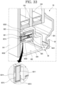
- FIG. 33 is a cross-sectional view taken along line 33-33' of FIG. 17 .
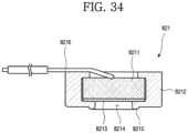
- FIG. 34 is a cross-sectional view of a microphone module of the knock detection device.
- the knock detection device 82 may include a microphone module 821 which detects the knock-on signal, a holder 823 which accommodates the microphone module 821, an elastic member 824 which presses the holder 823 and the microphone module 821 toward the front panel 541 so that the holder 823 and the microphone module 821 are in close contact with the front panel 541, and a support member 825 which supports the elastic member 824 and the holder 823.
- the microphone module 821 includes the microphone 8211 which directly senses a sound wave, and a microphone accommodation part 8212 which accommodates the microphone 8211.
- the microphone 8211 serves to directly sense the sound wave, is formed in a circular shape having a predetermined thickness, and installed and fixed into the microphone module 821.
- One surface of the microphone 8211 may be referred to as a sound wave receiving part 8213 which receives the sound wave, and the sound wave receiving part 8213 is disposed toward an opening 8214 of the microphone accommodation part 8212.
- the other side of the microphone 8211 may be connected to a signal line 8216, and the signal line 8216 may also be connected to the detection device PCB 83.
- the microphone accommodation part 8212 is formed of an elastic material such as rubber, and also formed to be in close contact with the front panel 541.
- the opening 8214 may be formed at one side of the microphone accommodation part 8212 close to the microphone 8211 installed in the microphone accommodation part 8212, and a circular protrusion 8215 may be formed at a circumference of the opening 8214.
- the protrusion 8215 serves to enable the microphone accommodation part 8212 not to be inclined in one direction when the microphone accommodation part 8212 is in close contact with the front panel 541, and also to enable an entire opened front surface of the opening part 403 to be maintained in a closely contacting state with the front panel 541.
- a predetermined sealed space may be formed between the opening 8214 and the sound wave receiving part 8213 which are in close contact with each other by the protrusion 8215. Therefore, a front of the closely contacting space is sealed by a medium, i.e., the front panel 541. Accordingly, vibration transmitted through an inside of the medium vibrates air in the predetermined space, and the sound wave due to the vibration may be received by the microphone 8211.
- a module seating part 8231 in which the microphone module 821 is accommodated and which is opened toward the front panel 541 may be formed at the holder 823.
- the microphone module 821 may be formed so that at least the protrusion 8215 protrudes further than a front surface of the holder 823 while the microphone module 821 is seated on the module seating part 8231.
- a holder slot 8232 through which the signal line connected to the microphone 8211 passes is formed at the holder 823.
- the holder slot 8232 is formed to be opened at one side of the module seating part 8231.
- a first elastic member fixing part 8233 which protrudes so that the elastic member 824 is installed and fixed thereto is formed at a rear surface of the holder 823.
- the first elastic member fixing part 8233 may be formed to extend and to pass through one end of the elastic member 824 having a coil shape.
- a holder coupling part 8234 which is formed in a hook shape and coupled to the support member 825 is formed at both sides of the holder 823. Due to the holder coupling part 8234, the holder 823 is coupled so as not to be separated by the support member 825. And also, due to the hook shape of the holder coupling part 8234, movement of the holder 823 in a direction which is inserted into the support member 825 is not restricted.
- a front surface of the support member 825 is formed to be opened, and also formed so that the holder 823 is inserted through the opened front surface thereof.
- a second elastic member fixing part 8251 which protrudes so that the elastic member 824 is installed and fixed thereto may be formed at an inside of the holder 823.
- the second elastic member fixing part 8251 may be located on an extension line of the first elastic member fixing part 8233, and may be inserted so as to pass through one end of the elastic member 824.
- the elastic member 824 may stably press the holder 823 toward the front panel 541 without being buckled.
- the microphone module 821 may be maintained in a closely contacting state with the front panel 541, and particularly, may be always maintained in the closely contacting state with the front panel 541 without a position change of the microphone module 821 due to a shock generated when the main door 40 and the sub-door 50 are closed and opened or an inertial force generated when the main door 40 and the sub-door 50 are rotated.
- a support member slot 8252 may be formed at one side of the support member 825.
- the support member slot 8252 may be formed on an extension line of the holder slot 8232. Therefore, the signal line passing through the holder slot 8232 may pass through the support member slot 8252, and may be connected to the detection device PCB 83.
- the knock detection device 82 is installed at the area of the bezel 5411 of the front panel 541, and thus the knock detection device 82 is not exposed to the outside when being seen from an outside of the front panel 541.
- the foaming solution injected to the second injection port 584 is first injected into the space formed by the lower cap decoration 58 and the panel assembly 54, and then flows continuously to the space between the first side frame 55 and the panel assembly 54.
- FIG. 44 is a perspective view illustrating an installed state of the display unit.
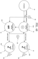
- FIG. 45 is a view illustrating a configuration of a front surface of the display unit.
- the display 61 is a screen through which the operation information of the refrigerator 1 is output, and may be selectively turned on and off according to the knocking operation on the front panel 541 or the opening and closing of the sub-door 50.
- the operating buttons 62 serve to set the operation of the refrigerator 1, and may include a communication button 621, a lock button 622, an auto-door button 623, an auto-drawer button 624, a refrigerator compartment temperature fixing button 625, a freezer compartment temperature fixing button 626, an air cleaning button 627, and a quick freezing button 628.
- a combination of the operating buttons 62 is just an example for convenience of explanation, and is not limited thereto.
- FIG. 46 is a view illustrating a change in a display state of the display unit according to a knocking operation on a refrigerator according to claim 1.
- the display 61 is maintained in an OFF state until the knocking operation on the front panel 541 is performed. And when the user knocks on the front panel 541, the display 61 is turned on. At this point, a first screen 611 or a second screen 612 which outputs a temperature in the refrigerator 1 and a present operating function may be output on the display 61.
- the display 61 is turned off.
- the main lighting unit 85 is also turned off, and the sub-door 50 is in the opaque state, and thus the display 61 is not visible from the outside.
- FIG. 47 is a view illustrating the change in the display state when the sub-door of a refrigerator according to claim 1 is opened and closed.
- the display 61 is turned off. And when the sub-door 50 is opened, the opening of the sub-door 50 is detected by the door switch 21, and the main control part 2 turns on the display 61.
- the operation information of the refrigerator 1 is displayed on the first screen 611, and the first screen 611 is changed into the second screen 612 after the preset time passes, and another operation information of the refrigerator 1 is displayed on the second screen 612.
- the information displayed on the first screen 611 and the second screen 612 may be set by the user's operation.
- the display 61 displays a third screen 613 which indicates an activated state of the door opening device 70 when the door opening device 70 is activated. And when the door opening device 70 is not activated, the display 61 displays a fourth screen 614 which indicates an inactivated state of the door opening device 70.
- the third screen 613 and the fourth screen 614 may be converted to each other, and a state of the door opening device 70 may also be substantially changed.
- the door opening device 70 when it is intended that the user does not use the door opening device 70, it may be set through operating of the auto-door button 623. And in this state, an operation of the door opening device 70 is not performed.
- the display 61 is converted to the first screen 611 or the second screen 612 which indicates the temperature in the refrigerator 1.
- the auto-door button 623 may be in an ON state, and when the door opening device 70 is inactivated, the auto-door button 623 may be in an OFF state.
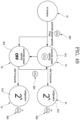
- FIG. 49 is a view illustrating the change in the display state of the display unit when an auto-drawer function is set.
- the display 61 displays a fifth screen 615 which indicates an activated state of the accommodation member withdrawing device 34 when the accommodation member withdrawing device 34 is activated. And when the accommodation member withdrawing device 34 is inactivated, the display 61 displays a sixth screen 616 which indicates an inactivated state of the accommodation member withdrawing device 34.
- the fifth screen 615 or the sixth screen 616 may be converted to each other, and a state of the accommodation member withdrawing device 34 may also be substantially changed.
- the accommodation member withdrawing device 34 when it is intended that the user does not use the accommodation member withdrawing device 34, it may be set through operating of the auto-drawer button 624. And in this state, an operation of the accommodation member withdrawing device 34 is not performed.
- the display 61 is converted to the first screen 611 or the second screen 612 which indicates the temperature in the refrigerator 1.
- the auto-drawer button 624 may be in an ON state, and when the accommodation member withdrawing device 34 is inactivated, the auto-drawer button 624 may be in an OFF state.
- FIG. 50 is a view illustrating the change in the display state of the display unit when the temperature fixing function is set.
- the main control part 2 may control the operation of the refrigerator 1 so that the temperature in the refrigerator 1 is maintained at a preset temperature, and a seventh screen 617 which indicates such a state is displayed. And when a refrigerator compartment temperature fixing mode is not set, the display 61 displays an eighth screen 618 which indicates an in activated state of the refrigerator compartment temperature fixing mode.
- the seventh screen 617 or the eighth screen 618 may be converted to each other, and an operation mode of the refrigerator 1 may also be substantially changed.
- the refrigerator compartment temperature fixing mode when it is intended that the user does not use the refrigerator compartment temperature fixing mode, it may be set through operating of the refrigerator compartment temperature fixing button 625. And in this state, an operation of the refrigerator compartment temperature fixing mode is not performed.
- the display 61 is converted to the first screen 611 or the second screen 612 which indicates the temperature in the refrigerator 1.
- the refrigerator compartment temperature fixing button 625 may be in an ON state, and when the refrigerator compartment temperature fixing mode is inactivated, the refrigerator compartment temperature fixing button 625 may be in an OFF state.
- a state of the display 61 is changed in the above-described manner, except contents of the screen, and thus detailed description thereof will be omitted.
- the panel assembly which selectively transmits or reflects the light is provided at a part of the door, and the lighting unit which is turned on or off by the user's operation is provided inside the door, and the lighting unit can be turned on by the user's operation while the door is closed, and thus it is possible to see through the inside of the refrigerator.
- the door can be prevented from being unnecessarily opened and closed, and loss of the cooling air can be prevented, and thus it is possible to improve power consumption and also to enhance storage performance.
- the panel assembly has a structure like a half glass which is seen through while the lighting unit is turned on, and functions as a mirror while the lighting unit is not turned on, and thus an exterior of the refrigerator door can be enhanced.
- the microphone which detects a sound generated by the vibration upon the user's knocking operation on the panel assembly can be provided at the rear surface of the panel assembly. Therefore, the lighting unit can be turned on or off by the user's knocking operation, and thus the panel assembly can be selectively transparent.
- the panel assembly can become transparent by the simple operation, and the sound of the vibration transmitted through the same medium is the same even though the user knocks on any positions of the front surface of the panel assembly, the operation can be easily performed, and effectively detected.
Landscapes
- Engineering & Computer Science (AREA)
- General Engineering & Computer Science (AREA)
- Physics & Mathematics (AREA)
- Thermal Sciences (AREA)
- Chemical & Material Sciences (AREA)
- Combustion & Propulsion (AREA)
- Mechanical Engineering (AREA)
- General Physics & Mathematics (AREA)
- Cold Air Circulating Systems And Constructional Details In Refrigerators (AREA)
- Refrigerator Housings (AREA)
Claims (9)
- Kühlschrank, aufweisend:ein Gehäuse (10), das einen Aufbewahrungsraum bildet;eine Haupttür (40), die den Aufbewahrungsraum öffnet und schließt und einen Öffnungsteil (403) aufweist;eine Nebentür (50), die drehbar an der Haupttür (40) angebracht ist und den Öffnungsteil (403) öffnet und schließt;eine in der Nebentür (50) vorgesehene Plattenanordnung (54), die aus einem Halbspiegel besteht, der einen Teil des Lichts reflektiert und einen Teil des Lichts durchlässt, um selektiv transparent zu sein und um selektives Betrachten eines Inneren des Öffnungsteils (403) durch einen Benutzer zu ermöglichen;eine Beleuchtungseinheit (85), die im Inneren des Kühlschranks vorgesehen ist, um Licht zur Beleuchtung des Lagerraums zu emittieren, wobei das Licht von der Beleuchtungseinheit (85) durch die Plattenanordnung (54) dringt,wobei der Kühlschrank das Betrachten eines Inneren des Kühlschranks ermöglicht, während die Beleuchtungseinheit (85) eingeschaltet ist, und eine Spiegelfläche bildet, während die Beleuchtungseinheit (85) ausgeschaltet ist; undeine im Kühlschrank vorgesehene Anzeigeeinheit (60), um einen Betriebszustand des Kühlschranks anzuzeigen;eine Klopferfassungsvorrichtung (82), die in der Nebentür (50) vorgesehen ist und einen Klopfvorgang eines Benutzers erfasst;wobei, in dem Fall, in dem der Klopfvorgang des Benutzers verifiziert wird, die Beleuchtungseinheit (85) gemäß der Klopferfassungsvorrichtung (82) eingeschaltet wird, die den Klopfvorgang des Benutzers auf einer Vorderseite der Nebentür (50) erfasst, während die Nebentür (50) geschlossen ist, um die Plattenanordnung (54) transparent erscheinen zu lassen, und die Anzeigeeinheit (60) eingeschaltet wird, um die Bestimmung des Betriebszustands von außerhalb des Kühlschranks durch die Plattenanordnung (54) zu ermöglichen;
undwobei die Plattenanordnung (54) aufweist:eine Frontplatte (541), die ein Äußeres einer Vorderfläche davon bildet,eine Wärmedämmplatte (542), die so ausgebildet ist, dass sie von einer Rückseite der Frontplatte (541) beabstandet ist, undeine Abstandsstange (543), die zwischen der Frontplatte (541) und der Wärmedämmplatte (542) vorgesehen ist. - Kühlschrank nach Anspruch 1, wobei die Anzeigeeinheit (60) an einer Rückseite der Plattenanordnung (54) in einem Zustand vorgesehen ist, in dem die Nebentür (50) den Öffnungsteil (403) schließt.
- Kühlschrank nach Anspruch 1 oder 2, wobei die Anzeigeeinheit (60) an einer Rückseite der Wärmedämmplatte (542) der Plattenanordnung (54) vorgesehen ist.
- Kühlschrank nach einem der Ansprüche 1 bis 3, wobei die Beleuchtungseinheit (85) an einer Innenwandfläche des Kühlschranks positioniert ist.
- Kühlschrank nach Anspruch 4, wobei Anzeigemontagevorsprünge (435) am Öffnungsteil (403) ausgebildet sind, und Anzeigeführungen (634), in die die Montagevorsprünge (435) eingesetzt sind, an beiden Seitenflächen der Anzeigeeinheit (60) ausgebildet sind.
- Kühlschrank nach einem der Ansprüche 1 bis 5, wobei die Klopferfassungsvorrichtung (82) ein Mikrofon (8211), das eine Schallwelle erfasst, und ein Mikrofon-Aufnahmeteil (8212) aufweist, das das Mikrofon (8211) aufnimmt.
- Kühlschrank nach Anspruch 6, wobei das Mikrofon-Aufnahmeteil (8212) mit einer Rückseite der Frontplatte (541) in Kontakt steht.
- Kühlschrank nach einem der Ansprüche 1 bis 7, der ferner einen Türschalter (21) aufweist, der das Öffnen und Schließen der Nebentür (50) erfasst und in der Haupttür (40) vorgesehen ist, wobei die Anzeigeeinheit (60) eingeschaltet wird, wenn der Türschalter (21) erfasst, dass die Nebentür (50) geöffnet wird.
- Kühlschrank nach Anspruch 8, wobei die Anzeigeeinheit (60) ausgeschaltet wird, wenn der Türschalter (21) erfasst, dass die Nebentür (50) geschlossen wird, nachdem die Nebentür (50) geöffnet wurde.
Priority Applications (1)
| Application Number | Priority Date | Filing Date | Title |
|---|---|---|---|
| EP22186816.9A EP4111913A1 (de) | 2016-01-05 | 2017-01-03 | Kühlschrank |
Applications Claiming Priority (2)
| Application Number | Priority Date | Filing Date | Title |
|---|---|---|---|
| KR1020160001292A KR101810760B1 (ko) | 2016-01-05 | 2016-01-05 | 냉장고 및 냉장고의 제어 방법 |
| EP17150125.7A EP3190365B1 (de) | 2016-01-05 | 2017-01-03 | Kühlschrank und steuerungsverfahren dafür |
Related Parent Applications (2)
| Application Number | Title | Priority Date | Filing Date |
|---|---|---|---|
| EP17150125.7A Division EP3190365B1 (de) | 2016-01-05 | 2017-01-03 | Kühlschrank und steuerungsverfahren dafür |
| EP17150125.7A Division-Into EP3190365B1 (de) | 2016-01-05 | 2017-01-03 | Kühlschrank und steuerungsverfahren dafür |
Related Child Applications (2)
| Application Number | Title | Priority Date | Filing Date |
|---|---|---|---|
| EP22186816.9A Division-Into EP4111913A1 (de) | 2016-01-05 | 2017-01-03 | Kühlschrank |
| EP22186816.9A Division EP4111913A1 (de) | 2016-01-05 | 2017-01-03 | Kühlschrank |
Publications (2)
| Publication Number | Publication Date |
|---|---|
| EP3685708A1 EP3685708A1 (de) | 2020-07-29 |
| EP3685708B1 true EP3685708B1 (de) | 2025-07-02 |
Family
ID=57708505
Family Applications (3)
| Application Number | Title | Priority Date | Filing Date |
|---|---|---|---|
| EP22186816.9A Pending EP4111913A1 (de) | 2016-01-05 | 2017-01-03 | Kühlschrank |
| EP20156873.0A Active EP3685708B1 (de) | 2016-01-05 | 2017-01-03 | Kühlschrank |
| EP17150125.7A Active EP3190365B1 (de) | 2016-01-05 | 2017-01-03 | Kühlschrank und steuerungsverfahren dafür |
Family Applications Before (1)
| Application Number | Title | Priority Date | Filing Date |
|---|---|---|---|
| EP22186816.9A Pending EP4111913A1 (de) | 2016-01-05 | 2017-01-03 | Kühlschrank |
Family Applications After (1)
| Application Number | Title | Priority Date | Filing Date |
|---|---|---|---|
| EP17150125.7A Active EP3190365B1 (de) | 2016-01-05 | 2017-01-03 | Kühlschrank und steuerungsverfahren dafür |
Country Status (3)
| Country | Link |
|---|---|
| US (6) | US10119751B2 (de) |
| EP (3) | EP4111913A1 (de) |
| KR (1) | KR101810760B1 (de) |
Families Citing this family (55)
| Publication number | Priority date | Publication date | Assignee | Title |
|---|---|---|---|---|
| NL1039440C2 (nl) * | 2012-03-06 | 2013-09-09 | Polyplastic Groep B V | Koelinrichting en toegangsdeur. |
| KR101728196B1 (ko) * | 2013-04-26 | 2017-04-18 | 엘지전자 주식회사 | 냉장고 |
| KR101627935B1 (ko) * | 2014-10-22 | 2016-06-07 | 엘지전자 주식회사 | 냉장고 |
| KR102098689B1 (ko) * | 2015-07-08 | 2020-04-08 | 삼성전자주식회사 | 냉장고 |
| US10228182B2 (en) * | 2015-07-15 | 2019-03-12 | Lg Electronics Inc. | Door for home appliance, home appliance, and method for manufacturing the same |
| KR102470037B1 (ko) * | 2015-09-01 | 2022-11-23 | 삼성전자주식회사 | 냉장고 |
| KR101862564B1 (ko) * | 2016-01-05 | 2018-05-30 | 엘지전자 주식회사 | 냉장고 |
| KR101810760B1 (ko) | 2016-01-05 | 2017-12-19 | 엘지전자 주식회사 | 냉장고 및 냉장고의 제어 방법 |
| KR101897356B1 (ko) * | 2016-11-03 | 2018-09-11 | 엘지전자 주식회사 | 냉장고 및 이의 제어방법 |
| KR102627962B1 (ko) | 2016-12-12 | 2024-01-23 | 엘지전자 주식회사 | 냉장고 |
| KR102601889B1 (ko) | 2016-12-12 | 2023-11-15 | 엘지전자 주식회사 | 냉장고 |
| US10544983B2 (en) * | 2017-01-03 | 2020-01-28 | Samsung Electronics Co., Ltd. | Refrigerator |
| KR102259753B1 (ko) | 2017-03-24 | 2021-06-02 | 엘지전자 주식회사 | 냉장고 |
| EP3378360B1 (de) | 2017-03-24 | 2022-07-27 | LG Electronics Inc. | Kühlschrank |
| KR102445197B1 (ko) * | 2017-12-06 | 2022-09-20 | 엘지전자 주식회사 | 냉장고 |
| KR102412060B1 (ko) | 2017-04-26 | 2022-06-23 | 엘지전자 주식회사 | 냉장고 |
| KR102351995B1 (ko) * | 2017-07-21 | 2022-01-18 | 엘지전자 주식회사 | 냉장고 |
| CN109425178A (zh) * | 2017-09-05 | 2019-03-05 | 富泰华工业(深圳)有限公司 | 固定机构及具有该固定机构的冰箱 |
| KR102458160B1 (ko) * | 2017-09-28 | 2022-10-25 | 엘지전자 주식회사 | 냉장고 및 냉장고 제어 방법 |
| US10422571B2 (en) | 2017-11-13 | 2019-09-24 | Midea Group Co., Ltd | Method and apparatus for sealing french doors for a freezer compartment |
| KR102149201B1 (ko) * | 2018-07-13 | 2020-08-28 | 엘지전자 주식회사 | 냉장고 및 냉장고의 제어 방법 |
| KR102133732B1 (ko) * | 2018-09-28 | 2020-07-14 | 오재환 | 외부감지 투시 도어 및 이를 가지는 외부감지 투시 보관함 |
| US11650628B1 (en) * | 2018-10-03 | 2023-05-16 | Anthony, Inc. | Display case door with touch screen |
| EP3879212A4 (de) * | 2018-11-08 | 2022-08-10 | LG Electronics Inc. | Paneelanordnung, kühlschrank und haushaltsgeräte |
| CN109780800B (zh) * | 2019-01-04 | 2023-03-31 | 海尔智家股份有限公司 | 具有显示屏组件的门中门及具有其的冰箱 |
| CN109974369A (zh) * | 2019-03-07 | 2019-07-05 | 澳柯玛股份有限公司 | 一种带立式透明冷藏室的冷柜 |
| CN111692828A (zh) * | 2019-03-13 | 2020-09-22 | 青岛海尔电冰箱有限公司 | 冰箱及其控制方法 |
| CN112050543B (zh) * | 2019-06-06 | 2021-11-26 | 青岛海尔电冰箱有限公司 | 用于冰箱的门体、冰箱及门体的制造方法 |
| CN112304009B (zh) * | 2019-08-02 | 2022-01-21 | 重庆海尔制冷电器有限公司 | 冰箱的门体及其装配方法 |
| KR102889934B1 (ko) * | 2019-08-23 | 2025-11-21 | 엘지전자 주식회사 | 냉장고 및 그의 구동 방법과 정보 제공 시스템 |
| KR102926553B1 (ko) * | 2019-08-26 | 2026-02-11 | 엘지전자 주식회사 | 언더 카운터형 냉장고 |
| EP4080120A4 (de) * | 2019-12-19 | 2024-01-31 | LG Electronics, Inc. | Haushaltsgerät und steuerungsverfahren dafür |
| KR102234771B1 (ko) * | 2019-12-20 | 2021-04-01 | 엘지전자 주식회사 | 인공 지능 냉장고 |
| CN110966831A (zh) * | 2019-12-23 | 2020-04-07 | 合肥华凌股份有限公司 | 计算机可读存储介质、制冷设备及其控制方法 |
| KR102893422B1 (ko) * | 2019-12-24 | 2025-12-02 | 삼성전자주식회사 | 냉장고 및 그의 제어 방법 |
| KR102609278B1 (ko) * | 2020-01-23 | 2023-12-01 | 엘지전자 주식회사 | 투시창이 설치된 가전기기 |
| KR102601398B1 (ko) * | 2020-01-23 | 2023-11-10 | 엘지전자 주식회사 | 투시창이 설치된 가전기기 |
| CN113494804B (zh) * | 2020-03-20 | 2022-11-08 | 海信集团有限公司 | 冰箱 |
| KR102786602B1 (ko) * | 2020-04-17 | 2025-03-26 | 엘지전자 주식회사 | 냉장고 및 냉장고 도어 |
| CN113865182B (zh) * | 2020-06-30 | 2023-02-03 | 青岛海尔电冰箱有限公司 | 可更换门面的冰箱门 |
| US11692761B2 (en) * | 2020-06-30 | 2023-07-04 | Lg Electronics Inc. | Refrigerator |
| EP3936799A1 (de) * | 2020-07-06 | 2022-01-12 | LG Electronics Inc. | Kühlschrank |
| KR20220030124A (ko) * | 2020-09-02 | 2022-03-10 | 엘지전자 주식회사 | 냉장고 |
| CN114183966B (zh) * | 2020-09-15 | 2023-03-17 | 沈阳海尔电冰箱有限公司 | 冰箱的控制方法和计算机存储介质 |
| KR102402524B1 (ko) * | 2020-09-22 | 2022-05-27 | 엘지전자 주식회사 | 냉장고 |
| US11486627B2 (en) | 2020-12-30 | 2022-11-01 | Whirlpool Corporation | Reinforcement assembly for an insulated structure |
| KR20220101524A (ko) * | 2021-01-11 | 2022-07-19 | 엘지전자 주식회사 | 냉장고 |
| US11598574B2 (en) * | 2021-03-19 | 2023-03-07 | Electrolux Home Products, Inc. | Appliance door including a wireless module |
| KR102593786B1 (ko) * | 2021-07-15 | 2023-10-24 | 엘지전자 주식회사 | 냉장고 |
| US20240377121A1 (en) * | 2021-09-03 | 2024-11-14 | Lg Electronics Inc. | Refrigerator and home appliance |
| KR20230071576A (ko) * | 2021-11-16 | 2023-05-23 | 엘지전자 주식회사 | 가전기기 |
| KR20230071579A (ko) * | 2021-11-16 | 2023-05-23 | 엘지전자 주식회사 | 가전 기기 |
| US12055339B2 (en) * | 2021-12-09 | 2024-08-06 | Anthony, Inc. | Supporting an electronic display in a display case door |
| KR20230092118A (ko) * | 2021-12-17 | 2023-06-26 | 엘지전자 주식회사 | 냉장고 및 가전기기 |
| US20230243581A1 (en) * | 2022-01-28 | 2023-08-03 | Lg Electronics Inc. | Home appliance and refrigerator |
Family Cites Families (52)
| Publication number | Priority date | Publication date | Assignee | Title |
|---|---|---|---|---|
| US2131680A (en) * | 1934-02-05 | 1938-09-27 | Crosley Radio Corp | Refrigerator |
| US3878693A (en) * | 1974-04-08 | 1975-04-22 | Gen Electric | Electrical system for a refrigerator ice service |
| US4966004A (en) * | 1989-11-06 | 1990-10-30 | Amana Refrigeration, Inc. | Electronic control mounting apparatus for refrigerator |
| US6483695B1 (en) * | 1996-06-24 | 2002-11-19 | Stanley Hartstein | Computer/keyboard built into refrigerator door |
| DE10032733C2 (de) * | 2000-07-05 | 2003-08-21 | Schott Glas | Sichtfenster für Haushaltsgeräte |
| DE10040321A1 (de) * | 2000-08-17 | 2002-04-11 | Schott Glas | Temperaturanzeigeeinrichtung |
| JP4103135B2 (ja) * | 2003-04-18 | 2008-06-18 | ソニー株式会社 | 冷蔵庫 |
| SE530279C8 (sv) * | 2005-03-18 | 2008-06-03 | Phoniro Ab | Metod för upplåsning av ett lås med en låsanordning kapabel till trådlös kortdistansdatakommunikation i enlighet med en kommunikationsstandard, samt en tillhörande låsanordning |
| WO2007011178A1 (en) * | 2005-07-20 | 2007-01-25 | Lg Electronics Inc. | Refrigerator door and method of manufacture thereof |
| KR20070049360A (ko) | 2005-11-08 | 2007-05-11 | 삼성전자주식회사 | 디스플레이부를 가지는 냉장고 |
| RU2395853C2 (ru) * | 2006-04-12 | 2010-07-27 | Электролюкс Хоум Продактс Корпорейшн Н.В. | Бытовой электроприбор |
| US20070251257A1 (en) * | 2006-04-28 | 2007-11-01 | Rand Thomas W | Control for cooler unit |
| US7878009B2 (en) * | 2006-08-30 | 2011-02-01 | U-Line Corporation | Cooling unit with data logging control |
| US20080053119A1 (en) * | 2006-08-30 | 2008-03-06 | Doberstein Andrew J | Cooling Unit With Coded Input Control |
| KR101317600B1 (ko) * | 2006-12-15 | 2013-10-18 | 엘지전자 주식회사 | 냉장고 |
| KR100894479B1 (ko) * | 2007-11-30 | 2009-04-22 | 엘지전자 주식회사 | 절환실을 구비한 냉장고 |
| US20090165475A1 (en) * | 2007-12-28 | 2009-07-02 | Sam Wasserman | Icebox with external controls and temperature display |
| JPWO2009122716A1 (ja) * | 2008-04-03 | 2011-07-28 | パナソニック株式会社 | 情報表示装置 |
| KR101602431B1 (ko) * | 2008-11-05 | 2016-03-10 | 삼성전자 주식회사 | 냉장고 |
| KR20100122155A (ko) * | 2009-05-12 | 2010-11-22 | 엘지전자 주식회사 | 냉장고 |
| KR20100122157A (ko) * | 2009-05-12 | 2010-11-22 | 엘지전자 주식회사 | 냉장고 |
| EP2267386A3 (de) * | 2009-06-22 | 2014-01-29 | Samsung Electronics Co., Ltd. | Kühlschrank |
| KR101635570B1 (ko) * | 2009-07-21 | 2016-07-01 | 엘지전자 주식회사 | 냉장고 및 그 운전 방법 |
| KR101297029B1 (ko) | 2010-02-01 | 2013-08-14 | 엘지전자 주식회사 | 냉장고 및 냉장고의 제어방법 |
| BR112012006215B1 (pt) * | 2010-02-01 | 2021-01-26 | Lg Electronics Inc. | refrigerador |
| EP3205958B1 (de) * | 2010-02-01 | 2019-11-13 | LG Electronics Inc. | Kühlschrank |
| US8683745B2 (en) * | 2011-05-10 | 2014-04-01 | Anthony, Inc. | Refrigerated display case door with transparent LCD panel |
| EP4209737A1 (de) * | 2011-08-05 | 2023-07-12 | LG Electronics Inc. | Kühlschrank mit innentür |
| EP2870504A1 (de) * | 2012-07-09 | 2015-05-13 | Red Bull GmbH | Transparente anzeigevorrichtung |
| US20140139088A1 (en) * | 2012-11-21 | 2014-05-22 | Whirlpool Corporation | Transparent touch displays for refrigerator drawers |
| DE102012221499A1 (de) * | 2012-11-23 | 2014-05-28 | BSH Bosch und Siemens Hausgeräte GmbH | Haushaltskältegerät mit einem Anzeigemittel für einen Behälterdeckel |
| KR101860713B1 (ko) * | 2013-02-23 | 2018-05-24 | 삼성전자주식회사 | 슬라이딩 장치 및 이를 갖는 냉장고 |
| KR101728196B1 (ko) | 2013-04-26 | 2017-04-18 | 엘지전자 주식회사 | 냉장고 |
| KR102220809B1 (ko) * | 2013-08-22 | 2021-02-26 | 삼성전자주식회사 | 냉장고 |
| US10365034B2 (en) * | 2013-10-18 | 2019-07-30 | Lg Electronics Inc. | Refrigerator and control method for the same |
| CN103715230B (zh) * | 2013-12-31 | 2018-12-07 | 北京维信诺科技有限公司 | 一种透明oled器件及其显示装置 |
| US10473389B2 (en) * | 2014-02-28 | 2019-11-12 | Electrolux Home Products, Inc. | Dual use user interface and door position sensors |
| KR102206179B1 (ko) * | 2014-03-11 | 2021-01-22 | 삼성전자주식회사 | 냉장고 |
| KR101954749B1 (ko) * | 2014-04-01 | 2019-03-06 | 삼성전자주식회사 | 냉장고 및 그 제어방법 |
| US9186000B1 (en) * | 2014-04-10 | 2015-11-17 | Malibu Design Studio, LLC | Device to store and display messages |
| KR20160045545A (ko) * | 2014-10-17 | 2016-04-27 | 엘지전자 주식회사 | 냉장고 |
| US20160258670A1 (en) * | 2015-03-05 | 2016-09-08 | Whirlpool Corporation | Appliance door with vacuum insulated outer door |
| KR102399724B1 (ko) * | 2015-09-24 | 2022-05-20 | 삼성전자주식회사 | 디스플레이 장치, 그를 가지는 도어 및 냉장고 |
| KR102391404B1 (ko) * | 2015-12-17 | 2022-04-27 | 엘지전자 주식회사 | 냉장고 |
| KR101810760B1 (ko) * | 2016-01-05 | 2017-12-19 | 엘지전자 주식회사 | 냉장고 및 냉장고의 제어 방법 |
| KR101862564B1 (ko) * | 2016-01-05 | 2018-05-30 | 엘지전자 주식회사 | 냉장고 |
| AR103660A1 (es) * | 2016-02-11 | 2017-05-24 | Cerveceria Y Malteria Quilmes S A I C A Y G | Disposición de enfriamiento para refrigeradores |
| KR101858237B1 (ko) * | 2016-04-07 | 2018-05-16 | 주식회사 대우전자 | 홈바를 구비한 냉장고 및 냉장고용 열풍유닛 |
| US9816746B1 (en) * | 2016-11-18 | 2017-11-14 | Whirlpool Corporation | Slide out door bin |
| US10012430B2 (en) * | 2016-11-21 | 2018-07-03 | Bsh Hausgeraete Gmbh | Home appliance device |
| EP3327386B1 (de) * | 2016-11-29 | 2025-01-29 | LG Electronics Inc. | Kühlschrank |
| CN109780800B (zh) * | 2019-01-04 | 2023-03-31 | 海尔智家股份有限公司 | 具有显示屏组件的门中门及具有其的冰箱 |
-
2016
- 2016-01-05 KR KR1020160001292A patent/KR101810760B1/ko active Active
-
2017
- 2017-01-03 EP EP22186816.9A patent/EP4111913A1/de active Pending
- 2017-01-03 EP EP20156873.0A patent/EP3685708B1/de active Active
- 2017-01-03 EP EP17150125.7A patent/EP3190365B1/de active Active
- 2017-01-05 US US15/399,161 patent/US10119751B2/en active Active
-
2018
- 2018-09-28 US US16/146,522 patent/US10598427B2/en active Active
-
2020
- 2020-02-07 US US16/784,689 patent/US11709017B2/en active Active
-
2022
- 2022-11-15 US US17/987,461 patent/US11859900B2/en active Active
-
2023
- 2023-11-20 US US18/514,238 patent/US12130077B2/en active Active
-
2024
- 2024-05-28 US US18/675,582 patent/US12253303B2/en active Active
Also Published As
| Publication number | Publication date |
|---|---|
| US20200173716A1 (en) | 2020-06-04 |
| US20190032994A1 (en) | 2019-01-31 |
| EP3685708A1 (de) | 2020-07-29 |
| US20240310113A1 (en) | 2024-09-19 |
| US20170191745A1 (en) | 2017-07-06 |
| US20240085099A1 (en) | 2024-03-14 |
| KR101810760B1 (ko) | 2017-12-19 |
| KR20170082092A (ko) | 2017-07-13 |
| US12253303B2 (en) | 2025-03-18 |
| EP4111913A1 (de) | 2023-01-04 |
| EP3190365B1 (de) | 2020-04-01 |
| EP3190365A1 (de) | 2017-07-12 |
| US10598427B2 (en) | 2020-03-24 |
| US20230079218A1 (en) | 2023-03-16 |
| US11709017B2 (en) | 2023-07-25 |
| US10119751B2 (en) | 2018-11-06 |
| US12130077B2 (en) | 2024-10-29 |
| US11859900B2 (en) | 2024-01-02 |
Similar Documents
| Publication | Publication Date | Title |
|---|---|---|
| US12130077B2 (en) | Refrigerator and control method thereof | |
| US12025368B2 (en) | Refrigerator having panel assembly | |
| US10823495B2 (en) | Refrigerator and control method thereof | |
| US10724790B2 (en) | Refrigerator and control method thereof |
Legal Events
| Date | Code | Title | Description |
|---|---|---|---|
| PUAI | Public reference made under article 153(3) epc to a published international application that has entered the european phase |
Free format text: ORIGINAL CODE: 0009012 |
|
| STAA | Information on the status of an ep patent application or granted ep patent |
Free format text: STATUS: REQUEST FOR EXAMINATION WAS MADE |
|
| 17P | Request for examination filed |
Effective date: 20200312 |
|
| AC | Divisional application: reference to earlier application |
Ref document number: 3190365 Country of ref document: EP Kind code of ref document: P |
|
| AK | Designated contracting states |
Kind code of ref document: A1 Designated state(s): AL AT BE BG CH CY CZ DE DK EE ES FI FR GB GR HR HU IE IS IT LI LT LU LV MC MK MT NL NO PL PT RO RS SE SI SK SM TR |
|
| RBV | Designated contracting states (corrected) |
Designated state(s): AL AT BE BG CH CY CZ DE DK EE ES FI FR GB GR HR HU IE IS IT LI LT LU LV MC MK MT NL NO PL PT RO RS SE SI SK SM TR |
|
| STAA | Information on the status of an ep patent application or granted ep patent |
Free format text: STATUS: EXAMINATION IS IN PROGRESS |
|
| 17Q | First examination report despatched |
Effective date: 20220103 |
|
| GRAP | Despatch of communication of intention to grant a patent |
Free format text: ORIGINAL CODE: EPIDOSNIGR1 |
|
| STAA | Information on the status of an ep patent application or granted ep patent |
Free format text: STATUS: GRANT OF PATENT IS INTENDED |
|
| RIC1 | Information provided on ipc code assigned before grant |
Ipc: H05B 47/115 20200101ALI20250120BHEP Ipc: F25D 29/00 20060101ALI20250120BHEP Ipc: F25D 27/00 20060101ALI20250120BHEP Ipc: F25D 23/02 20060101ALI20250120BHEP Ipc: A47F 3/04 20060101AFI20250120BHEP |
|
| INTG | Intention to grant announced |
Effective date: 20250130 |
|
| GRAS | Grant fee paid |
Free format text: ORIGINAL CODE: EPIDOSNIGR3 |
|
| GRAA | (expected) grant |
Free format text: ORIGINAL CODE: 0009210 |
|
| STAA | Information on the status of an ep patent application or granted ep patent |
Free format text: STATUS: THE PATENT HAS BEEN GRANTED |
|
| AC | Divisional application: reference to earlier application |
Ref document number: 3190365 Country of ref document: EP Kind code of ref document: P |
|
| AK | Designated contracting states |
Kind code of ref document: B1 Designated state(s): AL AT BE BG CH CY CZ DE DK EE ES FI FR GB GR HR HU IE IS IT LI LT LU LV MC MK MT NL NO PL PT RO RS SE SI SK SM TR |
|
| REG | Reference to a national code |
Ref country code: GB Ref legal event code: FG4D |
|
| REG | Reference to a national code |
Ref country code: CH Ref legal event code: EP |
|
| REG | Reference to a national code |
Ref country code: DE Ref legal event code: R096 Ref document number: 602017090378 Country of ref document: DE |
|
| REG | Reference to a national code |
Ref country code: IE Ref legal event code: FG4D |
|
| REG | Reference to a national code |
Ref country code: NL Ref legal event code: MP Effective date: 20250702 |
|
| PG25 | Lapsed in a contracting state [announced via postgrant information from national office to epo] |
Ref country code: PT Free format text: LAPSE BECAUSE OF FAILURE TO SUBMIT A TRANSLATION OF THE DESCRIPTION OR TO PAY THE FEE WITHIN THE PRESCRIBED TIME-LIMIT Effective date: 20251103 |
|
| PG25 | Lapsed in a contracting state [announced via postgrant information from national office to epo] |
Ref country code: NL Free format text: LAPSE BECAUSE OF FAILURE TO SUBMIT A TRANSLATION OF THE DESCRIPTION OR TO PAY THE FEE WITHIN THE PRESCRIBED TIME-LIMIT Effective date: 20250702 |
|
| REG | Reference to a national code |
Ref country code: AT Ref legal event code: MK05 Ref document number: 1808230 Country of ref document: AT Kind code of ref document: T Effective date: 20250702 |
|
| PG25 | Lapsed in a contracting state [announced via postgrant information from national office to epo] |
Ref country code: IS Free format text: LAPSE BECAUSE OF FAILURE TO SUBMIT A TRANSLATION OF THE DESCRIPTION OR TO PAY THE FEE WITHIN THE PRESCRIBED TIME-LIMIT Effective date: 20251102 |
|
| PG25 | Lapsed in a contracting state [announced via postgrant information from national office to epo] |
Ref country code: NO Free format text: LAPSE BECAUSE OF FAILURE TO SUBMIT A TRANSLATION OF THE DESCRIPTION OR TO PAY THE FEE WITHIN THE PRESCRIBED TIME-LIMIT Effective date: 20251002 |
|
| REG | Reference to a national code |
Ref country code: LT Ref legal event code: MG9D |
|
| PG25 | Lapsed in a contracting state [announced via postgrant information from national office to epo] |
Ref country code: AT Free format text: LAPSE BECAUSE OF FAILURE TO SUBMIT A TRANSLATION OF THE DESCRIPTION OR TO PAY THE FEE WITHIN THE PRESCRIBED TIME-LIMIT Effective date: 20250702 |
|
| PG25 | Lapsed in a contracting state [announced via postgrant information from national office to epo] |
Ref country code: FI Free format text: LAPSE BECAUSE OF FAILURE TO SUBMIT A TRANSLATION OF THE DESCRIPTION OR TO PAY THE FEE WITHIN THE PRESCRIBED TIME-LIMIT Effective date: 20250702 |
|
| PG25 | Lapsed in a contracting state [announced via postgrant information from national office to epo] |
Ref country code: HR Free format text: LAPSE BECAUSE OF FAILURE TO SUBMIT A TRANSLATION OF THE DESCRIPTION OR TO PAY THE FEE WITHIN THE PRESCRIBED TIME-LIMIT Effective date: 20250702 |
|
| PG25 | Lapsed in a contracting state [announced via postgrant information from national office to epo] |
Ref country code: GR Free format text: LAPSE BECAUSE OF FAILURE TO SUBMIT A TRANSLATION OF THE DESCRIPTION OR TO PAY THE FEE WITHIN THE PRESCRIBED TIME-LIMIT Effective date: 20251003 |
|
| PG25 | Lapsed in a contracting state [announced via postgrant information from national office to epo] |
Ref country code: CZ Free format text: LAPSE BECAUSE OF FAILURE TO SUBMIT A TRANSLATION OF THE DESCRIPTION OR TO PAY THE FEE WITHIN THE PRESCRIBED TIME-LIMIT Effective date: 20250702 Ref country code: SE Free format text: LAPSE BECAUSE OF FAILURE TO SUBMIT A TRANSLATION OF THE DESCRIPTION OR TO PAY THE FEE WITHIN THE PRESCRIBED TIME-LIMIT Effective date: 20250702 |
|
| PG25 | Lapsed in a contracting state [announced via postgrant information from national office to epo] |
Ref country code: LV Free format text: LAPSE BECAUSE OF FAILURE TO SUBMIT A TRANSLATION OF THE DESCRIPTION OR TO PAY THE FEE WITHIN THE PRESCRIBED TIME-LIMIT Effective date: 20250702 |
|
| PG25 | Lapsed in a contracting state [announced via postgrant information from national office to epo] |
Ref country code: PL Free format text: LAPSE BECAUSE OF FAILURE TO SUBMIT A TRANSLATION OF THE DESCRIPTION OR TO PAY THE FEE WITHIN THE PRESCRIBED TIME-LIMIT Effective date: 20250702 Ref country code: BG Free format text: LAPSE BECAUSE OF FAILURE TO SUBMIT A TRANSLATION OF THE DESCRIPTION OR TO PAY THE FEE WITHIN THE PRESCRIBED TIME-LIMIT Effective date: 20250702 |
|
| PG25 | Lapsed in a contracting state [announced via postgrant information from national office to epo] |
Ref country code: RS Free format text: LAPSE BECAUSE OF FAILURE TO SUBMIT A TRANSLATION OF THE DESCRIPTION OR TO PAY THE FEE WITHIN THE PRESCRIBED TIME-LIMIT Effective date: 20251002 |
|
| PG25 | Lapsed in a contracting state [announced via postgrant information from national office to epo] |
Ref country code: ES Free format text: LAPSE BECAUSE OF FAILURE TO SUBMIT A TRANSLATION OF THE DESCRIPTION OR TO PAY THE FEE WITHIN THE PRESCRIBED TIME-LIMIT Effective date: 20250702 |
|
| PG25 | Lapsed in a contracting state [announced via postgrant information from national office to epo] |
Ref country code: SM Free format text: LAPSE BECAUSE OF FAILURE TO SUBMIT A TRANSLATION OF THE DESCRIPTION OR TO PAY THE FEE WITHIN THE PRESCRIBED TIME-LIMIT Effective date: 20250702 |
|
| PG25 | Lapsed in a contracting state [announced via postgrant information from national office to epo] |
Ref country code: DK Free format text: LAPSE BECAUSE OF FAILURE TO SUBMIT A TRANSLATION OF THE DESCRIPTION OR TO PAY THE FEE WITHIN THE PRESCRIBED TIME-LIMIT Effective date: 20250702 |
|
| PGFP | Annual fee paid to national office [announced via postgrant information from national office to epo] |
Ref country code: DE Payment date: 20251208 Year of fee payment: 10 |
|
| PG25 | Lapsed in a contracting state [announced via postgrant information from national office to epo] |
Ref country code: IT Free format text: LAPSE BECAUSE OF FAILURE TO SUBMIT A TRANSLATION OF THE DESCRIPTION OR TO PAY THE FEE WITHIN THE PRESCRIBED TIME-LIMIT Effective date: 20250702 |
|
| PG25 | Lapsed in a contracting state [announced via postgrant information from national office to epo] |
Ref country code: SK Free format text: LAPSE BECAUSE OF FAILURE TO SUBMIT A TRANSLATION OF THE DESCRIPTION OR TO PAY THE FEE WITHIN THE PRESCRIBED TIME-LIMIT Effective date: 20250702 Ref country code: EE Free format text: LAPSE BECAUSE OF FAILURE TO SUBMIT A TRANSLATION OF THE DESCRIPTION OR TO PAY THE FEE WITHIN THE PRESCRIBED TIME-LIMIT Effective date: 20250702 |