EP3685787B1 - Système de robot chirurgical - Google Patents
Système de robot chirurgical Download PDFInfo
- Publication number
- EP3685787B1 EP3685787B1 EP18859051.7A EP18859051A EP3685787B1 EP 3685787 B1 EP3685787 B1 EP 3685787B1 EP 18859051 A EP18859051 A EP 18859051A EP 3685787 B1 EP3685787 B1 EP 3685787B1
- Authority
- EP
- European Patent Office
- Prior art keywords
- cannula
- characteristic point
- surgical instrument
- surgical
- terminal end
- Prior art date
- Legal status (The legal status is an assumption and is not a legal conclusion. Google has not performed a legal analysis and makes no representation as to the accuracy of the status listed.)
- Active
Links
Images


Classifications
-
- A—HUMAN NECESSITIES
- A61—MEDICAL OR VETERINARY SCIENCE; HYGIENE
- A61B—DIAGNOSIS; SURGERY; IDENTIFICATION
- A61B34/00—Computer-aided surgery; Manipulators or robots specially adapted for use in surgery
- A61B34/70—Manipulators specially adapted for use in surgery
- A61B34/71—Manipulators operated by drive cable mechanisms
-
- A—HUMAN NECESSITIES
- A61—MEDICAL OR VETERINARY SCIENCE; HYGIENE
- A61B—DIAGNOSIS; SURGERY; IDENTIFICATION
- A61B17/00—Surgical instruments, devices or methods
- A61B17/34—Trocars; Puncturing needles
-
- A—HUMAN NECESSITIES
- A61—MEDICAL OR VETERINARY SCIENCE; HYGIENE
- A61B—DIAGNOSIS; SURGERY; IDENTIFICATION
- A61B34/00—Computer-aided surgery; Manipulators or robots specially adapted for use in surgery
- A61B34/20—Surgical navigation systems; Devices for tracking or guiding surgical instruments, e.g. for frameless stereotaxis
-
- A—HUMAN NECESSITIES
- A61—MEDICAL OR VETERINARY SCIENCE; HYGIENE
- A61B—DIAGNOSIS; SURGERY; IDENTIFICATION
- A61B34/00—Computer-aided surgery; Manipulators or robots specially adapted for use in surgery
- A61B34/30—Surgical robots
- A61B34/37—Leader-follower robots
-
- A—HUMAN NECESSITIES
- A61—MEDICAL OR VETERINARY SCIENCE; HYGIENE
- A61B—DIAGNOSIS; SURGERY; IDENTIFICATION
- A61B34/00—Computer-aided surgery; Manipulators or robots specially adapted for use in surgery
- A61B34/70—Manipulators specially adapted for use in surgery
- A61B34/76—Manipulators having means for providing feel, e.g. force or tactile feedback
-
- B—PERFORMING OPERATIONS; TRANSPORTING
- B25—HAND TOOLS; PORTABLE POWER-DRIVEN TOOLS; MANIPULATORS
- B25J—MANIPULATORS; CHAMBERS PROVIDED WITH MANIPULATION DEVICES
- B25J13/00—Controls for manipulators
- B25J13/08—Controls for manipulators by means of sensing devices, e.g. viewing or touching devices
- B25J13/085—Force or torque sensors
-
- A—HUMAN NECESSITIES
- A61—MEDICAL OR VETERINARY SCIENCE; HYGIENE
- A61B—DIAGNOSIS; SURGERY; IDENTIFICATION
- A61B17/00—Surgical instruments, devices or methods
- A61B2017/00477—Coupling
-
- A—HUMAN NECESSITIES
- A61—MEDICAL OR VETERINARY SCIENCE; HYGIENE
- A61B—DIAGNOSIS; SURGERY; IDENTIFICATION
- A61B34/00—Computer-aided surgery; Manipulators or robots specially adapted for use in surgery
- A61B34/30—Surgical robots
- A61B2034/301—Surgical robots for introducing or steering flexible instruments inserted into the body, e.g. catheters or endoscopes
-
- A—HUMAN NECESSITIES
- A61—MEDICAL OR VETERINARY SCIENCE; HYGIENE
- A61B—DIAGNOSIS; SURGERY; IDENTIFICATION
- A61B34/00—Computer-aided surgery; Manipulators or robots specially adapted for use in surgery
- A61B34/30—Surgical robots
- A61B2034/302—Surgical robots specifically adapted for manipulations within body cavities, e.g. within abdominal or thoracic cavities
-
- A—HUMAN NECESSITIES
- A61—MEDICAL OR VETERINARY SCIENCE; HYGIENE
- A61B—DIAGNOSIS; SURGERY; IDENTIFICATION
- A61B90/00—Instruments, implements or accessories specially adapted for surgery or diagnosis and not covered by any of the groups A61B1/00 - A61B50/00, e.g. for luxation treatment or for protecting wound edges
- A61B90/06—Measuring instruments not otherwise provided for
- A61B2090/061—Measuring instruments not otherwise provided for for measuring dimensions, e.g. length
-
- A—HUMAN NECESSITIES
- A61—MEDICAL OR VETERINARY SCIENCE; HYGIENE
- A61B—DIAGNOSIS; SURGERY; IDENTIFICATION
- A61B90/00—Instruments, implements or accessories specially adapted for surgery or diagnosis and not covered by any of the groups A61B1/00 - A61B50/00, e.g. for luxation treatment or for protecting wound edges
- A61B90/06—Measuring instruments not otherwise provided for
- A61B2090/064—Measuring instruments not otherwise provided for for measuring force, pressure or mechanical tension
- A61B2090/065—Measuring instruments not otherwise provided for for measuring force, pressure or mechanical tension for measuring contact or contact pressure
Definitions
- the present invention relates to the technical field of medical instruments and, more specifically, to a surgical robot system.
- a surgeon operates a robot's master end located remotely from a patient and controls, in a master-slave control scheme, the motion of surgical instruments at the robot's slave end around surgical sites.
- the master end may be, but are not limited to, a series homogenous robotic arm, a series heterogeneous robotic arm, a parallel robotic arm, exoskeleton gloves and the like, which can control the position and orientation of the surgical instruments relative to the surgical sites.
- US 2007/018958 A1 discloses a robotic system, comprising a slave subsystem consisting of a sub-assembly, a sub-assembly, a sub-assembly consisting of an inner tube, a middle tube, detachable tips, an outer tube and a cylindrical body; strain gauges are located on opposite sides of the surface of the outer tube; the combination of sub-assemblies is used with a robot that provides spherical movement at a remote center of motion located at the entry point.
- JP 2002 159509 A discloses a robotic system, comprising a movable unit, a shaft, a driving unit for driving the movable unit, a sleeve, and a plurality of force sensors being supported by the sleeve.
- US 2013/165869 A1 discloses surgical robot systems and methods for improving force and torque sensing and feedback to the surgeon performing a telerobotic surgery.
- EP 1 015 068 A1 relates to systems and methods for performing robotics assisted surgical procedures on a patient.
- EP 3 179 936 A1 relates to a cannula with sensors used during minimum invasive surgery to measure patient bodywall forces.
- the present invention discloses a surgical robot system, comprising a slave unit and a computing unit, wherein the slave unit comprises a robotic arm, a surgical instrument, a cannula and a sensing element, wherein the cannula is configured to be able to generate a point-contact when brought into contact with the surgical instrument, the robotic arm is configured to drive the surgical instrument to pivot about a remote center of motion, the cannula is in detachable rigid connection with a terminal end of the robotic arm, and an axis of the cannula extends through the remote center of motion, the surgical instrument is detachably connected with the terminal end of the robotic arm and extends distally through the cannula, the sensing element is disposed on the cannula and configured to sense an axial deformation of the cannula; the computing unit is configured to determine, according to a principle of torque balance, a radial force acting on a terminal end of the surgical instrument based on a force acting on the cannula which results
- a protrusion is provided on an inner wall of the cannula, and the protrusion is configured to be able to generate a point-contact when brought into contact with the surgical instrument
- the cannula comprises a reference point located at the remote center of motion, with the protrusion and sensing element both disposed on one side of the reference point farther away from the terminal end of the robotic arm
- the computing unit is configured to determine the radial force acting on the terminal end of the surgical instrument based on a force acting on the cannula at a location of the point-contact sensed and determined by the sensing element.
- one protrusion is provided on the inner wall of the cannula; or a plurality of protrusions are provided on and symmetrically distributed across the inner wall of the cannula.
- the sensing element is disposed to be closer to the terminal end of the robotic arm than the protrusion is disposed to be.
- a plurality of sensing elements are symmetrically distributed on an inner surface and/or an outer surface of the cannula.
- the cannula comprises a mount configured to detachably connect with the terminal end of the robotic arm.
- the cannula is configured to be coaxial or in a clearance fit with the surgical instrument.
- the surgical instrument comprises a power module, an instrument shaft, a first characteristic point, a second characteristic point and a third characteristic point;
- the power module is connected to a proximal end of the instrument shaft, the instrument shaft is configured to be able to generate a point-contact when brought into contact with the cannula, the first characteristic point is defined at a location where the instrument shaft is connected to the power module, the second characteristic point is defined at a location of the instrument shaft in correspondence with a terminal end of the cannula, the third characteristic point is defined at the terminal end of the surgical instrument, and wherein the radial force acting on the third characteristic point is determinable by the computing unit based on a force acting on the second characteristic point, a distance between the first characteristic point and the second characteristic point and a distance between the first characteristic point and the third characteristic point.
- the surgical instrument comprises a power module, an instrument shaft, a first characteristic point, a second characteristic point and a third characteristic point;
- the power module is connected to a proximal end of the instrument shaft, the instrument shaft is configured to be able to generate a point-contact when brought into contact with the protrusion, the first characteristic point is defined at a location where the instrument shaft is connected to the power module, the second characteristic point is defined at a location where the protrusion is contactable with the instrument shaft, the third characteristic point is defined at the terminal end of the surgical instrument, and wherein the radial force acting on the third characteristic point is determinable by the computing unit based on a force acting on the second characteristic point, a distance between the first characteristic point and the second characteristic point and a distance between the first characteristic point and the third characteristic point.
- the distance between the first characteristic point and the second characteristic point is obtained based on an initial value of the distance between the first characteristic point and the second characteristic point determined during initialization of the surgical robot system and a displacement of the surgical instrument along an axis of the cannula from an initial position of the surgical instrument determined during the initialization of the surgical robot system.
- the surgical instrument comprises a power module and a transmission mechanism configured to transfer an output force from the power module to the terminal end of the surgical instrument
- the power module comprising an axial drive motor configured to drive the surgical instrument to move axially
- the computing unit is configured to determine an axial force acting on the terminal end of the surgical instrument based on an output force from the axial drive motor and a reduction ratio of the transmission mechanism.
- the output force from the axial drive motor is computable from an electric current flowing through the axial drive motor or measurable by a sensor disposed on an output shaft of the axial drive motor.
- a coating is provided on an outer surface of the surgical instrument, to reduce a friction between the surgical instrument and the cannula.
- the surgical robot system further comprises a master unit comprising a force indicator configured to enable the radial force acting on the terminal end of the surgical instrument to be perceived.
- the force indicator is a master manipulator provided with a motor communicatively connected to the computing unit, or the force indicator is an imaging system.
- some embodiments of the present invention provide a surgical robot system including a slave unit and a computing unit.
- the slave unit includes a robotic arm, a surgical instrument, a cannula and a sensing element.
- the sensing element is disposed on the cannula and configured to sense an axial deformation of the cannula
- the computing unit is configured to determine a contact force exerted on the cannula from the sensed axial deformation, as well as a radial force acting on a terminal end of the surgical instrument according to the contact force.
- a protrusion is disposed on an inner wall of the cannula, which is configured to be able to come into point-contact with the surgical instrument, and the computing unit is configured to determine the radial force acting on the terminal end of the surgical instrument based on a point-contact force exerted on the cannula according to the axial deformation sensed by the sensing element.
- the computing unit is configured to determine the radial force acting on the terminal end of the surgical instrument based on a point-contact force exerted on the cannula according to the axial deformation sensed by the sensing element.
- a moment of the supporting force is balanced by that of a radial component (i.e., the aforementioned radial force) of the external force acting on the terminal end of the surgical instrument. Therefore, the radial force on the terminal end of the surgical instrument can be accurately and uniquely determined by measuring the contact force between the cannula and the surgical instrument, while avoiding measurement errors that may arise from variation in the structure of the surgical instrument's terminal end.
- the radial force acting on the terminal end of the surgical instrument can be determined with even higher accuracy by measuring a contact force between the protrusion and the surgical instrument.
- the surgical robot system of the present invention is advantageous in both a simpler force transmission path and higher radial force measurement accuracy. Moreover, the radial force acting on the terminal end of the surgical instrument can be obtained in an easier manner without requiring additional components, providing for lower structural complexity of the surgical instrument and facilitating its assembly. Further, since minor changes are required in the surgical instrument, various existing surgical instruments can be suitably used in the surgical robot system proposed by the present invention.
- a "trailing end”, “terminal end” or “distal end” refers to an end farther way from an operator and closer to a patient, while a “leading",”leading end” or “proximal” refers to an end closer to the operator and farther way from the patient.
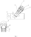
- Fig. 1 is a structural schematic of a surgical robot system according to an embodiment of the invention.
- the surgical robot system includes a slave unit including a patient cart 1, a robotic arm 2, a surgical instrument 3, an endoscope 4 and a cannula 9.
- the patient cart 1 supports all the mechanical mechanisms. Meanwhile, the patient cart 1 is moveable on the ground to allow the slave unit to approach or leave a patient 8.
- the robotic arm 2 with multiple degrees of freedom is mounted on the patient cart 1 and configured to drive the surgical instrument 3 to pivot about a remote center of motion (RCM).
- RCM remote center of motion
- the robotic arm 2 may be adjusted so that the surgical instrument 3 reaches a predetermined target surgical site. That is, the RCM is located around the surgical site by adjusting both the patient cart 1 and the robotic arm 2.
- the surgical instrument 3 is mounted at a terminal end of the robotic arm 2, either fixedly or movably. As an effector of the slave unit, the surgical instrument 3 will eventually enter into the patient's body at the surgical site so as to treat a target lesion in vivo.
- the surgical instrument 3 will move with multiple degrees of freedom around the RCM, and in order to prevent the movements of the surgical instrument 3 from causing damage to the body's surface tissue and to create a sealed environment within the body, the cannula 9 is disposed between the surgical instrument 3 and said surface tissue.
- the cannula 9 is detachably connected with a terminal end of the robotic arm 2 and defines an axis passing through the RCM.
- One end of the surgical instrument 3 is detachably connected to the terminal end of the robotic arm 2, and the other end is inserted through the cannula 9 and distally into the patient's body so as to approach the lesion.
- the surgical instrument 3 can move in synchronization with the cannula 9 around the RCM, while also being able to achieve movement along and/or rotation about the axis thereof within the cannula 9.
- the endoscope 4 is mounted at a terminal end of a different robotic arm 2 from that on which the surgical instrument 3 is installed and is configured to collect image information about the surgical environment.
- the image information may include, but is not limited to, information about tissue around the lesion and that about a posture and position of the surgical instrument 3.
- the endoscope 4 may be communicatively connected to the master unit as detailed below so as to enable real-time display of the information about the surgical environment collected thereby.
- the endoscope 4 may be three-dimensional or not, which is not limited by the present invention.
- the surgical robot system may further include a master unit including an imaging system 5, a master manipulator 6 and an armrest 7.
- a surgeon can monitor motion of the surgical instrument 3 in real time, and accordingly control the subsequent movement of the surgical instrument 3 by manipulating the master manipulator 6.
- the surgeon may sit at a surgical console and, with the aid of the imaging system 5, observe the position and motion of the terminal end of the surgical instrument within the patient's body. Based on the observations, the surgeon can control a subsequent movement of the terminal end by manipulating the master manipulator 6, thus allowing for a minimally invasive operation.
- the surgical instrument 3 may make movements in multi-dimensional space, as required in the surgical procedure, such as pitching, yawing, rotating, opening and closing.
- the armrest 7 can support the surgeon's arm so that the surgeon can maintain a higher comfort when the surgical procedure lasts for a long time.
- the armrest 7 can be raised and lowered to meet various needs of different surgeons.
- the surgical robot system further includes a computing unit 10 communicatively connected to both the master and slave units, for example, by wired or wireless connections.
- the computing unit 10 is responsible for, based on a control strategy, processing sensor data and calculating various data required in the controlling.
- the computing unit 10 detemines a force acting on the cannula 9 from data transmitted by a sensing element 903 (e.g., strain and stress data) and thus determine a force acting on the terminal end of the surgical instrument 3, and then transmit information about the force on the terminal end of the surgical instrument 3 to a force indicator of the master unit, so that the force on the terminal end of the surgical instrument 3 can be known.
- the force indicator may be the imaging system 5, which can display the magnitude and direction of the force on the terminal end of the surgical instrument 3.
- the force indicator may be the master manipulator 6 equipped with a motor. While the surgeon is operating the system, the computing unit 10 may control the motor of the master manipulator 6 based on the information about the force on the terminal end of the surgical instrument 3 and may exert a force acting onto the surgeon. Especially, the control made from the master manipulator 6 to the surgical instrument 3 is basic to the master/slave control loop in the surgical robot system. In order to better simulate the actual circumstances of a surgical procedure, i.e., simulate the force acting on the surgical instrument 3 during the procedure, it is desired that the surgical instrument 3 is able to feed back any force acting on it to the master manipulator 6, i.e., providing the surgical instrument 3 with force feedback capabilities.
- the computing unit 10 can issue a torque command to the motor of the master manipulator 6, to enable the operator to perceive the force acting on the terminal end of the surgical instrument 3. More preferably, the master manipulator 6 may be provided with a vibrator.
- the computing unit 10 can issue a vibration command to the vibrator of the master manipulator 6, notifying the operator about the excessive force on the terminal end of the surgical instrument 3.
- the surgical robot system according to this embodiment is able to measure a radial force on the terminal end of the surgical instrument 3, i.e., a force exerted along a direction perpendicular to an axis of the surgical instrument 3.
- Fig. 2 is a structural schematic of a surgical instrument according to an embodiment of the present invention.
- the surgical instrument 3 includes a power module 301, an instrument shaft 302, a force transmission mechanism and a terminal end effector 303.
- the force transmission mechanism may for example employ wire transmission and be housed in the instrument shaft 302 and connected to both the power module 301 and terminal end effector 303.
- the power module 301 is disposed at a leading end of the instrument shaft 302 (i.e., the end closer to the operator), while the terminal end effector 303 is disposed at a terminal end of the instrument shaft 302 (i.e., the end farther away from the operator).
- the power module 301 is configured to provide a driving force, which is transferred by the force transmission mechanism to the terminal end effector 303, thus enabling the terminal end effector 303 to perform a multi-dimensional rotational motion, an opening/closing action, etc.
- the terminal end effector 303 is configured to perform actions, such as cutting, probing and pinching, to the patient's lesion.
- the present invention is not limited to any particular type of the terminal end effector 303 as it can be scissors, pliers, a probe or the like.
- a coordinate system may be defined for the surgical instrument 3.
- This coordinate system is not limited to the rectangular coordinate system as shown but can alternatively be a cylindrical coordinate system, a polar coordinate system or the like.
- the coordinate system is established with three axes which are X axis, Y axis and Z axis, wherein the Z axis extends along an axis of the instrument shaft 302, X axis is perpendicular to the axis of the instrument shaft 302 and Y axis is determined according to the right-hand rule.
- the terminal end of the surgical instrument 3 i.e., the end equipped with the terminal end effector 303
- the terminal end of the surgical instrument 3 will interact with the patient's tissue generally by applying thereto forces along the three axes.
- the terminal end of the surgical instrument 3 will be subject to the reaction forces which are equal in magnitude but opposite in direction to the acting force along the three axes, in which the reaction forces along the X and Y axes may be obtained by the sensing element 903 and computing unit 10. This will be described in greater detail below.
- the power module 301 may be connected to a proximal end of the instrument shaft 302, and the instrument shaft 302 is received in the cannula 9.
- the instrument shaft 302 is configured to be able to come into point-contact with the cannula 9. Improved accuracy in radial force measurement at the terminal end of the surgical instrument can be obtained by measuring a point-contact force between the cannula 9 and surgical instrument 3.
- Fig. 6 is a structural schematic of a cannula (with a protrusion 902 therein, as indicated by dotted lines) according to an embodiment of the present invention.
- the cannula 9 may include a mount 901 configured to be detachably connected with the terminal end of the robotic arm 2.
- the cannula 9 may also include a protrusion 902 projecting from an inner wall of the cannula 9.
- the sensing element 903 may be attached on the cannula 9.
- the cannula 9 may further include a reference point (not shown, fixed in position relative to the mount 901) located at the RCM.
- Both the protrusion 902 and sensing element 903 may be disposed on the side of the reference point farther away from the mount 901 (i.e., the side thereof farther away from the terminal end of the robotic arm), and the protrusion 902 may be located even farther away than the sensing element 903 from the mount 901, i.e., from the terminal end of the robotic arm.
- the instrument shaft 302 is inserted through the cannula 9, with the protrusion 902 being configured to be able to come into point-contact with the instrument shaft 302.
- the instrument shaft 302 is configured to be coaxial and in a clearance fit with the cannula 9.
- the sensing element 903 may be attached to either an inner surface or an outer surface of the cannula 9.
- an end of the cannula 9 away from the mount 901 i.e., the end on the same side as the protrusion 902 with respect to the reference point
- only one protrusion 902 may be provided, as shown in Fig. 4a , in the form of an annulus.
- a plurality of such protrusions 902, for example, four protrusions 902, may be provided as shown in Figs. 4b and 4c .
- the protrusions 902 may be symmetrically distributed.
- the present invention is not limited to any particular number of protrusions 902.
- the invention is also not limited to any particular shape of the protrusion(s) 902, as long as it is ensured that the instrument shaft 302 can come into point-contact with the cannula 9. Just for this reason, a width of each protrusion 902 along the circumferential direction of the instrument shaft 302 should be made as small as possible.
- point-contact may occur between curved surface of the protrusions 902 and an outer surface of the instrument shaft 302.
- point-contact may occur between flat surfaces of the protrusions 902 and the outer surface of the instrument shaft 302 that is in the form of a circular rod.
- the sensing element 903 is preferably disposed to be closer to the mount 901 (i.e., closer to the terminal end of the robotic arm) than the protrusion(s) 902 is disposed to be.
- the sensing element 903 is disposed on a portion of the cannula between the reference point and protrusion(s) 902 (as shown in Fig. 6 ).
- a plurality of (e.g., three or four) sensing elements 903 may be provided. More preferably, these sensing elements 903 may be symmetrically distributed.
- four sensing elements 903 may be provided, in which two are disposed along the X axis and in symmetry with each other with respect to the Y axis, and the other two are disposed along the Y axis and in symmetry with each other with respect to the X axis.
- Examples of devices that can be used as the sensing elements 903 may include, but not limited to, foil strain gauges, semiconductor resistive strain gauges, piezoelectric sensors, semiconductor pressure sensors, etc.
- Fig. 3 schematically illustrates reaction forces applied by human tissue on the terminal end of the surgical instrument that is inserted through the cannula, in accordance with an embodiment of the invention.
- the terminal end of the surgical instrument 3 may receive a force F x in the +X direction, a force F y in the +Y direction and a force F z in the +Z direction, and the computing unit 10 is configured to determine the radial forces F x and F y or the resultant F xy thereof.
- the instrument shaft 302 deforms and comes into contact with the protrusion 902 on the cannula 9, exerting thereon a contact force, which is sensed by the sensing element 903 on the cannula 9.
- the radial force(s) ( F x and F y , or F xy ) is calculated by the computing unit 10.
- the instrument shaft 302 may deform and stop further deforming upon coming into point-contact with the protrusion 902. Meanwhile, the sensing element 903 will be stretched or compressed due to the axial deformation of the cannula 9 and hence sense the contact force applied by the instrument shaft 302 to the cannula 9, from which the reaction force F m from the cannula 9 (which is the resultant of a component F mx along the X axis and a component F my along the Y axis) can be determined.
- the aforementioned relationship may be mathematically modeled using lengths from a first characteristic point defined at the proximal end of the instrument shaft 302 (i.e., where it is connected to the power module 301) respectively to a second characteristic point defined at a location of the instrument shaft 302 where it is contactable with the protrusion 902 and a third characteristic point defined at the terminal end of the surgical instrument 3.
- the length L1 from the first characteristic point to the second characteristic point and the length L2 from the first characteristic point to the third characteristic point may be both known beforehand.
- the length L2 may be measured beforehand.
- the length L1 will vary with the movement of the surgical instrument 3, it cannot be measured in advance.
- an initial value L1 s of the length L1 can be obtained during initialization of the surgical robot.
- a telescopic joint in the robotic arm 2 drives the surgical instrument 3 to move relative to the cannula 9 along the axis thereof, and the displacement sensor on the telescopic joint can measure in real time a displacement ⁇ L of the surgical instrument 3 from the initial position.
- Fig. 5 schematically illustrates forces acting on the surgical instrument, in accordance with an embodiment of the invention. As shown, a moment M about the first characteristic point on the instrument shaft 302 should be zero as the resultant of:
- F xy L2 + F m L1 0, according to which the radial force F xy acting on the terminal end can be calculated from the known parameters L1 and L2 and F m whose magnitude and direction can be measured by the sensing element 903.
- the force F z acting on the terminal end of the surgical instrument 3 in the Z axis may be determined otherwise.
- the power module 301 may preferably include an axial drive motor for driving the surgical instrument 3 to move axially
- the computing unit 10 may be configured to determine the axial force F z on the terminal end of the surgical instrument 3 based on an output force of the axial drive motor and a reduction ratio of the transmission mechanism.
- the axial drive motor's output force may be calculated from a current follow in the motor or directly measured by a sensor disposed on an output shaft of the motor.
- a coating capable of reducing friction between the instrument shaft 302 and the protrusion 902 may preferably be provided over the outer surface of the instrument shaft 302.
- the coating may be a Teflon coating, which can eliminate undesired signal interference resulting from the sliding friction, ensuring good accuracy in measuring the axial force.
- the second characteristic point may be defined at the terminal end of the cannula 9, and the radial force acting on the terminal end of the surgical instrument can be calculated based on a length relationship accordingly derived from the principles and relationship described in supra in conjunction with the foregoing embodiments.
- the computing unit 10 may employ an existing PLC controller, microcomputer, microprocessor or the like, and one skilled in the art will understand how to implement such a selection based on the disclosure herein in combination with the common general knowledge in the art.
- some embodiments of the present invention provides a surgical robot system including a slave unit and a computing unit.
- the slave unit includes a robotic arm, a surgical instrument, a cannula and a sensing element.
- the sensing element is disposed on the cannula and configured to sense an axial deformation of the cannula
- the computing unit is configured to determine a contact force exerted on the cannula from the sensed axial deformation, as well as a radial force acting on a terminal end of the surgical instrument according to the contact force.
- a protrusion is disposed on an inner wall of the cannula, which is configured to be able to come into point-contact with the surgical instrument, and the computing unit is configured to determine the radial force acting on the terminal end of the surgical instrument based on a point-contact force exerted on the cannula according to the axial deformation sensed by the sensing element.
- the computing unit is configured to determine the radial force acting on the terminal end of the surgical instrument based on a point-contact force exerted on the cannula according to the axial deformation sensed by the sensing element.
- a moment of the supporting force is balanced by that of a radial component (i.e., the aforementioned radial force) of the external force acting on the terminal end of the surgical instrument. Therefore, the radial force on the terminal end of the surgical instrument can be accurately and uniquely determined by measuring the contact force exerted by the cannula on the surgical instrument, while avoiding errors that may arise from variation in the structure of the surgical instrument's terminal end.
- the radial force acting on the terminal end of the surgical instrument can be determined with even higher accuracy by measuring a contact force between the protrusion and the surgical instrument.
- the surgical robot system of the present invention is advantageous in both a simpler force transmission path and higher radial force measurement accuracy. Moreover, the radial force acting on the terminal end of the surgical instrument can be obtained in an easier manner without requiring additional components, providing for lower structural complexity of the surgical instrument and facilitating its assembly. Further, since minor changes are required in the surgical instrument, various existing surgical instruments can be suitably used in the proposed surgical robot system.
Landscapes
- Health & Medical Sciences (AREA)
- Engineering & Computer Science (AREA)
- Life Sciences & Earth Sciences (AREA)
- Surgery (AREA)
- Robotics (AREA)
- Medical Informatics (AREA)
- Public Health (AREA)
- Heart & Thoracic Surgery (AREA)
- Nuclear Medicine, Radiotherapy & Molecular Imaging (AREA)
- Molecular Biology (AREA)
- Animal Behavior & Ethology (AREA)
- General Health & Medical Sciences (AREA)
- Biomedical Technology (AREA)
- Veterinary Medicine (AREA)
- Human Computer Interaction (AREA)
- Mechanical Engineering (AREA)
- Pathology (AREA)
- Manipulator (AREA)
- Surgical Instruments (AREA)
Claims (15)
- Système de robot chirurgical comprenant une unité esclave et une unité de calcul (10), l'unité esclave comprenant un bras robotique (2), un instrument chirurgical (3), une canule (9) et un élément de détection (903),la canule (9) étant configurée pour pouvoir générer un contact ponctuel lorsqu'elle est mise en contact avec l'instrument chirurgical (3),le bras robotique (2) étant configuré pour entraîner l'instrument chirurgical (3) à pivoter autour d'un centre de mouvement distant,la canule (9) étant en liaison rigide amovible avec une extrémité terminale du bras robotique (2), et un axe de la canule (9) s'étendant à travers le centre de mouvement distant,l'instrument chirurgical (3) étant relié de manière amovible à l'extrémité terminale du bras robotique (2) et s'étendant de manière distale à travers la canule (9),l'élément de détection (903) étant disposé sur la canule (9) et configuré pour détecter une déformation axiale de la canule (9) ;l'unité de calcul (10) étant configurée pour déterminer, selon un principe d'équilibre du couple, une force radiale agissant sur une extrémité terminale de l'instrument chirurgical (3) sur la base d'une force agissant sur la canule (9) qui résulte du contact ponctuel et qui est détectée et déterminée par l'élément de détection (903).
- Système de robot chirurgical selon la revendication 1, une protubérance (902) étant prévue sur une paroi interne de la canule (9), et la protubérance (902) étant configurée pour pouvoir générer le contact ponctuel lorsqu'elle est mise en contact avec l'instrument chirurgical (3),la canule (9) comprenant un point de référence situé au centre de mouvement distant, la protubérance (902) et l'élément de détection (903) étant tous deux disposés d'un côté du point de référence plus éloigné de l'extrémité terminale du bras robotique (2), etl'unité de calcul (10) étant configurée pour déterminer la force radiale agissant sur l'extrémité terminale de l'instrument chirurgical (3) sur la base d'une force agissant sur la canule (9) à un emplacement du point de contact détecté et déterminé par l'élément de détection (903).
- Système de robot chirurgical selon la revendication 2, une protubérance (902) étant prévue sur la paroi interne de la canule (9) ; ou une pluralité de protubérances (902) étant prévues sur la paroi interne de la canule (9) et réparties symétriquement sur celle-ci.
- Système de robot chirurgical selon la revendication 2, l'élément de détection (903) étant disposé de manière à être plus proche de l'extrémité terminale du bras robotique (2) que ne l'est la protubérance (902).
- Système de robot chirurgical selon l'une quelconque des revendications 1 à 4, une pluralité d'éléments de détection (903) étant répartis symétriquement sur une surface intérieure et/ou une surface extérieure de la canule (9).
- Système de robot chirurgical selon la revendication 1 ou 2, la canule (9) comprenant une monture (901) configurée pour se relier de manière amovible avec l'extrémité terminale du bras robotique (2).
- Système de robot chirurgical selon la revendication 1 ou 2, la canule (9) étant configurée pour être coaxiale ou dans un ajustement de dégagement avec l'instrument chirurgical (3).
- Système de robot chirurgical selon la revendication 1, l'instrument chirurgical (3) comprenant un module de puissance (301), un arbre d'instrument (302), un premier point caractéristique, un deuxième point caractéristique et un troisième point caractéristique ; le module de puissance (301) étant relié à une extrémité proximale de l'arbre d'instrument (302), l'arbre d'instrument (302) étant configuré pour pouvoir générer le contact ponctuel lorsqu'il est mis en contact avec la canule (9), le premier point caractéristique étant défini à un emplacement où l'arbre d'instrument (302) est relié au module de puissance (301), le deuxième point caractéristique étant défini à un emplacement de l'arbre d'instrument (302) en correspondance avec une extrémité terminale de la canule (9), le troisième point caractéristique étant défini à l'extrémité terminale de l'instrument chirurgical (3), et la force radiale agissant sur le troisième point caractéristique pouvant être déterminée par l'unité de calcul (10) sur la base d'une force agissant sur le deuxième point caractéristique, d'une distance entre le premier point caractéristique et le deuxième point caractéristique, et d'une distance entre le premier point caractéristique et le troisième point caractéristique.
- Système de robot chirurgical selon la revendication 2, l'instrument chirurgical (3) comprenant un module de puissance (301), un arbre d'instrument (302), un premier point caractéristique, un deuxième point caractéristique et un troisième point caractéristique ; le module de puissance (301) étant relié à une extrémité proximale de l'arbre d'instrument (302), l'arbre d'instrument (302) étant configuré pour pouvoir générer le contact ponctuel lorsqu'il est mis en contact avec la protubérance (902), le premier point caractéristique étant défini à un emplacement où l'arbre d'instrument (302) est relié au module de puissance (301), le deuxième point caractéristique étant défini à un emplacement où la protubérance (902) peut être mise en contact avec l'arbre d'instrument (302), le troisième point caractéristique étant défini à l'extrémité terminale de l'instrument chirurgical (3), et la force radiale agissant sur le troisième point caractéristique pouvant être déterminée par l'unité de calcul (10) sur la base d'une force agissant sur le deuxième point caractéristique, d'une distance entre le premier point caractéristique et le deuxième point caractéristique, et d'une distance entre le premier point caractéristique et le troisième point caractéristique.
- Système de robot chirurgical selon la revendication 8 ou 9, la distance entre le premier point caractéristique et le deuxième point caractéristique étant obtenue sur la base d'une valeur initiale de la distance entre le premier point caractéristique et le deuxième point caractéristique déterminée lors de l'initialisation du système de robot chirurgical, et d'un déplacement de l'instrument chirurgical (3) le long d'un axe de la canule (9) par rapport à une position initiale de l'instrument chirurgical (3) déterminée lors de l'initialisation du système de robot chirurgical.
- Système de robot chirurgical selon la revendication 1 ou 2, l'instrument chirurgical (3) comprenant un module de puissance (301) et un mécanisme de transmission configuré pour transférer une force de sortie du module de puissance (301) à l'extrémité terminale de l'instrument chirurgical (3), le module de puissance (301) comprenant un moteur d'entraînement axial configuré pour entraîner l'instrument chirurgical (3) à se déplacer axialement, et l'unité de calcul (10) étant configurée pour déterminer une force axiale agissant sur l'extrémité terminale de l'instrument chirurgical (3) sur la base d'une force de sortie du moteur d'entraînement axial et d'un rapport de réduction du mécanisme de transmission.
- Système de robot chirurgical selon la revendication 11, la force de sortie du moteur d'entraînement axial étant calculable à partir d'un courant électrique circulant dans le moteur d'entraînement axial ou mesurable par un capteur disposé sur un arbre de sortie du moteur d'entraînement axial.
- Système de robot chirurgical selon la revendication 11, un revêtement étant fourni sur une surface extérieure de l'instrument chirurgical (3), pour réduire la friction entre l'instrument chirurgical (3) et la canule (9).
- Système de robot chirurgical selon la revendication 1 ou 2, comprenant en outre une unité maître comprenant un indicateur de force configuré pour permettre à la force radiale agissant sur l'extrémité terminale de l'instrument chirurgical (3) d'être perçue.
- Système de robot chirurgical selon la revendication 14, l'indicateur de force étant un manipulateur principal (6) doté d'un moteur relié de manière communicative à l'unité de calcul (10), ou l'indicateur de force étant un système d'imagerie.
Applications Claiming Priority (3)
| Application Number | Priority Date | Filing Date | Title |
|---|---|---|---|
| CN201710854319 | 2017-09-20 | ||
| CN201710865638.5A CN108210078B (zh) | 2017-09-22 | 2017-09-22 | 手术机器人系统 |
| PCT/CN2018/098500 WO2019056871A1 (fr) | 2017-09-20 | 2018-08-03 | Système de robot chirurgical |
Publications (3)
| Publication Number | Publication Date |
|---|---|
| EP3685787A1 EP3685787A1 (fr) | 2020-07-29 |
| EP3685787A4 EP3685787A4 (fr) | 2020-11-18 |
| EP3685787B1 true EP3685787B1 (fr) | 2023-10-04 |
Family
ID=65811078
Family Applications (1)
| Application Number | Title | Priority Date | Filing Date |
|---|---|---|---|
| EP18859051.7A Active EP3685787B1 (fr) | 2017-09-20 | 2018-08-03 | Système de robot chirurgical |
Country Status (6)
| Country | Link |
|---|---|
| US (1) | US11478316B2 (fr) |
| EP (1) | EP3685787B1 (fr) |
| JP (1) | JP6931420B2 (fr) |
| BR (1) | BR112020004420A2 (fr) |
| RU (1) | RU2741469C1 (fr) |
| WO (1) | WO2019056871A1 (fr) |
Families Citing this family (16)
| Publication number | Priority date | Publication date | Assignee | Title |
|---|---|---|---|---|
| US11497566B2 (en) * | 2018-10-26 | 2022-11-15 | Biosense Webster (Israel) Ltd. | Loose mode for robot |
| JP6867654B2 (ja) * | 2019-03-15 | 2021-05-12 | リバーフィールド株式会社 | 医用ロボットシステムの力覚表示装置および力覚表示方法 |
| CN110215287A (zh) * | 2019-03-29 | 2019-09-10 | 上海联影医疗科技有限公司 | 一种主从式医疗操控系统 |
| CN111870288B (zh) * | 2019-09-10 | 2021-11-02 | 深圳市精锋医疗科技有限公司 | 手术机器人及其机械臂的控制方法、控制装置 |
| JP6801901B1 (ja) | 2019-10-17 | 2020-12-16 | リバーフィールド株式会社 | 手術ロボットシステム、外力推定装置、および、プログラム |
| US11529734B2 (en) * | 2019-10-31 | 2022-12-20 | Verb Surgical Inc. | Systems and methods for visual sensing of and docking with a trocar |
| US11660081B2 (en) | 2019-11-27 | 2023-05-30 | Medtech S.A. | Surgical instrument retainer device |
| US20220022915A1 (en) * | 2020-07-22 | 2022-01-27 | Covidien Lp | Trocar system with force sensing |
| CN112155711B (zh) * | 2020-09-10 | 2025-04-25 | 河南省人民医院 | 方向校正环、椎弓根钉植入辅助校正系统及辅助植入系统 |
| CN114905478B (zh) * | 2021-02-08 | 2024-09-17 | 腾讯科技(深圳)有限公司 | 双边遥操作系统及控制方法 |
| US20220257320A1 (en) * | 2021-02-18 | 2022-08-18 | Mazor Robotics Ltd. | Systems, devices, and methods for tool skive avoidance |
| CN114533269B (zh) * | 2021-09-13 | 2023-10-31 | 广西大学 | 一种手术机器人rcm定位机构 |
| CN115778548A (zh) * | 2022-11-07 | 2023-03-14 | 上海微创医疗机器人(集团)股份有限公司 | 力感知连接结构、手术机器人及手术系统 |
| CN116602770B (zh) * | 2023-05-23 | 2026-03-10 | 成都博恩思医学机器人有限公司 | 一种机器人系统及其手术机器人 |
| CN117796914B (zh) * | 2024-03-01 | 2024-06-21 | 科弛医疗科技(北京)有限公司 | 器械驱动盒、手术机器人、以及零位检测方法 |
| CN117838304B (zh) * | 2024-03-01 | 2024-06-25 | 科弛医疗科技(北京)有限公司 | 零位检测结构和检测方法、器械驱动盒以及手术机器人 |
Citations (7)
| Publication number | Priority date | Publication date | Assignee | Title |
|---|---|---|---|---|
| JPH05154094A (ja) * | 1991-12-03 | 1993-06-22 | Olympus Optical Co Ltd | 気腹装置 |
| US5395331A (en) * | 1992-04-27 | 1995-03-07 | Minnesota Mining And Manufacturing Company | Retrograde coronary sinus catheter having a ribbed balloon |
| US7357774B2 (en) * | 1996-12-12 | 2008-04-15 | Intuitive Surgical Inc. | Multi-component telepresence system and method |
| US7727244B2 (en) * | 1997-11-21 | 2010-06-01 | Intuitive Surgical Operation, Inc. | Sterile surgical drape |
| KR101413406B1 (ko) * | 2013-04-01 | 2014-06-27 | 한국과학기술원 | 접촉 토크 측정 장치, 수술 로봇 및 이를 구비하는 수술 로봇 시스템 |
| WO2016018815A1 (fr) * | 2014-07-29 | 2016-02-04 | Intuitive Surgical Operations, Inc. | Canule comprenant des capteurs pour mesurer des forces de paroi corporelle de patient |
| WO2016064632A1 (fr) * | 2014-10-24 | 2016-04-28 | Covidien Lp | Ports d'accès de système chirurgical robotique de détection |
Family Cites Families (19)
| Publication number | Priority date | Publication date | Assignee | Title |
|---|---|---|---|---|
| US5623582A (en) | 1994-07-14 | 1997-04-22 | Immersion Human Interface Corporation | Computer interface or control input device for laparoscopic surgical instrument and other elongated mechanical objects |
| EP2266466B1 (fr) | 1995-06-07 | 2015-04-22 | SRI International | Manipulateur chirurgical pour un système télérobotique |
| US8182469B2 (en) * | 1997-11-21 | 2012-05-22 | Intuitive Surgical Operations, Inc. | Surgical accessory clamp and method |
| JP2002159509A (ja) * | 2000-08-09 | 2002-06-04 | Japan Science & Technology Corp | 躰腔鏡下外科手術操作器の先端負荷力の検出方法およびその装置 |
| US20070018958A1 (en) | 2003-10-24 | 2007-01-25 | Tavakoli Seyed M | Force reflective robotic control system and minimally invasive surgical device |
| ATE355023T1 (de) | 2004-01-07 | 2006-03-15 | Univ Paris Curie | Trocar device for the passage of a surgical instrument |
| US8375808B2 (en) * | 2005-12-30 | 2013-02-19 | Intuitive Surgical Operations, Inc. | Force sensing for surgical instruments |
| US8496647B2 (en) * | 2007-12-18 | 2013-07-30 | Intuitive Surgical Operations, Inc. | Ribbed force sensor |
| US7930065B2 (en) | 2005-12-30 | 2011-04-19 | Intuitive Surgical Operations, Inc. | Robotic surgery system including position sensors using fiber bragg gratings |
| KR101296220B1 (ko) | 2005-12-30 | 2013-08-13 | 인튜어티브 서지컬 인코포레이티드 | 모듈식 힘센서 |
| KR101460812B1 (ko) | 2006-10-04 | 2014-11-11 | 아스렉스, 인코퍼레이티드 | 확장 캐뉼러 |
| EP1915963A1 (fr) * | 2006-10-25 | 2008-04-30 | The European Atomic Energy Community (EURATOM), represented by the European Commission | Estimation de la force pour un systeme d'intervention chirurgicale robotisée à effraction minimale |
| US9895813B2 (en) * | 2008-03-31 | 2018-02-20 | Intuitive Surgical Operations, Inc. | Force and torque sensing in a surgical robot setup arm |
| KR20120030174A (ko) | 2010-09-17 | 2012-03-28 | 삼성전자주식회사 | 촉각 피드백을 제공하는 수술 로봇 시스템 및 수술 장치, 그리고 그의 촉각 피드백 제공 방법 |
| RU122326U1 (ru) * | 2012-01-18 | 2012-11-27 | Олег Владимирович Галимов | Роботическая система для проведения эндовидеохирургических операций |
| JP6037964B2 (ja) | 2013-07-26 | 2016-12-07 | オリンパス株式会社 | マニピュレータシステム |
| US10548630B2 (en) * | 2014-02-11 | 2020-02-04 | Vanderbilt University | System, method, and apparatus for configuration, design, and operation of an active cannula robot |
| WO2017020081A1 (fr) | 2015-08-03 | 2017-02-09 | Deakin University | Appareil, système et procédé de commande de mouvement de manipulateur robotique |
| CN108210078B (zh) | 2017-09-22 | 2020-11-27 | 微创(上海)医疗机器人有限公司 | 手术机器人系统 |
-
2018
- 2018-08-03 EP EP18859051.7A patent/EP3685787B1/fr active Active
- 2018-08-03 RU RU2020113016A patent/RU2741469C1/ru active
- 2018-08-03 JP JP2020516408A patent/JP6931420B2/ja active Active
- 2018-08-03 BR BR112020004420-2A patent/BR112020004420A2/pt not_active Application Discontinuation
- 2018-08-03 WO PCT/CN2018/098500 patent/WO2019056871A1/fr not_active Ceased
- 2018-08-03 US US16/646,779 patent/US11478316B2/en active Active
Patent Citations (9)
| Publication number | Priority date | Publication date | Assignee | Title |
|---|---|---|---|---|
| JPH05154094A (ja) * | 1991-12-03 | 1993-06-22 | Olympus Optical Co Ltd | 気腹装置 |
| US5395331A (en) * | 1992-04-27 | 1995-03-07 | Minnesota Mining And Manufacturing Company | Retrograde coronary sinus catheter having a ribbed balloon |
| US7357774B2 (en) * | 1996-12-12 | 2008-04-15 | Intuitive Surgical Inc. | Multi-component telepresence system and method |
| EP1015068B1 (fr) * | 1996-12-12 | 2011-09-07 | Intuitive Surgical Operations, Inc. | Système de télépresence multicomposant et procédé de preparation correspondant |
| US7727244B2 (en) * | 1997-11-21 | 2010-06-01 | Intuitive Surgical Operation, Inc. | Sterile surgical drape |
| KR101413406B1 (ko) * | 2013-04-01 | 2014-06-27 | 한국과학기술원 | 접촉 토크 측정 장치, 수술 로봇 및 이를 구비하는 수술 로봇 시스템 |
| WO2016018815A1 (fr) * | 2014-07-29 | 2016-02-04 | Intuitive Surgical Operations, Inc. | Canule comprenant des capteurs pour mesurer des forces de paroi corporelle de patient |
| EP3179936B1 (fr) * | 2014-07-29 | 2019-06-26 | Intuitive Surgical Operations, Inc. | Canule comprenant des capteurs pour mesurer des forces de paroi corporelle de patient |
| WO2016064632A1 (fr) * | 2014-10-24 | 2016-04-28 | Covidien Lp | Ports d'accès de système chirurgical robotique de détection |
Also Published As
| Publication number | Publication date |
|---|---|
| US11478316B2 (en) | 2022-10-25 |
| JP6931420B2 (ja) | 2021-09-01 |
| JP2020534078A (ja) | 2020-11-26 |
| BR112020004420A2 (pt) | 2020-09-08 |
| RU2741469C1 (ru) | 2021-01-26 |
| EP3685787A1 (fr) | 2020-07-29 |
| EP3685787A4 (fr) | 2020-11-18 |
| WO2019056871A1 (fr) | 2019-03-28 |
| US20200289227A1 (en) | 2020-09-17 |
Similar Documents
| Publication | Publication Date | Title |
|---|---|---|
| EP3685787B1 (fr) | Système de robot chirurgical | |
| JP7127128B2 (ja) | 手術ロボットシステム及びその手術器具 | |
| CN108210078B (zh) | 手术机器人系统 | |
| US12496148B2 (en) | Surgery supporting apparatus for controlling motion of robot arm | |
| CN107961078B (zh) | 手术机器人系统及其手术器械 | |
| EP3766449B1 (fr) | Système de robot chirurgical et instrument chirurgical associé | |
| KR102190298B1 (ko) | 수술 로봇 장치와 수술 로봇 장치의 구동 방법 | |
| JP6801901B1 (ja) | 手術ロボットシステム、外力推定装置、および、プログラム | |
| US20240130812A1 (en) | Systems and methods for control of a surgical system | |
| WO2020231785A1 (fr) | Système et procédé de commande de préhension et de distribution d'énergie | |
| WO2022196037A1 (fr) | Dispositif de mesure de force, procédé de mesure de force, dispositif chirurgical et système chirurgical | |
| WO2024081300A1 (fr) | Systèmes de rétroaction haptique de système chirurgical | |
| CN115957006B (zh) | 基于姿态确定可形变机械臂的外部受力的方法及机器人系统 | |
| Guo et al. | Robotic catheter operating systems for endovascular neurosurgery |
Legal Events
| Date | Code | Title | Description |
|---|---|---|---|
| STAA | Information on the status of an ep patent application or granted ep patent |
Free format text: STATUS: THE INTERNATIONAL PUBLICATION HAS BEEN MADE |
|
| PUAI | Public reference made under article 153(3) epc to a published international application that has entered the european phase |
Free format text: ORIGINAL CODE: 0009012 |
|
| STAA | Information on the status of an ep patent application or granted ep patent |
Free format text: STATUS: REQUEST FOR EXAMINATION WAS MADE |
|
| 17P | Request for examination filed |
Effective date: 20200313 |
|
| AK | Designated contracting states |
Kind code of ref document: A1 Designated state(s): AL AT BE BG CH CY CZ DE DK EE ES FI FR GB GR HR HU IE IS IT LI LT LU LV MC MK MT NL NO PL PT RO RS SE SI SK SM TR |
|
| AX | Request for extension of the european patent |
Extension state: BA ME |
|
| A4 | Supplementary search report drawn up and despatched |
Effective date: 20201021 |
|
| RIC1 | Information provided on ipc code assigned before grant |
Ipc: A61B 17/34 20060101ALI20201015BHEP Ipc: A61B 90/00 20160101ALI20201015BHEP Ipc: A61B 17/00 20060101ALI20201015BHEP Ipc: A61B 34/37 20160101AFI20201015BHEP Ipc: A61B 34/00 20160101ALI20201015BHEP |
|
| DAV | Request for validation of the european patent (deleted) | ||
| DAX | Request for extension of the european patent (deleted) | ||
| RAP3 | Party data changed (applicant data changed or rights of an application transferred) |
Owner name: SHANGAI MICROPORT MEDBOT (GROUP) CO., LTD. |
|
| RAP3 | Party data changed (applicant data changed or rights of an application transferred) |
Owner name: SHANGAI MICROPORT MEDBOT (GROUP) CO., LTD. |
|
| GRAP | Despatch of communication of intention to grant a patent |
Free format text: ORIGINAL CODE: EPIDOSNIGR1 |
|
| STAA | Information on the status of an ep patent application or granted ep patent |
Free format text: STATUS: GRANT OF PATENT IS INTENDED |
|
| RIC1 | Information provided on ipc code assigned before grant |
Ipc: A61B 34/00 20160101ALI20221021BHEP Ipc: A61B 17/34 20060101ALI20221021BHEP Ipc: A61B 17/00 20060101ALI20221021BHEP Ipc: A61B 90/00 20160101ALI20221021BHEP Ipc: A61B 34/37 20160101AFI20221021BHEP |
|
| INTG | Intention to grant announced |
Effective date: 20221125 |
|
| GRAS | Grant fee paid |
Free format text: ORIGINAL CODE: EPIDOSNIGR3 |
|
| GRAJ | Information related to disapproval of communication of intention to grant by the applicant or resumption of examination proceedings by the epo deleted |
Free format text: ORIGINAL CODE: EPIDOSDIGR1 |
|
| GRAL | Information related to payment of fee for publishing/printing deleted |
Free format text: ORIGINAL CODE: EPIDOSDIGR3 |
|
| STAA | Information on the status of an ep patent application or granted ep patent |
Free format text: STATUS: REQUEST FOR EXAMINATION WAS MADE |
|
| GRAP | Despatch of communication of intention to grant a patent |
Free format text: ORIGINAL CODE: EPIDOSNIGR1 |
|
| STAA | Information on the status of an ep patent application or granted ep patent |
Free format text: STATUS: GRANT OF PATENT IS INTENDED |
|
| INTC | Intention to grant announced (deleted) | ||
| INTG | Intention to grant announced |
Effective date: 20230421 |
|
| GRAS | Grant fee paid |
Free format text: ORIGINAL CODE: EPIDOSNIGR3 |
|
| GRAA | (expected) grant |
Free format text: ORIGINAL CODE: 0009210 |
|
| STAA | Information on the status of an ep patent application or granted ep patent |
Free format text: STATUS: THE PATENT HAS BEEN GRANTED |
|
| AK | Designated contracting states |
Kind code of ref document: B1 Designated state(s): AL AT BE BG CH CY CZ DE DK EE ES FI FR GB GR HR HU IE IS IT LI LT LU LV MC MK MT NL NO PL PT RO RS SE SI SK SM TR |
|
| REG | Reference to a national code |
Ref country code: GB Ref legal event code: FG4D |
|
| REG | Reference to a national code |
Ref country code: CH Ref legal event code: EP |
|
| REG | Reference to a national code |
Ref country code: IE Ref legal event code: FG4D |
|
| REG | Reference to a national code |
Ref country code: DE Ref legal event code: R096 Ref document number: 602018058881 Country of ref document: DE |
|
| REG | Reference to a national code |
Ref country code: LT Ref legal event code: MG9D |
|
| REG | Reference to a national code |
Ref country code: NL Ref legal event code: MP Effective date: 20231004 |
|
| REG | Reference to a national code |
Ref country code: AT Ref legal event code: MK05 Ref document number: 1616921 Country of ref document: AT Kind code of ref document: T Effective date: 20231004 |
|
| PG25 | Lapsed in a contracting state [announced via postgrant information from national office to epo] |
Ref country code: NL Free format text: LAPSE BECAUSE OF FAILURE TO SUBMIT A TRANSLATION OF THE DESCRIPTION OR TO PAY THE FEE WITHIN THE PRESCRIBED TIME-LIMIT Effective date: 20231004 |
|
| PG25 | Lapsed in a contracting state [announced via postgrant information from national office to epo] |
Ref country code: GR Free format text: LAPSE BECAUSE OF FAILURE TO SUBMIT A TRANSLATION OF THE DESCRIPTION OR TO PAY THE FEE WITHIN THE PRESCRIBED TIME-LIMIT Effective date: 20240105 |
|
| PG25 | Lapsed in a contracting state [announced via postgrant information from national office to epo] |
Ref country code: IS Free format text: LAPSE BECAUSE OF FAILURE TO SUBMIT A TRANSLATION OF THE DESCRIPTION OR TO PAY THE FEE WITHIN THE PRESCRIBED TIME-LIMIT Effective date: 20240204 |
|
| PG25 | Lapsed in a contracting state [announced via postgrant information from national office to epo] |
Ref country code: LT Free format text: LAPSE BECAUSE OF FAILURE TO SUBMIT A TRANSLATION OF THE DESCRIPTION OR TO PAY THE FEE WITHIN THE PRESCRIBED TIME-LIMIT Effective date: 20231004 |
|
| PG25 | Lapsed in a contracting state [announced via postgrant information from national office to epo] |
Ref country code: AT Free format text: LAPSE BECAUSE OF FAILURE TO SUBMIT A TRANSLATION OF THE DESCRIPTION OR TO PAY THE FEE WITHIN THE PRESCRIBED TIME-LIMIT Effective date: 20231004 |
|
| PG25 | Lapsed in a contracting state [announced via postgrant information from national office to epo] |
Ref country code: ES Free format text: LAPSE BECAUSE OF FAILURE TO SUBMIT A TRANSLATION OF THE DESCRIPTION OR TO PAY THE FEE WITHIN THE PRESCRIBED TIME-LIMIT Effective date: 20231004 |
|
| PG25 | Lapsed in a contracting state [announced via postgrant information from national office to epo] |
Ref country code: LT Free format text: LAPSE BECAUSE OF FAILURE TO SUBMIT A TRANSLATION OF THE DESCRIPTION OR TO PAY THE FEE WITHIN THE PRESCRIBED TIME-LIMIT Effective date: 20231004 Ref country code: IS Free format text: LAPSE BECAUSE OF FAILURE TO SUBMIT A TRANSLATION OF THE DESCRIPTION OR TO PAY THE FEE WITHIN THE PRESCRIBED TIME-LIMIT Effective date: 20240204 Ref country code: GR Free format text: LAPSE BECAUSE OF FAILURE TO SUBMIT A TRANSLATION OF THE DESCRIPTION OR TO PAY THE FEE WITHIN THE PRESCRIBED TIME-LIMIT Effective date: 20240105 Ref country code: ES Free format text: LAPSE BECAUSE OF FAILURE TO SUBMIT A TRANSLATION OF THE DESCRIPTION OR TO PAY THE FEE WITHIN THE PRESCRIBED TIME-LIMIT Effective date: 20231004 Ref country code: BG Free format text: LAPSE BECAUSE OF FAILURE TO SUBMIT A TRANSLATION OF THE DESCRIPTION OR TO PAY THE FEE WITHIN THE PRESCRIBED TIME-LIMIT Effective date: 20240104 Ref country code: AT Free format text: LAPSE BECAUSE OF FAILURE TO SUBMIT A TRANSLATION OF THE DESCRIPTION OR TO PAY THE FEE WITHIN THE PRESCRIBED TIME-LIMIT Effective date: 20231004 Ref country code: PT Free format text: LAPSE BECAUSE OF FAILURE TO SUBMIT A TRANSLATION OF THE DESCRIPTION OR TO PAY THE FEE WITHIN THE PRESCRIBED TIME-LIMIT Effective date: 20240205 |
|
| PG25 | Lapsed in a contracting state [announced via postgrant information from national office to epo] |
Ref country code: SE Free format text: LAPSE BECAUSE OF FAILURE TO SUBMIT A TRANSLATION OF THE DESCRIPTION OR TO PAY THE FEE WITHIN THE PRESCRIBED TIME-LIMIT Effective date: 20231004 Ref country code: RS Free format text: LAPSE BECAUSE OF FAILURE TO SUBMIT A TRANSLATION OF THE DESCRIPTION OR TO PAY THE FEE WITHIN THE PRESCRIBED TIME-LIMIT Effective date: 20231004 Ref country code: PL Free format text: LAPSE BECAUSE OF FAILURE TO SUBMIT A TRANSLATION OF THE DESCRIPTION OR TO PAY THE FEE WITHIN THE PRESCRIBED TIME-LIMIT Effective date: 20231004 Ref country code: NO Free format text: LAPSE BECAUSE OF FAILURE TO SUBMIT A TRANSLATION OF THE DESCRIPTION OR TO PAY THE FEE WITHIN THE PRESCRIBED TIME-LIMIT Effective date: 20240104 Ref country code: LV Free format text: LAPSE BECAUSE OF FAILURE TO SUBMIT A TRANSLATION OF THE DESCRIPTION OR TO PAY THE FEE WITHIN THE PRESCRIBED TIME-LIMIT Effective date: 20231004 Ref country code: HR Free format text: LAPSE BECAUSE OF FAILURE TO SUBMIT A TRANSLATION OF THE DESCRIPTION OR TO PAY THE FEE WITHIN THE PRESCRIBED TIME-LIMIT Effective date: 20231004 |
|
| REG | Reference to a national code |
Ref country code: DE Ref legal event code: R097 Ref document number: 602018058881 Country of ref document: DE |
|
| PG25 | Lapsed in a contracting state [announced via postgrant information from national office to epo] |
Ref country code: DK Free format text: LAPSE BECAUSE OF FAILURE TO SUBMIT A TRANSLATION OF THE DESCRIPTION OR TO PAY THE FEE WITHIN THE PRESCRIBED TIME-LIMIT Effective date: 20231004 |
|
| PG25 | Lapsed in a contracting state [announced via postgrant information from national office to epo] |
Ref country code: CZ Free format text: LAPSE BECAUSE OF FAILURE TO SUBMIT A TRANSLATION OF THE DESCRIPTION OR TO PAY THE FEE WITHIN THE PRESCRIBED TIME-LIMIT Effective date: 20231004 |
|
| PG25 | Lapsed in a contracting state [announced via postgrant information from national office to epo] |
Ref country code: SK Free format text: LAPSE BECAUSE OF FAILURE TO SUBMIT A TRANSLATION OF THE DESCRIPTION OR TO PAY THE FEE WITHIN THE PRESCRIBED TIME-LIMIT Effective date: 20231004 |
|
| PG25 | Lapsed in a contracting state [announced via postgrant information from national office to epo] |
Ref country code: SM Free format text: LAPSE BECAUSE OF FAILURE TO SUBMIT A TRANSLATION OF THE DESCRIPTION OR TO PAY THE FEE WITHIN THE PRESCRIBED TIME-LIMIT Effective date: 20231004 Ref country code: SK Free format text: LAPSE BECAUSE OF FAILURE TO SUBMIT A TRANSLATION OF THE DESCRIPTION OR TO PAY THE FEE WITHIN THE PRESCRIBED TIME-LIMIT Effective date: 20231004 Ref country code: RO Free format text: LAPSE BECAUSE OF FAILURE TO SUBMIT A TRANSLATION OF THE DESCRIPTION OR TO PAY THE FEE WITHIN THE PRESCRIBED TIME-LIMIT Effective date: 20231004 Ref country code: IT Free format text: LAPSE BECAUSE OF FAILURE TO SUBMIT A TRANSLATION OF THE DESCRIPTION OR TO PAY THE FEE WITHIN THE PRESCRIBED TIME-LIMIT Effective date: 20231004 Ref country code: EE Free format text: LAPSE BECAUSE OF FAILURE TO SUBMIT A TRANSLATION OF THE DESCRIPTION OR TO PAY THE FEE WITHIN THE PRESCRIBED TIME-LIMIT Effective date: 20231004 Ref country code: DK Free format text: LAPSE BECAUSE OF FAILURE TO SUBMIT A TRANSLATION OF THE DESCRIPTION OR TO PAY THE FEE WITHIN THE PRESCRIBED TIME-LIMIT Effective date: 20231004 Ref country code: CZ Free format text: LAPSE BECAUSE OF FAILURE TO SUBMIT A TRANSLATION OF THE DESCRIPTION OR TO PAY THE FEE WITHIN THE PRESCRIBED TIME-LIMIT Effective date: 20231004 |
|
| PLBE | No opposition filed within time limit |
Free format text: ORIGINAL CODE: 0009261 |
|
| STAA | Information on the status of an ep patent application or granted ep patent |
Free format text: STATUS: NO OPPOSITION FILED WITHIN TIME LIMIT |
|
| 26N | No opposition filed |
Effective date: 20240705 |
|
| PG25 | Lapsed in a contracting state [announced via postgrant information from national office to epo] |
Ref country code: SI Free format text: LAPSE BECAUSE OF FAILURE TO SUBMIT A TRANSLATION OF THE DESCRIPTION OR TO PAY THE FEE WITHIN THE PRESCRIBED TIME-LIMIT Effective date: 20231004 |
|
| PG25 | Lapsed in a contracting state [announced via postgrant information from national office to epo] |
Ref country code: SI Free format text: LAPSE BECAUSE OF FAILURE TO SUBMIT A TRANSLATION OF THE DESCRIPTION OR TO PAY THE FEE WITHIN THE PRESCRIBED TIME-LIMIT Effective date: 20231004 |
|
| REG | Reference to a national code |
Ref country code: CH Ref legal event code: PL |
|
| PG25 | Lapsed in a contracting state [announced via postgrant information from national office to epo] |
Ref country code: LU Free format text: LAPSE BECAUSE OF NON-PAYMENT OF DUE FEES Effective date: 20240803 |
|
| GBPC | Gb: european patent ceased through non-payment of renewal fee |
Effective date: 20240803 |
|
| PG25 | Lapsed in a contracting state [announced via postgrant information from national office to epo] |
Ref country code: MC Free format text: LAPSE BECAUSE OF FAILURE TO SUBMIT A TRANSLATION OF THE DESCRIPTION OR TO PAY THE FEE WITHIN THE PRESCRIBED TIME-LIMIT Effective date: 20231004 Ref country code: CH Free format text: LAPSE BECAUSE OF NON-PAYMENT OF DUE FEES Effective date: 20240831 |
|
| REG | Reference to a national code |
Ref country code: BE Ref legal event code: MM Effective date: 20240831 |
|
| PG25 | Lapsed in a contracting state [announced via postgrant information from national office to epo] |
Ref country code: GB Free format text: LAPSE BECAUSE OF NON-PAYMENT OF DUE FEES Effective date: 20240803 |
|
| PG25 | Lapsed in a contracting state [announced via postgrant information from national office to epo] |
Ref country code: BE Free format text: LAPSE BECAUSE OF NON-PAYMENT OF DUE FEES Effective date: 20240831 |
|
| PG25 | Lapsed in a contracting state [announced via postgrant information from national office to epo] |
Ref country code: IE Free format text: LAPSE BECAUSE OF NON-PAYMENT OF DUE FEES Effective date: 20240803 |
|
| PG25 | Lapsed in a contracting state [announced via postgrant information from national office to epo] |
Ref country code: FI Free format text: LAPSE BECAUSE OF FAILURE TO SUBMIT A TRANSLATION OF THE DESCRIPTION OR TO PAY THE FEE WITHIN THE PRESCRIBED TIME-LIMIT Effective date: 20231004 |
|
| PGFP | Annual fee paid to national office [announced via postgrant information from national office to epo] |
Ref country code: DE Payment date: 20250820 Year of fee payment: 8 |
|
| PGFP | Annual fee paid to national office [announced via postgrant information from national office to epo] |
Ref country code: FR Payment date: 20250828 Year of fee payment: 8 |
|
| PG25 | Lapsed in a contracting state [announced via postgrant information from national office to epo] |
Ref country code: CY Free format text: LAPSE BECAUSE OF FAILURE TO SUBMIT A TRANSLATION OF THE DESCRIPTION OR TO PAY THE FEE WITHIN THE PRESCRIBED TIME-LIMIT; INVALID AB INITIO Effective date: 20180803 |
|
| PG25 | Lapsed in a contracting state [announced via postgrant information from national office to epo] |
Ref country code: HU Free format text: LAPSE BECAUSE OF FAILURE TO SUBMIT A TRANSLATION OF THE DESCRIPTION OR TO PAY THE FEE WITHIN THE PRESCRIBED TIME-LIMIT; INVALID AB INITIO Effective date: 20180803 |