EP3685966A2 - Couvercle de batterie et outil électrique doté d'un couvercle de batterie - Google Patents
Couvercle de batterie et outil électrique doté d'un couvercle de batterie Download PDFInfo
- Publication number
- EP3685966A2 EP3685966A2 EP19199902.8A EP19199902A EP3685966A2 EP 3685966 A2 EP3685966 A2 EP 3685966A2 EP 19199902 A EP19199902 A EP 19199902A EP 3685966 A2 EP3685966 A2 EP 3685966A2
- Authority
- EP
- European Patent Office
- Prior art keywords
- battery cover
- battery
- housing
- coupled
- power tool
- Prior art date
- Legal status (The legal status is an assumption and is not a legal conclusion. Google has not performed a legal analysis and makes no representation as to the accuracy of the status listed.)
- Granted
Links
Images


Classifications
-
- B—PERFORMING OPERATIONS; TRANSPORTING
- B25—HAND TOOLS; PORTABLE POWER-DRIVEN TOOLS; MANIPULATORS
- B25F—COMBINATION OR MULTI-PURPOSE TOOLS NOT OTHERWISE PROVIDED FOR; DETAILS OR COMPONENTS OF PORTABLE POWER-DRIVEN TOOLS NOT PARTICULARLY RELATED TO THE OPERATIONS PERFORMED AND NOT OTHERWISE PROVIDED FOR
- B25F5/00—Details or components of portable power-driven tools not particularly related to the operations performed and not otherwise provided for
- B25F5/02—Construction of casings, bodies or handles
-
- H—ELECTRICITY
- H01—ELECTRIC ELEMENTS
- H01M—PROCESSES OR MEANS, e.g. BATTERIES, FOR THE DIRECT CONVERSION OF CHEMICAL ENERGY INTO ELECTRICAL ENERGY
- H01M50/00—Constructional details or processes of manufacture of the non-active parts of electrochemical cells other than fuel cells, e.g. hybrid cells
- H01M50/20—Mountings; Secondary casings or frames; Racks, modules or packs; Suspension devices; Shock absorbers; Transport or carrying devices; Holders
- H01M50/247—Mountings; Secondary casings or frames; Racks, modules or packs; Suspension devices; Shock absorbers; Transport or carrying devices; Holders specially adapted for portable devices, e.g. mobile phones, computers, hand tools or pacemakers
-
- H—ELECTRICITY
- H01—ELECTRIC ELEMENTS
- H01M—PROCESSES OR MEANS, e.g. BATTERIES, FOR THE DIRECT CONVERSION OF CHEMICAL ENERGY INTO ELECTRICAL ENERGY
- H01M50/00—Constructional details or processes of manufacture of the non-active parts of electrochemical cells other than fuel cells, e.g. hybrid cells
- H01M50/20—Mountings; Secondary casings or frames; Racks, modules or packs; Suspension devices; Shock absorbers; Transport or carrying devices; Holders
- H01M50/271—Lids or covers for the racks or secondary casings
- H01M50/273—Lids or covers for the racks or secondary casings characterised by the material
- H01M50/276—Inorganic material
-
- H—ELECTRICITY
- H01—ELECTRIC ELEMENTS
- H01M—PROCESSES OR MEANS, e.g. BATTERIES, FOR THE DIRECT CONVERSION OF CHEMICAL ENERGY INTO ELECTRICAL ENERGY
- H01M50/00—Constructional details or processes of manufacture of the non-active parts of electrochemical cells other than fuel cells, e.g. hybrid cells
- H01M50/20—Mountings; Secondary casings or frames; Racks, modules or packs; Suspension devices; Shock absorbers; Transport or carrying devices; Holders
- H01M50/271—Lids or covers for the racks or secondary casings
- H01M50/273—Lids or covers for the racks or secondary casings characterised by the material
- H01M50/278—Organic material
-
- H—ELECTRICITY
- H01—ELECTRIC ELEMENTS
- H01M—PROCESSES OR MEANS, e.g. BATTERIES, FOR THE DIRECT CONVERSION OF CHEMICAL ENERGY INTO ELECTRICAL ENERGY
- H01M2220/00—Batteries for particular applications
- H01M2220/30—Batteries in portable systems, e.g. mobile phone, laptop
-
- Y—GENERAL TAGGING OF NEW TECHNOLOGICAL DEVELOPMENTS; GENERAL TAGGING OF CROSS-SECTIONAL TECHNOLOGIES SPANNING OVER SEVERAL SECTIONS OF THE IPC; TECHNICAL SUBJECTS COVERED BY FORMER USPC CROSS-REFERENCE ART COLLECTIONS [XRACs] AND DIGESTS
- Y02—TECHNOLOGIES OR APPLICATIONS FOR MITIGATION OR ADAPTATION AGAINST CLIMATE CHANGE
- Y02E—REDUCTION OF GREENHOUSE GAS [GHG] EMISSIONS, RELATED TO ENERGY GENERATION, TRANSMISSION OR DISTRIBUTION
- Y02E60/00—Enabling technologies; Technologies with a potential or indirect contribution to GHG emissions mitigation
- Y02E60/10—Energy storage using batteries
Definitions
- the present invention relates to a battery cover for a power tool and a power tool with a battery cover.
- Battery covers typically include a rigid body and a pivot pin, which allow the battery cover to move between an open position and a closed position to shield a battery from debris or liquid.
- the present invention provides, in a first aspect, a power tool.
- the power tool may include a housing arranged to be coupled with a battery, and a battery cover arranged to cover at least a portion of the battery when the battery is coupled to the housing.
- the battery cover includes an expandable portion moveable from a collapsed position to an expanded position. When the expandable portion is in the collapsed position, the battery cover has a first internal area. When the expandable portion is in the expanded position, the battery cover has a second internal area. The first internal area is less than the second internal area.
- the battery cover may be pivotably coupled to the housing.
- the battery cover may be removable from the housing.
- the battery cover may be moveable between an open position in which the battery, when mounted to the housing, is accessible externally of the housing, and a closed position in which the battery, when mounted to the housing, is not accessible externally of the housing.
- the battery cover may include a panel, a back panel, and an angled portion.
- the angled portion may be moveable between an outward angle position and an inward angle position.
- the angled portion may be in the outward angle position when the battery cover is in the expanded position, and wherein the angled portion may be in the inward angle position when the battery cover is in the collapsed position.
- the battery cover may comprise silicone.
- the battery cover may comprise rubber.
- the housing and the battery cover may together define an inner cavity, and wherein the battery may be arranged to be seated in the inner cavity.
- the battery cover may accommodate a larger battery in the expanded position than in the collapsed position.
- the power tool may further include the battery coupled to the housing.
- the present invention provides, in a second aspect, a power tool.
- the power tool includes a housing arranged to be coupled with a battery, and a battery cover arranged to cover at least a portion of the battery when the battery is coupled to the housing.
- the battery cover includes a base, a plurality of panels, an angled member, and a back panel.
- the base is pivotably coupled to the housing.
- One of the plurality of panels is coupled to the base.
- the angled member couples two of the plurality of panels.
- the back panel is coupled to one of the plurality of panels via the angled member.
- the battery cover is moveable between a first position and a second position.
- the housing and the battery cover may together define an inner cavity, and wherein the battery may be arranged to be seated in the inner cavity.
- an area of the inner cavity when the battery cover is in the first position may be larger than an area of the inner cavity when the battery cover is in the second position.
- the plurality of panels and the angled member may comprise silicone.
- the base may be moveable from an open position, in which the battery, when coupled to the housing, is accessible externally of the housing, and a closed position in which the battery, when coupled to the housing, is not accessible externally of the housing.
- the angled member in the first position the angled member may be in an outward angle position, and in the second position the angled member may be in an inward angle position, and wherein the outward angle position is different than the inward angle position.
- each of the plurality of panels may be rectangular in shape.
- the angled member may define a first height between two of the plurality of panels when the battery cover is in the first position, and the angled member may define a second height between the two of the plurality of panels when the battery cover is in the second position, the second height may be different than the first height.
- the back plate may be farther from the housing when the battery cover is in the first position than when the battery cover is in the second position.
- the power tool may be one of: a pump; a drill; or a driver.
- the power tool may further include the battery coupled to the housing.
- the present invention provides, in a third aspect, a battery cover of the power tool of the first aspect.
- the present invention provides, in a fourth aspect, a battery cover of the power tool of the second aspect.
- the present invention provides, in a fifth aspect, a battery cover for a power tool, comprising: means for coupling with a housing of the power tool; and an expandable portion moveable from a collapsed position, in which the battery cover has a first internal area, to an expanded position, in which the battery cover has a second internal area larger than the first internal area.
- the battery cover is arranged to cover at least a portion of the battery.
- the battery cover may include a panel, a back panel, and an angled portion.
- the angled portion may be moveable between an outward angle position, and an inward angle position.
- the angled portion may be in the outward angle position when the battery cover is in the expanded position, and wherein the angled portion may be in the inward angle position when the battery cover is in the collapsed position.
- the present invention provides, in a sixth aspect, a battery cover for a power tool, comprising: a base pivotably coupled to a housing of the power tool; a plurality of panels, wherein one of the plurality of panels is coupled to the base; an angled member coupling two of the plurality of panels; a back panel coupled to one of the plurality of panels via the angled member, wherein the battery cover is moveable between a first position and a second position.
- the battery cover is arranged to cover at least a portion of the battery.
- the housing and the battery cover may together define an inner cavity in which the battery is arranged to be seated, wherein an area of the inner cavity when the battery cover is in the first position may be larger than an area of the inner cavity when the battery cover is in the second position.
- the angled member in the first position the angled member may be in an outward angle position, and in the second position the angled member may be in an inward angle position, and wherein the outward angle position may be different than the inward angle position.
- the angled member may define a first height between two of the plurality of panels when the battery cover is in the first position, and the angled member may define a second height between the two of the plurality of panels when the battery cover is in the second position, the second height may be different than the first height.
- the back plate may be farther from the housing when the battery cover is in the first position than when the battery cover is in the second position.
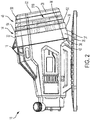
- a tool 10 may comprise and/or include a housing 11, a battery 12, shown schematically, and a battery cover 14 disposed over the battery 12.
- the battery 12 and/or the battery cover 14 may each be completely removable from the tool 10, or in some cases, the battery cover 14 may be attached to the tool 10, and may not be removable from the tool 10.
- the battery cover 14 may be pivotally coupled to the housing 11 via a pivot pin 18.
- the battery cover 14 may include multiple sides that form or define an inner cavity 36.
- the battery cover 14 includes a base 37 with at least a first side 22, a second side 26, a third side 30, and a fourth side 34.
- the first side 22 may be pivotally coupled to the tool 10.
- the first side 22 and the third side 30 may be generally parallel to each other, and the second side 26 and the fourth side 34 may be generally parallel to each other, although sides having other positions, arrangements, and/or geometries are contemplated.
- the sides may form a substantially quadratic shape that defines the inner cavity 36.
- the sides may form an alternative shape (e.g., a circular shape, an octagonal shape, or the like). In other embodiments, the sides may form an irregular or asymmetric shape. Outer surfaces 38 of the sides may be substantially flush with the outer surface 42 of the tool when the cover is in a closed position.
- the cover 14 may be moveable between the closed position and an open position.
- the closed position may form a seal against the tool 10 (e.g., via compression of a portion of the battery cover 14, compression of a sealing member (e.g., a gasket, O-ring, and/or the like) disposed in the battery cover 14, and/or the like), thus, preventing environmental elements, such as water or debris, from coming into contact with the battery 12 and the open position may provide access to the battery 12 (e.g., for facilitating removal and/or insertion of the battery 12).
- a sealing member e.g., a gasket, O-ring, and/or the like
- the battery cover 14 may be used with any other type of battery powered tool (e.g., a drill, a saw, an impact wrench, an impact driver, a multi-tool, a nailer, and/or the like).
- a drill e.g., a drill, a saw, an impact wrench, an impact driver, a multi-tool, a nailer, and/or the like.
- the battery cover 14 may include an expandable portion 46.
- the expandable portion 46 may include one or more panels 50.
- the panels 50 may be engaged with an adjacent panel via a stepped or angled portion 52.
- a first panel 54 of the panels 50 may be coupled to an inner surface of the battery cover sides (22, 26, 30, and 34).
- the expandable portion 46 may further include a last panel 58 that functions in a similar manner to the additional panels.
- the last panel 58 may additionally include a back panel 62.
- the back panel 62 may enclose the expandable portion 46 and the battery cover 14 such that, when the battery cover 14 is in the closed position, the battery 12 may not be accessible.
- the expandable portion 46 When a force is applied on the back panel 62 in a direction perpendicular to the back panel 62, the expandable portion 46 may move between a collapsed position and an expanded position. In the expanded position, the battery cover 14 may accommodate larger batteries than the battery cover 14 may accommodate in the collapsed position.
- Each panel 50 may include a first side, a second side, a third side, and a fourth side, such that a perimeter of an outer surface of the sides of the panel may be smaller than the perimeter of the inner surface of the preceding panel.
- the inner cavity 36 may be created by the sides of the battery cover 14 and the expandable portion 46. When the panels 50 are in the expanded position, an area of the inner cavity 36 may be greater than an area of the inner cavity 36 when the panels 50 are in the collapsed position. In other words, the inner cavity 36 may define a first internal area 51A in the collapsed position (shown in FIG. 1 ) and a second internal area 51B in the expanded position (shown in FIG. 2 ), the first internal area may be less than the second internal area.
- the panels 50 When the panels 50 are in the collapsed position, the panels 50 may be nested within the first panel 54 of the battery cover 14 such that the sides of the panels 50 may not be visible. In the expanded position, the sides of the panels 50 may be visible and, thus, the area of the inner cavity 36 of the battery cover 14 may be greater than when the panels 50 were collapsed.
- the panels 50 may include a height associated with each panel 50.
- the height may be measured as the distance between each panel 50 when the panels 50 are in the expanded position.
- the height may be constant between the first side, the second side, the third side, and the fourth side of the respective panel.
- the heights may correspond to the amount of additional area that may be provided when the expandable portion 46 is in the expanded position. In other words, an area of the panel 50 may be multiplied by the height of the panel 50 to determine the amount of additional area/volume that panel 50 provides in the expanded position.
- the height of each panel 50 may be substantially similar for all of the panels 50. In other embodiments, the height of each panel 50 may be different than the remainder of the panels 50.
- Each panel 50 may be collapsible relative to the proceeding panel via the angled portions 52.
- the angled portions 52 may be constructed from a flexible material (e.g., rubber, plastic, fabric, waterproof fabric, hydrogels, and/or the like) such that the angled portions 52 may be moveable from an outward angle position to an inward angle position.
- the outward angle position may be defined as a position in which the angled portions 52 are at angles greater than ninety degrees relative to the respective panels 50.
- the inward angle position may be defined as a position in which the angled portions 52 are at angles less than ninety degrees relative to the respective panels 50.
- the angled portions 52 may form an obtuse angle in the outward angle position and the angled portions 52 may form an acute angle in the inward angle position.
- the panels 50 may be nested within the first panel 54 in the collapsed position ( FIG. 1 ).
- the panels 50 may be in the expanded position ( FIG. 2 ).
- the outward angle position and the inward angle position may be predetermined such that the angled portion 52 may rest in either the outward angle position or the inward angle position.
- the position the angled portion 52 rests in may be dependent on which position the angled portion 52 is in a closer proximity to.
- a force generally normal to that of the back panel 62 may be imparted on an inner surface of the back panel 62.
- each angled portion 52 may begin to move from the inward angle position.
- the angled portion 52 may reach the outward angle position.
- the panels 50 may be in the expanded position.
- a reciprocating force may be imparted on an outer surface of the back panel 62. This force may move the angled portion 52 from the outward angle position to the inward angle position, thus moving the panels 50 to the collapsed position.
- the panels 50 may be formed, comprised, and/or composed of a silicone material, while the base 37 may be composed of a plastic material.
- the silicone material may be flexible to allow the panels 50 to move from the collapsed position to the expanded position to ensure adequate coverage of the battery 12.
- the angled portions 52 may also be composed of the silicone material.
- the angled portion 52 may be composed of a non-silicone material that is a different material than the panels 50.
- the plastic material of the base 37 may be sufficiently stiff, such that the battery sides may not significantly bend or deform.
- the expandable portion 46 may comprise a rigid cover that forms or defines an expanded space on or over a battery.
- a cover may comprise or be formed of a plastic material that can protect the battery from contaminants, moisture, and/or the like.
- a seal or sealing member may be disposed between the expandable portion 46 and the tool so that a liquid tight seal forms around the battery.
- FIGS. 4 and 5 disclose a battery cover 100 according to another embodiment of the present invention.
- the battery cover 100 may be similar to the battery cover 14. As such, only differences between the battery cover 100 and the battery cover 14 will be explained in detail.
- the battery cover 100 may include the panels 50, the angled portions 52, and the back panel 62, similar to the battery cover 14.
- the geometry of the battery cover 100 may be substantially similar to the battery cover 14.
- the battery cover 100 differs in that the battery cover 100 may be formed of a stretchable material different than the silicone material.
- the panels 50, the angled portions 52, and the back panel 62 may be composed of a composite rubber material, a waterproof fabric, and/or the like.
- the battery cover 100 may include a latch 104 that may be coupled to the base 37.
- the latch 104 may be moveable between a locked position and an unlocked position. In the locked position, the latch 104 may prevent the battery cover 100 from pivoting about the pivot pin 18. In the unlocked position, the latch 104 may allow the battery cover to pivot about the pivot pin 18. In some embodiments, the pivot pin 18 may not be included and, instead, an additional latch may be provided. In this embodiment, the latches may be positioned on opposite sides of the base 37 such that unlocking both latches allows the battery cover 100 to be removed. In other embodiments, latches may be positioned on every side of the base 37.
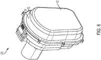
- FIG. 6 discloses a battery cover 200 according to another embodiment of the present invention.
- the battery cover 200 may be similar to the battery cover 100. As such, only differences between the battery cover 200 and the battery cover 100 will be explained in detail.
- the battery cover 200 may include the panel 50, the angled portion 52, and the back panel 62, similar to the battery cover 100.
- the battery cover 200 differs in that the battery cover 200 includes a singular panel 50 and a singular angled portion 52. In other words, when the battery cover 200 moves to the collapsed position, the singular angled portion 52 changes position.
- an accordion panel may be formed from the panel 50, the angled portions 52, and the back panel 62.
- the accordion panel When the accordion panel is in the expanded position, the accordion panel may be of a cuboid shape.
- the accordion panel When a force is applied on or over an outer surface of the accordion panel, the accordion panel may fold.
- the accordion panel When the accordion panel is folded, the accordion panel may be in the collapsed position. A force may be imparted on an inner surface of the accordion panel to move the accordion panel from the collapsed position to the expanded position.
- a continuous, flexible (e.g., rubber, etc.) panel may be formed from the panel 50, the angled portions 52, and the back panel 62.
- the continuous panel may be moveable between the expanded position and the collapsed position, whereby the continuous panel may be moved from the expanded position to the collapsed position via an application of force onto an outer surface of the continuous panel.
- the continuous panel When the continuous panel is compressed, the continuous panel may form the back surface of the expandable portion 46.
- a reciprocating force may be imparted on an inner surface of the continuous panel, which may move the continuous panel to the expanded position.
- each panel 50 may be slidable relative to the preceding panel via tracks (not shown).
- the tracks may allow the following panel to slide into and out of the preceding panel such that the expandable portion 46 may move from the collapsed position to the expanded position.
- the battery cover sides 22, 26, 30, and 34
- the panels 50 may include other mechanisms for producing a sliding relationship between the panels 50.
- a first locking feature may prevent motion of the panels 50 when the expandable portion 46 is in the collapsed position and a second locking feature (not shown) may prevent motion of the panels 50 when the expandable portion 46 is in the expanded position.
- Example locking features may include a detent, a clip, a hook, and/or the like. In yet another embodiment, additional locking features may be used so the cover is held in a partially expanded position.
- a force perpendicular to that of the back panel 62 may be imparted on an inner surface of the back panel 62.
- the first locking feature may be disengaged and the expandable portion 46 expands.
- the expandable portion 46 may reach the expanded position and the second locking feature may be engaged.
- a reciprocating force may be imparted on an outer surface of the back panel 62 to disengage the second locking feature and return the expandable portion 46 to the collapsed position.
- the expandable portion 46 may be moved to the collapsed position.
- the battery cover 14 may be expanded, and the expandable portion 46 may be moved to the expanded position. In this position, the battery cover 14 may allow the battery to fit within the battery cover 14.
Landscapes
- Chemical & Material Sciences (AREA)
- Chemical Kinetics & Catalysis (AREA)
- Electrochemistry (AREA)
- General Chemical & Material Sciences (AREA)
- Engineering & Computer Science (AREA)
- Mechanical Engineering (AREA)
- Inorganic Chemistry (AREA)
- Life Sciences & Earth Sciences (AREA)
- Biophysics (AREA)
- Computer Hardware Design (AREA)
- Battery Mounting, Suspending (AREA)
Applications Claiming Priority (1)
| Application Number | Priority Date | Filing Date | Title |
|---|---|---|---|
| US201862736785P | 2018-09-26 | 2018-09-26 |
Publications (3)
| Publication Number | Publication Date |
|---|---|
| EP3685966A2 true EP3685966A2 (fr) | 2020-07-29 |
| EP3685966A3 EP3685966A3 (fr) | 2020-09-02 |
| EP3685966B1 EP3685966B1 (fr) | 2022-10-12 |
Family
ID=68072159
Family Applications (1)
| Application Number | Title | Priority Date | Filing Date |
|---|---|---|---|
| EP19199902.8A Active EP3685966B1 (fr) | 2018-09-26 | 2019-09-26 | Couvercle de batterie et outil électrique doté d'un couvercle de batterie |
Country Status (4)
| Country | Link |
|---|---|
| US (1) | US11196119B2 (fr) |
| EP (1) | EP3685966B1 (fr) |
| CN (1) | CN211578799U (fr) |
| CA (1) | CA3056672A1 (fr) |
Families Citing this family (1)
| Publication number | Priority date | Publication date | Assignee | Title |
|---|---|---|---|---|
| KR102002641B1 (ko) * | 2019-04-23 | 2019-07-22 | 성원 | 배터리 교체형 유압장비의 방수하우징 |
Family Cites Families (23)
| Publication number | Priority date | Publication date | Assignee | Title |
|---|---|---|---|---|
| US4224385A (en) | 1979-01-02 | 1980-09-23 | P. R. Mallory & Co. Inc. | Expandable battery case |
| US20050257944A1 (en) * | 2004-05-20 | 2005-11-24 | Cooper Vincent P | Handle assembly for tool |
| US7038131B1 (en) | 2005-05-04 | 2006-05-02 | Arlington Industries, Inc. | Telescoping box adapter |
| US7396996B1 (en) | 2005-06-06 | 2008-07-08 | Taymac Corporation | Expandable in-use outlet cover |
| US8017865B1 (en) | 2005-06-06 | 2011-09-13 | Taymac Corporation | Collapsible while-in-use electrical outlet cover assembly |
| DE602005023917D1 (de) | 2005-10-07 | 2010-11-11 | Research In Motion Ltd | Tragbare elektronische Vorrichtung mit vielseitigem Batteriefach |
| US7687197B2 (en) | 2005-10-07 | 2010-03-30 | Research In Motion Limited | Expandable battery compartment for handheld electronic devices |
| US8101861B1 (en) | 2005-11-08 | 2012-01-24 | Taymac Corporation | Electrical device cover |
| US8569621B1 (en) | 2005-11-08 | 2013-10-29 | Hubbell Incorporated | Electrical device cover |
| US7381894B1 (en) | 2005-11-08 | 2008-06-03 | Taymac Corporation | Electrical device cover |
| US7619163B1 (en) | 2005-11-08 | 2009-11-17 | Taymac Corporation | Electrical device cover |
| US8053671B1 (en) | 2005-11-08 | 2011-11-08 | Taymac Corporation | Collapsible in-use cover |
| US7598454B1 (en) | 2006-05-26 | 2009-10-06 | Taymac Corporation | While in-use electrical device cover |
| US7678500B2 (en) | 2007-11-29 | 2010-03-16 | Itt Manufacturing Enterprises, Inc. | Expandable battery compartment |
| JP2012048885A (ja) * | 2010-08-25 | 2012-03-08 | Makita Corp | バッテリ装置 |
| JP2012054007A (ja) | 2010-08-31 | 2012-03-15 | Makita Corp | 電動工具のバッテリ装置 |
| US9172115B2 (en) | 2012-06-12 | 2015-10-27 | Milwaukee Electric Tool Corporation | Battery pack with multiple water discharge pathways |
| CN103887456A (zh) | 2012-12-20 | 2014-06-25 | 苏州宝时得电动工具有限公司 | 折叠电池包及电动工具 |
| WO2014167567A1 (fr) | 2013-04-08 | 2014-10-16 | Noam Hadas | Boîtier pour dispositif électronique mobile |
| US20170331082A1 (en) | 2014-10-30 | 2017-11-16 | Hitachi Koki Co. Ltd. | Electric device |
| CN210137159U (zh) | 2016-07-28 | 2020-03-10 | 豪倍公司 | 使用中的插座盖 |
| DE202016105813U1 (de) | 2016-10-18 | 2017-01-20 | Tranmax Machinery Co., Ltd. | Batterie-Packung |
| CN206163579U (zh) | 2016-11-22 | 2017-05-10 | 东莞市力腾辉电源科技有限公司 | 一种可折叠电池盒 |
-
2019
- 2019-09-24 US US16/581,007 patent/US11196119B2/en active Active
- 2019-09-25 CA CA3056672A patent/CA3056672A1/fr active Pending
- 2019-09-26 CN CN201921625199.1U patent/CN211578799U/zh active Active
- 2019-09-26 EP EP19199902.8A patent/EP3685966B1/fr active Active
Also Published As
| Publication number | Publication date |
|---|---|
| CN211578799U (zh) | 2020-09-25 |
| US20200099021A1 (en) | 2020-03-26 |
| US11196119B2 (en) | 2021-12-07 |
| EP3685966A3 (fr) | 2020-09-02 |
| CA3056672A1 (fr) | 2020-03-26 |
| EP3685966B1 (fr) | 2022-10-12 |
Similar Documents
| Publication | Publication Date | Title |
|---|---|---|
| EP2522468B1 (fr) | Boîtier de stockage d'outil électrique | |
| ES2723884T3 (es) | Caja de herramientas | |
| AU2009244648B2 (en) | Tool storage cabinet | |
| US20070025647A1 (en) | Collapsible tool bag | |
| US20230013694A1 (en) | Storage system | |
| US20060027475A1 (en) | Tool storage and carrier assembly | |
| US20130186795A1 (en) | Tray Case | |
| RU2663819C2 (ru) | Термозащитный кожух батареи автотранспортного средства | |
| AU2005218030A1 (en) | Large tough case extension case cover latch | |
| US20160139635A1 (en) | Protective case for hybrid computer | |
| WO2006083227A1 (fr) | Coffret | |
| US11196119B2 (en) | Collapsible cover for a battery pack | |
| IL269564B2 (en) | Sawhorse | |
| TWI673746B (zh) | 殼體防水扣接結構及具有殼體防水扣接結構的門鈴裝置 | |
| JP2003143268A5 (fr) | ||
| JP5307519B2 (ja) | 集塵機 | |
| JP5332340B2 (ja) | 筐体構造 | |
| JP4213018B2 (ja) | 荷物係止装置 | |
| EP2241954B1 (fr) | Dispositif électronique portable doté d'un compartiment de batterie polyvalent | |
| US20040198243A1 (en) | Mobile phone with a replaceable face panel | |
| JP4449438B2 (ja) | 化粧品用コンパクト容器 | |
| US20060278635A1 (en) | Tool box having latching device | |
| CN209825463U (zh) | 一种基于物理实验用的实验工具箱 | |
| JP5853322B2 (ja) | ワゴン | |
| CN201022247Y (zh) | 面板结构 |
Legal Events
| Date | Code | Title | Description |
|---|---|---|---|
| PUAI | Public reference made under article 153(3) epc to a published international application that has entered the european phase |
Free format text: ORIGINAL CODE: 0009012 |
|
| STAA | Information on the status of an ep patent application or granted ep patent |
Free format text: STATUS: THE APPLICATION HAS BEEN PUBLISHED |
|
| AK | Designated contracting states |
Kind code of ref document: A2 Designated state(s): AL AT BE BG CH CY CZ DE DK EE ES FI FR GB GR HR HU IE IS IT LI LT LU LV MC MK MT NL NO PL PT RO RS SE SI SK SM TR |
|
| AX | Request for extension of the european patent |
Extension state: BA ME |
|
| PUAL | Search report despatched |
Free format text: ORIGINAL CODE: 0009013 |
|
| AK | Designated contracting states |
Kind code of ref document: A3 Designated state(s): AL AT BE BG CH CY CZ DE DK EE ES FI FR GB GR HR HU IE IS IT LI LT LU LV MC MK MT NL NO PL PT RO RS SE SI SK SM TR |
|
| AX | Request for extension of the european patent |
Extension state: BA ME |
|
| RIC1 | Information provided on ipc code assigned before grant |
Ipc: B25F 5/02 20060101AFI20200728BHEP |
|
| RAP1 | Party data changed (applicant data changed or rights of an application transferred) |
Owner name: TTI (MACAO COMMERCIAL OFFSHORE) LIMITED |
|
| STAA | Information on the status of an ep patent application or granted ep patent |
Free format text: STATUS: REQUEST FOR EXAMINATION WAS MADE |
|
| 17P | Request for examination filed |
Effective date: 20201204 |
|
| RBV | Designated contracting states (corrected) |
Designated state(s): AL AT BE BG CH CY CZ DE DK EE ES FI FR GB GR HR HU IE IS IT LI LT LU LV MC MK MT NL NO PL PT RO RS SE SI SK SM TR |
|
| RAP1 | Party data changed (applicant data changed or rights of an application transferred) |
Owner name: TECHTRONIC CORDLESS GP |
|
| GRAP | Despatch of communication of intention to grant a patent |
Free format text: ORIGINAL CODE: EPIDOSNIGR1 |
|
| STAA | Information on the status of an ep patent application or granted ep patent |
Free format text: STATUS: GRANT OF PATENT IS INTENDED |
|
| INTG | Intention to grant announced |
Effective date: 20220722 |
|
| GRAS | Grant fee paid |
Free format text: ORIGINAL CODE: EPIDOSNIGR3 |
|
| GRAA | (expected) grant |
Free format text: ORIGINAL CODE: 0009210 |
|
| STAA | Information on the status of an ep patent application or granted ep patent |
Free format text: STATUS: THE PATENT HAS BEEN GRANTED |
|
| AK | Designated contracting states |
Kind code of ref document: B1 Designated state(s): AL AT BE BG CH CY CZ DE DK EE ES FI FR GB GR HR HU IE IS IT LI LT LU LV MC MK MT NL NO PL PT RO RS SE SI SK SM TR |
|
| REG | Reference to a national code |
Ref country code: GB Ref legal event code: FG4D |
|
| RIN1 | Information on inventor provided before grant (corrected) |
Inventor name: WILLIAMS, BRIANNA E. Inventor name: ELLIOTT, HALLE |
|
| REG | Reference to a national code |
Ref country code: CH Ref legal event code: EP |
|
| REG | Reference to a national code |
Ref country code: DE Ref legal event code: R096 Ref document number: 602019020482 Country of ref document: DE |
|
| REG | Reference to a national code |
Ref country code: IE Ref legal event code: FG4D |
|
| REG | Reference to a national code |
Ref country code: AT Ref legal event code: REF Ref document number: 1523876 Country of ref document: AT Kind code of ref document: T Effective date: 20221115 |
|
| REG | Reference to a national code |
Ref country code: LT Ref legal event code: MG9D |
|
| REG | Reference to a national code |
Ref country code: NL Ref legal event code: MP Effective date: 20221012 |
|
| REG | Reference to a national code |
Ref country code: AT Ref legal event code: MK05 Ref document number: 1523876 Country of ref document: AT Kind code of ref document: T Effective date: 20221012 |
|
| PG25 | Lapsed in a contracting state [announced via postgrant information from national office to epo] |
Ref country code: NL Free format text: LAPSE BECAUSE OF FAILURE TO SUBMIT A TRANSLATION OF THE DESCRIPTION OR TO PAY THE FEE WITHIN THE PRESCRIBED TIME-LIMIT Effective date: 20221012 |
|
| PG25 | Lapsed in a contracting state [announced via postgrant information from national office to epo] |
Ref country code: SE Free format text: LAPSE BECAUSE OF FAILURE TO SUBMIT A TRANSLATION OF THE DESCRIPTION OR TO PAY THE FEE WITHIN THE PRESCRIBED TIME-LIMIT Effective date: 20221012 Ref country code: PT Free format text: LAPSE BECAUSE OF FAILURE TO SUBMIT A TRANSLATION OF THE DESCRIPTION OR TO PAY THE FEE WITHIN THE PRESCRIBED TIME-LIMIT Effective date: 20230213 Ref country code: NO Free format text: LAPSE BECAUSE OF FAILURE TO SUBMIT A TRANSLATION OF THE DESCRIPTION OR TO PAY THE FEE WITHIN THE PRESCRIBED TIME-LIMIT Effective date: 20230112 Ref country code: LT Free format text: LAPSE BECAUSE OF FAILURE TO SUBMIT A TRANSLATION OF THE DESCRIPTION OR TO PAY THE FEE WITHIN THE PRESCRIBED TIME-LIMIT Effective date: 20221012 Ref country code: FI Free format text: LAPSE BECAUSE OF FAILURE TO SUBMIT A TRANSLATION OF THE DESCRIPTION OR TO PAY THE FEE WITHIN THE PRESCRIBED TIME-LIMIT Effective date: 20221012 Ref country code: ES Free format text: LAPSE BECAUSE OF FAILURE TO SUBMIT A TRANSLATION OF THE DESCRIPTION OR TO PAY THE FEE WITHIN THE PRESCRIBED TIME-LIMIT Effective date: 20221012 Ref country code: AT Free format text: LAPSE BECAUSE OF FAILURE TO SUBMIT A TRANSLATION OF THE DESCRIPTION OR TO PAY THE FEE WITHIN THE PRESCRIBED TIME-LIMIT Effective date: 20221012 |
|
| PG25 | Lapsed in a contracting state [announced via postgrant information from national office to epo] |
Ref country code: RS Free format text: LAPSE BECAUSE OF FAILURE TO SUBMIT A TRANSLATION OF THE DESCRIPTION OR TO PAY THE FEE WITHIN THE PRESCRIBED TIME-LIMIT Effective date: 20221012 Ref country code: PL Free format text: LAPSE BECAUSE OF FAILURE TO SUBMIT A TRANSLATION OF THE DESCRIPTION OR TO PAY THE FEE WITHIN THE PRESCRIBED TIME-LIMIT Effective date: 20221012 Ref country code: LV Free format text: LAPSE BECAUSE OF FAILURE TO SUBMIT A TRANSLATION OF THE DESCRIPTION OR TO PAY THE FEE WITHIN THE PRESCRIBED TIME-LIMIT Effective date: 20221012 Ref country code: IS Free format text: LAPSE BECAUSE OF FAILURE TO SUBMIT A TRANSLATION OF THE DESCRIPTION OR TO PAY THE FEE WITHIN THE PRESCRIBED TIME-LIMIT Effective date: 20230212 Ref country code: HR Free format text: LAPSE BECAUSE OF FAILURE TO SUBMIT A TRANSLATION OF THE DESCRIPTION OR TO PAY THE FEE WITHIN THE PRESCRIBED TIME-LIMIT Effective date: 20221012 Ref country code: GR Free format text: LAPSE BECAUSE OF FAILURE TO SUBMIT A TRANSLATION OF THE DESCRIPTION OR TO PAY THE FEE WITHIN THE PRESCRIBED TIME-LIMIT Effective date: 20230113 |
|
| REG | Reference to a national code |
Ref country code: DE Ref legal event code: R097 Ref document number: 602019020482 Country of ref document: DE |
|
| PG25 | Lapsed in a contracting state [announced via postgrant information from national office to epo] |
Ref country code: SM Free format text: LAPSE BECAUSE OF FAILURE TO SUBMIT A TRANSLATION OF THE DESCRIPTION OR TO PAY THE FEE WITHIN THE PRESCRIBED TIME-LIMIT Effective date: 20221012 Ref country code: RO Free format text: LAPSE BECAUSE OF FAILURE TO SUBMIT A TRANSLATION OF THE DESCRIPTION OR TO PAY THE FEE WITHIN THE PRESCRIBED TIME-LIMIT Effective date: 20221012 Ref country code: EE Free format text: LAPSE BECAUSE OF FAILURE TO SUBMIT A TRANSLATION OF THE DESCRIPTION OR TO PAY THE FEE WITHIN THE PRESCRIBED TIME-LIMIT Effective date: 20221012 Ref country code: DK Free format text: LAPSE BECAUSE OF FAILURE TO SUBMIT A TRANSLATION OF THE DESCRIPTION OR TO PAY THE FEE WITHIN THE PRESCRIBED TIME-LIMIT Effective date: 20221012 Ref country code: CZ Free format text: LAPSE BECAUSE OF FAILURE TO SUBMIT A TRANSLATION OF THE DESCRIPTION OR TO PAY THE FEE WITHIN THE PRESCRIBED TIME-LIMIT Effective date: 20221012 |
|
| PLBE | No opposition filed within time limit |
Free format text: ORIGINAL CODE: 0009261 |
|
| STAA | Information on the status of an ep patent application or granted ep patent |
Free format text: STATUS: NO OPPOSITION FILED WITHIN TIME LIMIT |
|
| PG25 | Lapsed in a contracting state [announced via postgrant information from national office to epo] |
Ref country code: SK Free format text: LAPSE BECAUSE OF FAILURE TO SUBMIT A TRANSLATION OF THE DESCRIPTION OR TO PAY THE FEE WITHIN THE PRESCRIBED TIME-LIMIT Effective date: 20221012 Ref country code: AL Free format text: LAPSE BECAUSE OF FAILURE TO SUBMIT A TRANSLATION OF THE DESCRIPTION OR TO PAY THE FEE WITHIN THE PRESCRIBED TIME-LIMIT Effective date: 20221012 |
|
| 26N | No opposition filed |
Effective date: 20230713 |
|
| PG25 | Lapsed in a contracting state [announced via postgrant information from national office to epo] |
Ref country code: SI Free format text: LAPSE BECAUSE OF FAILURE TO SUBMIT A TRANSLATION OF THE DESCRIPTION OR TO PAY THE FEE WITHIN THE PRESCRIBED TIME-LIMIT Effective date: 20221012 |
|
| REG | Reference to a national code |
Ref country code: CH Ref legal event code: PL |
|
| PG25 | Lapsed in a contracting state [announced via postgrant information from national office to epo] |
Ref country code: LU Free format text: LAPSE BECAUSE OF NON-PAYMENT OF DUE FEES Effective date: 20230926 |
|
| REG | Reference to a national code |
Ref country code: BE Ref legal event code: MM Effective date: 20230930 |
|
| PG25 | Lapsed in a contracting state [announced via postgrant information from national office to epo] |
Ref country code: LU Free format text: LAPSE BECAUSE OF NON-PAYMENT OF DUE FEES Effective date: 20230926 Ref country code: IT Free format text: LAPSE BECAUSE OF FAILURE TO SUBMIT A TRANSLATION OF THE DESCRIPTION OR TO PAY THE FEE WITHIN THE PRESCRIBED TIME-LIMIT Effective date: 20221012 Ref country code: MC Free format text: LAPSE BECAUSE OF FAILURE TO SUBMIT A TRANSLATION OF THE DESCRIPTION OR TO PAY THE FEE WITHIN THE PRESCRIBED TIME-LIMIT Effective date: 20221012 |
|
| REG | Reference to a national code |
Ref country code: IE Ref legal event code: MM4A |
|
| PG25 | Lapsed in a contracting state [announced via postgrant information from national office to epo] |
Ref country code: IE Free format text: LAPSE BECAUSE OF NON-PAYMENT OF DUE FEES Effective date: 20230926 |
|
| PG25 | Lapsed in a contracting state [announced via postgrant information from national office to epo] |
Ref country code: CH Free format text: LAPSE BECAUSE OF NON-PAYMENT OF DUE FEES Effective date: 20230930 |
|
| PG25 | Lapsed in a contracting state [announced via postgrant information from national office to epo] |
Ref country code: IE Free format text: LAPSE BECAUSE OF NON-PAYMENT OF DUE FEES Effective date: 20230926 Ref country code: CH Free format text: LAPSE BECAUSE OF NON-PAYMENT OF DUE FEES Effective date: 20230930 |
|
| PG25 | Lapsed in a contracting state [announced via postgrant information from national office to epo] |
Ref country code: BE Free format text: LAPSE BECAUSE OF NON-PAYMENT OF DUE FEES Effective date: 20230930 |
|
| PG25 | Lapsed in a contracting state [announced via postgrant information from national office to epo] |
Ref country code: BG Free format text: LAPSE BECAUSE OF FAILURE TO SUBMIT A TRANSLATION OF THE DESCRIPTION OR TO PAY THE FEE WITHIN THE PRESCRIBED TIME-LIMIT Effective date: 20221012 |
|
| PG25 | Lapsed in a contracting state [announced via postgrant information from national office to epo] |
Ref country code: BG Free format text: LAPSE BECAUSE OF FAILURE TO SUBMIT A TRANSLATION OF THE DESCRIPTION OR TO PAY THE FEE WITHIN THE PRESCRIBED TIME-LIMIT Effective date: 20221012 |
|
| PG25 | Lapsed in a contracting state [announced via postgrant information from national office to epo] |
Ref country code: CY Free format text: LAPSE BECAUSE OF FAILURE TO SUBMIT A TRANSLATION OF THE DESCRIPTION OR TO PAY THE FEE WITHIN THE PRESCRIBED TIME-LIMIT; INVALID AB INITIO Effective date: 20190926 |
|
| PG25 | Lapsed in a contracting state [announced via postgrant information from national office to epo] |
Ref country code: HU Free format text: LAPSE BECAUSE OF FAILURE TO SUBMIT A TRANSLATION OF THE DESCRIPTION OR TO PAY THE FEE WITHIN THE PRESCRIBED TIME-LIMIT; INVALID AB INITIO Effective date: 20190926 |
|
| PGFP | Annual fee paid to national office [announced via postgrant information from national office to epo] |
Ref country code: DE Payment date: 20250929 Year of fee payment: 7 |
|
| PGFP | Annual fee paid to national office [announced via postgrant information from national office to epo] |
Ref country code: GB Payment date: 20250929 Year of fee payment: 7 |
|
| PGFP | Annual fee paid to national office [announced via postgrant information from national office to epo] |
Ref country code: FR Payment date: 20250925 Year of fee payment: 7 |
|
| PG25 | Lapsed in a contracting state [announced via postgrant information from national office to epo] |
Ref country code: TR Free format text: LAPSE BECAUSE OF FAILURE TO SUBMIT A TRANSLATION OF THE DESCRIPTION OR TO PAY THE FEE WITHIN THE PRESCRIBED TIME-LIMIT Effective date: 20221012 |