EP3685987B1 - Verfahren zum kopieren einer oberflächentextur eines oberflächenträgerobjekts auf eine luftdichte thermoplastische oberflächenschicht einer innenverkleidungskomponente eines fahrzeugs - Google Patents
Verfahren zum kopieren einer oberflächentextur eines oberflächenträgerobjekts auf eine luftdichte thermoplastische oberflächenschicht einer innenverkleidungskomponente eines fahrzeugs Download PDFInfo
- Publication number
- EP3685987B1 EP3685987B1 EP19153542.6A EP19153542A EP3685987B1 EP 3685987 B1 EP3685987 B1 EP 3685987B1 EP 19153542 A EP19153542 A EP 19153542A EP 3685987 B1 EP3685987 B1 EP 3685987B1
- Authority
- EP
- European Patent Office
- Prior art keywords
- pressure chamber
- surface layer
- carrier object
- pressure
- airtight thermoplastic
- Prior art date
- Legal status (The legal status is an assumption and is not a legal conclusion. Google has not performed a legal analysis and makes no representation as to the accuracy of the status listed.)
- Active
Links
Images

Classifications
-
- B—PERFORMING OPERATIONS; TRANSPORTING
- B29—WORKING OF PLASTICS; WORKING OF SUBSTANCES IN A PLASTIC STATE IN GENERAL
- B29C—SHAPING OR JOINING OF PLASTICS; SHAPING OF MATERIAL IN A PLASTIC STATE, NOT OTHERWISE PROVIDED FOR; AFTER-TREATMENT OF THE SHAPED PRODUCTS, e.g. REPAIRING
- B29C59/00—Surface shaping of articles, e.g. embossing; Apparatus therefor
- B29C59/02—Surface shaping of articles, e.g. embossing; Apparatus therefor by mechanical means, e.g. pressing
-
- B—PERFORMING OPERATIONS; TRANSPORTING
- B29—WORKING OF PLASTICS; WORKING OF SUBSTANCES IN A PLASTIC STATE IN GENERAL
- B29C—SHAPING OR JOINING OF PLASTICS; SHAPING OF MATERIAL IN A PLASTIC STATE, NOT OTHERWISE PROVIDED FOR; AFTER-TREATMENT OF THE SHAPED PRODUCTS, e.g. REPAIRING
- B29C59/00—Surface shaping of articles, e.g. embossing; Apparatus therefor
- B29C59/02—Surface shaping of articles, e.g. embossing; Apparatus therefor by mechanical means, e.g. pressing
- B29C59/022—Surface shaping of articles, e.g. embossing; Apparatus therefor by mechanical means, e.g. pressing characterised by the disposition or the configuration, e.g. dimensions, of the embossments or the shaping tools therefor
-
- B—PERFORMING OPERATIONS; TRANSPORTING
- B29—WORKING OF PLASTICS; WORKING OF SUBSTANCES IN A PLASTIC STATE IN GENERAL
- B29C—SHAPING OR JOINING OF PLASTICS; SHAPING OF MATERIAL IN A PLASTIC STATE, NOT OTHERWISE PROVIDED FOR; AFTER-TREATMENT OF THE SHAPED PRODUCTS, e.g. REPAIRING
- B29C59/00—Surface shaping of articles, e.g. embossing; Apparatus therefor
- B29C59/002—Component parts, details or accessories; Auxiliary operations
-
- B—PERFORMING OPERATIONS; TRANSPORTING
- B33—ADDITIVE MANUFACTURING TECHNOLOGY
- B33Y—ADDITIVE MANUFACTURING, i.e. MANUFACTURING OF THREE-DIMENSIONAL [3D] OBJECTS BY ADDITIVE DEPOSITION, ADDITIVE AGGLOMERATION OR ADDITIVE LAYERING, e.g. BY 3D PRINTING, STEREOLITHOGRAPHY OR SELECTIVE LASER SINTERING
- B33Y80/00—Products made by additive manufacturing
-
- B—PERFORMING OPERATIONS; TRANSPORTING
- B29—WORKING OF PLASTICS; WORKING OF SUBSTANCES IN A PLASTIC STATE IN GENERAL
- B29C—SHAPING OR JOINING OF PLASTICS; SHAPING OF MATERIAL IN A PLASTIC STATE, NOT OTHERWISE PROVIDED FOR; AFTER-TREATMENT OF THE SHAPED PRODUCTS, e.g. REPAIRING
- B29C35/00—Heating, cooling or curing, e.g. crosslinking or vulcanising; Apparatus therefor
- B29C35/02—Heating or curing, e.g. crosslinking or vulcanizing during moulding, e.g. in a mould
- B29C35/04—Heating or curing, e.g. crosslinking or vulcanizing during moulding, e.g. in a mould using liquids, gas or steam
- B29C35/045—Heating or curing, e.g. crosslinking or vulcanizing during moulding, e.g. in a mould using liquids, gas or steam using gas or flames
- B29C2035/046—Heating or curing, e.g. crosslinking or vulcanizing during moulding, e.g. in a mould using liquids, gas or steam using gas or flames dried air
-
- B—PERFORMING OPERATIONS; TRANSPORTING
- B29—WORKING OF PLASTICS; WORKING OF SUBSTANCES IN A PLASTIC STATE IN GENERAL
- B29C—SHAPING OR JOINING OF PLASTICS; SHAPING OF MATERIAL IN A PLASTIC STATE, NOT OTHERWISE PROVIDED FOR; AFTER-TREATMENT OF THE SHAPED PRODUCTS, e.g. REPAIRING
- B29C35/00—Heating, cooling or curing, e.g. crosslinking or vulcanising; Apparatus therefor
- B29C35/02—Heating or curing, e.g. crosslinking or vulcanizing during moulding, e.g. in a mould
- B29C35/08—Heating or curing, e.g. crosslinking or vulcanizing during moulding, e.g. in a mould by wave energy or particle radiation
- B29C35/0805—Heating or curing, e.g. crosslinking or vulcanizing during moulding, e.g. in a mould by wave energy or particle radiation using electromagnetic radiation
- B29C2035/0822—Heating or curing, e.g. crosslinking or vulcanizing during moulding, e.g. in a mould by wave energy or particle radiation using electromagnetic radiation using IR radiation
-
- B—PERFORMING OPERATIONS; TRANSPORTING
- B29—WORKING OF PLASTICS; WORKING OF SUBSTANCES IN A PLASTIC STATE IN GENERAL
- B29L—INDEXING SCHEME ASSOCIATED WITH SUBCLASS B29C, RELATING TO PARTICULAR ARTICLES
- B29L2031/00—Other particular articles
- B29L2031/58—Upholstery or cushions, e.g. vehicle upholstery or interior padding
-
- B—PERFORMING OPERATIONS; TRANSPORTING
- B33—ADDITIVE MANUFACTURING TECHNOLOGY
- B33Y—ADDITIVE MANUFACTURING, i.e. MANUFACTURING OF THREE-DIMENSIONAL [3D] OBJECTS BY ADDITIVE DEPOSITION, ADDITIVE AGGLOMERATION OR ADDITIVE LAYERING, e.g. BY 3D PRINTING, STEREOLITHOGRAPHY OR SELECTIVE LASER SINTERING
- B33Y10/00—Processes of additive manufacturing
-
- B—PERFORMING OPERATIONS; TRANSPORTING
- B60—VEHICLES IN GENERAL
- B60R—VEHICLES, VEHICLE FITTINGS, OR VEHICLE PARTS, NOT OTHERWISE PROVIDED FOR
- B60R13/00—Elements for body-finishing, identifying, or decorating; Arrangements or adaptations for advertising purposes
- B60R13/02—Internal Trim mouldings ; Internal Ledges; Wall liners for passenger compartments; Roof liners
Definitions
- the present invention relates to a method for copying a surface texture of a surface carrier object to an airtight thermoplastic surface layer of an interior cladding component of a vehicle. Moreover the present disclosure relates to an interior cladding component of a vehicle, comprising an airtight thermoplastic surface layer obtained by such a method.
- the vehicle design is becoming a more and more important factor for the purchase decision of the vehicle customers. This is not only true for the exterior vehicle design but also for the interior vehicle design. Particularly the interior design can be tailored according to the individual customer requests. Common examples of the interior design the customer can determine is the color and the material of the seat cover. Usually the interior cladding comprises a number of decoration elements. The decoration elements may have a metal-like or wood-like appearance. Next to the seat cover the vehicle customer may decide on the color of the surface of the interior cladding.
- the surface texture of the cladding components can be selected by the vehicle customer.
- an embodiment of the present disclosure has the object to provide an interior cladding component of a vehicle the surface texture of which can be chosen out of a broad variety at reasonable costs.
- One embodiment of the present disclosure is directed to a method for copying a surface texture of a surface carrier object to an airtight thermoplastic surface layer of an interior cladding component of a vehicle by means of a manufacturing device, the manufacturing device comprising
- the present disclosure provides a method for copying a surface texture of a surface carrier object to an airtight thermoplastic surface layer. Similar methods are disclosed in DE 10 2016 112 505 A1 , WO 2014/013563 A1 , US 2011/287124 A1 , US 2003/072917 A1 , US 4 092 200 A , US 3 244 571 A and EP 0 299 168 A2 . Document WO 2014/013563 A1 discloses a method for copying a surface texture of a surface carrier object according to the preamble of claim 1. However, the surface layers used in the methods disclosed in these documents are not airtight so the methods comprise different steps.
- the surface layer obtained by the present method can be applied to an interior cladding component of a vehicle.
- the surface texture of the surface carrier object can be copied in principle as often as desired in a fairly simple and fast way.
- the costs and the time for providing a given interior cladding component with the selected surface texture are kept low. Due to the fact that the surface layer is airtight the forces needed to copy the surface texture to the surface layer are almost exclusively provided by pressure differences between the first pressure chamber section and the second pressure chamber section. Mechanical units that contact the surface layer for applying forces are not needed.
- the design of the manufacturing device is thus simple.
- the surface layer can be treated in a gentle way avoiding damages.
- the number of defective surface layers is kept low. In case another surface texture is desired the surface carrier object is exchanged which is not a time consuming step.
- the variety of surface textures the vehicle customer can choose from can be increased without a significant effort.
- the method according to a further embodiment may comprise the step of heating the airtight thermoplastic surface layer up to or near to the softening point of the airtight thermoplastic surface layer by a heating unit.
- the heating unit may comprise infrared or halogen lamps.
- the heating unit may also apply hot air to the surface layer. Due to the fact that the surface layer is made of a thermoplastic it is softened with increasing heat. Therefore the copying of the surface texture from the surface carrier object to the surface layer is facilitated as the force needed is reduced.
- the surface texture of the surface carrier object is made by a digital printer or a 3D-printer.
- the surface carrier object can be provided in a simple and fast way.
- the vehicle customer may even create her or his own surface texture on a computer and transfer it to the digital printer or 3D-printer.
- a very high degree of individualization may be offered at still acceptable costs and efforts.
- the positioning device comprises a moving unit for moving the surface carrier object inside the pressure chamber, the method comprising the step of
- the positioning device can move the surface carrier object.
- the possibility to move the surface carrier object within the pressure chamber facilitates the fastening of the surface layer inside the pressure chamber.
- the fastening of the surface layer inside the pressure chamber can be conducted when the surface carrier object is in the first position and thus at distance from the positioning device.
- the surface carrier object does not obstruct the fastening of the surface layer inside the pressure chamber.
- a negative pressure is applied in both pressure chamber sections.
- the negative pressure is produced on both pressure chamber sections, i.e. on both sides of the surface layer.
- the pressure induced forces acting on the surface layer are cancelling each other.
- the negative pressure in the pressure chamber section in which the surface carrier object is located is maintained while in the other pressure chamber section the negative pressure is released.
- the resulting force is provided within a short time and is pressing the surface layer against the surface carrier object, thereby copying the surface texture from the surface carrier object to the surface layer.
- the crucial step is conducted and no force is needed anymore to press the surface layer against the surface carrier object.
- the negative pressure in the pressure chamber section comprising the surface carrier object can be released. No more pressure induced forces are acting on the surface layer anymore.
- a further embodiment is characterized in that the method according to one of the preceding embodiments is repeated with the airtight thermoplastic surface layer from the pressure chamber, comprising the step of
- both sides of the surface layer may be provided with the surface texture.
- the surface texture of the surface carrier object is made of silicone or polyurethane. These materials are particularly suited to provide the surface texture to be copied to the surface layer.
- the surface texture of the surface carrier object made of silicone or polyurethane may be generated by copying any given surface of a physical entity, be it stone, wood, textile or the like, or by copying a surface generated by digital printers or 3D-printers.
- the airtight thermoplastic surface layer is made of a thermoplastic polyolefin, thermoplastic polyurethane or polycarbonate. These materials are particularly suited to be used for surface layers of vehicle cladding components. Moreover, their melting point is fairly low so that the energy consumed during the manufacturing process is modest.
- Another implementation of the disclosure is directed to an interior cladding component of a vehicle, comprising an airtight thermoplastic surface layer obtained by a method according to one of the preceding embodiments.
- the technical effects and advantages as discussed with regard to the embodiments of the present method equally apply to the interior cladding.
- a given surface layer can be provided with a desired surface texture by a simple and fairly inexpensive process. Beyond that the variety of surface textures a vehicle customer can choose from may be increased without a significant increase of the manufacturing costs.
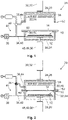
- FIGs 1 to 6 different steps of one embodiment of an inventive method for copying a surface texture 10 of a surface carrier object 12 to an airtight thermoplastic surface layer 14 of an interior cladding component 16 of a vehicle 18 (see Figure 8 ).
- the method is conducted in a manufacturing device 20 that comprises a pressure chamber 22 having a housing 24 that is encompassing the pressure chamber 22.
- the housing is subdivided into a first housing part 26 and a second housing part 28.
- At least one of the housing parts, in the embodiment shown the second housing part 28 is translationally movable relative to the first housing part 26 between an open position that is shown in Figures 1 and 6 and a closed position that is shown in Figures 2 to 5 .
- the second housing part 28 can be shifted between the open position and the closed position by an opening and closing device 30 that may comprise a piston-cylinder-unit 32.
- the pressure chamber 22 is accessible from outside while in the closed position the pressure chamber 22 is hermitically sealed.
- the manufacturing device 20 further comprises a first pressure adjusting unit 34 and a second pressure adjusting unit 36 for adjusting the pressure inside the pressure chamber 22.
- the manufacturing device 20 comprises a vacuum pump 38 that is in fluid communication with the pressure chamber 22 by a hose system 40 that comprises a first hose 42 and a second hose 44.
- the first hose 42 is connected to the pressure chamber 22 through the first housing part 26 whereas the second hose 44 is connected to the pressure chamber 22 through the second housing part 28.
- the first pressure adjusting unit 34 comprises the first hose 42 and the second pressure adjusting unit 36 comprises the second hose 44.
- the hose system 40 comprises a valve 46 by which the fluid communication between the first hose 42 and the second hose 44 can be established and interrupted.
- the first hose 42 and the second hose 44 may be exposed to the atmospheric pressure by the valve 46.
- the manufacturing device 20 is equipped with a positioning device 48 for positioning the surface carrier object 12 inside the pressure chamber 22.
- the positioning device 48 may comprise a moving unit 49 having a piston-cylinder-unit 50 for translationally moving the surface carrier object 12 within the pressure chamber 22.
- the surface carrier object 12 comprises the surface texture 10 that is to be copied to the surface layer 14.
- the surface layer 14 is fixed inside the pressure chamber 22 by means of a fixing device 52.
- the surface layer 14 is fixed such that it completely penetrates the pressure chamber 22.
- the second housing part 28 is moved into the closed position the surface layer 14 subdivides the pressure chamber 22 into a first pressure chamber section 54 and a second pressure chamber section 56 that are hermetically and airtightly divided from each other by the surface layer 14.
- the manufacturing device 20 is furnished with a heating unit 58 that comprises a number of infrared lights.
- the second housing part 28 is located in the open position.
- the pressure chamber 22 is accessible from the outside.
- the positioning device 48 is located in a first position near the bottom of the pressure chamber 22.
- the valve 46 is in a position in which the first hose 42 and the second hose 44 are exposed to atmospheric pressure.
- the surface layer 14 is placed into the fixing device 52 and the second housing part 28 moved into the closed position as shown in Figure 2 .
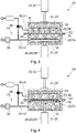
- the valve 46 is switched into a position in which the first hose 42 and the second hose 44 are both connected to the vacuum pump 38.
- the vacuum pump 38 is turned on thereby applying a negative pressure in the first pressure chamber section 54 and the second pressure chamber section 56.
- the negative pressure is symbolized by the crosshatching.
- the heating unit 58 is turned on, thereby heating up the surface layer 14.
- the heat generated by the heating unit 58 is symbolized by the sinuous lines H in Figure 3 .
- valve 46 is closed once the desired negative pressure is reached.
- the negative pressure is thus maintained inside the pressure chamber 22.
- the vacuum pump 38 may now be turned-off.
- the moving unit 48 of the positioning device 48 is now activated and moves the surface carrier object 12 into a second position.
- the first housing part 26 comprises protrusions 60 extending into the pressure chamber 22 on which the positioning device 48 abuts in the second positon.
- the surface carrier object 12 is touching the surface layer 14 so that it is slightly deformed towards the heating unit 58.
- valve 46 is now switched into a positon in which the second pressure chamber section 56 is exposed to atmospheric pressure while the first pressure chamber section 54 is still airtightly closed.
- the surface layer 14 is sucked towards the first pressure chamber section 54 and towards the surface carrier object 12.
- the surface layer 14 is thereby pressed on the surface carrier object 12 and the surface texture 10 of the surface carrier object 12 is copied to the side of the surface layer 14 facing the surface carrier object 12.
- valve 46 is switched into a position in which also the first pressure chamber section 54 is exposed to atmospheric pressure.
- the second housing part 28 is moved into the open position by activating the opening and closing device 30.
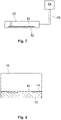
- the surface layer 14 now comprising the surface texture 10 copied from the surface carrier object 12 can now be removed from the manufacturing device 20 (see Figure 6 ). The process can now be repeated either using another surface layer 14 or turning over the removed surface layer 14 to copy the surface texture 10 to the untreated surface.
- a printer 62 either a digital printer or a 3D-printer, is shown that is generating the surface carrier object 12.
- the surface carrier object 12 or its surface texture 10 may be made of any suitable object such as stone, metal, wood textile or the like. Alternatively the surface carrier object 12 may be generated by means of a digital printer or a 3D-printer or may be a negative copy of any of these objects. Moreover, the surface carrier object 12 may be made of silicone or polyurethane.
- the printer 62 is controlled by a computer 64.
- the properties and the design of the surface texture 10 are defined by the computer 64 and then transferred to the printer 62.
- the respective data may be transferred by wire 66 or wireless, the latter being symbolized by the dashed line. It is possible that the vehicle 18 customer can design the surface texture 10 of the surface layer 14 she or he wants the interior cladding component 16 to be covered with.
- FIG 8 an interior cladding component 16 of a vehicle 18 covered with a surface layer 14 comprising the surface texture 10 copied from the surface carrier object 12 is shown by means of a principle sketch.
- the interior cladding component 16 may be an armrest or the instrument panel.
Landscapes
- Engineering & Computer Science (AREA)
- Mechanical Engineering (AREA)
- Chemical & Material Sciences (AREA)
- Manufacturing & Machinery (AREA)
- Materials Engineering (AREA)
- Laminated Bodies (AREA)
- Vehicle Interior And Exterior Ornaments, Soundproofing, And Insulation (AREA)
- Shaping Of Tube Ends By Bending Or Straightening (AREA)
Claims (10)
- Verfahren zum Kopieren einer Oberflächentextur (10) eines Oberflächenträgerobjekts (12) auf eine luftdichte thermoplastische Oberflächenschicht (14) einer Innenverkleidenden Komponente (16) eines Verkehrsmittels (18) mittels einer Herstellungsvorrichtung (20), wobei die Herstellungsvorrichtung (20) aufweist:- eine Druckkammer (22),- eine Befestigungsvorrichtung (52) zum Befestigen der luftdichten thermoplastischen Oberflächenschicht (14) innerhalb der Druckkammer (22), so dass die luftdichte thermoplastische Oberflächenschicht (14) die Druckkammer (22) in einen ersten Druckkammerabschnitt (54) und einen zweiten Druckkammerabschnitt (56) unterteilt,- eine erste Druckeinstelleinheit (34) zum Einstellen des Drucks innerhalb des ersten Druckkammerabschnitts (54),- eine zweite Druckeinstelleinheit (36) zum Einstellen des Drucks innerhalb des zweiten Druckkammerabschnitts (56), und- eine Positioniervorrichtung (48) zum Positionieren des Oberflächenträgerobjekts (12) innerhalb der Druckkammer (22),wobei das Verfahren folgende Schritte aufweist:- Befestigen der luftdichten thermoplastischen Oberflächenschicht (14) innerhalb der Druckkammer (22) mittels der Befestigungsvorrichtung (52) derart, dass die luftdichte thermoplastische Oberflächenschicht (14) die Druckkammer (22) in einen ersten Druckkammerabschnitt (54) und einen zweiten Druckkammerabschnitt (56) unterteilt,- Positionieren des Oberflächenträgerobjekts (12) innerhalb der Druckkammer (22) mittels der Positioniervorrichtung (48) in der Nähe der luftdichten thermoplastischen Oberflächenschicht (14) in dem ersten Druckkammerabschnitt (54) oder dem zweiten Druckkammerabschnitt (56), wobei die Oberflächentextur (10) des Oberflächenträgerobjekts (12) der luftdichten thermoplastischen Oberflächenschicht (14) zugewandt ist,- Anlegen einer Druckdifferenz zwischen dem ersten Druckkammerabschnitt (54) und dem zweiten Druckkammerabschnitt (56), so dass die luftdichte thermoplastische Oberflächenschicht (14) auf das Oberflächenträgerobjekt (12) gedrückt wird, wodurch eine Oberflächentextur (10) eines Oberflächenträgerobjekts (12) auf eine luftdichte thermoplastische Oberflächenschicht (14) kopiert wird,dadurch gekennzeichnet, dass die Oberflächentextur (10) des Oberflächenträgerobjekts (12) durch einen digitalen Drucker (62) oder einen 3D-Drucker (62) hergestellt wird.
- Verfahren nach Anspruch 1, dadurch gekennzeichnet, dass das Verfahren vor dem Schritt des Anlegens einer Druckdifferenz zwischen dem ersten Druckkammerabschnitt (54) und dem zweiten Druckkammerabschnitt (56) folgenden Schritt aufweist:- Erhitzen der luftdichten thermoplastischen Oberflächenschicht (14) bis zu dem oder in die Nähe des Erweichungspunktes der luftdichten thermoplastischen Oberflächenschicht (14) durch eine Heizeinheit (58).
- Verfahren nach Anspruch 2, wobei die Positioniervorrichtung (48) eine Bewegungseinheit (49) zum Bewegen des Oberflächenträgerobjekts (12) innerhalb der Druckkammer (22) aufweist, wobei das Verfahren den folgenden Schritt aufweist:- Platzieren des Oberflächenträgerobjekts (12) auf der Positioniervorrichtung (48) in einer ersten Position und- Aktivieren der Bewegungseinheit (49), um das Oberflächenträgerobjekt (12) in eine zweite Position, in der sich der Oberflächenträger in der Nähe der luftdichten thermoplastischen Oberflächenschicht (14) befindet, zu bewegen.
- Verfahren nach Anspruch 3, dadurch gekennzeichnet, dass das Verfahren zwischen dem Schritt des- Platzierens des Oberflächenträgerobjekts (12) auf der Positioniervorrichtung (48) in einer ersten Position und dem Schritt des- Aktivierens der Bewegungseinheit (49), um das Oberflächenträgerobjekt (12) in eine zweite Position, in der sich der Oberflächenträger in der Nähe der luftdichten thermoplastischen Oberflächenschicht (14) befindet, zu bewegen, den Schritt des- Anlegens eines Unterdrucks in dem ersten Druckkammerabschnitt (54) durch die erste Druckeinstelleinheit (34) und in dem zweiten Druckkammerabschnitt (56) durch die zweite Druckeinstelleinheit (36) aufweist.
- Verfahren nach Anspruch 4, dadurch gekennzeichnet, dass das Verfahren nach dem Schritt des- Aktivierens der Bewegungseinheit (49), um das Oberflächenträgerobjekt (12) in eine zweite Position, in der sich der Oberflächenträger in der Nähe der luftdichten thermoplastischen Oberflächenschicht (14) befindet, zu bewegen, den Schritt des- Ablassens des Unterdrucks in dem Abschnitt der Druckkammer (22) ohne das Oberflächenträgerobjekt (12) aufweist.
- Verfahren nach Anspruch 5, dadurch gekennzeichnet, dass das Verfahren nach dem Schritt des Ablassens des Unterdrucks in dem Abschnitt der Druckkammer (22) ohne das Oberflächenträgerobjekt (12) folgenden Schritt aufweist:- Ablassen des Unterdrucks in dem Abschnitt der Druckkammer (22), der das Oberflächenträgerobjekt (12) aufweist.
- Verfahren nach Anspruch 6, dadurch gekennzeichnet, dass das Verfahren nach dem Schritt des Ablassens des Unterdrucks in der Druckkammer (22), die das Oberflächenträgerobjekt (12) aufweist, folgenden Schritt aufweist:- Öffnen der Druckkammer (22) durch eine Öffnungs- und Schließvorrichtung (30), und- Entfernen der luftdichten thermoplastischen Oberflächenschicht (14) aus der Druckkammer (22).
- Verfahren nach Anspruch 7, dadurch gekennzeichnet, dass das Verfahren nach einem der vorhergehenden Ansprüche mit der luftdichten thermoplastischen Oberflächenschicht (14) aus der Druckkammer (22) wiederholt wird und folgenden Schritt aufweist:- Befestigen der aus der Druckkammer (22) entfernten luftdichten thermoplastischen Oberflächenschicht (14) innerhalb der Druckkammer (22) mittels der Befestigungsvorrichtung (52), so dass die Oberflächentextur (10) des Oberflächenträgerobjekts (12) der unbehandelten Seite der luftdichten thermoplastischen Oberflächenschicht (14) zugewandt ist.
- Verfahren nach einem der vorhergehenden Ansprüche, dadurch gekennzeichnet, dass die Oberflächentextur(10) des Oberflächenträgerobjekts (12) aus Silikon oder Polyurethan hergestellt wird.
- Verfahren nach einem der vorangehenden Ansprüche, dadurch gekennzeichnet, dass die luftdichte thermoplastische Oberflächenschicht (14) aus einem thermoplastischen Polyolefin, thermoplastischen Polyurethan oder Polycarbonat hergestellt wird.
Priority Applications (4)
| Application Number | Priority Date | Filing Date | Title |
|---|---|---|---|
| EP19153542.6A EP3685987B1 (de) | 2019-01-24 | 2019-01-24 | Verfahren zum kopieren einer oberflächentextur eines oberflächenträgerobjekts auf eine luftdichte thermoplastische oberflächenschicht einer innenverkleidungskomponente eines fahrzeugs |
| ES19153542T ES2936614T3 (es) | 2019-01-24 | 2019-01-24 | Procedimiento para copiar una textura de la superficie de un objeto portador de superficie en una capa de superficie termoplástica estanca al aire de un componente de revestimiento interior de un vehículo |
| CN201911341552.8A CN111469388B (zh) | 2019-01-24 | 2019-12-24 | 表面纹理复制到气密热塑性表面层的方法和内部覆层部件 |
| US16/744,664 US11345076B2 (en) | 2019-01-24 | 2020-01-16 | Method for copying a surface texture of a surface carrier object to an airtight thermoplastic surface layer of an interior cladding component of a vehicle |
Applications Claiming Priority (1)
| Application Number | Priority Date | Filing Date | Title |
|---|---|---|---|
| EP19153542.6A EP3685987B1 (de) | 2019-01-24 | 2019-01-24 | Verfahren zum kopieren einer oberflächentextur eines oberflächenträgerobjekts auf eine luftdichte thermoplastische oberflächenschicht einer innenverkleidungskomponente eines fahrzeugs |
Publications (2)
| Publication Number | Publication Date |
|---|---|
| EP3685987A1 EP3685987A1 (de) | 2020-07-29 |
| EP3685987B1 true EP3685987B1 (de) | 2022-12-21 |
Family
ID=65234416
Family Applications (1)
| Application Number | Title | Priority Date | Filing Date |
|---|---|---|---|
| EP19153542.6A Active EP3685987B1 (de) | 2019-01-24 | 2019-01-24 | Verfahren zum kopieren einer oberflächentextur eines oberflächenträgerobjekts auf eine luftdichte thermoplastische oberflächenschicht einer innenverkleidungskomponente eines fahrzeugs |
Country Status (4)
| Country | Link |
|---|---|
| US (1) | US11345076B2 (de) |
| EP (1) | EP3685987B1 (de) |
| CN (1) | CN111469388B (de) |
| ES (1) | ES2936614T3 (de) |
Family Cites Families (9)
| Publication number | Priority date | Publication date | Assignee | Title |
|---|---|---|---|---|
| US3244571A (en) * | 1963-05-02 | 1966-04-05 | Weisman Morey | Process for dielectrically embossing polyurethane foam assemblies |
| JPS5244918A (en) * | 1975-10-07 | 1977-04-08 | Toyota Motor Corp | Car ceiling panel and method of making the same |
| DE3723021A1 (de) | 1987-07-11 | 1989-01-19 | Alkor Gmbh | Verfahren und vorrichtung zur herstellung von formteilen oder gegenstaenden |
| US20030072917A1 (en) * | 2001-10-11 | 2003-04-17 | Ewen Anthony Campbell | Vacuum formed thermoplastic films and articles therefrom |
| JP5469941B2 (ja) * | 2009-07-13 | 2014-04-16 | 東芝機械株式会社 | 転写装置および転写方法 |
| TWI363689B (en) * | 2010-05-24 | 2012-05-11 | Chenming Mold Ind Corp | Apparatus and system of uniform pressure for shaping |
| WO2014013563A1 (ja) * | 2012-07-18 | 2014-01-23 | アイトリックス株式会社 | インプリント装置 |
| DE102016112505A1 (de) | 2016-07-07 | 2018-01-11 | Leonhard Kurz Stiftung & Co. Kg | Transferfolie |
| JP7340533B2 (ja) * | 2017-11-27 | 2023-09-07 | エッセンチウム,インコーポレーテッド | 部品を製造するための工具組立体および工具組立体を製作する方法 |
-
2019
- 2019-01-24 EP EP19153542.6A patent/EP3685987B1/de active Active
- 2019-01-24 ES ES19153542T patent/ES2936614T3/es active Active
- 2019-12-24 CN CN201911341552.8A patent/CN111469388B/zh active Active
-
2020
- 2020-01-16 US US16/744,664 patent/US11345076B2/en active Active
Also Published As
| Publication number | Publication date |
|---|---|
| CN111469388B (zh) | 2022-05-03 |
| US11345076B2 (en) | 2022-05-31 |
| CN111469388A (zh) | 2020-07-31 |
| EP3685987A1 (de) | 2020-07-29 |
| US20200238597A1 (en) | 2020-07-30 |
| ES2936614T3 (es) | 2023-03-21 |
Similar Documents
| Publication | Publication Date | Title |
|---|---|---|
| US7810538B2 (en) | Method and apparatus for forming dye sublimation images in solid plastic | |
| KR102454217B1 (ko) | 층 재료로 라미네이트된 3-d 기판을 제조하기 위한 방법 및 장치 | |
| US20100129621A1 (en) | Forming resin substrates using dye sublimation and substrates formed using the same | |
| US9399368B2 (en) | Method and device for embossing an uneven surface of a body with a transfer layer of a hot embossing film | |
| EP2586592B1 (de) | Verfahren zum Aufbringen eines Laminats auf ein Konturteil | |
| US6770324B2 (en) | Method of forming a non-uniform, protective coating on a flexible substrate | |
| EP3685987B1 (de) | Verfahren zum kopieren einer oberflächentextur eines oberflächenträgerobjekts auf eine luftdichte thermoplastische oberflächenschicht einer innenverkleidungskomponente eines fahrzeugs | |
| WO2015060263A1 (ja) | 真空成形方法 | |
| CN111032329A (zh) | 用于机动车的内衬的装饰装置以及生产这种装饰装置的方法 | |
| JP7311135B2 (ja) | 熱成形装置および熱成形方法 | |
| CN109591123B (zh) | 木质装饰板及其制法以及使用它的嵌件成型品及其制法 | |
| WO1992021514A1 (en) | Method for melt printing dyes on plastic | |
| US10716219B2 (en) | Electronic product and manufacturing method thereof | |
| JP4693317B2 (ja) | 凹凸転写シート、透明窓部を有する凹凸シートとその製造方法および凹凸面を有する加飾成形品の製造方法 | |
| KR20250172641A (ko) | 주 부품의 비평탄한 표면을 핫 엠보싱 필름의 전사층으로 장식하기 위한 방법 및 핫 엠보싱 디바이스 | |
| CN114174075A (zh) | 装饰部件制造方法 | |
| JP5300145B2 (ja) | ワーク加飾方法及び転写シート成形装置 | |
| CN103978823A (zh) | 多功能热真空空气加压形成机器 | |
| KR102572162B1 (ko) | 표면 문양을 갖는 유리 판재 제조방법 | |
| KR950013690A (ko) | 코팅필름재의 열전사장치와 그 방법 | |
| EP1827828A2 (de) | Verfahren und einrichtung zur dekoration von objekten durch sublimationstinten | |
| WO2022054350A1 (ja) | 造形物の表面処理方法 | |
| EP3427919B1 (de) | Verfahren und vorrichtung zur formung eines dreidimensionalen objekts | |
| AU2007249071B2 (en) | Method and apparatus for continuously forming dye sublimation images in solid substrates | |
| JP2005262502A (ja) | 芯材の減圧被覆装置及び方法 |
Legal Events
| Date | Code | Title | Description |
|---|---|---|---|
| PUAI | Public reference made under article 153(3) epc to a published international application that has entered the european phase |
Free format text: ORIGINAL CODE: 0009012 |
|
| STAA | Information on the status of an ep patent application or granted ep patent |
Free format text: STATUS: THE APPLICATION HAS BEEN PUBLISHED |
|
| AK | Designated contracting states |
Kind code of ref document: A1 Designated state(s): AL AT BE BG CH CY CZ DE DK EE ES FI FR GB GR HR HU IE IS IT LI LT LU LV MC MK MT NL NO PL PT RO RS SE SI SK SM TR |
|
| AX | Request for extension of the european patent |
Extension state: BA ME |
|
| STAA | Information on the status of an ep patent application or granted ep patent |
Free format text: STATUS: REQUEST FOR EXAMINATION WAS MADE |
|
| 17P | Request for examination filed |
Effective date: 20201211 |
|
| RBV | Designated contracting states (corrected) |
Designated state(s): AL AT BE BG CH CY CZ DE DK EE ES FI FR GB GR HR HU IE IS IT LI LT LU LV MC MK MT NL NO PL PT RO RS SE SI SK SM TR |
|
| RAP3 | Party data changed (applicant data changed or rights of an application transferred) |
Owner name: MOTHERSON INNOVATIONS COMPANY LIMITED |
|
| GRAP | Despatch of communication of intention to grant a patent |
Free format text: ORIGINAL CODE: EPIDOSNIGR1 |
|
| STAA | Information on the status of an ep patent application or granted ep patent |
Free format text: STATUS: GRANT OF PATENT IS INTENDED |
|
| RIC1 | Information provided on ipc code assigned before grant |
Ipc: B29C 35/08 20060101ALN20220624BHEP Ipc: B29C 35/04 20060101ALN20220624BHEP Ipc: B60R 13/02 20060101ALI20220624BHEP Ipc: B29C 59/02 20060101AFI20220624BHEP |
|
| INTG | Intention to grant announced |
Effective date: 20220714 |
|
| GRAS | Grant fee paid |
Free format text: ORIGINAL CODE: EPIDOSNIGR3 |
|
| GRAA | (expected) grant |
Free format text: ORIGINAL CODE: 0009210 |
|
| STAA | Information on the status of an ep patent application or granted ep patent |
Free format text: STATUS: THE PATENT HAS BEEN GRANTED |
|
| AK | Designated contracting states |
Kind code of ref document: B1 Designated state(s): AL AT BE BG CH CY CZ DE DK EE ES FI FR GB GR HR HU IE IS IT LI LT LU LV MC MK MT NL NO PL PT RO RS SE SI SK SM TR |
|
| REG | Reference to a national code |
Ref country code: GB Ref legal event code: FG4D |
|
| REG | Reference to a national code |
Ref country code: CH Ref legal event code: EP |
|
| REG | Reference to a national code |
Ref country code: DE Ref legal event code: R096 Ref document number: 602019023291 Country of ref document: DE |
|
| REG | Reference to a national code |
Ref country code: AT Ref legal event code: REF Ref document number: 1538790 Country of ref document: AT Kind code of ref document: T Effective date: 20230115 |
|
| REG | Reference to a national code |
Ref country code: IE Ref legal event code: FG4D |
|
| REG | Reference to a national code |
Ref country code: ES Ref legal event code: FG2A Ref document number: 2936614 Country of ref document: ES Kind code of ref document: T3 Effective date: 20230321 |
|
| REG | Reference to a national code |
Ref country code: LT Ref legal event code: MG9D |
|
| REG | Reference to a national code |
Ref country code: NL Ref legal event code: MP Effective date: 20221221 |
|
| PG25 | Lapsed in a contracting state [announced via postgrant information from national office to epo] |
Ref country code: SE Free format text: LAPSE BECAUSE OF FAILURE TO SUBMIT A TRANSLATION OF THE DESCRIPTION OR TO PAY THE FEE WITHIN THE PRESCRIBED TIME-LIMIT Effective date: 20221221 Ref country code: NO Free format text: LAPSE BECAUSE OF FAILURE TO SUBMIT A TRANSLATION OF THE DESCRIPTION OR TO PAY THE FEE WITHIN THE PRESCRIBED TIME-LIMIT Effective date: 20230321 Ref country code: LT Free format text: LAPSE BECAUSE OF FAILURE TO SUBMIT A TRANSLATION OF THE DESCRIPTION OR TO PAY THE FEE WITHIN THE PRESCRIBED TIME-LIMIT Effective date: 20221221 Ref country code: FI Free format text: LAPSE BECAUSE OF FAILURE TO SUBMIT A TRANSLATION OF THE DESCRIPTION OR TO PAY THE FEE WITHIN THE PRESCRIBED TIME-LIMIT Effective date: 20221221 |
|
| REG | Reference to a national code |
Ref country code: AT Ref legal event code: MK05 Ref document number: 1538790 Country of ref document: AT Kind code of ref document: T Effective date: 20221221 |
|
| PG25 | Lapsed in a contracting state [announced via postgrant information from national office to epo] |
Ref country code: RS Free format text: LAPSE BECAUSE OF FAILURE TO SUBMIT A TRANSLATION OF THE DESCRIPTION OR TO PAY THE FEE WITHIN THE PRESCRIBED TIME-LIMIT Effective date: 20221221 Ref country code: LV Free format text: LAPSE BECAUSE OF FAILURE TO SUBMIT A TRANSLATION OF THE DESCRIPTION OR TO PAY THE FEE WITHIN THE PRESCRIBED TIME-LIMIT Effective date: 20221221 Ref country code: HR Free format text: LAPSE BECAUSE OF FAILURE TO SUBMIT A TRANSLATION OF THE DESCRIPTION OR TO PAY THE FEE WITHIN THE PRESCRIBED TIME-LIMIT Effective date: 20221221 Ref country code: GR Free format text: LAPSE BECAUSE OF FAILURE TO SUBMIT A TRANSLATION OF THE DESCRIPTION OR TO PAY THE FEE WITHIN THE PRESCRIBED TIME-LIMIT Effective date: 20230322 |
|
| P01 | Opt-out of the competence of the unified patent court (upc) registered |
Effective date: 20230427 |
|
| PG25 | Lapsed in a contracting state [announced via postgrant information from national office to epo] |
Ref country code: NL Free format text: LAPSE BECAUSE OF FAILURE TO SUBMIT A TRANSLATION OF THE DESCRIPTION OR TO PAY THE FEE WITHIN THE PRESCRIBED TIME-LIMIT Effective date: 20221221 |
|
| PG25 | Lapsed in a contracting state [announced via postgrant information from national office to epo] |
Ref country code: SM Free format text: LAPSE BECAUSE OF FAILURE TO SUBMIT A TRANSLATION OF THE DESCRIPTION OR TO PAY THE FEE WITHIN THE PRESCRIBED TIME-LIMIT Effective date: 20221221 Ref country code: RO Free format text: LAPSE BECAUSE OF FAILURE TO SUBMIT A TRANSLATION OF THE DESCRIPTION OR TO PAY THE FEE WITHIN THE PRESCRIBED TIME-LIMIT Effective date: 20221221 Ref country code: PT Free format text: LAPSE BECAUSE OF FAILURE TO SUBMIT A TRANSLATION OF THE DESCRIPTION OR TO PAY THE FEE WITHIN THE PRESCRIBED TIME-LIMIT Effective date: 20230421 Ref country code: EE Free format text: LAPSE BECAUSE OF FAILURE TO SUBMIT A TRANSLATION OF THE DESCRIPTION OR TO PAY THE FEE WITHIN THE PRESCRIBED TIME-LIMIT Effective date: 20221221 Ref country code: CZ Free format text: LAPSE BECAUSE OF FAILURE TO SUBMIT A TRANSLATION OF THE DESCRIPTION OR TO PAY THE FEE WITHIN THE PRESCRIBED TIME-LIMIT Effective date: 20221221 Ref country code: AT Free format text: LAPSE BECAUSE OF FAILURE TO SUBMIT A TRANSLATION OF THE DESCRIPTION OR TO PAY THE FEE WITHIN THE PRESCRIBED TIME-LIMIT Effective date: 20221221 |
|
| PG25 | Lapsed in a contracting state [announced via postgrant information from national office to epo] |
Ref country code: SK Free format text: LAPSE BECAUSE OF FAILURE TO SUBMIT A TRANSLATION OF THE DESCRIPTION OR TO PAY THE FEE WITHIN THE PRESCRIBED TIME-LIMIT Effective date: 20221221 Ref country code: PL Free format text: LAPSE BECAUSE OF FAILURE TO SUBMIT A TRANSLATION OF THE DESCRIPTION OR TO PAY THE FEE WITHIN THE PRESCRIBED TIME-LIMIT Effective date: 20221221 Ref country code: IS Free format text: LAPSE BECAUSE OF FAILURE TO SUBMIT A TRANSLATION OF THE DESCRIPTION OR TO PAY THE FEE WITHIN THE PRESCRIBED TIME-LIMIT Effective date: 20230421 Ref country code: AL Free format text: LAPSE BECAUSE OF FAILURE TO SUBMIT A TRANSLATION OF THE DESCRIPTION OR TO PAY THE FEE WITHIN THE PRESCRIBED TIME-LIMIT Effective date: 20221221 |
|
| REG | Reference to a national code |
Ref country code: CH Ref legal event code: PL |
|
| REG | Reference to a national code |
Ref country code: DE Ref legal event code: R097 Ref document number: 602019023291 Country of ref document: DE |
|
| PG25 | Lapsed in a contracting state [announced via postgrant information from national office to epo] |
Ref country code: MC Free format text: LAPSE BECAUSE OF FAILURE TO SUBMIT A TRANSLATION OF THE DESCRIPTION OR TO PAY THE FEE WITHIN THE PRESCRIBED TIME-LIMIT Effective date: 20221221 Ref country code: LU Free format text: LAPSE BECAUSE OF NON-PAYMENT OF DUE FEES Effective date: 20230124 |
|
| REG | Reference to a national code |
Ref country code: BE Ref legal event code: MM Effective date: 20230131 |
|
| PLBE | No opposition filed within time limit |
Free format text: ORIGINAL CODE: 0009261 |
|
| STAA | Information on the status of an ep patent application or granted ep patent |
Free format text: STATUS: NO OPPOSITION FILED WITHIN TIME LIMIT |
|
| PG25 | Lapsed in a contracting state [announced via postgrant information from national office to epo] |
Ref country code: LI Free format text: LAPSE BECAUSE OF NON-PAYMENT OF DUE FEES Effective date: 20230131 Ref country code: DK Free format text: LAPSE BECAUSE OF FAILURE TO SUBMIT A TRANSLATION OF THE DESCRIPTION OR TO PAY THE FEE WITHIN THE PRESCRIBED TIME-LIMIT Effective date: 20221221 Ref country code: CH Free format text: LAPSE BECAUSE OF NON-PAYMENT OF DUE FEES Effective date: 20230131 |
|
| 26N | No opposition filed |
Effective date: 20230922 |
|
| PG25 | Lapsed in a contracting state [announced via postgrant information from national office to epo] |
Ref country code: BE Free format text: LAPSE BECAUSE OF NON-PAYMENT OF DUE FEES Effective date: 20230131 |
|
| PG25 | Lapsed in a contracting state [announced via postgrant information from national office to epo] |
Ref country code: SI Free format text: LAPSE BECAUSE OF FAILURE TO SUBMIT A TRANSLATION OF THE DESCRIPTION OR TO PAY THE FEE WITHIN THE PRESCRIBED TIME-LIMIT Effective date: 20221221 Ref country code: IE Free format text: LAPSE BECAUSE OF NON-PAYMENT OF DUE FEES Effective date: 20230124 |
|
| PG25 | Lapsed in a contracting state [announced via postgrant information from national office to epo] |
Ref country code: IT Free format text: LAPSE BECAUSE OF FAILURE TO SUBMIT A TRANSLATION OF THE DESCRIPTION OR TO PAY THE FEE WITHIN THE PRESCRIBED TIME-LIMIT Effective date: 20221221 |
|
| PG25 | Lapsed in a contracting state [announced via postgrant information from national office to epo] |
Ref country code: BG Free format text: LAPSE BECAUSE OF FAILURE TO SUBMIT A TRANSLATION OF THE DESCRIPTION OR TO PAY THE FEE WITHIN THE PRESCRIBED TIME-LIMIT Effective date: 20221221 |
|
| PG25 | Lapsed in a contracting state [announced via postgrant information from national office to epo] |
Ref country code: BG Free format text: LAPSE BECAUSE OF FAILURE TO SUBMIT A TRANSLATION OF THE DESCRIPTION OR TO PAY THE FEE WITHIN THE PRESCRIBED TIME-LIMIT Effective date: 20221221 |
|
| PG25 | Lapsed in a contracting state [announced via postgrant information from national office to epo] |
Ref country code: CY Free format text: LAPSE BECAUSE OF FAILURE TO SUBMIT A TRANSLATION OF THE DESCRIPTION OR TO PAY THE FEE WITHIN THE PRESCRIBED TIME-LIMIT; INVALID AB INITIO Effective date: 20190124 |
|
| PG25 | Lapsed in a contracting state [announced via postgrant information from national office to epo] |
Ref country code: HU Free format text: LAPSE BECAUSE OF FAILURE TO SUBMIT A TRANSLATION OF THE DESCRIPTION OR TO PAY THE FEE WITHIN THE PRESCRIBED TIME-LIMIT; INVALID AB INITIO Effective date: 20190124 |
|
| PG25 | Lapsed in a contracting state [announced via postgrant information from national office to epo] |
Ref country code: TR Free format text: LAPSE BECAUSE OF FAILURE TO SUBMIT A TRANSLATION OF THE DESCRIPTION OR TO PAY THE FEE WITHIN THE PRESCRIBED TIME-LIMIT Effective date: 20221221 |
|
| PGFP | Annual fee paid to national office [announced via postgrant information from national office to epo] |
Ref country code: GB Payment date: 20260122 Year of fee payment: 8 |
|
| PGFP | Annual fee paid to national office [announced via postgrant information from national office to epo] |
Ref country code: ES Payment date: 20260217 Year of fee payment: 8 |
|
| PGFP | Annual fee paid to national office [announced via postgrant information from national office to epo] |
Ref country code: DE Payment date: 20260120 Year of fee payment: 8 |
|
| PGFP | Annual fee paid to national office [announced via postgrant information from national office to epo] |
Ref country code: FR Payment date: 20260121 Year of fee payment: 8 |