EP3686032B1 - Pneu non pneumatique - Google Patents
Pneu non pneumatique Download PDFInfo
- Publication number
- EP3686032B1 EP3686032B1 EP19207251.0A EP19207251A EP3686032B1 EP 3686032 B1 EP3686032 B1 EP 3686032B1 EP 19207251 A EP19207251 A EP 19207251A EP 3686032 B1 EP3686032 B1 EP 3686032B1
- Authority
- EP
- European Patent Office
- Prior art keywords
- pneumatic tire
- unit
- transverse
- tire
- longitudinal
- Prior art date
- Legal status (The legal status is an assumption and is not a legal conclusion. Google has not performed a legal analysis and makes no representation as to the accuracy of the status listed.)
- Active
Links
Images



Classifications
-
- B—PERFORMING OPERATIONS; TRANSPORTING
- B60—VEHICLES IN GENERAL
- B60C—VEHICLE TYRES; TYRE INFLATION; TYRE CHANGING; CONNECTING VALVES TO INFLATABLE ELASTIC BODIES IN GENERAL; DEVICES OR ARRANGEMENTS RELATED TO TYRES
- B60C7/00—Non-inflatable or solid tyres
- B60C7/08—Non-inflatable or solid tyres built-up from a plurality of arcuate parts
-
- B—PERFORMING OPERATIONS; TRANSPORTING
- B60—VEHICLES IN GENERAL
- B60C—VEHICLE TYRES; TYRE INFLATION; TYRE CHANGING; CONNECTING VALVES TO INFLATABLE ELASTIC BODIES IN GENERAL; DEVICES OR ARRANGEMENTS RELATED TO TYRES
- B60C7/00—Non-inflatable or solid tyres
- B60C7/10—Non-inflatable or solid tyres characterised by means for increasing resiliency
- B60C7/14—Non-inflatable or solid tyres characterised by means for increasing resiliency using springs
- B60C7/16—Non-inflatable or solid tyres characterised by means for increasing resiliency using springs of helical or flat coil form
- B60C7/20—Non-inflatable or solid tyres characterised by means for increasing resiliency using springs of helical or flat coil form disposed circumferentially relative to wheel axis
-
- B—PERFORMING OPERATIONS; TRANSPORTING
- B60—VEHICLES IN GENERAL
- B60C—VEHICLE TYRES; TYRE INFLATION; TYRE CHANGING; CONNECTING VALVES TO INFLATABLE ELASTIC BODIES IN GENERAL; DEVICES OR ARRANGEMENTS RELATED TO TYRES
- B60C7/00—Non-inflatable or solid tyres
- B60C7/10—Non-inflatable or solid tyres characterised by means for increasing resiliency
- B60C7/12—Non-inflatable or solid tyres characterised by means for increasing resiliency using enclosed chambers, e.g. gas-filled
- B60C7/125—Non-inflatable or solid tyres characterised by means for increasing resiliency using enclosed chambers, e.g. gas-filled enclosed chambers defined between rim and tread
-
- B—PERFORMING OPERATIONS; TRANSPORTING
- B60—VEHICLES IN GENERAL
- B60B—VEHICLE WHEELS; CASTORS; AXLES FOR WHEELS OR CASTORS; INCREASING WHEEL ADHESION
- B60B9/00—Wheels of high resiliency, e.g. with conical interacting pressure-surfaces
-
- B—PERFORMING OPERATIONS; TRANSPORTING
- B60—VEHICLES IN GENERAL
- B60B—VEHICLE WHEELS; CASTORS; AXLES FOR WHEELS OR CASTORS; INCREASING WHEEL ADHESION
- B60B9/00—Wheels of high resiliency, e.g. with conical interacting pressure-surfaces
- B60B9/02—Wheels of high resiliency, e.g. with conical interacting pressure-surfaces using springs resiliently mounted bicycle rims
-
- B—PERFORMING OPERATIONS; TRANSPORTING
- B60—VEHICLES IN GENERAL
- B60C—VEHICLE TYRES; TYRE INFLATION; TYRE CHANGING; CONNECTING VALVES TO INFLATABLE ELASTIC BODIES IN GENERAL; DEVICES OR ARRANGEMENTS RELATED TO TYRES
- B60C7/00—Non-inflatable or solid tyres
- B60C7/10—Non-inflatable or solid tyres characterised by means for increasing resiliency
- B60C7/14—Non-inflatable or solid tyres characterised by means for increasing resiliency using springs
Definitions
- the present invention relates to a non-pneumatic tire, particularly, a non-pneumatic tire that has maneuverability similar to a pneumatic tire even without using air pressure, and can support the load of a vehicle and can guide performance-oriented tire deformation behavior by employing a meta structure.
- tires that are generally used can be classified into a radial tire, a bias tire, a solid tire, etc. in accordance with the structure, and the radial tire, that is, a pneumatic tire among them are used in passenger vehicles and vehicles except for special purpose vehicles.
- a pneumatic tire has a complicated structure, requires over eight steps of manufacturing processes, discharges a non-ignorable amount of noxious substances, is accompanied by inconvenience in management such as continuously checking the air pressure that is absolutely important in performance display and safety of a pneumatic tire, and a problem with safety such as damage to the tire due to external objects pricking and applying a shock to the tire during driving.
- a non-pneumatic tire which is, unlike the pneumatic tire, manufactured in a new structure with a new concept process that can not only greatly decrease the manufacturing cost but also considerably decrease energy consumption and the amount of produced noxious substances, has a great advantage in that it can overcome the problem that may be caused by insufficient air pressure. Further, the non-pneumatic tire has another advantage in that it is possible to prevent standing wave, which is generated in the pneumatic tire, and remarkably reduce rotational resistance.
- the non-pneumatic tire has a structure completely different from that of the pneumatic tire of the related art and is designed in a type that never uses compressed air unlike the pneumatic type, it is free from accidents that may occur during driving due to a loss of air pressure or insufficient air pressure (a flat tire).
- Non-pneumatic tires including a plurality of web spokes have been known to support load using only a structural reinforcing member at the tread and the tensile force of the web spokes.
- load is supported by tensile force and compression force, it is possible to guide a more stable and appropriate grounding surface and it is accordingly possible to maximize the performance of a vehicle, including maneuverability, braking force, riding comfort, etc., as compared with when load is supported only by tensile force. Accordingly, more improved performance can be expected in a vehicle.
- the web spokes are open in the rotational axis of the tire, so disadvantages such as noise and deterioration of fuel consumption are latent in terms of aerodynamics due to the open structure of the web spokes when the tire is rotated.
- the present invention relates to a non-pneumatic tire in which web spokes are formed in the rotational direction of the tire in comparison to non-pneumatic tires introduced as recent technologies (Application No. US 2017-0080756A1 and Patent No. 10-1725229 ), so the external appearance is not open but closed when seen in the direction of the rotational axis of the tire, thereby having an advantage in terms of aerodynamics.
- this non-pneumatic tire as the joints inside web spokes form a meta structure, it is possible to maintain strong load supporting force as a non-pneumatic tire by specifying the structure including the direction and thickness of the joints in accordance with use and position of the tire. Further, this non-pneumatic tire has an advantage in that it is possible to have high durability and riding comfort and reduce noise as a non-pneumatic tire by smoothly absorbing various shocks.
- US 2 620 845 A discloses a cushion tire in which a tread is connected to a rim through a cushion, wherein cushion walls form sections formed of circumferentially extending walls intersecting to form a lattice in radial transverse section.
- An object of the present invention is to provide a technology that can maintain strong load supporting force of a non-pneumatic tire, and can provide high durability and riding comfort and reduce noise of a non-pneumatic tire by more smoothly absorbing various shocks. Further, an object of the present invention is to provide a non-pneumatic tire having an advantage in terms of aerodynamics.
- the present invention provides a non-pneumatic tire according to claim 1. Further developments of the invention are defined in the dependent claims.
- FIG. 1 is a perspective view partially showing main components of a non-pneumatic tire of the present invention.
- FIG. 2 is a side view of the non-pneumatic tire of the present invention.
- the present invention provides a non-pneumatic tire including a tread 100 that comes in contact with the ground, a rim 300 that is connected with an axle, and a spoke unit 200 that functions as a structural support between the rim 300 and the tread 100, in which the spoke unit 200 is formed in a meta structure in which unit structures 210 are repeated.
- the unit structure 210 of the spoke unit 200 has a tube shape having a cavity in the circumferential direction of the tire.
- a structural reinforcing material such as a ring-shaped band may be disposed on the bottom of the tread 100.
- the present invention is an non-pneumatic tire for automobile that never uses compressed air and has a structure composed of the tread 100, the spoke unit 200, and the rim 300, and particularly, is characterized by having a meta structure in which the divided spoke unit 200 is positioned between the rim 300 and the thread 100 and forms webs.
- the non-pneumatic tire is guided to be able to make performance-oriented deformation behavior in accordance with the arrangement and thickness of joints in the meta structure.
- the spoke unit 200 having this web structure is open in the rotational axial direction of a tire in common non-pneumatic tires, but in the present invention, each unit of the spoke unit having the meta structure is formed in the rotational direction of the tire, thereby forming a tube shape. An effect of improving aerodynamic characteristics and reducing noise can be expected from this structure.
- Such a meta concept structure makes it possible to secure strong supporting force and smoothly absorb shock using the characteristics of metal-materials.
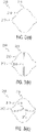
- FIG. 3 is a cross-sectional view of a unit structure of the non-pneumatic tire of the present invention.
- the cross-sectional shape of the unit structure 210 of the spoke unit 200 has a longitudinal protrusion 211 and a transverse protrusion 212.
- an inflection point 213 is formed at a line connecting the longitudinal protrusion 211 and the transverse protrusion 212.
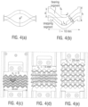
- This shape provides a cushion structure enabling each of the unit structures 210 to absorb shock, as shown in FIG. 4 .
- the inflection point 213, as shown in FIGS. 4(a) and 4(b) makes repeated bending behavior of the longitudinal protrusion 211 smoother.
- FIGS. 4(c), (d) , and (3) are pictures taken to check what bending behavior the unit structures 210 shows under up-down pressure.
- a longitudinal separation wall 214 may be formed at the center portion of the unit structure 210.
- the longitudinal separation wall 214 can increase the vertical rigidity of the unit structure 210. Further, air pressure that is obtained by injecting air is not applied to the tire of the present invention, but the tube-shaped space formed by the unit structure 210 is filled with air. Accordingly, the longitudinal separation wall 214 increases the rigidity of the unit structure 210 by suppressing airflow.
- a transverse separation wall 215 may be formed at the center portion of the unit structure 210. It is preferable to form a protrusion 216 at the center of the transverse separation wall 215.
- the transverse separation wall 215 can not only further increase the rigidity of the unit structure 210 by suppressing airflow, as described above, but guide uniform contraction shape of the unit structure 210 under pressure using the protrusion 216.
- a side wall of the transverse protrusion 212 of the outer unit structure 210 of the spoke unit 200 protrudes, thereby forming circumferential ridge 220 and groove 230.
- the unit structure of the present invention are not formed in the axial direction but form a tube structure in the circumferential direction. Accordingly, a side wall of the transverse protrusion 212 of the outer unit structure 210 of the spoke unit 200 protrudes, thereby forming circumferential ridge 220 and groove 230.
- This configuration provides remarkably high air resistance ability in comparison to the non-pneumatic tire having a web spoke open in the axial direction in the related art. Further, an additional effect of improving the external aesthetic appearance of the tire can be expected from the ridge 220 and the groove 230.
- the unit structures 210 of the spoke unit 200 are arranged 5 by 8 transversely and longitudinally, respectively, between the tread 100 and the rim 300. Further, it is preferable that the longitudinal separation wall 214 is formed at the upper two lines of unit structures 210 adjacent to the tread 100 and lower three lines of unit structures 210 adjacent to the rim 300, that the transverse separation wall 215 is formed at three middle lines between the upper two lines and the lower three lines, and that the transverse separation wall 215 has the protrusion 216 at the center. This is an optimal configuration derived in consideration of the material of the spoke unit 200 and the load that is generally applied to the tires of passenger vehicles.
- FIG. 5 is a view illustrating behavior by force that is applied when the non-pneumatic tire of the present invention is operated.
- FIG. 5(a) shows a state when load is not applied and
- FIG. 5(b) shows a state when the tire is mounted to a vehicle and receives the load of the vehicle.
- FIG. 5(c) shows a driving state in cornering or on an inclined road surface.
- the unit structure 210 of the present invention is individually deformed in response to pressure in accordance with the state of a road surface and appropriately distributes load in accordance with a required level.
- the total width of the lower three lines of unit structures is smaller than the total width of the middle three lines of unit structures. This is for improving structural density because greater load is applied to the portion close to the rim 300.
- the present invention is intended to improve the performance of a non-pneumatic tire for improving maneuverability and riding comfort by applying and using a structural reinforcing material structure that is advantageous in terms as steering performance and vibration absorption in cornering of a tire structurally supporting the load of a vehicle.
- the present invention has sufficient structural rigidity as a non-pneumatic tire, so it is possible to sufficiently support the load of a vehicle and expect an effect of maximizing harmony of the steering characteristic and the riding comfort characteristic.
- the non-pneumatic tire of the present invention uses a meta structure, so meta concept provides strong supporting force and smooth shock absorption effect using a structural meta-material, and there is no possibility of flat tire because it is a non-pneumatic tire that does not need injection of air.
- structural density is increased at the portion around the grounding surface and the portions around the surface being in contact with the shaft of a wheel in order to increase supporting force when the structure is applied. Accordingly, it is possible to increase the supporting force on a road surface and smoothly absorb various kinds of shock.
- the closed structure at a side wall is advantageous in terms of noise reduction, as compared with the spoke type NPT of the related art, and can expect an effect of improving aesthetic external appearance by implementing a new NPT structure.
- the present invention is intended to improve the performance of a non-pneumatic tire for improving maneuverability and riding comfort by applying and using a structural reinforcing material structure that is advantageous in terms as steering performance and vibration absorption in cornering of a tire structurally supporting the load of a vehicle.
- the non-pneumatic tire has an asymmetric spoke structure, as compared with spokes of the related art, and a tube-shaped reinforcing material structure so it has sufficient structural rigidity as a non-pneumatic tire. According to this configuration, it is possible to sufficiently support the load of a vehicle and expect an effect of maximizing harmony of the steering characteristic and the riding comfort characteristic.
Landscapes
- Engineering & Computer Science (AREA)
- Mechanical Engineering (AREA)
- Tires In General (AREA)
Claims (7)
- Pneu non pneumatique comprenant une bande de roulement (100) qui entre en contact avec le sol, une jante (300) qui est connectée à un essieu, et une unité de rayon (200) qui fonctionne comme un support structurel entre la jante (300) et la bande de roulement (100), dans lequel l'unité de rayon (200) est formée dans une méta-structure dans laquelle sont répétées des structures unitaires (210),dans lequel chaque structure unitaire (210) de l'unité de rayon (200) présente une forme de tube présentant une cavité dans la direction circonférentielle du pneu,dans lequel une forme en coupe transversale de la cavité de la structure unitaire (210) de l'unité de rayon (200) présente deux saillies longitudinales (211) dans une direction longitudinale entre la jante (300) et la bande de roulement (100) et deux saillies transversales (212) dans une direction transversale perpendiculaire à la direction longitudinale,le pneu non pneumatique étant caractérisé par le fait qu'un point d'inflexion (213) est formé au niveau d'une ligne connectant une des saillies longitudinales (211) et une des saillies transversales (212) de chacune des structures unitaires (210).
- Pneu non pneumatique selon la revendication 1, dans lequel une paroi de séparation longitudinale (214) est formée au niveau d'une partie centrale de la structure unitaire (210), dans lequel ladite paroi de séparation longitudinale (214) s'étend dans la direction longitudinale entre la jante (300) et la bande de roulement (100) et connecte les deux saillies longitudinales (211).
- Pneu non pneumatique selon la revendication 1, dans lequel une paroi de séparation transversale (215) est formée au niveau de la partie centrale de la structure unitaire (210), dans lequel ladite paroi de séparation transversale (215) s'étend dans la direction transversale et connecte les deux saillies transversales (212).
- Pneu non pneumatique selon la revendication 3, dans lequel la paroi de séparation transversale (215) présente une saillie (216) au niveau de sa partie centrale.
- Pneu non pneumatique selon la revendication 1, dans lequel les saillies transversales (212) des structures unitaires (210) de l'unité de rayon (200) sont situées au niveau de deux parois latérales extérieures dans la direction transversale du pneu non pneumatique et s'étendent dans la direction circonférentielle du pneu non pneumatique pour former une pluralité d'arêtes circonférentielles saillant vers l'extérieur (220) des deux parois latérales, dans lequel des rainures circonférentielles (230) sont formées dans chacune des deux parois latérales du pneu non pneumatique entre des paires adjacentes de la pluralité d'arêtes circonférentielles faisant saillie vers l'extérieur (220).
- Pneu non pneumatique selon la revendication 5, dans lequel les structures unitaires (210) de l'unité de rayon (200) sont disposées à raison de 5 par 8 dans respectivement la direction transversale et la direction longitudinale entre la bande de roulement (100) et la jante (300).
- Pneu non pneumatique selon la revendication 6, dans lequel une paroi de séparation longitudinale (214) s'étendant dans la direction longitudinale et connectant les deux saillies longitudinales (211) est formée au niveau des deux lignes supérieures des structures unitaires (210) adjacentes à la bande de roulement (100) et des trois lignes inférieures des structures unitaires (210) adjacentes à la jante (300), une paroi de séparation transversale (215) s'étendant dans la direction transversale et connectant les deux saillies transversales (212) est formée au niveau de trois lignes médianes entre les deux lignes supérieures et les trois lignes inférieures, et la paroi de séparation transversale (215) présente une saillie (216) en son centre.
Applications Claiming Priority (1)
| Application Number | Priority Date | Filing Date | Title |
|---|---|---|---|
| KR1020180134661A KR102127668B1 (ko) | 2018-11-05 | 2018-11-05 | 비공기입 타이어 |
Publications (2)
| Publication Number | Publication Date |
|---|---|
| EP3686032A1 EP3686032A1 (fr) | 2020-07-29 |
| EP3686032B1 true EP3686032B1 (fr) | 2023-03-01 |
Family
ID=68470264
Family Applications (1)
| Application Number | Title | Priority Date | Filing Date |
|---|---|---|---|
| EP19207251.0A Active EP3686032B1 (fr) | 2018-11-05 | 2019-11-05 | Pneu non pneumatique |
Country Status (5)
| Country | Link |
|---|---|
| US (1) | US11571932B2 (fr) |
| EP (1) | EP3686032B1 (fr) |
| JP (1) | JP6907287B2 (fr) |
| KR (1) | KR102127668B1 (fr) |
| CN (1) | CN111137069B (fr) |
Families Citing this family (5)
| Publication number | Priority date | Publication date | Assignee | Title |
|---|---|---|---|---|
| US11351818B2 (en) | 2020-07-14 | 2022-06-07 | Sun T. Hong | Spiral spring wheel |
| US12427809B2 (en) | 2020-11-19 | 2025-09-30 | Regents Of The University Of Minnesota | Non-pneumatic tire |
| CN113942345A (zh) * | 2021-10-22 | 2022-01-18 | 芜湖集拓实心胎有限公司 | 一种能够适应恶劣环境的实心胎 |
| CN114312151B (zh) * | 2022-01-20 | 2025-07-11 | 深圳市道瑞轮胎有限公司 | 免充气式轮胎 |
| KR102745366B1 (ko) * | 2022-09-27 | 2024-12-20 | 금호타이어 주식회사 | 공기입 타이어 |
Family Cites Families (23)
| Publication number | Priority date | Publication date | Assignee | Title |
|---|---|---|---|---|
| US1343684A (en) * | 1920-06-15 | Wheel-cushion and means for mounting same | ||
| US2620845A (en) * | 1949-05-09 | 1952-12-09 | Lord Mfg Co | Cushioned tire |
| JPS477452Y1 (fr) * | 1969-06-16 | 1972-03-21 | ||
| JPS5963203A (ja) * | 1982-09-02 | 1984-04-10 | ソシエテ・デ・デベロップメント・テクノロジック・エス・ア− | 空気圧不要タイヤ用インサ−トチユ−ブ |
| US4471827A (en) * | 1983-01-05 | 1984-09-18 | Czapar W A | Non-pneumatic insert tube for tires |
| AU546559B2 (en) * | 1982-09-02 | 1985-09-05 | William A. Czapar | Non-pneumatic insert tube for tyres |
| JPS63902U (fr) * | 1986-06-23 | 1988-01-06 | ||
| JPH0328004U (fr) * | 1989-07-28 | 1991-03-20 | ||
| WO2003018332A1 (fr) | 2001-08-24 | 2003-03-06 | Societe De Technologie Michelin | Pneu non pneumatique |
| JP2004210016A (ja) * | 2002-12-27 | 2004-07-29 | Honda Motor Co Ltd | タイヤ |
| US7546862B2 (en) | 2005-05-06 | 2009-06-16 | New Tech Tire Llc | Non-pneumatic vehicle tire |
| FR2875437B1 (fr) | 2004-09-23 | 2006-11-24 | Conception & Dev Michelin Sa | Bandage flexible non pneumatique |
| US8544515B2 (en) * | 2008-11-10 | 2013-10-01 | Mkp Structural Design Associates, Inc. | Ultralightweight runflat tires based upon negative poisson ratio (NPR) auxetic structures |
| KR20100090015A (ko) | 2009-02-05 | 2010-08-13 | 엘지디스플레이 주식회사 | 태양전지 및 그 제조방법 |
| US8999480B2 (en) * | 2010-04-01 | 2015-04-07 | Compagnie Generale Des Etablissements Michelin | Chiral honeycomb meso-structures for shear flexure |
| CN104118276B (zh) * | 2014-07-08 | 2016-08-10 | 清华大学 | 一种空间桁架式免充气轮胎 |
| US10035385B2 (en) * | 2015-03-03 | 2018-07-31 | The Goodyear Tire & Rubber Company | Tire producing electrical power |
| CN204472454U (zh) * | 2015-03-11 | 2015-07-15 | 山东玲珑轮胎股份有限公司 | 一种非充气轮胎 |
| CN104999862B (zh) * | 2015-06-26 | 2017-02-01 | 青岛科技大学 | 免充气安全轮胎 |
| KR101725229B1 (ko) | 2015-08-27 | 2017-04-17 | 나영민 | 비 공기압 타이어 |
| US20170080756A1 (en) | 2015-09-17 | 2017-03-23 | The Goodyear Tire & Rubber Company | Non-pneumatic tire |
| KR101796231B1 (ko) * | 2016-07-29 | 2017-12-01 | 금호타이어 주식회사 | 비공기입 타이어 |
| KR101977349B1 (ko) * | 2017-11-16 | 2019-05-10 | 금호타이어 주식회사 | 비공기입 타이어 제작방법 |
-
2018
- 2018-11-05 KR KR1020180134661A patent/KR102127668B1/ko active Active
-
2019
- 2019-11-04 US US16/673,801 patent/US11571932B2/en active Active
- 2019-11-05 EP EP19207251.0A patent/EP3686032B1/fr active Active
- 2019-11-05 JP JP2019200765A patent/JP6907287B2/ja active Active
- 2019-11-05 CN CN201911071744.1A patent/CN111137069B/zh active Active
Also Published As
| Publication number | Publication date |
|---|---|
| KR102127668B1 (ko) | 2020-06-30 |
| CN111137069B (zh) | 2022-03-22 |
| JP2020075715A (ja) | 2020-05-21 |
| EP3686032A1 (fr) | 2020-07-29 |
| CN111137069A (zh) | 2020-05-12 |
| KR20200051909A (ko) | 2020-05-14 |
| US20200139763A1 (en) | 2020-05-07 |
| US11571932B2 (en) | 2023-02-07 |
| JP6907287B2 (ja) | 2021-07-21 |
Similar Documents
| Publication | Publication Date | Title |
|---|---|---|
| EP3686032B1 (fr) | Pneu non pneumatique | |
| EP3647075B1 (fr) | Pneu non pneumatique | |
| US9333799B2 (en) | Non-pneumatic tire with reinforcing member having plate wire structure | |
| EP2679406B1 (fr) | Pneu sans air | |
| KR101362120B1 (ko) | 에어리스 타이어 | |
| US20140062171A1 (en) | Non-pneumatic tire | |
| JPS62295704A (ja) | 低振動非空気式タイヤ | |
| JPWO2007057975A1 (ja) | 弾性構造体タイヤ | |
| US20140062172A1 (en) | Non-pneumatic tire | |
| KR20220090613A (ko) | 내구성이 향상된 비공기입 타이어 | |
| KR101301579B1 (ko) | 비공기압 타이어 | |
| KR101670585B1 (ko) | 비공기압 타이어 | |
| KR102183211B1 (ko) | 비공기압 타이어 | |
| KR102312931B1 (ko) | 차량용 비공기입 타이어 및 이의 제조방법 | |
| KR102656639B1 (ko) | 비공기입 타이어 | |
| KR101147859B1 (ko) | 사이드부를 보강한 비공기입 타이어 | |
| KR20230019706A (ko) | 비공기입 타이어 | |
| KR102495867B1 (ko) | 비공기입 타이어의 스포크 구조체 | |
| KR102823277B1 (ko) | 교차 부재가 포함된 스포크를 구비하는 비공기입 타이어 | |
| JP2019116167A (ja) | 空気入りタイヤ | |
| JPH0211441B2 (fr) | ||
| KR20250039643A (ko) | 스포크를 구비한 비공기입 타이어 | |
| JP2006117057A (ja) | 弾性車輪 |
Legal Events
| Date | Code | Title | Description |
|---|---|---|---|
| PUAI | Public reference made under article 153(3) epc to a published international application that has entered the european phase |
Free format text: ORIGINAL CODE: 0009012 |
|
| STAA | Information on the status of an ep patent application or granted ep patent |
Free format text: STATUS: REQUEST FOR EXAMINATION WAS MADE |
|
| 17P | Request for examination filed |
Effective date: 20191105 |
|
| AK | Designated contracting states |
Kind code of ref document: A1 Designated state(s): AL AT BE BG CH CY CZ DE DK EE ES FI FR GB GR HR HU IE IS IT LI LT LU LV MC MK MT NL NO PL PT RO RS SE SI SK SM TR |
|
| AX | Request for extension of the european patent |
Extension state: BA ME |
|
| STAA | Information on the status of an ep patent application or granted ep patent |
Free format text: STATUS: EXAMINATION IS IN PROGRESS |
|
| 17Q | First examination report despatched |
Effective date: 20210510 |
|
| GRAP | Despatch of communication of intention to grant a patent |
Free format text: ORIGINAL CODE: EPIDOSNIGR1 |
|
| STAA | Information on the status of an ep patent application or granted ep patent |
Free format text: STATUS: GRANT OF PATENT IS INTENDED |
|
| INTG | Intention to grant announced |
Effective date: 20220909 |
|
| GRAS | Grant fee paid |
Free format text: ORIGINAL CODE: EPIDOSNIGR3 |
|
| GRAA | (expected) grant |
Free format text: ORIGINAL CODE: 0009210 |
|
| STAA | Information on the status of an ep patent application or granted ep patent |
Free format text: STATUS: THE PATENT HAS BEEN GRANTED |
|
| AK | Designated contracting states |
Kind code of ref document: B1 Designated state(s): AL AT BE BG CH CY CZ DE DK EE ES FI FR GB GR HR HU IE IS IT LI LT LU LV MC MK MT NL NO PL PT RO RS SE SI SK SM TR |
|
| REG | Reference to a national code |
Ref country code: GB Ref legal event code: FG4D |
|
| REG | Reference to a national code |
Ref country code: CH Ref legal event code: EP Ref country code: AT Ref legal event code: REF Ref document number: 1550729 Country of ref document: AT Kind code of ref document: T Effective date: 20230315 |
|
| REG | Reference to a national code |
Ref country code: DE Ref legal event code: R096 Ref document number: 602019025778 Country of ref document: DE |
|
| REG | Reference to a national code |
Ref country code: IE Ref legal event code: FG4D |
|
| REG | Reference to a national code |
Ref country code: LT Ref legal event code: MG9D |
|
| REG | Reference to a national code |
Ref country code: NL Ref legal event code: MP Effective date: 20230301 |
|
| PG25 | Lapsed in a contracting state [announced via postgrant information from national office to epo] |
Ref country code: RS Free format text: LAPSE BECAUSE OF FAILURE TO SUBMIT A TRANSLATION OF THE DESCRIPTION OR TO PAY THE FEE WITHIN THE PRESCRIBED TIME-LIMIT Effective date: 20230301 Ref country code: NO Free format text: LAPSE BECAUSE OF FAILURE TO SUBMIT A TRANSLATION OF THE DESCRIPTION OR TO PAY THE FEE WITHIN THE PRESCRIBED TIME-LIMIT Effective date: 20230601 Ref country code: LV Free format text: LAPSE BECAUSE OF FAILURE TO SUBMIT A TRANSLATION OF THE DESCRIPTION OR TO PAY THE FEE WITHIN THE PRESCRIBED TIME-LIMIT Effective date: 20230301 Ref country code: LT Free format text: LAPSE BECAUSE OF FAILURE TO SUBMIT A TRANSLATION OF THE DESCRIPTION OR TO PAY THE FEE WITHIN THE PRESCRIBED TIME-LIMIT Effective date: 20230301 Ref country code: HR Free format text: LAPSE BECAUSE OF FAILURE TO SUBMIT A TRANSLATION OF THE DESCRIPTION OR TO PAY THE FEE WITHIN THE PRESCRIBED TIME-LIMIT Effective date: 20230301 Ref country code: ES Free format text: LAPSE BECAUSE OF FAILURE TO SUBMIT A TRANSLATION OF THE DESCRIPTION OR TO PAY THE FEE WITHIN THE PRESCRIBED TIME-LIMIT Effective date: 20230301 |
|
| REG | Reference to a national code |
Ref country code: AT Ref legal event code: MK05 Ref document number: 1550729 Country of ref document: AT Kind code of ref document: T Effective date: 20230301 |
|
| PG25 | Lapsed in a contracting state [announced via postgrant information from national office to epo] |
Ref country code: SE Free format text: LAPSE BECAUSE OF FAILURE TO SUBMIT A TRANSLATION OF THE DESCRIPTION OR TO PAY THE FEE WITHIN THE PRESCRIBED TIME-LIMIT Effective date: 20230301 Ref country code: PL Free format text: LAPSE BECAUSE OF FAILURE TO SUBMIT A TRANSLATION OF THE DESCRIPTION OR TO PAY THE FEE WITHIN THE PRESCRIBED TIME-LIMIT Effective date: 20230301 Ref country code: NL Free format text: LAPSE BECAUSE OF FAILURE TO SUBMIT A TRANSLATION OF THE DESCRIPTION OR TO PAY THE FEE WITHIN THE PRESCRIBED TIME-LIMIT Effective date: 20230301 Ref country code: GR Free format text: LAPSE BECAUSE OF FAILURE TO SUBMIT A TRANSLATION OF THE DESCRIPTION OR TO PAY THE FEE WITHIN THE PRESCRIBED TIME-LIMIT Effective date: 20230602 Ref country code: FI Free format text: LAPSE BECAUSE OF FAILURE TO SUBMIT A TRANSLATION OF THE DESCRIPTION OR TO PAY THE FEE WITHIN THE PRESCRIBED TIME-LIMIT Effective date: 20230301 |
|
| PG25 | Lapsed in a contracting state [announced via postgrant information from national office to epo] |
Ref country code: SM Free format text: LAPSE BECAUSE OF FAILURE TO SUBMIT A TRANSLATION OF THE DESCRIPTION OR TO PAY THE FEE WITHIN THE PRESCRIBED TIME-LIMIT Effective date: 20230301 Ref country code: RO Free format text: LAPSE BECAUSE OF FAILURE TO SUBMIT A TRANSLATION OF THE DESCRIPTION OR TO PAY THE FEE WITHIN THE PRESCRIBED TIME-LIMIT Effective date: 20230301 Ref country code: PT Free format text: LAPSE BECAUSE OF FAILURE TO SUBMIT A TRANSLATION OF THE DESCRIPTION OR TO PAY THE FEE WITHIN THE PRESCRIBED TIME-LIMIT Effective date: 20230703 Ref country code: EE Free format text: LAPSE BECAUSE OF FAILURE TO SUBMIT A TRANSLATION OF THE DESCRIPTION OR TO PAY THE FEE WITHIN THE PRESCRIBED TIME-LIMIT Effective date: 20230301 Ref country code: CZ Free format text: LAPSE BECAUSE OF FAILURE TO SUBMIT A TRANSLATION OF THE DESCRIPTION OR TO PAY THE FEE WITHIN THE PRESCRIBED TIME-LIMIT Effective date: 20230301 Ref country code: AT Free format text: LAPSE BECAUSE OF FAILURE TO SUBMIT A TRANSLATION OF THE DESCRIPTION OR TO PAY THE FEE WITHIN THE PRESCRIBED TIME-LIMIT Effective date: 20230301 |
|
| PG25 | Lapsed in a contracting state [announced via postgrant information from national office to epo] |
Ref country code: SK Free format text: LAPSE BECAUSE OF FAILURE TO SUBMIT A TRANSLATION OF THE DESCRIPTION OR TO PAY THE FEE WITHIN THE PRESCRIBED TIME-LIMIT Effective date: 20230301 Ref country code: IS Free format text: LAPSE BECAUSE OF FAILURE TO SUBMIT A TRANSLATION OF THE DESCRIPTION OR TO PAY THE FEE WITHIN THE PRESCRIBED TIME-LIMIT Effective date: 20230701 |
|
| REG | Reference to a national code |
Ref country code: DE Ref legal event code: R097 Ref document number: 602019025778 Country of ref document: DE |
|
| PLBE | No opposition filed within time limit |
Free format text: ORIGINAL CODE: 0009261 |
|
| STAA | Information on the status of an ep patent application or granted ep patent |
Free format text: STATUS: NO OPPOSITION FILED WITHIN TIME LIMIT |
|
| PG25 | Lapsed in a contracting state [announced via postgrant information from national office to epo] |
Ref country code: SI Free format text: LAPSE BECAUSE OF FAILURE TO SUBMIT A TRANSLATION OF THE DESCRIPTION OR TO PAY THE FEE WITHIN THE PRESCRIBED TIME-LIMIT Effective date: 20230301 Ref country code: DK Free format text: LAPSE BECAUSE OF FAILURE TO SUBMIT A TRANSLATION OF THE DESCRIPTION OR TO PAY THE FEE WITHIN THE PRESCRIBED TIME-LIMIT Effective date: 20230301 |
|
| 26N | No opposition filed |
Effective date: 20231204 |
|
| PG25 | Lapsed in a contracting state [announced via postgrant information from national office to epo] |
Ref country code: IT Free format text: LAPSE BECAUSE OF FAILURE TO SUBMIT A TRANSLATION OF THE DESCRIPTION OR TO PAY THE FEE WITHIN THE PRESCRIBED TIME-LIMIT Effective date: 20230301 |
|
| REG | Reference to a national code |
Ref country code: DE Ref legal event code: R119 Ref document number: 602019025778 Country of ref document: DE |
|
| REG | Reference to a national code |
Ref country code: CH Ref legal event code: PL |
|
| PG25 | Lapsed in a contracting state [announced via postgrant information from national office to epo] |
Ref country code: MC Free format text: LAPSE BECAUSE OF FAILURE TO SUBMIT A TRANSLATION OF THE DESCRIPTION OR TO PAY THE FEE WITHIN THE PRESCRIBED TIME-LIMIT Effective date: 20230301 |
|
| PG25 | Lapsed in a contracting state [announced via postgrant information from national office to epo] |
Ref country code: LU Free format text: LAPSE BECAUSE OF NON-PAYMENT OF DUE FEES Effective date: 20231105 |
|
| PG25 | Lapsed in a contracting state [announced via postgrant information from national office to epo] |
Ref country code: CH Free format text: LAPSE BECAUSE OF NON-PAYMENT OF DUE FEES Effective date: 20231130 |
|
| GBPC | Gb: european patent ceased through non-payment of renewal fee |
Effective date: 20231105 |
|
| PG25 | Lapsed in a contracting state [announced via postgrant information from national office to epo] |
Ref country code: MC Free format text: LAPSE BECAUSE OF FAILURE TO SUBMIT A TRANSLATION OF THE DESCRIPTION OR TO PAY THE FEE WITHIN THE PRESCRIBED TIME-LIMIT Effective date: 20230301 Ref country code: LU Free format text: LAPSE BECAUSE OF NON-PAYMENT OF DUE FEES Effective date: 20231105 Ref country code: CH Free format text: LAPSE BECAUSE OF NON-PAYMENT OF DUE FEES Effective date: 20231130 |
|
| REG | Reference to a national code |
Ref country code: BE Ref legal event code: MM Effective date: 20231130 |
|
| REG | Reference to a national code |
Ref country code: IE Ref legal event code: MM4A |
|
| PG25 | Lapsed in a contracting state [announced via postgrant information from national office to epo] |
Ref country code: DE Free format text: LAPSE BECAUSE OF NON-PAYMENT OF DUE FEES Effective date: 20240601 Ref country code: IE Free format text: LAPSE BECAUSE OF NON-PAYMENT OF DUE FEES Effective date: 20231105 |
|
| PG25 | Lapsed in a contracting state [announced via postgrant information from national office to epo] |
Ref country code: GB Free format text: LAPSE BECAUSE OF NON-PAYMENT OF DUE FEES Effective date: 20231105 |
|
| PG25 | Lapsed in a contracting state [announced via postgrant information from national office to epo] |
Ref country code: BE Free format text: LAPSE BECAUSE OF NON-PAYMENT OF DUE FEES Effective date: 20231130 |
|
| PG25 | Lapsed in a contracting state [announced via postgrant information from national office to epo] |
Ref country code: FR Free format text: LAPSE BECAUSE OF NON-PAYMENT OF DUE FEES Effective date: 20231130 |
|
| PG25 | Lapsed in a contracting state [announced via postgrant information from national office to epo] |
Ref country code: IE Free format text: LAPSE BECAUSE OF NON-PAYMENT OF DUE FEES Effective date: 20231105 Ref country code: GB Free format text: LAPSE BECAUSE OF NON-PAYMENT OF DUE FEES Effective date: 20231105 Ref country code: FR Free format text: LAPSE BECAUSE OF NON-PAYMENT OF DUE FEES Effective date: 20231130 Ref country code: DE Free format text: LAPSE BECAUSE OF NON-PAYMENT OF DUE FEES Effective date: 20240601 Ref country code: BE Free format text: LAPSE BECAUSE OF NON-PAYMENT OF DUE FEES Effective date: 20231130 |
|
| PG25 | Lapsed in a contracting state [announced via postgrant information from national office to epo] |
Ref country code: BG Free format text: LAPSE BECAUSE OF FAILURE TO SUBMIT A TRANSLATION OF THE DESCRIPTION OR TO PAY THE FEE WITHIN THE PRESCRIBED TIME-LIMIT Effective date: 20230301 |
|
| PG25 | Lapsed in a contracting state [announced via postgrant information from national office to epo] |
Ref country code: BG Free format text: LAPSE BECAUSE OF FAILURE TO SUBMIT A TRANSLATION OF THE DESCRIPTION OR TO PAY THE FEE WITHIN THE PRESCRIBED TIME-LIMIT Effective date: 20230301 |
|
| PG25 | Lapsed in a contracting state [announced via postgrant information from national office to epo] |
Ref country code: CY Free format text: LAPSE BECAUSE OF FAILURE TO SUBMIT A TRANSLATION OF THE DESCRIPTION OR TO PAY THE FEE WITHIN THE PRESCRIBED TIME-LIMIT; INVALID AB INITIO Effective date: 20191105 |
|
| PG25 | Lapsed in a contracting state [announced via postgrant information from national office to epo] |
Ref country code: HU Free format text: LAPSE BECAUSE OF FAILURE TO SUBMIT A TRANSLATION OF THE DESCRIPTION OR TO PAY THE FEE WITHIN THE PRESCRIBED TIME-LIMIT; INVALID AB INITIO Effective date: 20191105 |
|
| PG25 | Lapsed in a contracting state [announced via postgrant information from national office to epo] |
Ref country code: TR Free format text: LAPSE BECAUSE OF FAILURE TO SUBMIT A TRANSLATION OF THE DESCRIPTION OR TO PAY THE FEE WITHIN THE PRESCRIBED TIME-LIMIT Effective date: 20230301 |