EP3686047A1 - Câble de charge - Google Patents
Câble de charge Download PDFInfo
- Publication number
- EP3686047A1 EP3686047A1 EP19215153.8A EP19215153A EP3686047A1 EP 3686047 A1 EP3686047 A1 EP 3686047A1 EP 19215153 A EP19215153 A EP 19215153A EP 3686047 A1 EP3686047 A1 EP 3686047A1
- Authority
- EP
- European Patent Office
- Prior art keywords
- connection element
- charging cable
- charging
- rectifier
- cable according
- Prior art date
- Legal status (The legal status is an assumption and is not a legal conclusion. Google has not performed a legal analysis and makes no representation as to the accuracy of the status listed.)
- Ceased
Links
Images

Classifications
-
- B—PERFORMING OPERATIONS; TRANSPORTING
- B60—VEHICLES IN GENERAL
- B60L—PROPULSION OF ELECTRICALLY-PROPELLED VEHICLES; SUPPLYING ELECTRIC POWER FOR AUXILIARY EQUIPMENT OF ELECTRICALLY-PROPELLED VEHICLES; ELECTRODYNAMIC BRAKE SYSTEMS FOR VEHICLES IN GENERAL; MAGNETIC SUSPENSION OR LEVITATION FOR VEHICLES; MONITORING OPERATING VARIABLES OF ELECTRICALLY-PROPELLED VEHICLES; ELECTRIC SAFETY DEVICES FOR ELECTRICALLY-PROPELLED VEHICLES
- B60L53/00—Methods of charging batteries, specially adapted for electric vehicles; Charging stations or on-board charging equipment therefor; Exchange of energy storage elements in electric vehicles
- B60L53/10—Methods of charging batteries, specially adapted for electric vehicles; Charging stations or on-board charging equipment therefor; Exchange of energy storage elements in electric vehicles characterised by the energy transfer between the charging station and the vehicle
- B60L53/14—Conductive energy transfer
- B60L53/18—Cables specially adapted for charging electric vehicles
-
- B—PERFORMING OPERATIONS; TRANSPORTING
- B60—VEHICLES IN GENERAL
- B60L—PROPULSION OF ELECTRICALLY-PROPELLED VEHICLES; SUPPLYING ELECTRIC POWER FOR AUXILIARY EQUIPMENT OF ELECTRICALLY-PROPELLED VEHICLES; ELECTRODYNAMIC BRAKE SYSTEMS FOR VEHICLES IN GENERAL; MAGNETIC SUSPENSION OR LEVITATION FOR VEHICLES; MONITORING OPERATING VARIABLES OF ELECTRICALLY-PROPELLED VEHICLES; ELECTRIC SAFETY DEVICES FOR ELECTRICALLY-PROPELLED VEHICLES
- B60L53/00—Methods of charging batteries, specially adapted for electric vehicles; Charging stations or on-board charging equipment therefor; Exchange of energy storage elements in electric vehicles
- B60L53/10—Methods of charging batteries, specially adapted for electric vehicles; Charging stations or on-board charging equipment therefor; Exchange of energy storage elements in electric vehicles characterised by the energy transfer between the charging station and the vehicle
- B60L53/14—Conductive energy transfer
- B60L53/16—Connectors, e.g. plugs or sockets, specially adapted for charging electric vehicles
-
- B—PERFORMING OPERATIONS; TRANSPORTING
- B60—VEHICLES IN GENERAL
- B60L—PROPULSION OF ELECTRICALLY-PROPELLED VEHICLES; SUPPLYING ELECTRIC POWER FOR AUXILIARY EQUIPMENT OF ELECTRICALLY-PROPELLED VEHICLES; ELECTRODYNAMIC BRAKE SYSTEMS FOR VEHICLES IN GENERAL; MAGNETIC SUSPENSION OR LEVITATION FOR VEHICLES; MONITORING OPERATING VARIABLES OF ELECTRICALLY-PROPELLED VEHICLES; ELECTRIC SAFETY DEVICES FOR ELECTRICALLY-PROPELLED VEHICLES
- B60L53/00—Methods of charging batteries, specially adapted for electric vehicles; Charging stations or on-board charging equipment therefor; Exchange of energy storage elements in electric vehicles
- B60L53/60—Monitoring or controlling charging stations
-
- H—ELECTRICITY
- H01—ELECTRIC ELEMENTS
- H01R—ELECTRICALLY-CONDUCTIVE CONNECTIONS; STRUCTURAL ASSOCIATIONS OF A PLURALITY OF MUTUALLY-INSULATED ELECTRICAL CONNECTING ELEMENTS; COUPLING DEVICES; CURRENT COLLECTORS
- H01R13/00—Details of coupling devices of the kinds covered by groups H01R12/70 or H01R24/00 - H01R33/00
- H01R13/66—Structural association with built-in electrical component
- H01R13/665—Structural association with built-in electrical component with built-in electronic circuit
- H01R13/6683—Structural association with built-in electrical component with built-in electronic circuit with built-in sensor
-
- H—ELECTRICITY
- H02—GENERATION; CONVERSION OR DISTRIBUTION OF ELECTRIC POWER
- H02J—ELECTRIC POWER NETWORKS; CIRCUIT ARRANGEMENTS OR SYSTEMS FOR SUPPLYING OR DISTRIBUTING ELECTRIC POWER; SYSTEMS FOR STORING ELECTRIC ENERGY
- H02J7/00—Circuit arrangements for charging or discharging batteries or for supplying loads from batteries
- H02J7/50—Circuit arrangements for charging or discharging batteries or for supplying loads from batteries acting upon multiple batteries simultaneously or sequentially
-
- H—ELECTRICITY
- H02—GENERATION; CONVERSION OR DISTRIBUTION OF ELECTRIC POWER
- H02J—ELECTRIC POWER NETWORKS; CIRCUIT ARRANGEMENTS OR SYSTEMS FOR SUPPLYING OR DISTRIBUTING ELECTRIC POWER; SYSTEMS FOR STORING ELECTRIC ENERGY
- H02J7/00—Circuit arrangements for charging or discharging batteries or for supplying loads from batteries
- H02J7/60—Circuit arrangements for charging or discharging batteries or for supplying loads from batteries including safety or protection arrangements
-
- H—ELECTRICITY
- H02—GENERATION; CONVERSION OR DISTRIBUTION OF ELECTRIC POWER
- H02J—ELECTRIC POWER NETWORKS; CIRCUIT ARRANGEMENTS OR SYSTEMS FOR SUPPLYING OR DISTRIBUTING ELECTRIC POWER; SYSTEMS FOR STORING ELECTRIC ENERGY
- H02J7/00—Circuit arrangements for charging or discharging batteries or for supplying loads from batteries
- H02J7/60—Circuit arrangements for charging or discharging batteries or for supplying loads from batteries including safety or protection arrangements
- H02J7/663—Circuit arrangements for charging or discharging batteries or for supplying loads from batteries including safety or protection arrangements using battery or load disconnect circuits
-
- H—ELECTRICITY
- H02—GENERATION; CONVERSION OR DISTRIBUTION OF ELECTRIC POWER
- H02J—ELECTRIC POWER NETWORKS; CIRCUIT ARRANGEMENTS OR SYSTEMS FOR SUPPLYING OR DISTRIBUTING ELECTRIC POWER; SYSTEMS FOR STORING ELECTRIC ENERGY
- H02J7/00—Circuit arrangements for charging or discharging batteries or for supplying loads from batteries
- H02J7/90—Regulation of charging or discharging current or voltage
- H02J7/96—Regulation of charging or discharging current or voltage in response to battery voltage
-
- H—ELECTRICITY
- H02—GENERATION; CONVERSION OR DISTRIBUTION OF ELECTRIC POWER
- H02J—ELECTRIC POWER NETWORKS; CIRCUIT ARRANGEMENTS OR SYSTEMS FOR SUPPLYING OR DISTRIBUTING ELECTRIC POWER; SYSTEMS FOR STORING ELECTRIC ENERGY
- H02J7/00—Circuit arrangements for charging or discharging batteries or for supplying loads from batteries
- H02J7/90—Regulation of charging or discharging current or voltage
- H02J7/971—Regulation of charging or discharging current or voltage the charge cycle being controlled or terminated in response to non-electric parameters
- H02J7/975—Regulation of charging or discharging current or voltage the charge cycle being controlled or terminated in response to non-electric parameters in response to temperature
-
- B—PERFORMING OPERATIONS; TRANSPORTING
- B60—VEHICLES IN GENERAL
- B60L—PROPULSION OF ELECTRICALLY-PROPELLED VEHICLES; SUPPLYING ELECTRIC POWER FOR AUXILIARY EQUIPMENT OF ELECTRICALLY-PROPELLED VEHICLES; ELECTRODYNAMIC BRAKE SYSTEMS FOR VEHICLES IN GENERAL; MAGNETIC SUSPENSION OR LEVITATION FOR VEHICLES; MONITORING OPERATING VARIABLES OF ELECTRICALLY-PROPELLED VEHICLES; ELECTRIC SAFETY DEVICES FOR ELECTRICALLY-PROPELLED VEHICLES
- B60L2210/00—Converter types
- B60L2210/30—AC to DC converters
-
- H—ELECTRICITY
- H01—ELECTRIC ELEMENTS
- H01R—ELECTRICALLY-CONDUCTIVE CONNECTIONS; STRUCTURAL ASSOCIATIONS OF A PLURALITY OF MUTUALLY-INSULATED ELECTRICAL CONNECTING ELEMENTS; COUPLING DEVICES; CURRENT COLLECTORS
- H01R13/00—Details of coupling devices of the kinds covered by groups H01R12/70 or H01R24/00 - H01R33/00
- H01R13/66—Structural association with built-in electrical component
- H01R13/70—Structural association with built-in electrical component with built-in switch
- H01R13/713—Structural association with built-in electrical component with built-in switch the switch being a safety switch
- H01R13/7137—Structural association with built-in electrical component with built-in switch the switch being a safety switch with thermal interrupter
-
- H—ELECTRICITY
- H01—ELECTRIC ELEMENTS
- H01R—ELECTRICALLY-CONDUCTIVE CONNECTIONS; STRUCTURAL ASSOCIATIONS OF A PLURALITY OF MUTUALLY-INSULATED ELECTRICAL CONNECTING ELEMENTS; COUPLING DEVICES; CURRENT COLLECTORS
- H01R2201/00—Connectors or connections adapted for particular applications
- H01R2201/26—Connectors or connections adapted for particular applications for vehicles
-
- H—ELECTRICITY
- H01—ELECTRIC ELEMENTS
- H01R—ELECTRICALLY-CONDUCTIVE CONNECTIONS; STRUCTURAL ASSOCIATIONS OF A PLURALITY OF MUTUALLY-INSULATED ELECTRICAL CONNECTING ELEMENTS; COUPLING DEVICES; CURRENT COLLECTORS
- H01R29/00—Coupling parts for selective co-operation with a counterpart in different ways to establish different circuits, e.g. for voltage selection, for series-parallel selection, programmable connectors
-
- H—ELECTRICITY
- H01—ELECTRIC ELEMENTS
- H01R—ELECTRICALLY-CONDUCTIVE CONNECTIONS; STRUCTURAL ASSOCIATIONS OF A PLURALITY OF MUTUALLY-INSULATED ELECTRICAL CONNECTING ELEMENTS; COUPLING DEVICES; CURRENT COLLECTORS
- H01R31/00—Coupling parts supported only by co-operation with counterpart
- H01R31/06—Intermediate parts for linking two coupling parts, e.g. adapter
- H01R31/065—Intermediate parts for linking two coupling parts, e.g. adapter with built-in electric apparatus
-
- Y—GENERAL TAGGING OF NEW TECHNOLOGICAL DEVELOPMENTS; GENERAL TAGGING OF CROSS-SECTIONAL TECHNOLOGIES SPANNING OVER SEVERAL SECTIONS OF THE IPC; TECHNICAL SUBJECTS COVERED BY FORMER USPC CROSS-REFERENCE ART COLLECTIONS [XRACs] AND DIGESTS
- Y02—TECHNOLOGIES OR APPLICATIONS FOR MITIGATION OR ADAPTATION AGAINST CLIMATE CHANGE
- Y02T—CLIMATE CHANGE MITIGATION TECHNOLOGIES RELATED TO TRANSPORTATION
- Y02T10/00—Road transport of goods or passengers
- Y02T10/60—Other road transportation technologies with climate change mitigation effect
- Y02T10/70—Energy storage systems for electromobility, e.g. batteries
-
- Y—GENERAL TAGGING OF NEW TECHNOLOGICAL DEVELOPMENTS; GENERAL TAGGING OF CROSS-SECTIONAL TECHNOLOGIES SPANNING OVER SEVERAL SECTIONS OF THE IPC; TECHNICAL SUBJECTS COVERED BY FORMER USPC CROSS-REFERENCE ART COLLECTIONS [XRACs] AND DIGESTS
- Y02—TECHNOLOGIES OR APPLICATIONS FOR MITIGATION OR ADAPTATION AGAINST CLIMATE CHANGE
- Y02T—CLIMATE CHANGE MITIGATION TECHNOLOGIES RELATED TO TRANSPORTATION
- Y02T10/00—Road transport of goods or passengers
- Y02T10/60—Other road transportation technologies with climate change mitigation effect
- Y02T10/7072—Electromobility specific charging systems or methods for batteries, ultracapacitors, supercapacitors or double-layer capacitors
-
- Y—GENERAL TAGGING OF NEW TECHNOLOGICAL DEVELOPMENTS; GENERAL TAGGING OF CROSS-SECTIONAL TECHNOLOGIES SPANNING OVER SEVERAL SECTIONS OF THE IPC; TECHNICAL SUBJECTS COVERED BY FORMER USPC CROSS-REFERENCE ART COLLECTIONS [XRACs] AND DIGESTS
- Y02—TECHNOLOGIES OR APPLICATIONS FOR MITIGATION OR ADAPTATION AGAINST CLIMATE CHANGE
- Y02T—CLIMATE CHANGE MITIGATION TECHNOLOGIES RELATED TO TRANSPORTATION
- Y02T10/00—Road transport of goods or passengers
- Y02T10/60—Other road transportation technologies with climate change mitigation effect
- Y02T10/72—Electric energy management in electromobility
-
- Y—GENERAL TAGGING OF NEW TECHNOLOGICAL DEVELOPMENTS; GENERAL TAGGING OF CROSS-SECTIONAL TECHNOLOGIES SPANNING OVER SEVERAL SECTIONS OF THE IPC; TECHNICAL SUBJECTS COVERED BY FORMER USPC CROSS-REFERENCE ART COLLECTIONS [XRACs] AND DIGESTS
- Y02—TECHNOLOGIES OR APPLICATIONS FOR MITIGATION OR ADAPTATION AGAINST CLIMATE CHANGE
- Y02T—CLIMATE CHANGE MITIGATION TECHNOLOGIES RELATED TO TRANSPORTATION
- Y02T90/00—Enabling technologies or technologies with a potential or indirect contribution to GHG emissions mitigation
- Y02T90/10—Technologies relating to charging of electric vehicles
- Y02T90/12—Electric charging stations
-
- Y—GENERAL TAGGING OF NEW TECHNOLOGICAL DEVELOPMENTS; GENERAL TAGGING OF CROSS-SECTIONAL TECHNOLOGIES SPANNING OVER SEVERAL SECTIONS OF THE IPC; TECHNICAL SUBJECTS COVERED BY FORMER USPC CROSS-REFERENCE ART COLLECTIONS [XRACs] AND DIGESTS
- Y02—TECHNOLOGIES OR APPLICATIONS FOR MITIGATION OR ADAPTATION AGAINST CLIMATE CHANGE
- Y02T—CLIMATE CHANGE MITIGATION TECHNOLOGIES RELATED TO TRANSPORTATION
- Y02T90/00—Enabling technologies or technologies with a potential or indirect contribution to GHG emissions mitigation
- Y02T90/10—Technologies relating to charging of electric vehicles
- Y02T90/14—Plug-in electric vehicles
Definitions
- the invention relates to a charging cable comprising a rectifier and a first connection element and a second connection element, the first connection element being designed to connect to an energy source external to the vehicle and the second connection element being designed to connect to a charging socket of a motor vehicle comprising an electrical traction energy storage device, the rectifier being used alternating current fed in at the first connection element can be converted into a direct current that can be output at the second connection element.
- Electric vehicles that include an electric traction battery are also referred to as electric vehicles.
- Electric vehicles of this type are generally charged via the general electricity network or the low-voltage network.
- an alternating current or an alternating voltage supplied by the mains must be converted into a direct current or a direct voltage in order to be able to charge the traction battery of the electric vehicle. This conversion can take place, for example, using a charger that includes rectification.
- Direct current charging (DC charging) and alternating current charging (AC charging) are available as charging options for the electric vehicle.
- Electric vehicles suitable for DC charging generally have a DC connection via which they can be connected to a DC charging station external to the vehicle.
- a rectifier rectifying the alternating current used in the power supply is installed in the charging station external to the vehicle.
- an AC connection of the motor vehicle is connected to an AC charging station or an AC power source.
- the alternating current or alternating voltage is rectified via a rectifier installed in the vehicle, which is generally part of a charger installed in the motor vehicle.
- Chargers of this type installed in the motor vehicle typically have charging powers between 3.6 kW and 44 kW.
- external chargers such as those installed in DC charging stations, outputs of up to 350 kW can be achieved.
- AC charging distinguishes between so-called mode 2 charging and so-called mode 3 charging (international standard IEC 61851).
- mode 2 charging in which the motor vehicle is charged at a single-phase or multi-phase AC power source, a cable with an integrated control and protection circuit, for example in the form of an in-cable control box (ICCB), can be used (international standard IEC 62752).
- ICCB in-cable control box
- mode 3 charging a wall box and / or a pedestal is used as the AC power source.
- the respective AC power source is connected to the motor vehicle via a cable with which the AC power source is connected to the charger installed in the motor vehicle.
- the charger in the vehicle is connected to the AC connection or a charging socket of the motor vehicle comprising an AC connection and to the high-voltage DC voltage network of the motor vehicle.
- the device comprises a fixed and a rotatable part, wherein the rotatable part is provided for winding a charging cable with a charging plug and the fixed part has a connection for connection to a power supply.
- the rotatable part and the fixed part are electrically connected to one another via an electrical transformer.
- power electronics are integrated in the winding device, which converts the AC voltage picked up from a three-phase AC voltage network into a DC voltage for charging accumulators and vehicle batteries.
- DE 10 2016 106 840 A1 describes an energy transmission device with an energy intake connection and an energy output connection.
- the device can be coupled to a donor electric vehicle or an electric vehicle charging station via the energy absorption connection.
- the device can be connected to an electric vehicle to be charged via the energy output connection.
- the energy transmission device can be equipped with a converter which is designed for the electrical conversion of the energy received at the energy absorption connection before being made available at the energy output connection. Since the charging cables used to charge the motor vehicle are generally carried in the motor vehicle, it is desirable that they are as small and light as possible.
- the invention is therefore based on the object of specifying a charging cable that can be used in as many different ways as possible, which in particular enables charging without a charger installed on the vehicle.
- the first connection element is detachably attached to the charging cable via an interface of the charging cable is attached.
- This advantageously enables different types of first connection elements to be kept ready, the first connection element to be used in each case for an available energy source being able to be connected to the charging cable via the interface.
- the rectifier of the charging cable can comprise a control device, via which the operation of the rectifier can be controlled. Because of the rectifier provided in the charging cable, there is no need for a rectifier or a charger in the motor vehicle. This has the advantage that the vehicle weight can be reduced by dispensing with a motor vehicle charger. Furthermore, the charging cable according to the invention is an accessory component and not an integrated component of the motor vehicle, which makes it easier, for example, to adapt the charging cable to different, regionally available energy sources and / or different regionally applicable regulations.
- the second connection element is used to connect the charging cable to a charging socket, in particular a direct current charging socket, of a motor vehicle comprising an electrical traction energy store.
- the second connection element can be designed, for example, as a CCS plug or as a CHAdeMO plug.
- the first connection element has at least one resistor as resistance coding, the rectifier being operable as a function of the resistance value of the at least one resistor.
- a control device controlling the operation of the rectifier can be connected to the connection element via one or more evaluation lines, so that the Resistance provided as resistance coding can be read out in the first connection element.
- the first connection element can be designed as a plug that can be connected to an AC network. Such a plug can differ depending on the type of AC network. In the case of a single-phase AC voltage network, for example, a Schuko plug can be used as the first connection element. In the case of two- or three-phase systems, the use of a CEE connector is conceivable, for example.
- the type of the first connection element and / or the type of the AC network can be detected, so that the rectifier can be operated in accordance with the AC network, in particular depending on the number of phases of the AC network .
- the interface is designed as a coupling.
- the coupling can have two couplable coupling sections, for example a plug or a socket, through which a detachable fastening of the first connection element to the charging cable is possible.
- a coupling section can be connected to the first connection element and the second coupling section can be connected to the second connection element and / or a cable section of the charging cable.
- the coupling can have a fastening device, for example a bayonet lock or plugs or sockets which engage or can be pushed into one another. It is possible that a cable section of the charging cable is arranged between the interface and the first connection element or between the interface and the second connection element, so that the interface is connected to the first connection element and the second connection element via a cable section.
- the interface is arranged on the first connection element.
- various connection elements to be detachably attached directly to the interface, so that in addition to the charging cable, only different types of first connection elements for charging at various vehicle-external energy sources must be carried.
- the second connection element and / or one or more cable sections of the charging cable can be used independently of the selected first connection element.
- the interface can be designed as a coupling, wherein a coupling section of the coupling can be integrated into the first connection element.
- the interface is arranged on a receiving section of the charging cable which accommodates a protective circuit, is integrated in the charging cable and is firmly connected to the second connection element.
- the receiving section of the charging cable can be, for example, a so-called in-cable control box (ICCB).
- the protective circuit accommodated in the receiving section can comprise, for example, a means for electrical isolation and / or at least one electrical safety circuit, for example a current limiting circuit and / or an RCD switch or a fuse. It is possible that the rectifier of the charging cable is also arranged in the receiving section.
- the receiving section of the charging cable can be firmly connected to the second connection element, in particular via a cable section of the charging cable.
- the first connection element can be detachably or fixedly connected to a first end of a further cable section, the second end of the further cable section being connected to the interface arranged on the receiving section. It is possible for the receiving section to be surrounded by a housing in order to protect the components of the charging cable arranged in it.
- the interface is arranged on the second connection element.
- a connection of the interface to the first connection element or to an optional receiving section of the charging cable can take place via a cable section of the charging cable.
- the rectifier is arranged in a housing of the second connection element.
- a first connection element which is fixedly connected to a cable section of the charging cable can be detachably connected to the second connection element or to the rectifier arranged in the housing of the second connection element.
- the second connection element it is also possible for the second connection element to be fixedly connected to a first end of a cable section, the interface being arranged at the second end of the cable section and being detachably connected to the first connection element.
- At least one means for electrical isolation and / or at least one electrical safety circuit are arranged in the housing of the second connection element.
- the safety circuit accommodated in the receiving section can comprise, for example, a current limiting circuit and / or an RCD switch or a fuse.
- the arrangement of the means for electrical isolation and / or the protective circuit in the housing of the second connection element makes it possible to also integrate the functionality made available, for example, by the in-cable control box in the housing of the second connection element. As a result, an in-cable control box or a receiving section of the charging cable can advantageously be dispensed with.
- the rectifier can include semiconductor components made of silicon carbide and / or gallium nitride.
- semiconductor components made of silicon carbide and / or gallium nitride enables rectifiers which are suitable for the conversion of comparatively high powers to be constructed in a small size and easily, which in particular simplifies integration of the rectifier into a housing of the second connection element.
- At least one temperature sensor is arranged on the first connection element and / or on the second connection element, the rectifier being operable as a function of at least one temperature measured by the temperature sensors.
- the temperature sensors can be connected, for example, to a control device of the rectifier, the control device evaluating the temperature measured values generated by the temperature sensors and operating the rectifier as a function of the temperature measured by at least one of the temperature sensors.
- the charging cable has at least one signal line, via which at least one charging information can be transmitted between a charging device connected to the first connection element and the rectifier, the rectifier being operable as a function of the charging information.
- the rectifier has at least one current measuring means for measuring at least one current flowing through the charging cable and / or at least one voltage measuring means for measuring at least one voltage value of the alternating current and / or the direct current.
- the measured values generated by the current measuring means or the voltage measuring means can be evaluated, for example, by a control device of the rectifier, and the rectifier can be activated as a function of the measured values.
- the rectifier is switched off and / or a protective circuit of the charging cable, for example an RCD, is triggered.
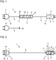
- the charging cable 1 comprises a first connection element 2, which is designed for connection to an energy source external to the vehicle.
- the energy source external to the vehicle can be a charging station, a wall box or an AC network socket.
- the charging cable 1 further comprises a second connection element 3, which is designed for connection to a charging socket of a motor vehicle comprising an electrical traction energy store.
- the second connection element 3 is designed such that it can be connected to a charging socket of the motor vehicle designed for DC charging, for example or to a section of a charging socket of the motor vehicle designed for DC charging.
- the second connection element can be designed, for example, as a CHAdeMO connector or as a CCS connector.
- the charging cable 1 comprises a rectifier 5, which is arranged either in a receiving section 6 of the charging cable 1 having a housing 25 or in the interior of a housing 7 of the second connection element 3.
- the rectifier 5 serves to rectify an alternating current or an alternating voltage fed into the charging cable 1 via the first connecting element 2, so that a traction energy store of a motor vehicle connected to the second connecting element 3 can be charged via the generated direct current or the generated direct voltage.
- the receiving section 6 is connected to the first connection element 2 and the second connection element 3 via a cable section 8.
- the cable sections each comprise a plurality of conductors or wires, which are surrounded by a common, insulating sheath. The number of wires can depend on the design of the first connection element 2 and / or thereafter whether direct current or single-phase or multi-phase alternating current is transmitted via the respective cable section 8.
- the receiving section 6 further comprises a means 9 for galvanic isolation, for example a transformer or a DC converter, and a safety circuit 10 which can interrupt the electrical connection between the first connection element 2 and the second connection element 3, for example when an excessive current occurs in the charging cable 1 .
- a current limiting circuit and / or an RCD switch or a fuse can be used as the safety circuit.
- the charging cable 1 comprises an interface 11 designed as a coupling comprising two coupling sections 26, via which the first connection element 2 is detachably fastened to the charging cable 1.
- the interface can, as in Fig. 1 is shown, be arranged on the receiving section 6.
- a coupling section 26 is arranged on the receiving section and a coupling section 26 is arranged on the cable section 8 connected to the first connection element 2.
- the interface 11 can also be at the position indicated by the line 12 at the first connection element 2 may be arranged.
- a coupling section 26 is arranged on the first connection element 2 and a coupling section 26 on the cable section 8.
- the interface 11 is alternatively arranged at the position on the second connection element 3 identified by the line 13, a coupling section 26 being arranged on the second connection element 3 and a coupling section 26 on the cable section 8.
- first connection elements 2 can be releasably connected to the charging cable 1 via the interface 11. This enables the charging cable 1 to be connected to various types of AC power sources or AC networks.
- a connection to a two-phase or three-phase AC power source can be made, for example, via a first connection element 2 designed as a CEE plug.
- a connection can be made to a single-phase AC power source with a further first connection element 27, for example designed as a protective contact plug.
- the further first connection element 27 is connected to a coupling section 26 via a cable section 8 and, instead of the first connection element 2, can be connected to the charging cable 1 via the interface 11, so that the charging cable 1 for charging via a single-phase connection with the further connection element 27 connectable AC power source can be used.
- a second embodiment of a charging cable 1 is shown.
- the rectifier 5 is arranged in the interior of the housing 7 of the second connection element 3.
- the means for electrical isolation 9 and the electrical safety circuit 10 are arranged in the housing 7 of the second connection element 3.
- the interface 11 is arranged at the position marked with the line 13 on the second connection element.
- an arrangement of the interface 11 at the position marked with the line 12 on the first connection element 2 is possible.
- the detachable connection of the first connection element 2 or the first connection element 2 and the cable section 8 makes it possible to connect different first connection elements 2 to the second connection element 3 or to the cable section 8 and the second connection element 3. This makes it possible to select a suitable first connection element depending on an available charging option and to detachably attach it to the charging cable via the interface 11.
- the first connection element 2 furthermore comprises a resistor 14 as resistance coding.
- the resistance value of the resistor 14 can be read out, for example, by a control device of the rectifier 5 via at least one signal line of the cable section 8, the rectifier 5 being able to be operated as a function of this resistance value.
- This makes it possible, for example when using a first connection element 2, which is designed for connection to a single-phase AC network, to operate in accordance with a single-phase rectification.
- the first connection element 2 can be designed, for example, as a protective contact plug, a specific resistance value of the resistor 14 being assigned to this embodiment.
- connection element 2 can also be encoded via other resistance values of the resistor 14, which enable, for example, a connection to two-phase or three-phase AC networks.
- the rectifier 5 can be operated to rectify a two-phase or three-phase alternating current.
- a temperature sensor 15 is arranged in the first connection element 2 and a temperature sensor 31 is arranged in the second connection element 3, the rectifier being operable as a function of at least one temperature measured by one of the temperature sensors 15, 31. For example, it is possible that when a temperature measured value is exceeded by a temperature value measured by one of the temperature sensors 15, 31, a current flowing through the charging cable 1 is reduced and / or switched off by activating the rectifier 5, so that a Damage or wear of the charging cable 1, in particular the first connection element 2 and / or the second connection element 3, can be avoided.
- the rectifier 5 comprises a current measuring means 16 and a voltage measuring means 17, which are used to measure a current flowing through the charging cable 1 or to measure at least one voltage value of the alternating current and / or the direct current. If the voltage or current is too high, the operation of the rectifier 5 can be adjusted and / or the rectifier 5 can be switched off.
- a schematic circuit diagram of a third exemplary embodiment of a charging cable 1 is shown, which is used for connecting to a single-phase AC power source.
- the rectifier 5 integrated in the housing 7 of the second connection element 3 comprises a control device 18 designed as a microcontroller, which is connected to a rectifier unit 19.
- the rectifier unit 19 serves to rectify a single-phase AC voltage, which is transmitted from the first connection element 2 via the cable section 8 to the second connection element 3.
- the cable section 8 has a first line 26 for the neutral conductor (N), a second line 27 for the phase of the alternating current (L1) and a third line 28 for the protective conductor (PE).
- N neutral conductor
- L1 phase of the alternating current
- PE protective conductor
- the alternating current transmitted from the first connection element 2 to the rectifier 5 is converted into a direct current by the rectifier unit 19 of the rectifier 5.
- the rectifier unit 19 is connected with its DC voltage side to two of the contacts 20 (DC + and DC-) of the second connection element 3 provided for connecting the charging cable 1 to the charging socket of a motor vehicle.
- the rectifier unit 19 comprises semiconductor components made of silicon carbide and / or gallium nitride.
- the rectifier 5 further comprises a circuit 21 for measuring the residual current and a circuit 22 which serves to supply power to the control device 18.
- the resistor 14 provided in the first connection element 2 for resistance coding of the type of the first connection element 2 and the temperature sensor 15 provided in the first connection element 2 are each likewise connected to the control device 18 via a signal line 29 of the cable section 18 via the interface 11.
- a ground line 30 (GND) and two further signal lines 23, 24 (CP_in and PRX) are also provided.
- the signal line 23 can be used for communication between the control device 18 and a charging station connected to the first connection element 2. For example, charging information can be transmitted between the control device 18 and the charging station, as is provided in international standards.
- the signal line 24 can be used, for example, to obtain information regarding a maximum permissible current strength for the first connection element 2 or the cable section 8 via a resistance coding.
- the control device 18 is connected to contacts (CP_out, PRX_out) of the contacts 20 provided for signal transmission.
- a temperature of the second connection element 3 can be measured by the control device 18 via a temperature sensor 31. If the measured temperature of the second connection element 3 is too high or the temperature of the first connection element 2 measured via the temperature sensor 15 is too high, the current transmitted via the charging cable 1 can be reduced and / or switched off by actuating the rectifier unit 19. To avoid excessive currents, the rectifier 5 further comprises three fuses F1, F2 and F3.
- the rectifier 5 can be activated by the control device 18 by controlling the rectifier unit 19 operate.
- a possibly existing second phase and / or a possibly existing third phase of an alternating current source can in each case be connected to the alternating current side of the rectifier unit 19 via additional contacts (not shown) of the interface 11, so that when the first connection element 2 is connected to a charging station which has a two-phase connection or provides a three-phase alternating current, all phases of the alternating current can be rectified.
Landscapes
- Engineering & Computer Science (AREA)
- Power Engineering (AREA)
- Transportation (AREA)
- Mechanical Engineering (AREA)
- Microelectronics & Electronic Packaging (AREA)
- Electric Propulsion And Braking For Vehicles (AREA)
- Charge And Discharge Circuits For Batteries Or The Like (AREA)
Applications Claiming Priority (1)
| Application Number | Priority Date | Filing Date | Title |
|---|---|---|---|
| DE102019200870.4A DE102019200870A1 (de) | 2019-01-24 | 2019-01-24 | Ladekabel |
Publications (1)
| Publication Number | Publication Date |
|---|---|
| EP3686047A1 true EP3686047A1 (fr) | 2020-07-29 |
Family
ID=68886765
Family Applications (1)
| Application Number | Title | Priority Date | Filing Date |
|---|---|---|---|
| EP19215153.8A Ceased EP3686047A1 (fr) | 2019-01-24 | 2019-12-11 | Câble de charge |
Country Status (4)
| Country | Link |
|---|---|
| US (1) | US11285830B2 (fr) |
| EP (1) | EP3686047A1 (fr) |
| CN (1) | CN111469684A (fr) |
| DE (1) | DE102019200870A1 (fr) |
Cited By (1)
| Publication number | Priority date | Publication date | Assignee | Title |
|---|---|---|---|---|
| DE102022121713A1 (de) | 2022-08-26 | 2024-02-29 | Compleo Charging Solutions Ag | Betriebsverfahren für eine Versorgungsstation und Verwendung eines Temperatursensors als Diebstahlindikator |
Families Citing this family (19)
| Publication number | Priority date | Publication date | Assignee | Title |
|---|---|---|---|---|
| US11594847B2 (en) * | 2020-04-30 | 2023-02-28 | Kevin O'Rourke | Wireless monitoring of electrical connector |
| EP4136715A1 (fr) * | 2020-05-01 | 2023-02-22 | Eaton Intelligent Power Limited | Système de câble et de connecteurs à capteurs intégrés |
| KR102767529B1 (ko) * | 2020-07-24 | 2025-02-13 | 현대자동차주식회사 | 전기자동차용 인케이블컨트롤박스의 진단시스템 및 그 방법 |
| CN112072412B (zh) * | 2020-09-09 | 2022-07-26 | 菲尼克斯(南京)新能源汽车技术有限公司 | 带过温保护的插头组件 |
| US11603005B2 (en) * | 2020-09-30 | 2023-03-14 | GM Global Technology Operations LLC | Apparatus and method of quick charging an electric vehicle |
| US12062869B2 (en) | 2020-12-18 | 2024-08-13 | Webasto Charging Systems, Inc. | Electrical connector assembly |
| CN112909667A (zh) * | 2021-03-03 | 2021-06-04 | 蔚来汽车科技(安徽)有限公司 | 充电枪 |
| DE102021112750A1 (de) | 2021-05-17 | 2022-11-17 | Webasto SE | Ladekabel, Ladestation Ladesystem und Verfahren zum Laden einer Traktionsbatterie eines Elektrofahrzeuges |
| WO2022245727A1 (fr) * | 2021-05-17 | 2022-11-24 | Power Hero Corp. | Commande sans fil et locale d'un flux bidirectionnel d'électricité entre un ev et des équipements d'alimentation ev et entre un ou plusieurs evse et un réseau |
| DE102021206601B4 (de) | 2021-06-25 | 2023-03-02 | Robert Bosch Gesellschaft mit beschränkter Haftung | Elektrisches Versorgungskabel für ein Fahrzeug |
| DE102021206603A1 (de) | 2021-06-25 | 2022-12-29 | Robert Bosch Gesellschaft mit beschränkter Haftung | Verbinder eines elektrischen Versorgungskabels für ein Fahrzeug |
| KR20230063796A (ko) * | 2021-11-02 | 2023-05-09 | 현대자동차주식회사 | 충전장비간 체결오류 검출 장치 및 검출 방법 |
| EP4186742A1 (fr) * | 2021-11-25 | 2023-05-31 | ABB E-mobility B.V. | Connecteur de recharge de véhicule électrique à inertie thermique et procédé |
| CN115117700A (zh) * | 2022-06-27 | 2022-09-27 | 李启源 | 一种智能可更换配置的新能源汽车充电线及其工作方法 |
| PL442308A1 (pl) * | 2022-09-16 | 2024-03-18 | Csg Spółka Akcyjna | Przewód do ładowania, zwłaszcza do pojazdów elektrycznych oraz sposób komunikacji i produkt komputerowy |
| DE102022210622A1 (de) * | 2022-10-07 | 2024-04-18 | Volkswagen Aktiengesellschaft | Verbindungsmodul, System und Kraftfahrzeug |
| DE102023201215A1 (de) * | 2023-02-14 | 2024-08-14 | Vitesco Technologies GmbH | Ladevorrichtung mit einer Datenschnittstelle zum Ausgeben von Ladedaten einer Fahrzeugbatterie |
| US20240308375A1 (en) * | 2023-03-14 | 2024-09-19 | Ford Global Technologies, Llc | Vehicle charging systems and methods for mitigating electric vehicle supply equipment overheating |
| CN116176318B (zh) * | 2023-04-26 | 2023-07-14 | 威驰腾(福建)汽车有限公司 | 一种车辆对车辆充电装置 |
Citations (11)
| Publication number | Priority date | Publication date | Assignee | Title |
|---|---|---|---|---|
| JP2009194958A (ja) * | 2008-02-12 | 2009-08-27 | Kansai Electric Power Co Inc:The | 充電制御装置及び充電システム |
| DE102010053074A1 (de) * | 2010-12-01 | 2011-08-25 | Daimler AG, 70327 | Ladekabelvorrichtung sowie Verfahren zum Begrenzen eines maximalen elektrischen Stroms |
| DE102011107628A1 (de) * | 2011-06-30 | 2013-01-03 | Rwe Ag | Ladevorrichtung für elektrofahrzeuge und verfahren zum laden von elektrofahrzeugen |
| DE102013007330A1 (de) * | 2013-04-27 | 2014-10-30 | Volkswagen Aktiengesellschaft | Wechselstecker zum länderübergreifenden elektrischen Laden eines Fortbewegungsmittels |
| FR3013165A1 (fr) * | 2013-11-08 | 2015-05-15 | Intelligent Electronic Systems | Dispositif de charge compact pour vehicule electrique |
| DE102015207400A1 (de) | 2014-05-12 | 2015-11-12 | Heidelberger Druckmaschinen Ag Intellectual Property | Kabelaufwickelvorrichtung mit Übertrager |
| DE102016106840A1 (de) | 2016-04-13 | 2017-10-19 | Tim Munstermann | Energieübertragungsvorrichtung, Energieübertragungssystem, Elektrofahrzeug-Ladestation und Elektrofahrzeug-Ladeverfahren |
| US20170320397A1 (en) * | 2014-11-13 | 2017-11-09 | Audi Ag | Motor vehicle charging socket having overheating protection |
| DE202017102886U1 (de) * | 2017-05-15 | 2018-08-20 | Phoenix Contact E-Mobility Gmbh | Adapterstecker für ein Ladesystem zum Aufladen eines Elektrofahrzeugs |
| US20180361862A1 (en) * | 2016-02-11 | 2018-12-20 | Lear Corporation | Vehicle charge-cord system |
| DE112016006739T5 (de) * | 2016-04-13 | 2019-01-03 | Mitsubishi Electric Corporation | Ladevorrichtung/Entladevorrichtung |
Family Cites Families (6)
| Publication number | Priority date | Publication date | Assignee | Title |
|---|---|---|---|---|
| DE102011084527A1 (de) | 2011-10-14 | 2013-04-18 | Siemens Aktiengesellschaft | Ladeinfrastruktur für Elektrofahrzeuge |
| EP2612786B1 (fr) * | 2012-01-09 | 2018-12-12 | Tata Technologies Pte Ltd | Chargement de pairage pour véhicules électriques |
| JP5672356B2 (ja) * | 2012-12-21 | 2015-02-18 | 株式会社デンソー | 充電ケーブル装置 |
| DE202016103030U1 (de) | 2016-06-07 | 2017-09-09 | Müller Plastik GmbH | Stecker, insbesondere mit einem Fahrzeugladekabel eines Elektro- oder Hybridfahrzeuges |
| EP3266646A1 (fr) | 2016-07-01 | 2018-01-10 | Hyundai Motor Company | Boîte de commande du câble d'entrée monté sur un câble de charge de véhicule électrique et procédé de charge de véhicule électrique faisant appel à celui-ci |
| CN207403594U (zh) * | 2017-11-13 | 2018-05-25 | 重庆国翰能源发展有限公司 | 一种带充电指示的新型充电枪 |
-
2019
- 2019-01-24 DE DE102019200870.4A patent/DE102019200870A1/de not_active Ceased
- 2019-12-11 EP EP19215153.8A patent/EP3686047A1/fr not_active Ceased
-
2020
- 2020-01-03 US US16/733,668 patent/US11285830B2/en active Active
- 2020-01-22 CN CN202010075081.7A patent/CN111469684A/zh active Pending
Patent Citations (11)
| Publication number | Priority date | Publication date | Assignee | Title |
|---|---|---|---|---|
| JP2009194958A (ja) * | 2008-02-12 | 2009-08-27 | Kansai Electric Power Co Inc:The | 充電制御装置及び充電システム |
| DE102010053074A1 (de) * | 2010-12-01 | 2011-08-25 | Daimler AG, 70327 | Ladekabelvorrichtung sowie Verfahren zum Begrenzen eines maximalen elektrischen Stroms |
| DE102011107628A1 (de) * | 2011-06-30 | 2013-01-03 | Rwe Ag | Ladevorrichtung für elektrofahrzeuge und verfahren zum laden von elektrofahrzeugen |
| DE102013007330A1 (de) * | 2013-04-27 | 2014-10-30 | Volkswagen Aktiengesellschaft | Wechselstecker zum länderübergreifenden elektrischen Laden eines Fortbewegungsmittels |
| FR3013165A1 (fr) * | 2013-11-08 | 2015-05-15 | Intelligent Electronic Systems | Dispositif de charge compact pour vehicule electrique |
| DE102015207400A1 (de) | 2014-05-12 | 2015-11-12 | Heidelberger Druckmaschinen Ag Intellectual Property | Kabelaufwickelvorrichtung mit Übertrager |
| US20170320397A1 (en) * | 2014-11-13 | 2017-11-09 | Audi Ag | Motor vehicle charging socket having overheating protection |
| US20180361862A1 (en) * | 2016-02-11 | 2018-12-20 | Lear Corporation | Vehicle charge-cord system |
| DE102016106840A1 (de) | 2016-04-13 | 2017-10-19 | Tim Munstermann | Energieübertragungsvorrichtung, Energieübertragungssystem, Elektrofahrzeug-Ladestation und Elektrofahrzeug-Ladeverfahren |
| DE112016006739T5 (de) * | 2016-04-13 | 2019-01-03 | Mitsubishi Electric Corporation | Ladevorrichtung/Entladevorrichtung |
| DE202017102886U1 (de) * | 2017-05-15 | 2018-08-20 | Phoenix Contact E-Mobility Gmbh | Adapterstecker für ein Ladesystem zum Aufladen eines Elektrofahrzeugs |
Non-Patent Citations (2)
| Title |
|---|
| ANONYMOUS: "Gallium nitride - Wikipedia", 21 January 2019 (2019-01-21), XP055878394, Retrieved from the Internet <URL:https://en.wikipedia.org/w/index.php?title=Gallium_nitride&oldid=879521224> [retrieved on 20220112] * |
| ANONYMOUS: "Siliciumcarbid - Wikipedia", 19 December 2018 (2018-12-19), XP055878397, Retrieved from the Internet <URL:https://de.wikipedia.org/w/index.php?title=Siliciumcarbid&oldid=183861164#Halbleitermaterial> [retrieved on 20220112] * |
Cited By (2)
| Publication number | Priority date | Publication date | Assignee | Title |
|---|---|---|---|---|
| DE102022121713A1 (de) | 2022-08-26 | 2024-02-29 | Compleo Charging Solutions Ag | Betriebsverfahren für eine Versorgungsstation und Verwendung eines Temperatursensors als Diebstahlindikator |
| EP4331890A1 (fr) | 2022-08-26 | 2024-03-06 | Compleo Charging Solutions GmbH & Co. KG | Procédé de fonctionnement d'une station d'alimentation et utilisation d'un capteur de température en tant qu'indicateur de vol |
Also Published As
| Publication number | Publication date |
|---|---|
| US11285830B2 (en) | 2022-03-29 |
| CN111469684A (zh) | 2020-07-31 |
| US20200238841A1 (en) | 2020-07-30 |
| DE102019200870A1 (de) | 2020-07-30 |
Similar Documents
| Publication | Publication Date | Title |
|---|---|---|
| EP3686047A1 (fr) | Câble de charge | |
| DE102013007330B4 (de) | Teilesatz mit Wechselstecker zum länderübergreifenden elektrischen Laden eines Fortbewegungsmittels | |
| DE102010028626B4 (de) | Stromaufladevorrichtung für ein Elektrofahrzeug | |
| WO2012143254A2 (fr) | Dispositif de charge pour véhicule | |
| KR102327843B1 (ko) | 전기 자동차들을 충전하기 위한 전력 공급 시스템 | |
| DE102016214050B4 (de) | Anordnung aus einem Kraftfahrzeug und einem Verbindungsmittel, Kraftfahrzeug und Verbindungsmittel | |
| EP1988612A2 (fr) | Dispositif de refroidissement mobile fonctionnant à l'aide d'un courant continu à basse tension | |
| EP3192139B1 (fr) | Procédé et dispositif de détection d'un courant de court-circuit continu | |
| DE102021125345A1 (de) | Kopplungsvorrichtung für ein Elektrofahrzeug | |
| WO2014140004A2 (fr) | Dispositif de charge pour véhicule électrique | |
| DE102015225856B4 (de) | Ladevorrichtung und Ladeverfahren für eine Hochvoltbatterie eines Kraftfahrzeugs | |
| WO2011054849A2 (fr) | Système de charge pour véhicules électriques | |
| DE102012202130A1 (de) | Elektrisches Stromversorgungssystem | |
| DE102022202826A1 (de) | Verbinder für ein Versorgungskabel | |
| DE102019132027A1 (de) | Portables Steckernetzteil zum temporären Verbinden eines elektrisch antreibbaren Kraftfahrzeugs mit einem stationären Stromnetz sowie Betriebsverfahren für das Steckernetzteil | |
| EP3435512A1 (fr) | Station de charge à surveillance de courant différentiel destinée à charger un accumulateur d'énergie électrique d'un véhicule électrique | |
| DE102015200960B4 (de) | Ladevorrichtung und Ladesystem | |
| DE102018219296A1 (de) | Vorrichtung zum Laden einer Batterie eines elektrisch angetriebenen Kraftfahrzeugs | |
| DE102011101530B4 (de) | Verfahren für eine Ladevorrichtung eines Fahrzeugs | |
| EP3533658B1 (fr) | Station de chargement et système de chargement pour vehicule électriques | |
| WO2019219647A1 (fr) | Procédé destiné à faire fonctionner un dispositif de charge et dispositif de charge destiné à charger un accumulateur d'énergie pour véhicules électriques | |
| DE102021214174B4 (de) | Vorrichtung und verfahren zum steuern der ladeleistung beim laden einer zu ladenden vorrichtung unter verwendung eines intelligenten ladekabels | |
| DE102020104736A1 (de) | Kraftfahrzeug umfassend eine Ladeeinrichtung | |
| DE102019200871B4 (de) | Ladekabel und Kraftfahrzeug | |
| DE102017214024A1 (de) | Wechselspannungsadapter für ein Kraftfahrzeug |
Legal Events
| Date | Code | Title | Description |
|---|---|---|---|
| PUAI | Public reference made under article 153(3) epc to a published international application that has entered the european phase |
Free format text: ORIGINAL CODE: 0009012 |
|
| STAA | Information on the status of an ep patent application or granted ep patent |
Free format text: STATUS: THE APPLICATION HAS BEEN PUBLISHED |
|
| AK | Designated contracting states |
Kind code of ref document: A1 Designated state(s): AL AT BE BG CH CY CZ DE DK EE ES FI FR GB GR HR HU IE IS IT LI LT LU LV MC MK MT NL NO PL PT RO RS SE SI SK SM TR |
|
| AX | Request for extension of the european patent |
Extension state: BA ME |
|
| STAA | Information on the status of an ep patent application or granted ep patent |
Free format text: STATUS: REQUEST FOR EXAMINATION WAS MADE |
|
| 17P | Request for examination filed |
Effective date: 20210129 |
|
| RBV | Designated contracting states (corrected) |
Designated state(s): AL AT BE BG CH CY CZ DE DK EE ES FI FR GB GR HR HU IE IS IT LI LT LU LV MC MK MT NL NO PL PT RO RS SE SI SK SM TR |
|
| STAA | Information on the status of an ep patent application or granted ep patent |
Free format text: STATUS: EXAMINATION IS IN PROGRESS |
|
| 17Q | First examination report despatched |
Effective date: 20210324 |
|
| P01 | Opt-out of the competence of the unified patent court (upc) registered |
Effective date: 20230529 |
|
| STAA | Information on the status of an ep patent application or granted ep patent |
Free format text: STATUS: THE APPLICATION HAS BEEN REFUSED |
|
| 18R | Application refused |
Effective date: 20240115 |