EP3686062B1 - Dispositif pour véhicule automobile - Google Patents
Dispositif pour véhicule automobile Download PDFInfo
- Publication number
- EP3686062B1 EP3686062B1 EP20153181.1A EP20153181A EP3686062B1 EP 3686062 B1 EP3686062 B1 EP 3686062B1 EP 20153181 A EP20153181 A EP 20153181A EP 3686062 B1 EP3686062 B1 EP 3686062B1
- Authority
- EP
- European Patent Office
- Prior art keywords
- detection unit
- environment detection
- protective element
- cam
- accordance
- Prior art date
- Legal status (The legal status is an assumption and is not a legal conclusion. Google has not performed a legal analysis and makes no representation as to the accuracy of the status listed.)
- Active
Links
Images


Classifications
-
- B—PERFORMING OPERATIONS; TRANSPORTING
- B60—VEHICLES IN GENERAL
- B60R—VEHICLES, VEHICLE FITTINGS, OR VEHICLE PARTS, NOT OTHERWISE PROVIDED FOR
- B60R11/00—Arrangements for holding or mounting articles, not otherwise provided for
- B60R11/04—Mounting of cameras operative during drive; Arrangement of controls thereof relative to the vehicle
-
- G—PHYSICS
- G01—MEASURING; TESTING
- G01B—MEASURING LENGTH, THICKNESS OR SIMILAR LINEAR DIMENSIONS; MEASURING ANGLES; MEASURING AREAS; MEASURING IRREGULARITIES OF SURFACES OR CONTOURS
- G01B5/00—Measuring arrangements characterised by the use of mechanical techniques
- G01B5/0002—Arrangements for supporting, fixing or guiding the measuring instrument or the object to be measured
-
- G—PHYSICS
- G01—MEASURING; TESTING
- G01D—MEASURING NOT SPECIALLY ADAPTED FOR A SPECIFIC VARIABLE; ARRANGEMENTS FOR MEASURING TWO OR MORE VARIABLES NOT COVERED IN A SINGLE OTHER SUBCLASS; TARIFF METERING APPARATUS; MEASURING OR TESTING NOT OTHERWISE PROVIDED FOR
- G01D11/00—Component parts of measuring arrangements not specially adapted for a specific variable
- G01D11/20—Caging devices for moving parts when not in use
-
- G—PHYSICS
- G01—MEASURING; TESTING
- G01D—MEASURING NOT SPECIALLY ADAPTED FOR A SPECIFIC VARIABLE; ARRANGEMENTS FOR MEASURING TWO OR MORE VARIABLES NOT COVERED IN A SINGLE OTHER SUBCLASS; TARIFF METERING APPARATUS; MEASURING OR TESTING NOT OTHERWISE PROVIDED FOR
- G01D11/00—Component parts of measuring arrangements not specially adapted for a specific variable
- G01D11/24—Housings ; Casings for instruments
- G01D11/245—Housings for sensors
-
- G—PHYSICS
- G01—MEASURING; TESTING
- G01D—MEASURING NOT SPECIALLY ADAPTED FOR A SPECIFIC VARIABLE; ARRANGEMENTS FOR MEASURING TWO OR MORE VARIABLES NOT COVERED IN A SINGLE OTHER SUBCLASS; TARIFF METERING APPARATUS; MEASURING OR TESTING NOT OTHERWISE PROVIDED FOR
- G01D11/00—Component parts of measuring arrangements not specially adapted for a specific variable
- G01D11/30—Supports specially adapted for an instrument; Supports specially adapted for a set of instruments
-
- G—PHYSICS
- G01—MEASURING; TESTING
- G01N—INVESTIGATING OR ANALYSING MATERIALS BY DETERMINING THEIR CHEMICAL OR PHYSICAL PROPERTIES
- G01N29/00—Investigating or analysing materials by the use of ultrasonic, sonic or infrasonic waves; Visualisation of the interior of objects by transmitting ultrasonic or sonic waves through the object
- G01N29/22—Details, e.g. general constructional or apparatus details
- G01N29/26—Arrangements for orientation or scanning by relative movement of the head and the sensor
- G01N29/265—Arrangements for orientation or scanning by relative movement of the head and the sensor by moving the sensor relative to a stationary material
-
- G—PHYSICS
- G21—NUCLEAR PHYSICS; NUCLEAR ENGINEERING
- G21C—NUCLEAR REACTORS
- G21C17/00—Monitoring; Testing ; Maintaining
- G21C17/017—Inspection or maintenance of pipe-lines or tubes in nuclear installations
-
- H—ELECTRICITY
- H04—ELECTRIC COMMUNICATION TECHNIQUE
- H04N—PICTORIAL COMMUNICATION, e.g. TELEVISION
- H04N23/00—Cameras or camera modules comprising electronic image sensors; Control thereof
- H04N23/50—Constructional details
- H04N23/51—Housings
-
- H—ELECTRICITY
- H04—ELECTRIC COMMUNICATION TECHNIQUE
- H04N—PICTORIAL COMMUNICATION, e.g. TELEVISION
- H04N23/00—Cameras or camera modules comprising electronic image sensors; Control thereof
- H04N23/50—Constructional details
- H04N23/54—Mounting of pick-up tubes, electronic image sensors, deviation or focusing coils
-
- B—PERFORMING OPERATIONS; TRANSPORTING
- B60—VEHICLES IN GENERAL
- B60R—VEHICLES, VEHICLE FITTINGS, OR VEHICLE PARTS, NOT OTHERWISE PROVIDED FOR
- B60R11/00—Arrangements for holding or mounting articles, not otherwise provided for
- B60R2011/0042—Arrangements for holding or mounting articles, not otherwise provided for characterised by mounting means
- B60R2011/008—Adjustable or movable supports
- B60R2011/0082—Adjustable or movable supports collapsible, e.g. for storing after use
-
- B—PERFORMING OPERATIONS; TRANSPORTING
- B60—VEHICLES IN GENERAL
- B60R—VEHICLES, VEHICLE FITTINGS, OR VEHICLE PARTS, NOT OTHERWISE PROVIDED FOR
- B60R11/00—Arrangements for holding or mounting articles, not otherwise provided for
- B60R2011/0042—Arrangements for holding or mounting articles, not otherwise provided for characterised by mounting means
- B60R2011/008—Adjustable or movable supports
- B60R2011/0085—Adjustable or movable supports with adjustment by rotation in their operational position
- B60R2011/0089—Adjustable or movable supports with adjustment by rotation in their operational position around three axes, i.e. universally mounted
-
- B—PERFORMING OPERATIONS; TRANSPORTING
- B60—VEHICLES IN GENERAL
- B60R—VEHICLES, VEHICLE FITTINGS, OR VEHICLE PARTS, NOT OTHERWISE PROVIDED FOR
- B60R11/00—Arrangements for holding or mounting articles, not otherwise provided for
- B60R2011/0042—Arrangements for holding or mounting articles, not otherwise provided for characterised by mounting means
- B60R2011/008—Adjustable or movable supports
- B60R2011/0092—Adjustable or movable supports with motorization
-
- B—PERFORMING OPERATIONS; TRANSPORTING
- B60—VEHICLES IN GENERAL
- B60R—VEHICLES, VEHICLE FITTINGS, OR VEHICLE PARTS, NOT OTHERWISE PROVIDED FOR
- B60R11/00—Arrangements for holding or mounting articles, not otherwise provided for
- B60R2011/0094—Arrangements for holding or mounting articles, not otherwise provided for characterised by means for covering after user, e.g. boxes, shutters or the like
-
- G—PHYSICS
- G01—MEASURING; TESTING
- G01S—RADIO DIRECTION-FINDING; RADIO NAVIGATION; DETERMINING DISTANCE OR VELOCITY BY USE OF RADIO WAVES; LOCATING OR PRESENCE-DETECTING BY USE OF THE REFLECTION OR RERADIATION OF RADIO WAVES; ANALOGOUS ARRANGEMENTS USING OTHER WAVES
- G01S13/00—Systems using the reflection or reradiation of radio waves, e.g. radar systems; Analogous systems using reflection or reradiation of waves whose nature or wavelength is irrelevant or unspecified
- G01S13/88—Radar or analogous systems specially adapted for specific applications
- G01S13/93—Radar or analogous systems specially adapted for specific applications for anti-collision purposes
- G01S13/931—Radar or analogous systems specially adapted for specific applications for anti-collision purposes of land vehicles
- G01S2013/9323—Alternative operation using light waves
-
- G—PHYSICS
- G01—MEASURING; TESTING
- G01S—RADIO DIRECTION-FINDING; RADIO NAVIGATION; DETERMINING DISTANCE OR VELOCITY BY USE OF RADIO WAVES; LOCATING OR PRESENCE-DETECTING BY USE OF THE REFLECTION OR RERADIATION OF RADIO WAVES; ANALOGOUS ARRANGEMENTS USING OTHER WAVES
- G01S7/00—Details of systems according to groups G01S13/00, G01S15/00, G01S17/00
- G01S7/02—Details of systems according to groups G01S13/00, G01S15/00, G01S17/00 of systems according to group G01S13/00
- G01S7/027—Constructional details of housings, e.g. form, type, material or ruggedness
-
- Y—GENERAL TAGGING OF NEW TECHNOLOGICAL DEVELOPMENTS; GENERAL TAGGING OF CROSS-SECTIONAL TECHNOLOGIES SPANNING OVER SEVERAL SECTIONS OF THE IPC; TECHNICAL SUBJECTS COVERED BY FORMER USPC CROSS-REFERENCE ART COLLECTIONS [XRACs] AND DIGESTS
- Y02—TECHNOLOGIES OR APPLICATIONS FOR MITIGATION OR ADAPTATION AGAINST CLIMATE CHANGE
- Y02E—REDUCTION OF GREENHOUSE GAS [GHG] EMISSIONS, RELATED TO ENERGY GENERATION, TRANSMISSION OR DISTRIBUTION
- Y02E30/00—Energy generation of nuclear origin
- Y02E30/30—Nuclear fission reactors
Definitions
- the present invention relates to a device for a motor vehicle with a protective element, which can be pivoted from a closed position into an open position, with an environment detection unit, which can be brought into an active position for image detection by an extension movement and into a rest position by means of a retraction movement, in which the environment detection unit is arranged inaccessible from the outside behind the protective element located in the closed position, and with a drive unit engaging the environment detection unit for moving the environment detection unit, the environment detection unit having an end face facing the protective element and two adjoining side surfaces.
- the protective element is held in the closed position by a spring element and pressed on over the end face of the extending environment detection unit.
- the problem with these devices is that the environment detection unit cannot be permanently and reliably protected from external influences such as dust and / or moisture in its rest position.
- a device is also known in which the environment detection unit and the protective element are connected to one another in an articulated manner, that is to say are permanently in engagement with one another.
- the driven environment detection unit not only pushes the protective element open into the open position, but also pulls the protective element back into the closed position.
- a pivot axis of the environment detection unit, a swivel axis of the protective element and a hinge axis of the connecting joint between the environment detection unit and protective element have to be precisely aligned with one another for trouble-free and low-noise operation of the device, which is not always due to tolerances in practice will be the case.
- a camera holder is provided with a guide groove in which a pin formed on a protective flap engages.
- the protective flap is carried along by the pin and pivoted between an active position and a rest position.
- the DE 10 2017 105 964 A1 discloses an extendable environment detection unit which presses open a camera cover by means of a projection attached to the front when it is extended into an active position.
- a spring element acts on the camera cover to push it into a rest position.
- a pin formed on the camera cover is detected by a driver element formed on the environment detection unit and the camera cover is pulled into its closed position.
- the invention is based on the object of creating a device of the type mentioned at the outset which not only reliably protects the environment detection unit in its rest position from external influences in the long term, but also permanently ensures perfect mechanical function.
- the invention is based on the general idea of not connecting the environment detection unit permanently and in particular not in an articulated manner to the protective element, but instead providing separate pressing and closing elements for moving the protective element on the environment detection unit.
- an additional degree of freedom is created, which means that the device is less sensitive to tolerances, in particular in the alignment of a pivot axis of the protective element relative to an axis of rotation of the environment detection unit.
- This not only ensures a permanently reliable mechanical function of the device, but also minimizes the development of noise during operation of the device, in particular during the extension and retraction movement of the environment detection unit.
- shifting the pressing element and closing element to the side surface of the environment detection unit in other words by arranging the pressing element and closing element on the side, the distance between the environment detection unit and the protective element can be minimized and thus a more compact design of the device can be achieved.
- the environment detection unit can include, for example, a camera, a LiDAR, LaDAR or radar device or some other optical sensor which is suitable for detecting the vehicle environment. Furthermore, it is conceivable that the environment detection unit is arranged behind the emblem of a vehicle manufacturer.
- the protective element can in principle be formed by the emblem itself. However, the protective element is preferably designed in the form of a separate camera cover, which is optionally arranged between the emblem and the environment detection unit.
- the push-on element forms a lateral rib through which the protective element can be pivoted into the open position during the extension of the environment detection unit via a first cam of the protective element supported on the rib.
- the closing element is preferably effective temporarily; in particular, it can only become effective during an end phase of the retraction movement of the environment detection unit, ie when the approaching environment detection unit is moving approaches their rest position.
- the closing element and the protective element only come into engagement shortly before reaching the rest position, namely exclusively in order to finally pull the protective element into the closed position, while the closing element and the protective element are disengaged during the predominant part of the retraction movement of the environment detection unit.
- the closing element can be formed by a lateral projection.
- a securing element for securing the protective element on the environment capturing unit located in the active position is formed on the side surface of the environment detection unit.
- the securing element is preferably arranged separately from the pressing element and the closing element.
- it can be formed by a lateral projection of the environment detection unit.
- the securing element is advantageously temporarily effective, in particular it can only become effective during an end phase of the extension movement of the environment detection unit, i.e. when the extension environment detection unit approaches its active position.
- the securing element and the protective element only come into engagement shortly before the active position is reached, while the securing element and the protective element are disengaged during the predominant part of the movement of the environment detection unit.
- the protective element has a second cam which, according to one embodiment, can be grasped from behind by the securing element when the environment detection unit is in the active position, in particular such that the first and the second cams of the protective element are accommodated between the push-on element and the securing element without play.
- the protective element has a second cam which can be grasped from behind by the closing element when the environment detection unit is in the rest position, in such a way that the first and second cams of the protective element are accommodated between the pressing element and the closing element without play.
- This second cam is preferably the second cam which also engages with the securing element.
- a pressing element, a closing element and / or a securing element are / is preferably formed on opposite side surfaces of the environment detection unit.
- the protective element has at least one extension which overlaps with a side surface of the environment detection unit and on which a first cam and / or a second cam are / is formed.
- the protective element advantageously has two extensions which overlap with opposite side surfaces of the environment detection unit and on each of which a first and / or a second cam is / is formed.
- the or each side face of the environment detection unit is preferably oriented essentially at right angles to the protective element.
- the environment detection unit is mounted rotatably about a first and a second axis of rotation. This allows Represent camera movements that go beyond a simple rotation and allow a more compact design of the device as a whole.
- the first axis of rotation can be displaceably guided in a, in particular curved, link and / or the second axis of rotation can be arranged on a swivel arm, which in turn can be swiveled about a third axis of rotation.
- the drive unit comprises a curved toothed rack connected to the environment detection unit, in particular in an articulated manner.
- the curvature of the rack which can be driven, for example, by a drive motor, in particular an electric motor, contributes to a more compact design of the device as a whole.
- a particularly good protection of the environment detection unit in the rest position against external influences is achieved if the protective element is pulled by the environment detection unit in the rest position against a sealing element which is arranged in the area of a housing opening to be closed by the protective element.
- the sealing element advantageously surrounds the housing opening at least approximately completely.
- a spring element can be provided, against the restoring force of which the protective element can be pivoted from the closed position into the open position.
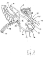
- the device shown in the figures has an environment detection unit 10 which, in the present exemplary embodiment, comprises a reversing camera 12 for a motor vehicle.
- the environment detection unit 10 is mounted rotatably about a first axis of rotation 14 and a second axis of rotation 16 spaced apart therefrom.
- the first axis of rotation 14 is displaceably guided along a curved link, not shown, while the second axis of rotation 16 is arranged at a first end of a pivot arm 18, the second end of which is rotatably mounted about a third axis of rotation 20.
- the environment detection unit 10 is moved into an active position for image detection ( Fig. 3 ) and by moving into a rest position ( Fig. 1 ) bringable.
- the extension and retraction movements of the environment detection unit 10 are brought about by a drive unit which comprises a toothed rack 22 which is connected in an articulated manner to the environment detection unit 10.
- the rack 22 engages the environment detection unit 10 in the area of the first end of the swivel arm 18 in such a way that the second axis of rotation 16 and the joint axis of the rack 22 coincide. Due to the biaxial mounting of the environment detection unit 10 and the curved shape of the rack 22, the environment detection unit 10 performs a combination of rotation and translation during the extension and retraction movements.
- the environment detection unit 10 is accommodated in a housing, not shown in detail, which has a housing wall which delimits a housing opening through which the environment detection unit 10 extends from its rest position into its active position or from its active position in can retract their rest position.
- the housing wall carries a sealing element which at least approximately completely surrounds the housing opening.
- a camera cover 24 is attached to the housing, which is mounted about a fourth axis of rotation 25 and, against the restoring force of a spring element (not shown) between a spring element in FIG Fig. 1 closed position shown and one in Fig. 3 open position shown can be pivoted. In its closed position, the camera cover 24 closes the housing opening in order to protect the environment detection unit 10, which is in the rest position, from external influences. In other words, the camera cover 24 thus forms a protective element.
- two mutually spaced extensions 26 are formed which extend in the direction of the environment detection unit 10 and overlap with opposite side surfaces 28 of the environment detection unit 10. In other words, the extensions 26 accommodate part of the environment detection unit 10 between them.
- each extension 26 In an end region of each extension 26 remote from the camera cover 24, a first cam 30 facing the respective other extension 26 is formed.
- each extension 26 is provided with a second cam 32 which also faces the respective other extension 26.
- the second cam 32 is spaced apart from the first cam 30 of the same extension 26 and is arranged closer to the camera cover 24.
- the surroundings detection unit 10 each has a rib 34 which forms a guide track 36 for one of the first cams 30 in each case.
- the design of the guide tracks 36 and the arrangement of the first cams 30 are adapted to one another in such a way that the first cams 30 are always, ie in every position of the environment detection unit 10 support on the ribs 34. In other words, the camera cover 24 always rests laterally on the surroundings detection unit 10.
- each first cam 30 moves along the guide track 36 assigned to it.
- the second cams 32 come into engagement with first projections 38 which are formed on the side surfaces 28 of the environment detection unit 10 in such a way that the first and second Cams 30, 32 of each extension 26 come to lie between the associated rib 34 and the associated first projection 38.
- the surface of the associated first projection 38 facing the second cam 32 is inclined in such a way that the first and second cams 30, 32 of each extension 26 at the end of the extension movement, ie when the environment detection unit 10 is in its active position, free of play between the associated rib 34 and the associated first projection 38 are received.
- the camera cover 24 is secured against being lifted off from the surroundings detection unit 10 by the first projections 38, i.e. it cannot be opened any further.
- the first projections 38 form securing elements for the camera cover 24.
- the second cams 32 and the first projections 38 disengage again and the The camera cover 24 is only pressed against the environment detection unit 10 by the spring element, ie only the first cams 30 are supported on the ribs 34.
- the second cams 32 When the environment detection unit 10 approaches its rest position, i.e. the retraction movement is in its final phase, the second cams 32 come into engagement with second projections 40, which are formed on the side surfaces 28 of the environment detection unit 10 at a distance from the first projections 38.
- the second cams 32 come into engagement with the second projections 40 in such a way that the first and second cams 30, 32 of each extension 26 come to lie between the associated rib 34 and the associated second projection 40.
- the surface of the associated second projection 38 facing the second cam 32 is arranged at an angle in such a way that the first and second cams 30, 32 of each extension 26 at the end of the retraction movement, ie when the environment detection unit 10 is in its rest position, free of play between the associated rib 34 and the associated second projection 38 are received.
- the camera cover 24 When the environment detection unit 10 is in the rest position, the camera cover 24 is actively pulled by the second projections 40 against the seal surrounding the housing opening, which is why the second projections 40 can also be referred to as closing elements.
- the camera cover 32 is consequently not only pressed against the seal by the spring element, but also pulled against the seal by the closing elements, whereby the environment detection unit 10 is permanently and reliably protected against external influences and also prevents unwanted noise from rattling of the camera cover 24.
Landscapes
- Physics & Mathematics (AREA)
- Engineering & Computer Science (AREA)
- General Physics & Mathematics (AREA)
- Mechanical Engineering (AREA)
- Multimedia (AREA)
- Signal Processing (AREA)
- Life Sciences & Earth Sciences (AREA)
- General Engineering & Computer Science (AREA)
- Biochemistry (AREA)
- General Health & Medical Sciences (AREA)
- Immunology (AREA)
- Pathology (AREA)
- Plasma & Fusion (AREA)
- Analytical Chemistry (AREA)
- High Energy & Nuclear Physics (AREA)
- Chemical & Material Sciences (AREA)
- Health & Medical Sciences (AREA)
- Studio Devices (AREA)
- Fittings On The Vehicle Exterior For Carrying Loads, And Devices For Holding Or Mounting Articles (AREA)
- Accessories Of Cameras (AREA)
Claims (13)
- Dispositif pour un véhicule automobile, comportant un élément de protection (24) qui peut être pivoté depuis une position fermée jusque dans une position ouverte, comportant une unité de détection d'environnement (10) qui peut être amenée par un mouvement de déploiement jusque dans une position active pour l'acquisition d'images et être amenée par un mouvement de rétraction jusque dans une position de repos dans laquelle l'unité de détection d'environnement (10) est disposée derrière l'élément de protection (24), situé en position fermée, de manière à être inaccessible de l'extérieur, et comportant une unité d'entraînement intervenant sur l'unité de détection d'environnement (10) et destinée à déplacer l'unité de détection d'environnement (10), l'unité de détection d'environnement présentant une face frontale tournée vers l'élément de protection (24) et deux faces latérales (28) qui s'y raccordent,
dans lequel
un élément de poussée (34) pour pousser sur l'élément de protection (24) en l'ouvrant pendant le déploiement de l'unité de détection d'environnement, et un élément de traction (40) séparé de celui-ci pour tirer l'élément de protection (24) en le fermant pendant la rétraction de l'unité de détection d'environnement (10) sont réalisés sur l'une au moins des faces latérales (28),
caractérisé en ce que
l'élément de protection (24) comprend une deuxième came (32) qui peut être engagée par l'arrière par l'élément de traction (38) lorsque l'unité de détection d'environnement (10) se trouve dans la position de repos, de telle sorte qu'une première came (30) et la deuxième came (32) de l'élément de protection (24) sont reçues sans jeu entre l'élément de poussée (34) et l'élément de traction (38). - Dispositif selon la revendication 1,
caractérisé en ce que
l'élément de poussée (34) forme une nervure latérale au moyen de laquelle l'élément de protection (24) peut être pivoté jusque dans la position ouverte par l'intermédiaire d'une première came (30) de l'élément de protection (24) supportée sur la nervure, pendant le déploiement de l'unité de détection d'environnement (10). - Dispositif selon la revendication 1 ou 2,
caractérisé en ce que
l'élément de traction (40) agit temporairement, en particulier pendant une phase finale du mouvement de rétraction de l'unité de détection d'environnement (10). - Dispositif selon l'une au moins des revendications précédentes,
caractérisé en ce que
l'élément de traction (40) est formé par une saillie latérale. - Dispositif selon l'une au moins des revendications précédentes,
caractérisé en ce que
un élément de blocage (38) est réalisé sur la face latérale (28) pour bloquer l'élément de protection (24) sur l'unité de détection d'environnement (10) située dans la position active. - Dispositif selon la revendication 5,
caractérisé en ce que
l'élément de blocage (38) est disposé séparément de l'élément de poussée (34) et de l'élément de traction (40) et/ou est formé par une saillie latérale de l'unité de détection d'environnement (10). - Dispositif selon la revendication 5 ou 6,
caractérisé en ce que
l'élément de blocage (38) agit temporairement, en particulier pendant une phase finale du mouvement de déploiement de l'unité de détection d'environnement (10). - Dispositif selon l'une au moins des revendications 5 à 7,
caractérisé en ce que
l'élément de protection (24) comprend une deuxième came (32) qui peut être engagée par l'arrière par l'élément de blocage (38) lorsque l'unité de détection d'environnement (10) se trouve dans la position active, en particulier de telle sorte qu'une première came (30) et la deuxième came (32) de l'élément de protection (24) sont reçues sans jeu entre l'élément de poussée (34) et l'élément de blocage (38). - Dispositif selon l'une au moins des revendications précédentes,
caractérisé en ce que
un élément de poussée (34), un élément de traction (40) et/ou un élément de blocage (38) sont/est réalisé(s) sur des faces latérales (28) opposées respectives de l'unité de détection d'environnement (10). - Dispositif selon l'une au moins des revendications précédentes,
caractérisé en ce que
l'élément de protection (24) comprend au moins un prolongement (26) qui chevauche une face latérale (28) de l'unité de détection de l'environnement (10) et sur lequel sont/est réalisée(s) une première came (30) et/ou une deuxième came (32). - Dispositif selon l'une au moins des revendications précédentes,
caractérisé en ce que
l'élément de protection (24) comprend deux prolongements (26) qui chevauchent des faces latérales (28) opposées de l'unité de détection d'environnement (10) et sur lesquels sont/est réalisée(s) une première et/ou une deuxième came respective (30, 32). - Dispositif selon l'une au moins des revendications précédentes,
caractérisé en ce que
la ou chaque face latérale (28) de l'unité de détection de l'environnement (10) est orientée de façon sensiblement perpendiculaire à l'élément de protection (24). - Dispositif selon l'une au moins des revendications précédentes,
caractérisé en ce que
l'élément de protection (24) est tiré par l'unité de détection d'environnement (10), située dans la position de repos, contre un élément d'étanchéité qui est disposé dans la zone d'une ouverture de boîtier à fermer par l'élément de protection (24), en particulier qui entoure l'ouverture de boîtier au moins approximativement complètement.
Applications Claiming Priority (1)
| Application Number | Priority Date | Filing Date | Title |
|---|---|---|---|
| DE102019101861.7A DE102019101861A1 (de) | 2019-01-25 | 2019-01-25 | Vorrichtung für ein Kraftfahrzeug |
Publications (2)
| Publication Number | Publication Date |
|---|---|
| EP3686062A1 EP3686062A1 (fr) | 2020-07-29 |
| EP3686062B1 true EP3686062B1 (fr) | 2021-09-01 |
Family
ID=69187692
Family Applications (1)
| Application Number | Title | Priority Date | Filing Date |
|---|---|---|---|
| EP20153181.1A Active EP3686062B1 (fr) | 2019-01-25 | 2020-01-22 | Dispositif pour véhicule automobile |
Country Status (4)
| Country | Link |
|---|---|
| US (1) | US11148613B2 (fr) |
| EP (1) | EP3686062B1 (fr) |
| CN (1) | CN111483409B (fr) |
| DE (1) | DE102019101861A1 (fr) |
Families Citing this family (6)
| Publication number | Priority date | Publication date | Assignee | Title |
|---|---|---|---|---|
| DE102019101861A1 (de) * | 2019-01-25 | 2020-07-30 | Witte Automotive Gmbh | Vorrichtung für ein Kraftfahrzeug |
| WO2022262935A1 (fr) * | 2021-06-14 | 2022-12-22 | Webasto SE | Module de toit de véhicule à cinématique de réglage pour le rangement et l'extension d'un capteur de périmètre |
| DE102021214167A1 (de) | 2021-12-10 | 2023-06-15 | Witte Automotive Gmbh | Vorrichtung für ein Fahrzeug und Fahrzeug |
| DE102022212981A1 (de) | 2021-12-23 | 2023-06-29 | Witte Automotive Gmbh | Vorrichtung für ein Fahrzeug und Fahrzeug |
| DE102022212986A1 (de) | 2021-12-23 | 2023-06-29 | Witte Automotive Gmbh | Vorrichtung für ein Fahrzeug und Fahrzeug |
| KR20230170229A (ko) * | 2022-06-10 | 2023-12-19 | 현대자동차주식회사 | 차량의 외부 영상표시 장치 |
Family Cites Families (10)
| Publication number | Priority date | Publication date | Assignee | Title |
|---|---|---|---|---|
| US4913458A (en) * | 1986-04-24 | 1990-04-03 | Hamilton Mark L | Surveillance vehicle control system |
| DE102010001196A1 (de) | 2010-01-15 | 2011-07-21 | Huf Hülsbeck & Fürst GmbH & Co. KG, 42551 | Vereinfachte Vorrichtung einer Kameraeinheit eines Kraftfahrzeugs |
| DE102010008214A1 (de) | 2010-02-17 | 2010-09-30 | Daimler Ag | Kameraeinrichtung für ein Kraftfahrzeug |
| DE102010060603A1 (de) * | 2010-11-16 | 2012-05-16 | Huf Hülsbeck & Fürst Gmbh & Co. Kg | Vorrichtung als Diebstahlschutz für eine Kameraeinheit |
| DE102012025626A1 (de) * | 2012-10-10 | 2014-04-10 | Huf Hülsbeck & Fürst Gmbh & Co. Kg | Vorrichtung zur Aufnahme einer Kamera mit vier Gelenken |
| DE102012109611A1 (de) * | 2012-10-10 | 2014-04-10 | Huf Hülsbeck & Fürst Gmbh & Co. Kg | Vorrichtung zur Aufnahme einer Kamera mit vier Gelenken |
| DE102015101007B4 (de) * | 2015-01-23 | 2022-07-21 | Witte Automotive Gmbh | Kameraanordnung |
| DE102015105771B4 (de) * | 2015-04-15 | 2023-06-22 | Witte Automotive Gmbh | Kameraanordnung |
| DE102017105964A1 (de) * | 2017-03-20 | 2018-09-20 | Witte Automotive Gmbh | Vorrichtung für ein Kraftfahrzeug |
| DE102019101861A1 (de) * | 2019-01-25 | 2020-07-30 | Witte Automotive Gmbh | Vorrichtung für ein Kraftfahrzeug |
-
2019
- 2019-01-25 DE DE102019101861.7A patent/DE102019101861A1/de not_active Withdrawn
-
2020
- 2020-01-22 EP EP20153181.1A patent/EP3686062B1/fr active Active
- 2020-01-23 US US16/750,254 patent/US11148613B2/en active Active
- 2020-01-24 CN CN202010077227.1A patent/CN111483409B/zh active Active
Also Published As
| Publication number | Publication date |
|---|---|
| US11148613B2 (en) | 2021-10-19 |
| CN111483409B (zh) | 2024-02-23 |
| EP3686062A1 (fr) | 2020-07-29 |
| US20200238923A1 (en) | 2020-07-30 |
| CN111483409A (zh) | 2020-08-04 |
| DE102019101861A1 (de) | 2020-07-30 |
Similar Documents
| Publication | Publication Date | Title |
|---|---|---|
| EP3686062B1 (fr) | Dispositif pour véhicule automobile | |
| EP2616282B1 (fr) | Dispositif de caméra pour un véhicule et procédé pour le montage d'un dispositif de caméra sur un véhicule | |
| DE102015101007B4 (de) | Kameraanordnung | |
| EP2508393B1 (fr) | Dispositif doté d'une unité de caméra | |
| EP2523830B1 (fr) | Dispositif pour un véhicule à moteur comprenant une unité de caméra montée de manière mobile ainsi que véhicule à moteur | |
| EP2396196B1 (fr) | Dispositif muni d'un ensemble appareil photo pour saisir des images de la zone extérieure d'un véhicule automobile | |
| EP2640607B1 (fr) | Dispositif comprenant un ensemble caméra et un élément de protection à courbe de déplacement compacte | |
| EP2076408B1 (fr) | Dispositif pour véhicule à moteur équipé d'une unité caméra montée pivotante | |
| EP2906447B1 (fr) | Dispositif servant a recevoir une camera avec une coulisse | |
| EP1853474B1 (fr) | Porte coulissante pivotante | |
| EP3105082B1 (fr) | Dispositif de camera | |
| WO2015114155A1 (fr) | Dispositif de fermeture pour ouverture de remplissage ou de raccordement à un véhicule | |
| DE102018123949A1 (de) | Betätigungsvorrichtung | |
| EP3526080B1 (fr) | Module caméra | |
| EP2171189A1 (fr) | Système de verrouillage pour le capot avant d'un véhicule automobile | |
| WO2021032329A1 (fr) | Ensemble poignée pour véhicule automobile | |
| EP3576987B1 (fr) | Dispositif pour un véhicule automobile | |
| DE102015105771B4 (de) | Kameraanordnung | |
| EP1681206B1 (fr) | Dispositif incluant un manchon d'étanchéité pour le passage entre des parties de véhicules, mobiles l'une par rapport à l'autre | |
| EP1108835A2 (fr) | Poignée extérieure pour porte de véhicule automobile, une porte de véhicule automobile et un procédé de montage d'une poignée extérieure | |
| DE10354854A1 (de) | Schlossmodul für eine Kraftfahrzeugtür | |
| DE69711104T2 (de) | Verriegelungsvorrichtung eines Fahrzeugsflügels mit Mitteln zur Blockierung der Betätigungsgestange | |
| EP2708398B1 (fr) | Cinématique pour un clapet | |
| DE10325257B4 (de) | Sensoranordnung zum Erfassen der Endstellung eines Bauteils | |
| DE102018119638A1 (de) | Fahrzeuginnenraumkomponente zur Anbringung an einer Fahrzeugkarosserie |
Legal Events
| Date | Code | Title | Description |
|---|---|---|---|
| PUAI | Public reference made under article 153(3) epc to a published international application that has entered the european phase |
Free format text: ORIGINAL CODE: 0009012 |
|
| STAA | Information on the status of an ep patent application or granted ep patent |
Free format text: STATUS: THE APPLICATION HAS BEEN PUBLISHED |
|
| AK | Designated contracting states |
Kind code of ref document: A1 Designated state(s): AL AT BE BG CH CY CZ DE DK EE ES FI FR GB GR HR HU IE IS IT LI LT LU LV MC MK MT NL NO PL PT RO RS SE SI SK SM TR |
|
| AX | Request for extension of the european patent |
Extension state: BA ME |
|
| STAA | Information on the status of an ep patent application or granted ep patent |
Free format text: STATUS: REQUEST FOR EXAMINATION WAS MADE |
|
| 17P | Request for examination filed |
Effective date: 20210127 |
|
| RBV | Designated contracting states (corrected) |
Designated state(s): AL AT BE BG CH CY CZ DE DK EE ES FI FR GB GR HR HU IE IS IT LI LT LU LV MC MK MT NL NO PL PT RO RS SE SI SK SM TR |
|
| GRAP | Despatch of communication of intention to grant a patent |
Free format text: ORIGINAL CODE: EPIDOSNIGR1 |
|
| STAA | Information on the status of an ep patent application or granted ep patent |
Free format text: STATUS: GRANT OF PATENT IS INTENDED |
|
| INTG | Intention to grant announced |
Effective date: 20210409 |
|
| GRAS | Grant fee paid |
Free format text: ORIGINAL CODE: EPIDOSNIGR3 |
|
| GRAA | (expected) grant |
Free format text: ORIGINAL CODE: 0009210 |
|
| STAA | Information on the status of an ep patent application or granted ep patent |
Free format text: STATUS: THE PATENT HAS BEEN GRANTED |
|
| AK | Designated contracting states |
Kind code of ref document: B1 Designated state(s): AL AT BE BG CH CY CZ DE DK EE ES FI FR GB GR HR HU IE IS IT LI LT LU LV MC MK MT NL NO PL PT RO RS SE SI SK SM TR |
|
| REG | Reference to a national code |
Ref country code: GB Ref legal event code: FG4D Free format text: NOT ENGLISH |
|
| REG | Reference to a national code |
Ref country code: CH Ref legal event code: EP Ref country code: AT Ref legal event code: REF Ref document number: 1425909 Country of ref document: AT Kind code of ref document: T Effective date: 20210915 |
|
| REG | Reference to a national code |
Ref country code: DE Ref legal event code: R096 Ref document number: 502020000159 Country of ref document: DE |
|
| REG | Reference to a national code |
Ref country code: IE Ref legal event code: FG4D Free format text: LANGUAGE OF EP DOCUMENT: GERMAN |
|
| REG | Reference to a national code |
Ref country code: LT Ref legal event code: MG9D |
|
| REG | Reference to a national code |
Ref country code: NL Ref legal event code: MP Effective date: 20210901 |
|
| PG25 | Lapsed in a contracting state [announced via postgrant information from national office to epo] |
Ref country code: FI Free format text: LAPSE BECAUSE OF FAILURE TO SUBMIT A TRANSLATION OF THE DESCRIPTION OR TO PAY THE FEE WITHIN THE PRESCRIBED TIME-LIMIT Effective date: 20210901 Ref country code: HR Free format text: LAPSE BECAUSE OF FAILURE TO SUBMIT A TRANSLATION OF THE DESCRIPTION OR TO PAY THE FEE WITHIN THE PRESCRIBED TIME-LIMIT Effective date: 20210901 Ref country code: NO Free format text: LAPSE BECAUSE OF FAILURE TO SUBMIT A TRANSLATION OF THE DESCRIPTION OR TO PAY THE FEE WITHIN THE PRESCRIBED TIME-LIMIT Effective date: 20211201 Ref country code: BG Free format text: LAPSE BECAUSE OF FAILURE TO SUBMIT A TRANSLATION OF THE DESCRIPTION OR TO PAY THE FEE WITHIN THE PRESCRIBED TIME-LIMIT Effective date: 20211201 Ref country code: LT Free format text: LAPSE BECAUSE OF FAILURE TO SUBMIT A TRANSLATION OF THE DESCRIPTION OR TO PAY THE FEE WITHIN THE PRESCRIBED TIME-LIMIT Effective date: 20210901 Ref country code: SE Free format text: LAPSE BECAUSE OF FAILURE TO SUBMIT A TRANSLATION OF THE DESCRIPTION OR TO PAY THE FEE WITHIN THE PRESCRIBED TIME-LIMIT Effective date: 20210901 Ref country code: RS Free format text: LAPSE BECAUSE OF FAILURE TO SUBMIT A TRANSLATION OF THE DESCRIPTION OR TO PAY THE FEE WITHIN THE PRESCRIBED TIME-LIMIT Effective date: 20210901 Ref country code: ES Free format text: LAPSE BECAUSE OF FAILURE TO SUBMIT A TRANSLATION OF THE DESCRIPTION OR TO PAY THE FEE WITHIN THE PRESCRIBED TIME-LIMIT Effective date: 20210901 |
|
| PG25 | Lapsed in a contracting state [announced via postgrant information from national office to epo] |
Ref country code: PL Free format text: LAPSE BECAUSE OF FAILURE TO SUBMIT A TRANSLATION OF THE DESCRIPTION OR TO PAY THE FEE WITHIN THE PRESCRIBED TIME-LIMIT Effective date: 20210901 Ref country code: LV Free format text: LAPSE BECAUSE OF FAILURE TO SUBMIT A TRANSLATION OF THE DESCRIPTION OR TO PAY THE FEE WITHIN THE PRESCRIBED TIME-LIMIT Effective date: 20210901 Ref country code: GR Free format text: LAPSE BECAUSE OF FAILURE TO SUBMIT A TRANSLATION OF THE DESCRIPTION OR TO PAY THE FEE WITHIN THE PRESCRIBED TIME-LIMIT Effective date: 20211202 |
|
| PG25 | Lapsed in a contracting state [announced via postgrant information from national office to epo] |
Ref country code: IS Free format text: LAPSE BECAUSE OF FAILURE TO SUBMIT A TRANSLATION OF THE DESCRIPTION OR TO PAY THE FEE WITHIN THE PRESCRIBED TIME-LIMIT Effective date: 20220101 Ref country code: SM Free format text: LAPSE BECAUSE OF FAILURE TO SUBMIT A TRANSLATION OF THE DESCRIPTION OR TO PAY THE FEE WITHIN THE PRESCRIBED TIME-LIMIT Effective date: 20210901 Ref country code: SK Free format text: LAPSE BECAUSE OF FAILURE TO SUBMIT A TRANSLATION OF THE DESCRIPTION OR TO PAY THE FEE WITHIN THE PRESCRIBED TIME-LIMIT Effective date: 20210901 Ref country code: RO Free format text: LAPSE BECAUSE OF FAILURE TO SUBMIT A TRANSLATION OF THE DESCRIPTION OR TO PAY THE FEE WITHIN THE PRESCRIBED TIME-LIMIT Effective date: 20210901 Ref country code: PT Free format text: LAPSE BECAUSE OF FAILURE TO SUBMIT A TRANSLATION OF THE DESCRIPTION OR TO PAY THE FEE WITHIN THE PRESCRIBED TIME-LIMIT Effective date: 20220103 Ref country code: NL Free format text: LAPSE BECAUSE OF FAILURE TO SUBMIT A TRANSLATION OF THE DESCRIPTION OR TO PAY THE FEE WITHIN THE PRESCRIBED TIME-LIMIT Effective date: 20210901 Ref country code: EE Free format text: LAPSE BECAUSE OF FAILURE TO SUBMIT A TRANSLATION OF THE DESCRIPTION OR TO PAY THE FEE WITHIN THE PRESCRIBED TIME-LIMIT Effective date: 20210901 Ref country code: CZ Free format text: LAPSE BECAUSE OF FAILURE TO SUBMIT A TRANSLATION OF THE DESCRIPTION OR TO PAY THE FEE WITHIN THE PRESCRIBED TIME-LIMIT Effective date: 20210901 Ref country code: AL Free format text: LAPSE BECAUSE OF FAILURE TO SUBMIT A TRANSLATION OF THE DESCRIPTION OR TO PAY THE FEE WITHIN THE PRESCRIBED TIME-LIMIT Effective date: 20210901 |
|
| REG | Reference to a national code |
Ref country code: DE Ref legal event code: R097 Ref document number: 502020000159 Country of ref document: DE |
|
| PLBE | No opposition filed within time limit |
Free format text: ORIGINAL CODE: 0009261 |
|
| STAA | Information on the status of an ep patent application or granted ep patent |
Free format text: STATUS: NO OPPOSITION FILED WITHIN TIME LIMIT |
|
| PG25 | Lapsed in a contracting state [announced via postgrant information from national office to epo] |
Ref country code: IT Free format text: LAPSE BECAUSE OF FAILURE TO SUBMIT A TRANSLATION OF THE DESCRIPTION OR TO PAY THE FEE WITHIN THE PRESCRIBED TIME-LIMIT Effective date: 20210901 Ref country code: DK Free format text: LAPSE BECAUSE OF FAILURE TO SUBMIT A TRANSLATION OF THE DESCRIPTION OR TO PAY THE FEE WITHIN THE PRESCRIBED TIME-LIMIT Effective date: 20210901 |
|
| 26N | No opposition filed |
Effective date: 20220602 |
|
| PG25 | Lapsed in a contracting state [announced via postgrant information from national office to epo] |
Ref country code: SI Free format text: LAPSE BECAUSE OF FAILURE TO SUBMIT A TRANSLATION OF THE DESCRIPTION OR TO PAY THE FEE WITHIN THE PRESCRIBED TIME-LIMIT Effective date: 20210901 Ref country code: MC Free format text: LAPSE BECAUSE OF FAILURE TO SUBMIT A TRANSLATION OF THE DESCRIPTION OR TO PAY THE FEE WITHIN THE PRESCRIBED TIME-LIMIT Effective date: 20210901 |
|
| REG | Reference to a national code |
Ref country code: BE Ref legal event code: MM Effective date: 20220131 |
|
| PG25 | Lapsed in a contracting state [announced via postgrant information from national office to epo] |
Ref country code: LU Free format text: LAPSE BECAUSE OF NON-PAYMENT OF DUE FEES Effective date: 20220122 |
|
| PG25 | Lapsed in a contracting state [announced via postgrant information from national office to epo] |
Ref country code: BE Free format text: LAPSE BECAUSE OF NON-PAYMENT OF DUE FEES Effective date: 20220131 |
|
| PG25 | Lapsed in a contracting state [announced via postgrant information from national office to epo] |
Ref country code: IE Free format text: LAPSE BECAUSE OF NON-PAYMENT OF DUE FEES Effective date: 20220122 |
|
| REG | Reference to a national code |
Ref country code: CH Ref legal event code: PL |
|
| PG25 | Lapsed in a contracting state [announced via postgrant information from national office to epo] |
Ref country code: LI Free format text: LAPSE BECAUSE OF NON-PAYMENT OF DUE FEES Effective date: 20230131 Ref country code: CH Free format text: LAPSE BECAUSE OF NON-PAYMENT OF DUE FEES Effective date: 20230131 |
|
| PG25 | Lapsed in a contracting state [announced via postgrant information from national office to epo] |
Ref country code: MK Free format text: LAPSE BECAUSE OF FAILURE TO SUBMIT A TRANSLATION OF THE DESCRIPTION OR TO PAY THE FEE WITHIN THE PRESCRIBED TIME-LIMIT Effective date: 20210901 Ref country code: CY Free format text: LAPSE BECAUSE OF FAILURE TO SUBMIT A TRANSLATION OF THE DESCRIPTION OR TO PAY THE FEE WITHIN THE PRESCRIBED TIME-LIMIT Effective date: 20210901 |
|
| PG25 | Lapsed in a contracting state [announced via postgrant information from national office to epo] |
Ref country code: HU Free format text: LAPSE BECAUSE OF FAILURE TO SUBMIT A TRANSLATION OF THE DESCRIPTION OR TO PAY THE FEE WITHIN THE PRESCRIBED TIME-LIMIT; INVALID AB INITIO Effective date: 20200122 |
|
| PG25 | Lapsed in a contracting state [announced via postgrant information from national office to epo] |
Ref country code: TR Free format text: LAPSE BECAUSE OF FAILURE TO SUBMIT A TRANSLATION OF THE DESCRIPTION OR TO PAY THE FEE WITHIN THE PRESCRIBED TIME-LIMIT Effective date: 20210901 |
|
| GBPC | Gb: european patent ceased through non-payment of renewal fee |
Effective date: 20240122 |
|
| PG25 | Lapsed in a contracting state [announced via postgrant information from national office to epo] |
Ref country code: MT Free format text: LAPSE BECAUSE OF FAILURE TO SUBMIT A TRANSLATION OF THE DESCRIPTION OR TO PAY THE FEE WITHIN THE PRESCRIBED TIME-LIMIT Effective date: 20210901 |
|
| PG25 | Lapsed in a contracting state [announced via postgrant information from national office to epo] |
Ref country code: GB Free format text: LAPSE BECAUSE OF NON-PAYMENT OF DUE FEES Effective date: 20240122 |
|
| PG25 | Lapsed in a contracting state [announced via postgrant information from national office to epo] |
Ref country code: GB Free format text: LAPSE BECAUSE OF NON-PAYMENT OF DUE FEES Effective date: 20240122 |
|
| PGFP | Annual fee paid to national office [announced via postgrant information from national office to epo] |
Ref country code: AT Payment date: 20250417 Year of fee payment: 5 |
|
| REG | Reference to a national code |
Ref country code: AT Ref legal event code: MM01 Ref document number: 1425909 Country of ref document: AT Kind code of ref document: T Effective date: 20250122 |
|
| PGFP | Annual fee paid to national office [announced via postgrant information from national office to epo] |
Ref country code: DE Payment date: 20260120 Year of fee payment: 7 |
|
| PG25 | Lapsed in a contracting state [announced via postgrant information from national office to epo] |
Ref country code: AT Free format text: LAPSE BECAUSE OF NON-PAYMENT OF DUE FEES Effective date: 20250122 |
|
| PGFP | Annual fee paid to national office [announced via postgrant information from national office to epo] |
Ref country code: FR Payment date: 20260128 Year of fee payment: 7 |