EP3686085B1 - Kraftfahrzeug, das ein verstärkungsorgan zwischen dem achsrahmen und dem radkasten enthält - Google Patents
Kraftfahrzeug, das ein verstärkungsorgan zwischen dem achsrahmen und dem radkasten enthält Download PDFInfo
- Publication number
- EP3686085B1 EP3686085B1 EP20151733.1A EP20151733A EP3686085B1 EP 3686085 B1 EP3686085 B1 EP 3686085B1 EP 20151733 A EP20151733 A EP 20151733A EP 3686085 B1 EP3686085 B1 EP 3686085B1
- Authority
- EP
- European Patent Office
- Prior art keywords
- wheel
- clevis
- rear axle
- fastening member
- shape
- Prior art date
- Legal status (The legal status is an assumption and is not a legal conclusion. Google has not performed a legal analysis and makes no representation as to the accuracy of the status listed.)
- Active
Links
Images



Classifications
-
- B—PERFORMING OPERATIONS; TRANSPORTING
- B62—LAND VEHICLES FOR TRAVELLING OTHERWISE THAN ON RAILS
- B62D—MOTOR VEHICLES; TRAILERS
- B62D21/00—Understructures, i.e. chassis frame on which a vehicle body may be mounted
- B62D21/11—Understructures, i.e. chassis frame on which a vehicle body may be mounted with resilient means for suspension, e.g. of wheels or engine; sub-frames for mounting engine or suspensions
Definitions
- the present invention relates to the field of motor vehicles, and more particularly, the transmission of forces between the wheel and the body of the motor vehicle.
- the invention relates to motor vehicles comprising a cradle formed by two half-shells, integral with the body of the vehicle and on which are mounted clevises for fixing the wheel links.
- cradle is meant the metal frame, fixed to the chassis or to the body and intended to receive one or more metal elements, such as for example the suspension elements, the wheel clevises, etc.
- Body means the skeleton of the car, which can take the form either of a self-supporting body, i.e. a complete structure comprising all the assembled and welded sheet metal elements, or of a chassis, that is to say the assembly of longitudinal members and crosspieces on which the mechanical elements and the bodywork are fixed.
- the object of the invention is therefore to overcome these drawbacks and to improve the absorption of forces between the wheel and the body of the motor vehicle, and this without increasing the thickness of the mechanical parts.
- the present invention relates to a motor vehicle rear axle comprising a body, a rear cradle connected to said body by fixing devices and wheel yokes on which are fixed wheel rods.
- the rear axle comprises a reinforcing member or gusset fixed respectively between a wheel yoke and a corresponding fixing member.
- the rear axle comprises a reinforcing member fixed between the point of attachment of the cradle to the body of the vehicle and a corresponding wheel yoke
- each reinforcing member is thus directly connected to a point of attachment to the body, that is to say to a fastening member which corresponds to the stiffest point of the attachment of the cradle to the body of the vehicle. It is therefore no longer necessary to increase the thickness of the yoke, nor to insert internal reinforcements in each of the half-shells, which facilitates the manufacturing process.
- the reinforcing members are fixed to the corresponding fixing member close to the end of said fixing member fixed to the body of the vehicle, in order to take up the maximum force.
- the reinforcing members comprise a first part matching the shape of a fixing part of the corresponding wheel yoke and a second part matching the shape of the corresponding fixing member.
- the first part has, for example, a U-shape and the second part has, for example, a U-shape.
- the reinforcing members can be made of metallic material, such as for example steel.
- the reinforcing members can have the shape of a thin plate.
- the reinforcing members are fixed respectively to the corresponding wheel yoke and to the corresponding fixing member by welding.
- other fixing means could be envisaged.
- the rear axle comprises an upper left wheel yoke, a lower left wheel yoke, an upper right wheel yoke and a lower right wheel yoke.
- the rear axle comprises an upper left reinforcing member fixed respectively to the upper left yoke and to an upper left fixing member, an upper right reinforcing member fixed respectively to the upper right yoke and to an upper right fixing member, a lower left reinforcing member fixed respectively to the lower left yoke and to a lower left fixing member and a lower right reinforcing member is fixed respectively to the lower right yoke and to a lower right fixing member.
- the invention relates to a motor vehicle comprising a rear axle as described previously.
- the figure 1 represents a part of a rear axle 10 of a motor vehicle.
- the rear axle part 10 comprises a body (not shown), which cannot be dismantled, a rear cradle 12 connected to the body and wheel yokes 14, 16, 18, 20 on which connecting rods (not shown) are fixed which hold the wheels (not shown) of the motor vehicle.
- the rear cradle 12 comprises an upper half-shell 12a and a lower half-shell 12b assembled together to form a hollow metal part.
- Each of the half-shells 12a, 12b is made from a stamped sheet metal.
- the cradle 12 has a symmetrical shape with respect to the longitudinal axis of the vehicle.
- the cradle 12 is fixed to the body of the vehicle by means of a plurality of end fixing members 21a, 21b, 22a, 22b, 23, 24, and central fixing members 25a, 25b, 26a and 26b.
- Said fixing members have the form of a cylindrical part secured to the cradle 12, for example by welding, and fixed to the body by screw means (not shown).
- the central fixing elements 25a, 25b, 26a and 26b comprise two left fixing elements 25a, 25b, located on the left on the figure 1 and two right fixing members 26a, 26b, located on the right on the figure 1 .
- the left fasteners 25a, 25b comprise an upper left fastener 25a secured to the cradle, for example by welding, and a lower left fastener 25b of diameter smaller than the diameter of the upper left fastener 25a and configured to come s fit into said upper left fastener 25a.
- the right fixing members 26a, 26b comprise an upper right fixing member 26a secured to the cradle 12 for example by welding and a lower right fixing member 26b of diameter smaller than the diameter of the upper right fixing member 26a and configured to fit into said upper right fixing member 26a.
- the motor vehicle further comprises reinforcing members 26, 27, 28, 29 fixed respectively between a wheel yoke 14, 16, 18, 20 and a left or right fixing member 25a, 25b, 26a, 26b corresponding.
- An upper left reinforcement member 26 is fixed respectively to the upper left yoke 14 and to the upper left fixing member 25a.
- An upper right reinforcing member 27 is fixed respectively to the upper right yoke 16 and to the upper right fixing member 26a.
- a lower left reinforcement member 28 is fixed respectively to the lower left yoke 18 and to the lower left fixing member 25b.
- a lower straight reinforcing member 29 is fixed respectively to the lower straight yoke 20 and to the lower straight fixing member 26b.
- Each reinforcing member 26, 27, 28, 29 is thus directly connected to a point of attachment to the body, that is to say to a fixing member 25a, 25b, 26a, 26b, which corresponds to the point stiffer fixing the cradle 12 on the vehicle body.
- the reinforcing members 26, 27, 28, 29 are fixed to the corresponding fixing member 25a, 25b, 26a, 26b near the end of said fixing member fixed to the body of the vehicle, in order to take up the maximum 'effort.
- the reinforcing members 26, 27, 28, 29 are made of metallic material, such as steel for example.
- the reinforcing members 26, 27, 28, 29 are in the form of a thin metal plate and can have any shape.
- each of the reinforcing members 26, 27, 28, 29 comprises a first U-shaped part 26a, 27a, 28a, 29a fixed to the corresponding wheel yoke and a second U-shaped part 26b, 27b, 28b, 29b fixed to the corresponding fixing member.
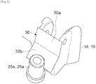
- the figure 2 illustrates a second example of the shape of each of the reinforcing members.
- the reinforcing member 30 has a parallelepipedic shape comprising a first part 30a fixed to the corresponding wheel yoke and second part 30b matching in shape with the corresponding fixing member.
- the figure 3 and 4 illustrates other example shapes for the reinforcing members 26, 27.
- the reinforcing members 26, 27 comprise a first part 26a, 27a that matches the shape of the fixing part of the wheel yoke 14, 16 for its fixing to said yoke, for example by welding, and a second part 26b, 27b matching the shape of the fixing member 25a, 26a for its fixing on said fixing member, for example by welding.
- the shape of the reinforcing members 26, 27, 28, 29 of the figure 1 can be chosen from the forms described with reference to the figures 1 to 4 and may be of the same or different shape.
- the invention is defined in the claims.
- the absorption of forces between the wheel and the body is satisfactory and it is no longer necessary to increase the thickness of the yoke, nor to insert internal reinforcements in each of the half-shells , which facilitates the manufacturing process.
Landscapes
- Engineering & Computer Science (AREA)
- Chemical & Material Sciences (AREA)
- Combustion & Propulsion (AREA)
- Transportation (AREA)
- Mechanical Engineering (AREA)
- Body Structure For Vehicles (AREA)
- Automatic Cycles, And Cycles In General (AREA)
- Vehicle Body Suspensions (AREA)
- Arrangement Or Mounting Of Propulsion Units For Vehicles (AREA)
Claims (8)
- Hinterachsaggregat (10) eines Kraftfahrzeugs, das eine Karosserie, einen hinteren Hilfsrahmen (12), der mit der Karosserie durch Befestigungsorgane (25a, 25b, 26a und 26b) verbunden ist, und Radhalterungen (14, 16, 18, 20), an welchen Radstangen befestigt werden, umfasst, dadurch gekennzeichnet, dass es ein Verstärkungsorgan (26, 27, 28, 29, 30) umfasst, das jeweils direkt zwischen einer Radhalterung (14, 16, 18, 20) und einem entsprechenden Befestigungsorgan (25a, 25b, 26a, 26b) befestigt ist, wobei die Verstärkungsorgane (26, 27, 28, 29, 30) einen ersten Teil (26a, 27a, 28a, 29a, 30a), der an die Form eines Befestigungsteils der entsprechenden Radhalterung (14, 16, 18, 20) angepasst ist, und einen zweiten Teil (26b, 27b, 28b, 29b, 30b), der an die Form des entsprechenden Befestigungsorgans (25a, 25b, 26a, 26b) angepasst ist, umfassen, wobei der erste Teil (26a, 27a, 28a, 29a, 30a) eine U-Form aufweist und der zweite Teil (26b, 27b, 28b, 29b, 30b) eine U-Form aufweist.
- Hinterachsaggregat nach Anspruch 1, wobei die Verstärkungsorgane (26, 27, 28, 29, 30) an dem entsprechenden Befestigungsorgan (25a, 25b, 26a, 26b) in der Nähe des Endes des Befestigungsorgans befestigt sind, das an der Karosserie des Fahrzeugs befestigt ist.
- Hinterachsaggregat nach einem der vorhergehenden Ansprüche, wobei die Verstärkungsorgane (26, 27, 28, 29, 30) aus einem metallischen Material hergestellt sind.
- Hinterachsaggregat nach einem der vorhergehenden Ansprüche, wobei die Verstärkungsorgane (26, 27, 28, 29, 30) die Form einer dünnen Platte aufweisen.
- Hinterachsaggregat nach einem der vorhergehenden Ansprüche, wobei die Verstärkungsorgane (26, 27, 28, 29, 30) an der entsprechenden Radhalterung (14, 16, 18, 20) bzw. am entsprechenden Befestigungsorgan (25a, 25b, 26a, 26b) durch Schweißen befestigt sind.
- Hinterachsaggregat nach einem der vorhergehenden Ansprüche, welches eine obere linke Radhalterung (14), eine untere linke Radhalterung (18), eine obere rechte Radhalterung (16) und eine untere rechte Radhalterung (20) umfasst.
- Hinterachsaggregat nach Anspruch 6, welches ein oberes linkes Verstärkungsorgan (26), das an der oberen linken Radhalterung (14) bzw. an einem oberen linken Befestigungsorgan (25a) befestigt ist, ein oberes rechtes Verstärkungsorgan (27), das an der oberen rechten Radhalterung (16) bzw. an einem oberen rechten Befestigungsorgan (26a) befestigt ist, ein unteres linkes Verstärkungsorgan (28), das an der unteren linken Radhalterung (18) bzw. an einem unteren linken Befestigungsorgan (25b) befestigt ist, und ein unteres rechtes Verstärkungsorgan (29), das an der unteren rechten Radhalterung (20) bzw. an einem unteren rechten Befestigungsorgan (26a) befestigt ist, umfasst.
- Kraftfahrzeug, welches ein Hinterachsaggregat (10) nach einem der vorhergehenden Ansprüche umfasst.
Applications Claiming Priority (1)
| Application Number | Priority Date | Filing Date | Title |
|---|---|---|---|
| FR1900531A FR3091833B1 (fr) | 2019-01-22 | 2019-01-22 | Véhicule automobile comprenant un organe de renfort entre un berceau et une chape de roue |
Publications (2)
| Publication Number | Publication Date |
|---|---|
| EP3686085A1 EP3686085A1 (de) | 2020-07-29 |
| EP3686085B1 true EP3686085B1 (de) | 2023-01-11 |
Family
ID=67262455
Family Applications (1)
| Application Number | Title | Priority Date | Filing Date |
|---|---|---|---|
| EP20151733.1A Active EP3686085B1 (de) | 2019-01-22 | 2020-01-14 | Kraftfahrzeug, das ein verstärkungsorgan zwischen dem achsrahmen und dem radkasten enthält |
Country Status (2)
| Country | Link |
|---|---|
| EP (1) | EP3686085B1 (de) |
| FR (1) | FR3091833B1 (de) |
Family Cites Families (4)
| Publication number | Priority date | Publication date | Assignee | Title |
|---|---|---|---|---|
| US6742808B1 (en) * | 2001-12-10 | 2004-06-01 | Hayes Lemmerz International, Inc. | Cast aluminum vehicle subframe with tension/compression struts |
| DE102012007325B4 (de) * | 2012-04-12 | 2022-05-05 | Audi Ag | Radaufhängung für eine Fünflenker-Hinterachse eines zweispurigen Fahrzeugs |
| KR101906486B1 (ko) * | 2017-03-13 | 2018-10-12 | 서진산업 주식회사 | 용접성 및 내구강성 증대를 위한 끼움부 적용 서브프레임 |
| CN207029301U (zh) * | 2017-07-12 | 2018-02-23 | 荣成华泰汽车有限公司 | 汽车后副车架及汽车 |
-
2019
- 2019-01-22 FR FR1900531A patent/FR3091833B1/fr not_active Expired - Fee Related
-
2020
- 2020-01-14 EP EP20151733.1A patent/EP3686085B1/de active Active
Also Published As
| Publication number | Publication date |
|---|---|
| EP3686085A1 (de) | 2020-07-29 |
| FR3091833B1 (fr) | 2022-03-11 |
| FR3091833A1 (fr) | 2020-07-24 |
Similar Documents
| Publication | Publication Date | Title |
|---|---|---|
| EP1904362B1 (de) | Verfahren zur montage einer kraftfahrzeugachse mit aufhängungsarmen und montiertem querträger zwischen den armen und entsprechende achse | |
| WO2012059597A1 (fr) | Essieu souple pour vehicule automobile en partie colle | |
| FR2922508A1 (fr) | Structure de vehicule automobile | |
| EP1390639A1 (de) | Antischwingungslager und methode zur herstellung solcher | |
| EP3003826B1 (de) | Träger für fahrwerk eines kraftfahrzeugs | |
| EP2436579B1 (de) | Querträgergruppe eines Armaturenbrettes für ein Auto | |
| EP1689598B1 (de) | Flexible achse mit einer quersteifigkeit, die mit hilfe von mindestens einem federtellerformteil erhöht wird, federteller und entsprechendes fahrzeug | |
| EP4313636B1 (de) | Vorrichtung zur begrenzung der bewegung eines fahrzeugstossdämpfers, insbesondere eines kraftfahrzeugstossdämpfers | |
| FR2851958A1 (fr) | Essieu souple pour vehicule automobile a element anti-devers rapporte, vehicule automobile et procede de fabrication correspondants | |
| EP0559542B1 (de) | Kupplung aus einem Stück | |
| WO2012101365A1 (fr) | Dispositif d'assemblage d'un corps d'essieu et procede associe | |
| FR2461601A1 (fr) | Carter de pont arriere du type banjo | |
| EP3686085A1 (de) | Kraftfahrzeug, das ein verstärkungsorgan zwischen dem achsrahmen und dem radkasten enthält | |
| EP0937907B1 (de) | Vorrichtung zum Verbinden des Ankerkerns eines elastischen Gelenks mit einem Aussenteil | |
| FR3139783A1 (fr) | extension de longeronnet arrière pour véhicule automobile | |
| EP3362305B1 (de) | Aufhängungsarm mit unterschiedlichen dicken | |
| FR2864471A1 (fr) | Essieu souple a bras longitudinaux cintres, bras longitudinal et vehicule correspondants | |
| FR2730192A1 (fr) | Dispositif antidevers a barre de torsion pour vehicule automobile | |
| EP0289397B1 (de) | Stossstange für Kraftfahrzeug und damit ausgerüstetes Fahrzeug | |
| FR2921622A1 (fr) | Longeron renforce de chassis d'un vehicule automobile et procede de realisation d'un tel longeron | |
| FR3159786A1 (fr) | Arrangement de châssis pour véhicule automobile | |
| FR2832110A1 (fr) | Poutre de pare-chocs a structure d'entretoise amelioree, module d'extremite longitudinale et vehicule automobile correspondants | |
| FR3151773A1 (fr) | Procédé de production de bras inférieurs de suspension | |
| EP3317131A1 (de) | Aufhängungsvorrichtung für ein kraftfahrzeugrad mit einem arm mit einem blechkörper und einem daran befestigten massiven kopf | |
| WO2020208315A1 (fr) | Renfort de longeron interieur |
Legal Events
| Date | Code | Title | Description |
|---|---|---|---|
| PUAI | Public reference made under article 153(3) epc to a published international application that has entered the european phase |
Free format text: ORIGINAL CODE: 0009012 |
|
| STAA | Information on the status of an ep patent application or granted ep patent |
Free format text: STATUS: THE APPLICATION HAS BEEN PUBLISHED |
|
| AK | Designated contracting states |
Kind code of ref document: A1 Designated state(s): AL AT BE BG CH CY CZ DE DK EE ES FI FR GB GR HR HU IE IS IT LI LT LU LV MC MK MT NL NO PL PT RO RS SE SI SK SM TR |
|
| AX | Request for extension of the european patent |
Extension state: BA ME |
|
| STAA | Information on the status of an ep patent application or granted ep patent |
Free format text: STATUS: REQUEST FOR EXAMINATION WAS MADE |
|
| 17P | Request for examination filed |
Effective date: 20210125 |
|
| RBV | Designated contracting states (corrected) |
Designated state(s): AL AT BE BG CH CY CZ DE DK EE ES FI FR GB GR HR HU IE IS IT LI LT LU LV MC MK MT NL NO PL PT RO RS SE SI SK SM TR |
|
| STAA | Information on the status of an ep patent application or granted ep patent |
Free format text: STATUS: EXAMINATION IS IN PROGRESS |
|
| 17Q | First examination report despatched |
Effective date: 20210323 |
|
| RAP3 | Party data changed (applicant data changed or rights of an application transferred) |
Owner name: RENAULT S.A.S |
|
| RAP3 | Party data changed (applicant data changed or rights of an application transferred) |
Owner name: RENAULT S.A.S |
|
| GRAP | Despatch of communication of intention to grant a patent |
Free format text: ORIGINAL CODE: EPIDOSNIGR1 |
|
| STAA | Information on the status of an ep patent application or granted ep patent |
Free format text: STATUS: GRANT OF PATENT IS INTENDED |
|
| INTG | Intention to grant announced |
Effective date: 20220808 |
|
| GRAS | Grant fee paid |
Free format text: ORIGINAL CODE: EPIDOSNIGR3 |
|
| GRAA | (expected) grant |
Free format text: ORIGINAL CODE: 0009210 |
|
| STAA | Information on the status of an ep patent application or granted ep patent |
Free format text: STATUS: THE PATENT HAS BEEN GRANTED |
|
| AK | Designated contracting states |
Kind code of ref document: B1 Designated state(s): AL AT BE BG CH CY CZ DE DK EE ES FI FR GB GR HR HU IE IS IT LI LT LU LV MC MK MT NL NO PL PT RO RS SE SI SK SM TR |
|
| REG | Reference to a national code |
Ref country code: GB Ref legal event code: FG4D Free format text: NOT ENGLISH |
|
| REG | Reference to a national code |
Ref country code: CH Ref legal event code: EP |
|
| REG | Reference to a national code |
Ref country code: DE Ref legal event code: R096 Ref document number: 602020007429 Country of ref document: DE |
|
| REG | Reference to a national code |
Ref country code: IE Ref legal event code: FG4D Free format text: LANGUAGE OF EP DOCUMENT: FRENCH |
|
| REG | Reference to a national code |
Ref country code: AT Ref legal event code: REF Ref document number: 1543276 Country of ref document: AT Kind code of ref document: T Effective date: 20230215 |
|
| REG | Reference to a national code |
Ref country code: LT Ref legal event code: MG9D |
|
| REG | Reference to a national code |
Ref country code: NL Ref legal event code: MP Effective date: 20230111 |
|
| REG | Reference to a national code |
Ref country code: AT Ref legal event code: MK05 Ref document number: 1543276 Country of ref document: AT Kind code of ref document: T Effective date: 20230111 |
|
| PG25 | Lapsed in a contracting state [announced via postgrant information from national office to epo] |
Ref country code: NL Free format text: LAPSE BECAUSE OF FAILURE TO SUBMIT A TRANSLATION OF THE DESCRIPTION OR TO PAY THE FEE WITHIN THE PRESCRIBED TIME-LIMIT Effective date: 20230111 |
|
| P01 | Opt-out of the competence of the unified patent court (upc) registered |
Effective date: 20230608 |
|
| PG25 | Lapsed in a contracting state [announced via postgrant information from national office to epo] |
Ref country code: RS Free format text: LAPSE BECAUSE OF FAILURE TO SUBMIT A TRANSLATION OF THE DESCRIPTION OR TO PAY THE FEE WITHIN THE PRESCRIBED TIME-LIMIT Effective date: 20230111 Ref country code: PT Free format text: LAPSE BECAUSE OF FAILURE TO SUBMIT A TRANSLATION OF THE DESCRIPTION OR TO PAY THE FEE WITHIN THE PRESCRIBED TIME-LIMIT Effective date: 20230511 Ref country code: NO Free format text: LAPSE BECAUSE OF FAILURE TO SUBMIT A TRANSLATION OF THE DESCRIPTION OR TO PAY THE FEE WITHIN THE PRESCRIBED TIME-LIMIT Effective date: 20230411 Ref country code: LV Free format text: LAPSE BECAUSE OF FAILURE TO SUBMIT A TRANSLATION OF THE DESCRIPTION OR TO PAY THE FEE WITHIN THE PRESCRIBED TIME-LIMIT Effective date: 20230111 Ref country code: LT Free format text: LAPSE BECAUSE OF FAILURE TO SUBMIT A TRANSLATION OF THE DESCRIPTION OR TO PAY THE FEE WITHIN THE PRESCRIBED TIME-LIMIT Effective date: 20230111 Ref country code: HR Free format text: LAPSE BECAUSE OF FAILURE TO SUBMIT A TRANSLATION OF THE DESCRIPTION OR TO PAY THE FEE WITHIN THE PRESCRIBED TIME-LIMIT Effective date: 20230111 Ref country code: ES Free format text: LAPSE BECAUSE OF FAILURE TO SUBMIT A TRANSLATION OF THE DESCRIPTION OR TO PAY THE FEE WITHIN THE PRESCRIBED TIME-LIMIT Effective date: 20230111 Ref country code: AT Free format text: LAPSE BECAUSE OF FAILURE TO SUBMIT A TRANSLATION OF THE DESCRIPTION OR TO PAY THE FEE WITHIN THE PRESCRIBED TIME-LIMIT Effective date: 20230111 |
|
| PG25 | Lapsed in a contracting state [announced via postgrant information from national office to epo] |
Ref country code: SE Free format text: LAPSE BECAUSE OF FAILURE TO SUBMIT A TRANSLATION OF THE DESCRIPTION OR TO PAY THE FEE WITHIN THE PRESCRIBED TIME-LIMIT Effective date: 20230111 Ref country code: PL Free format text: LAPSE BECAUSE OF FAILURE TO SUBMIT A TRANSLATION OF THE DESCRIPTION OR TO PAY THE FEE WITHIN THE PRESCRIBED TIME-LIMIT Effective date: 20230111 Ref country code: IS Free format text: LAPSE BECAUSE OF FAILURE TO SUBMIT A TRANSLATION OF THE DESCRIPTION OR TO PAY THE FEE WITHIN THE PRESCRIBED TIME-LIMIT Effective date: 20230511 Ref country code: GR Free format text: LAPSE BECAUSE OF FAILURE TO SUBMIT A TRANSLATION OF THE DESCRIPTION OR TO PAY THE FEE WITHIN THE PRESCRIBED TIME-LIMIT Effective date: 20230412 Ref country code: FI Free format text: LAPSE BECAUSE OF FAILURE TO SUBMIT A TRANSLATION OF THE DESCRIPTION OR TO PAY THE FEE WITHIN THE PRESCRIBED TIME-LIMIT Effective date: 20230111 |
|
| REG | Reference to a national code |
Ref country code: CH Ref legal event code: PL |
|
| PG25 | Lapsed in a contracting state [announced via postgrant information from national office to epo] |
Ref country code: LU Free format text: LAPSE BECAUSE OF NON-PAYMENT OF DUE FEES Effective date: 20230114 |
|
| REG | Reference to a national code |
Ref country code: BE Ref legal event code: MM Effective date: 20230131 |
|
| REG | Reference to a national code |
Ref country code: DE Ref legal event code: R097 Ref document number: 602020007429 Country of ref document: DE |
|
| PG25 | Lapsed in a contracting state [announced via postgrant information from national office to epo] |
Ref country code: SM Free format text: LAPSE BECAUSE OF FAILURE TO SUBMIT A TRANSLATION OF THE DESCRIPTION OR TO PAY THE FEE WITHIN THE PRESCRIBED TIME-LIMIT Effective date: 20230111 Ref country code: RO Free format text: LAPSE BECAUSE OF FAILURE TO SUBMIT A TRANSLATION OF THE DESCRIPTION OR TO PAY THE FEE WITHIN THE PRESCRIBED TIME-LIMIT Effective date: 20230111 Ref country code: MC Free format text: LAPSE BECAUSE OF FAILURE TO SUBMIT A TRANSLATION OF THE DESCRIPTION OR TO PAY THE FEE WITHIN THE PRESCRIBED TIME-LIMIT Effective date: 20230111 Ref country code: LI Free format text: LAPSE BECAUSE OF NON-PAYMENT OF DUE FEES Effective date: 20230131 Ref country code: EE Free format text: LAPSE BECAUSE OF FAILURE TO SUBMIT A TRANSLATION OF THE DESCRIPTION OR TO PAY THE FEE WITHIN THE PRESCRIBED TIME-LIMIT Effective date: 20230111 Ref country code: DK Free format text: LAPSE BECAUSE OF FAILURE TO SUBMIT A TRANSLATION OF THE DESCRIPTION OR TO PAY THE FEE WITHIN THE PRESCRIBED TIME-LIMIT Effective date: 20230111 Ref country code: CZ Free format text: LAPSE BECAUSE OF FAILURE TO SUBMIT A TRANSLATION OF THE DESCRIPTION OR TO PAY THE FEE WITHIN THE PRESCRIBED TIME-LIMIT Effective date: 20230111 Ref country code: CH Free format text: LAPSE BECAUSE OF NON-PAYMENT OF DUE FEES Effective date: 20230131 |
|
| PLBE | No opposition filed within time limit |
Free format text: ORIGINAL CODE: 0009261 |
|
| STAA | Information on the status of an ep patent application or granted ep patent |
Free format text: STATUS: NO OPPOSITION FILED WITHIN TIME LIMIT |
|
| PG25 | Lapsed in a contracting state [announced via postgrant information from national office to epo] |
Ref country code: SK Free format text: LAPSE BECAUSE OF FAILURE TO SUBMIT A TRANSLATION OF THE DESCRIPTION OR TO PAY THE FEE WITHIN THE PRESCRIBED TIME-LIMIT Effective date: 20230111 Ref country code: BE Free format text: LAPSE BECAUSE OF NON-PAYMENT OF DUE FEES Effective date: 20230131 |
|
| 26N | No opposition filed |
Effective date: 20231012 |
|
| PG25 | Lapsed in a contracting state [announced via postgrant information from national office to epo] |
Ref country code: SI Free format text: LAPSE BECAUSE OF FAILURE TO SUBMIT A TRANSLATION OF THE DESCRIPTION OR TO PAY THE FEE WITHIN THE PRESCRIBED TIME-LIMIT Effective date: 20230111 Ref country code: IE Free format text: LAPSE BECAUSE OF NON-PAYMENT OF DUE FEES Effective date: 20230114 |
|
| PG25 | Lapsed in a contracting state [announced via postgrant information from national office to epo] |
Ref country code: IT Free format text: LAPSE BECAUSE OF FAILURE TO SUBMIT A TRANSLATION OF THE DESCRIPTION OR TO PAY THE FEE WITHIN THE PRESCRIBED TIME-LIMIT Effective date: 20230111 |
|
| PG25 | Lapsed in a contracting state [announced via postgrant information from national office to epo] |
Ref country code: BG Free format text: LAPSE BECAUSE OF FAILURE TO SUBMIT A TRANSLATION OF THE DESCRIPTION OR TO PAY THE FEE WITHIN THE PRESCRIBED TIME-LIMIT Effective date: 20230111 |
|
| PG25 | Lapsed in a contracting state [announced via postgrant information from national office to epo] |
Ref country code: BG Free format text: LAPSE BECAUSE OF FAILURE TO SUBMIT A TRANSLATION OF THE DESCRIPTION OR TO PAY THE FEE WITHIN THE PRESCRIBED TIME-LIMIT Effective date: 20230111 |
|
| PG25 | Lapsed in a contracting state [announced via postgrant information from national office to epo] |
Ref country code: CY Free format text: LAPSE BECAUSE OF FAILURE TO SUBMIT A TRANSLATION OF THE DESCRIPTION OR TO PAY THE FEE WITHIN THE PRESCRIBED TIME-LIMIT; INVALID AB INITIO Effective date: 20200114 |
|
| PG25 | Lapsed in a contracting state [announced via postgrant information from national office to epo] |
Ref country code: HU Free format text: LAPSE BECAUSE OF FAILURE TO SUBMIT A TRANSLATION OF THE DESCRIPTION OR TO PAY THE FEE WITHIN THE PRESCRIBED TIME-LIMIT; INVALID AB INITIO Effective date: 20200114 |
|
| PG25 | Lapsed in a contracting state [announced via postgrant information from national office to epo] |
Ref country code: TR Free format text: LAPSE BECAUSE OF FAILURE TO SUBMIT A TRANSLATION OF THE DESCRIPTION OR TO PAY THE FEE WITHIN THE PRESCRIBED TIME-LIMIT Effective date: 20230111 |
|
| PGFP | Annual fee paid to national office [announced via postgrant information from national office to epo] |
Ref country code: GB Payment date: 20260123 Year of fee payment: 7 |
|
| PGFP | Annual fee paid to national office [announced via postgrant information from national office to epo] |
Ref country code: DE Payment date: 20260121 Year of fee payment: 7 |
|
| PGFP | Annual fee paid to national office [announced via postgrant information from national office to epo] |
Ref country code: FR Payment date: 20260123 Year of fee payment: 7 |