EP3686100A1 - Zusammenklappbarer lenker eines fahrrads - Google Patents
Zusammenklappbarer lenker eines fahrrads Download PDFInfo
- Publication number
- EP3686100A1 EP3686100A1 EP19153156.5A EP19153156A EP3686100A1 EP 3686100 A1 EP3686100 A1 EP 3686100A1 EP 19153156 A EP19153156 A EP 19153156A EP 3686100 A1 EP3686100 A1 EP 3686100A1
- Authority
- EP
- European Patent Office
- Prior art keywords
- beams
- tube
- collapsible
- collapsible handlebar
- ferrule
- Prior art date
- Legal status (The legal status is an assumption and is not a legal conclusion. Google has not performed a legal analysis and makes no representation as to the accuracy of the status listed.)
- Withdrawn
Links
Images


Classifications
-
- B—PERFORMING OPERATIONS; TRANSPORTING
- B62—LAND VEHICLES FOR TRAVELLING OTHERWISE THAN ON RAILS
- B62K—CYCLES; CYCLE FRAMES; CYCLE STEERING DEVICES; RIDER-OPERATED TERMINAL CONTROLS SPECIALLY ADAPTED FOR CYCLES; CYCLE AXLE SUSPENSIONS; CYCLE SIDECARS, FORECARS, OR THE LIKE
- B62K21/00—Steering devices
- B62K21/18—Connections between forks and handlebars or handlebar stems
- B62K21/24—Connections between forks and handlebars or handlebar stems readily releasable
-
- B—PERFORMING OPERATIONS; TRANSPORTING
- B62—LAND VEHICLES FOR TRAVELLING OTHERWISE THAN ON RAILS
- B62K—CYCLES; CYCLE FRAMES; CYCLE STEERING DEVICES; RIDER-OPERATED TERMINAL CONTROLS SPECIALLY ADAPTED FOR CYCLES; CYCLE AXLE SUSPENSIONS; CYCLE SIDECARS, FORECARS, OR THE LIKE
- B62K21/00—Steering devices
- B62K21/12—Handlebars; Handlebar stems
Definitions
- the present invention relates to a bicycle and, more particularly, to a collapsible handlebar of a bicycle.
- a bicycle includes a frame and a fork.
- the frame includes a head tube.
- the fork includes a stem rotationally inserted in the head tube.
- a handlebar is connected to the stem.
- the frame and the handlebar are not collapsible. Accordingly, the bicycle is not collapsible and occupies a lot of space when it is parked or stored.
- the frame is collapsible but the handlebar is not collapsible.
- the bicycle is collapsible and occupies less space when it is parked or stored.
- the collapsed bicycle still occupies quite some space because the handlebar is not collapsible.
- the present invention is therefore intended to obviate or at least alleviate the problems encountered in prior art.
- the collapsible handlebar for use on a bicycle includes a ferrule, two tubes and two beams.
- the ferrule is operable to hold a stem of a fork of the bicycle.
- Each of the tubes includes an internal end.
- Each of the beams includes a supportive end for supporting one of the tubes and a connective end pivotally connected to the ferrule.
- the beams are movable relative to each other between a close position and a distant position.
- the internal ends of the tubes are located near and connected to each other when the beams are in the close position.
- a collapsible handlebar includes two tubes 12 and 14, two beams 20 and 30, two connectors 40 and a ferrule 50 according to the preferred embodiment of the present invention.
- the tube 12 includes an internal end 122, an external end 124 and an enlarged portion 126.
- the enlarged portion 126 is formed with an external diameter that gets larger as the enlarged portion 126 extends toward the internal end 122.
- a knob 16 is a tubular element rotationally supported on the tube 12.
- the knob 16 includes skid-proof portions 164 such as ribs formed on an external face thereof.
- the knob 16 is formed with a screw hole 161, a smaller smooth bore 162 and an annular shoulder 163 between and the screw hole 161 and the smooth bore 162.
- the tube 14 is formed with an internal end 142 and an external end 144.
- the internal ends 122 are closer to each other than the external ends 124 and 144 are when the collapsible handlebar is in an extended position ( FIG. 4 ).
- a thread 18 extends on the tube 14 near the internal end 142.
- the thread 18 is shaped in compliance with the screw hole 161.
- the beams 20 and 30 are formed as mirror images of each other.
- the beam 20 includes a supportive end 22 and a connective end 24.
- the supportive end 22 supports the tube 12.
- the beam 30 is formed with a supportive end 32 and a connective end 34.
- the supportive end 32 supports the tube 14.
- the connective ends 24 and 34 are pivotally connected to the ferrule 50.
- the beams 20 and 30 are pivoted relative to each other between a close position and a distant position.
- the collapsible handlebar is in the extended position as the beams 20 and 30 are in the close position.
- the collapsible handlebar is in the collapsed position as the beams 20 and 30 in the distant position.
- the internal end 122 of the first tube 12 is located close to the internal end 142 of the second tube 14 as the beams 20 and 30 are in the close position.
- the internal end 122 of the first tube 12 is located far from the internal end 142 of the second tube 14 as the beams 20 and 30 are moved to the close position as indicated by arrow heads A1 and A2.
- the combination of the beam 20 with the tube 12 can be located on a side of the ferrule 50 and the combination of the beam 30 with the tube 14 can be located on another side of the ferrule 50.
- the beam 20 includes a collar 222 formed at the supportive end 22 and two rings 242 formed at the connective end 24.
- An axis of the collar 222 extends substantially perpendicular to a length of the beam 20.
- An axis of the rings 242 extends substantially parallel to the length of the beam 20.
- the tube 12 includes a portion inserted in and connected to the collar 222 by welding for example. Thus, the tube 12 is not rotatable relative to the beam 20.
- the beam 30 includes a collar 322 formed at the supportive end 32 and two rings 342 formed at the connective end 34.
- An axis of the collar 322 extends substantially perpendicular to a length of the beam 30.
- An axis of the rings 342 extends substantially parallel to the length of the beam 30.
- the tube 14 includes a portion inserted in and connected to the collar 322 by welding for example. Thus, the tube 14 is not rotatable relative to the beam 30.
- Each of the connectors 40 includes a threaded sleeve 42 and a threaded bolt 44.
- the threaded sleeve 42 includes an open end, a closed end, a head 422 formed at the closed end, and a thread (not numbered) extending on an internal face.
- the threaded bolt 44 includes a head 442 formed at an end and a thread (not numbered) extending around the periphery thereof.
- the ferrule 50 is a C-shaped element that extends about an axis 54.
- the ferrule 50 includes two C-shaped edges 52 and two rectilinear edges (not numbered). There is a gap 56 between the rectilinear edges.
- the ferrule 50 further includes two lugs 53 formed on two sides thereof. Each of the lugs 53 includes an aperture 531 in an upper portion and a stop 532 on a lower portion.
- the ferrule 50 further includes at least one protuberance 58 formed near each of the rectilinear edges. Preferably, two protuberances 58 are formed near each of the rectilinear edges.
- One of the lugs 53 (the "right lug") is located between the rings 242.
- the threaded sleeve 42 of one of the connectors 40 (the “first connector") is inserted in the rings 242 and the left lug 53 before it is engaged with the threaded bolt 44 of the first connector 40.
- the beam 20 is pivotally connected to the ferrule 50.
- the rings 242 are located between the heads 422 and 442 of the first connector 40.
- the remaining one of the lugs 53 (the "left lug") is located between the rings 342.
- the threaded sleeve 42 of the remaining one of the connectors 40 (the “second connector") is inserted in the rings 342 and the left lug 53 before it is engaged with the threaded bolt 44 of the second connector 40.
- the beam 30 is pivotally connected to the ferrule 50.
- the rings 342 are located between the heads 422 and 442 of the second connector 40.
- the fork 60 includes a stem 62 pivotally inserted in a head tube of a frame of the bicycle.
- the ferrule 50 is located on and around the stem 62.
- Two fasteners 51 are inserted in the protuberances 58 to bring the rectilinear edges of the ferrule 50 toward each other, thereby rendering the ferrule 50 tight on and around the stem 62.
- the ferrule 50 is connected to the stem 62, avoiding their movement relative to each other.
- the collapsible handlebar is in the collapsed position as the beams 20 and 30 in the distant position.
- the tubes 12 and 14 respectively hang on the beams 20 and 30, which are supported on the fork 60.
- the stops 532 abut against the beams 20 and 30, respectively, thereby keeping the fork 60 from the tubes 12 and 14 from the fork 60.
- the collapsible handlebar is moved to the extended position as the beams 20 and 30 are pivoted to the close position as indicated by arrowheads A3 and A4.
- the internal end 122 of the first tube 12 is located very close to the internal end 142 of the second tube 14.
- the collapsible handlebar 10 is kept in the extended position.
- the knob 16 is rotated in a direction relative to the tube 14 so that the screw hole 161 receives the thread 18.
- the annular shoulder 163 abuts against the enlarged portion 126, thereby pushing the internal end 122 of the tube 12 toward the internal end 142 of the tube 14 as indicated by an arrowhead A5.
- the internal end 122 of the tube 12 gets closer to the internal end 142 of the tube 14 as the thread 18 gets tighter in the screw hole 161.
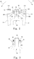
- the beam 20 (or 30) extends along a length L1.
- the collar 222 (or 322) extends around an axis L2.
- the tube 12 (or 14) extends along the axis L2 of the collar 222 (or 322).
- the rings 242 (or 342) and the right (or left) lug 53 extend about an axis L3.
- the angle ⁇ 1 is larger than the angle ⁇ 2.
- the bottom of the knob 16 is located at a height H above the axis L3.
Landscapes
- Engineering & Computer Science (AREA)
- Mechanical Engineering (AREA)
- Steering Devices For Bicycles And Motorcycles (AREA)
Priority Applications (1)
| Application Number | Priority Date | Filing Date | Title |
|---|---|---|---|
| EP19153156.5A EP3686100A1 (de) | 2019-01-22 | 2019-01-22 | Zusammenklappbarer lenker eines fahrrads |
Applications Claiming Priority (1)
| Application Number | Priority Date | Filing Date | Title |
|---|---|---|---|
| EP19153156.5A EP3686100A1 (de) | 2019-01-22 | 2019-01-22 | Zusammenklappbarer lenker eines fahrrads |
Publications (1)
| Publication Number | Publication Date |
|---|---|
| EP3686100A1 true EP3686100A1 (de) | 2020-07-29 |
Family
ID=65200683
Family Applications (1)
| Application Number | Title | Priority Date | Filing Date |
|---|---|---|---|
| EP19153156.5A Withdrawn EP3686100A1 (de) | 2019-01-22 | 2019-01-22 | Zusammenklappbarer lenker eines fahrrads |
Country Status (1)
| Country | Link |
|---|---|
| EP (1) | EP3686100A1 (de) |
Citations (5)
| Publication number | Priority date | Publication date | Assignee | Title |
|---|---|---|---|---|
| US1756339A (en) * | 1928-01-19 | 1930-04-29 | Broberg Charles Emanuel | Adjustable handlebar for bicycles, motor bicycles, and the like vehicles |
| CN2803904Y (zh) * | 2005-07-13 | 2006-08-09 | 黎泳沛 | 螺纹套筒限位弹簧防松旋转式可分拆折叠器 |
| CN201895748U (zh) * | 2010-11-29 | 2011-07-13 | 黎泳沛 | 一种半圆凸条螺纹套筒双夹式对锁折叠车把手 |
| US20140165773A1 (en) * | 2011-07-15 | 2014-06-19 | Joaquín Montero Basqueseaux | Bicycle handlebar set |
| CN105523130A (zh) * | 2015-12-28 | 2016-04-27 | 宁波大胜日用制品有限公司 | 一种折叠式双链传动滑板车 |
-
2019
- 2019-01-22 EP EP19153156.5A patent/EP3686100A1/de not_active Withdrawn
Patent Citations (5)
| Publication number | Priority date | Publication date | Assignee | Title |
|---|---|---|---|---|
| US1756339A (en) * | 1928-01-19 | 1930-04-29 | Broberg Charles Emanuel | Adjustable handlebar for bicycles, motor bicycles, and the like vehicles |
| CN2803904Y (zh) * | 2005-07-13 | 2006-08-09 | 黎泳沛 | 螺纹套筒限位弹簧防松旋转式可分拆折叠器 |
| CN201895748U (zh) * | 2010-11-29 | 2011-07-13 | 黎泳沛 | 一种半圆凸条螺纹套筒双夹式对锁折叠车把手 |
| US20140165773A1 (en) * | 2011-07-15 | 2014-06-19 | Joaquín Montero Basqueseaux | Bicycle handlebar set |
| CN105523130A (zh) * | 2015-12-28 | 2016-04-27 | 宁波大胜日用制品有限公司 | 一种折叠式双链传动滑板车 |
Similar Documents
| Publication | Publication Date | Title |
|---|---|---|
| CN105452746B (zh) | 用于管道的卡箍 | |
| US20160368558A1 (en) | Positioning device for a foldable scooter | |
| US8096212B2 (en) | Two-section tool joint | |
| GB2280878A (en) | Foldable bicycle frame. | |
| US11045924B2 (en) | Folding torque wrench with fast adjustable torque value | |
| US20150183096A1 (en) | Screwdriver | |
| EP3686100A1 (de) | Zusammenklappbarer lenker eines fahrrads | |
| JP6403561B2 (ja) | レンズ鏡筒及びそれを有する光学機器 | |
| US10414460B1 (en) | Collapsible handlebar of a bicycle | |
| US8701526B2 (en) | Fork cartridge driver | |
| WO2019052483A1 (zh) | 坐杆夹组件和车辆 | |
| US10710669B2 (en) | Foldable fork for a bicycle | |
| US8905492B2 (en) | Quick-release skewer adapted for use with a cycle | |
| US20170313374A1 (en) | Bicycle accessories connection unit | |
| CN204055219U (zh) | 可调稳定杆连杆总成 | |
| US20230068536A1 (en) | Cable Guiding Element | |
| KR20150054131A (ko) | 길이 조절이 가능한 타이 로드 결합 구조 | |
| JP3220735U (ja) | 自転車の折畳み可能なハンドルバー | |
| US20170059847A1 (en) | Variable magnification device | |
| JP6345003B2 (ja) | 釣竿 | |
| US610736A (en) | Noftbis peters co | |
| US6886966B2 (en) | Collapsible lamp harp | |
| JP7178694B2 (ja) | 折畳み三輪車 | |
| JPWO2018163227A1 (ja) | 折り畳み自転車 | |
| US9156091B2 (en) | Boring head |
Legal Events
| Date | Code | Title | Description |
|---|---|---|---|
| PUAI | Public reference made under article 153(3) epc to a published international application that has entered the european phase |
Free format text: ORIGINAL CODE: 0009012 |
|
| STAA | Information on the status of an ep patent application or granted ep patent |
Free format text: STATUS: REQUEST FOR EXAMINATION WAS MADE |
|
| 17P | Request for examination filed |
Effective date: 20200331 |
|
| AK | Designated contracting states |
Kind code of ref document: A1 Designated state(s): AL AT BE BG CH CY CZ DE DK EE ES FI FR GB GR HR HU IE IS IT LI LT LU LV MC MK MT NL NO PL PT RO RS SE SI SK SM TR |
|
| AX | Request for extension of the european patent |
Extension state: BA ME |
|
| STAA | Information on the status of an ep patent application or granted ep patent |
Free format text: STATUS: EXAMINATION IS IN PROGRESS |
|
| 17Q | First examination report despatched |
Effective date: 20210526 |
|
| STAA | Information on the status of an ep patent application or granted ep patent |
Free format text: STATUS: THE APPLICATION IS DEEMED TO BE WITHDRAWN |
|
| 18D | Application deemed to be withdrawn |
Effective date: 20211207 |