EP3686103B1 - Durch auftrieb angetriebenes passives fahrzeuglufttrocknungssystem und verfahren - Google Patents
Durch auftrieb angetriebenes passives fahrzeuglufttrocknungssystem und verfahren Download PDFInfo
- Publication number
- EP3686103B1 EP3686103B1 EP19212723.1A EP19212723A EP3686103B1 EP 3686103 B1 EP3686103 B1 EP 3686103B1 EP 19212723 A EP19212723 A EP 19212723A EP 3686103 B1 EP3686103 B1 EP 3686103B1
- Authority
- EP
- European Patent Office
- Prior art keywords
- gap
- vehicle
- ducts
- duct
- air
- Prior art date
- Legal status (The legal status is an assumption and is not a legal conclusion. Google has not performed a legal analysis and makes no representation as to the accuracy of the status listed.)
- Active
Links
Images



Classifications
-
- B—PERFORMING OPERATIONS; TRANSPORTING
- B64—AIRCRAFT; AVIATION; COSMONAUTICS
- B64D—EQUIPMENT FOR FITTING IN OR TO AIRCRAFT; FLIGHT SUITS; PARACHUTES; ARRANGEMENT OR MOUNTING OF POWER PLANTS OR PROPULSION TRANSMISSIONS IN AIRCRAFT
- B64D47/00—Equipment not otherwise provided for
-
- B—PERFORMING OPERATIONS; TRANSPORTING
- B60—VEHICLES IN GENERAL
- B60H—ARRANGEMENTS OF HEATING, COOLING, VENTILATING OR OTHER AIR-TREATING DEVICES SPECIALLY ADAPTED FOR PASSENGER OR GOODS SPACES OF VEHICLES
- B60H1/00—Heating, cooling or ventilating devices
-
- B—PERFORMING OPERATIONS; TRANSPORTING
- B64—AIRCRAFT; AVIATION; COSMONAUTICS
- B64C—AEROPLANES; HELICOPTERS
- B64C1/00—Fuselages; Constructional features common to fuselages, wings, stabilising surfaces or the like
- B64C1/40—Sound or heat insulation, e.g. using insulation blankets
-
- B—PERFORMING OPERATIONS; TRANSPORTING
- B01—PHYSICAL OR CHEMICAL PROCESSES OR APPARATUS IN GENERAL
- B01D—SEPARATION
- B01D53/00—Separation of gases or vapours; Recovering vapours of volatile solvents from gases; Chemical or biological purification of waste gases, e.g. engine exhaust gases, smoke, fumes, flue gases, aerosols
- B01D53/26—Drying gases or vapours
- B01D53/265—Drying gases or vapours by refrigeration (condensation)
-
- B—PERFORMING OPERATIONS; TRANSPORTING
- B64—AIRCRAFT; AVIATION; COSMONAUTICS
- B64C—AEROPLANES; HELICOPTERS
- B64C1/00—Fuselages; Constructional features common to fuselages, wings, stabilising surfaces or the like
-
- B—PERFORMING OPERATIONS; TRANSPORTING
- B64—AIRCRAFT; AVIATION; COSMONAUTICS
- B64D—EQUIPMENT FOR FITTING IN OR TO AIRCRAFT; FLIGHT SUITS; PARACHUTES; ARRANGEMENT OR MOUNTING OF POWER PLANTS OR PROPULSION TRANSMISSIONS IN AIRCRAFT
- B64D13/00—Arrangements or adaptations of air-treatment apparatus for aircraft crew or passengers, or freight space
- B64D13/06—Arrangements or adaptations of air-treatment apparatus for aircraft crew or passengers, or freight space the air being conditioned
- B64D13/08—Arrangements or adaptations of air-treatment apparatus for aircraft crew or passengers, or freight space the air being conditioned the air being heated or cooled
-
- B—PERFORMING OPERATIONS; TRANSPORTING
- B64—AIRCRAFT; AVIATION; COSMONAUTICS
- B64D—EQUIPMENT FOR FITTING IN OR TO AIRCRAFT; FLIGHT SUITS; PARACHUTES; ARRANGEMENT OR MOUNTING OF POWER PLANTS OR PROPULSION TRANSMISSIONS IN AIRCRAFT
- B64D13/00—Arrangements or adaptations of air-treatment apparatus for aircraft crew or passengers, or freight space
- B64D13/06—Arrangements or adaptations of air-treatment apparatus for aircraft crew or passengers, or freight space the air being conditioned
- B64D2013/0603—Environmental Control Systems
- B64D2013/0662—Environmental Control Systems with humidity control
-
- B—PERFORMING OPERATIONS; TRANSPORTING
- B64—AIRCRAFT; AVIATION; COSMONAUTICS
- B64D—EQUIPMENT FOR FITTING IN OR TO AIRCRAFT; FLIGHT SUITS; PARACHUTES; ARRANGEMENT OR MOUNTING OF POWER PLANTS OR PROPULSION TRANSMISSIONS IN AIRCRAFT
- B64D13/00—Arrangements or adaptations of air-treatment apparatus for aircraft crew or passengers, or freight space
- B64D13/06—Arrangements or adaptations of air-treatment apparatus for aircraft crew or passengers, or freight space the air being conditioned
- B64D2013/0603—Environmental Control Systems
- B64D2013/0688—Environmental Control Systems with means for recirculating cabin air
-
- F—MECHANICAL ENGINEERING; LIGHTING; HEATING; WEAPONS; BLASTING
- F24—HEATING; RANGES; VENTILATING
- F24F—AIR-CONDITIONING; AIR-HUMIDIFICATION; VENTILATION; USE OF AIR CURRENTS FOR SCREENING
- F24F7/00—Ventilation
Definitions
- the present disclosure generally relates to moisture control. More particularly, the present disclosure relates to devices and methods for passively controlling moisture within a vehicle.
- the outer wall of an aircraft experiences temperature variations during a flight.
- the outer wall can be relatively warm while the aircraft is on the ground or at low altitude, and relatively cold at higher altitudes.
- An insulation layer is positioned along the outer wall to address the temperature changes and maintain a more constant temperature within the cabin of the aircraft.
- the insulation layer is typically formed from a waterproof material.
- the insulation layer is waterproof, the liquid can flow along the insulation layer and drain into the bilge.
- structures and/or supports can protrude through the insulation layer.
- support members that hold monuments and bins extend through the insulation layer and into the cabin.
- the insulation layer can come with predefined holes for the support members to extend through the insulation layer. When the liquid thaws, it can drip down through the holes and into the cabin.
- a fuselage has an intermediate space provided between a shell element and a structural element, where the intermediate space is ventilatable by an air flow of the inner chamber.
- the intermediate space is connected with an exhaust air/supply air connector of an inner chamber for forming the ventilated air flow as exhaust/supply air flow.
- the shell element is provided with an insulation element, where the shell element is formed in a multi-shelled manner.
- a system for air-conditioning at least a partial area of an aircraft comprises an air supply device for providing air to be supplied to an area of the aircraft to be ventilated at a desired temperature and a desired pressure.
- a supply air duct is connected to the air supply device at a first end.
- a second end of the supply air duct is connected to an air inlet which opens into the aircraft area to be ventilated near the ground.
- a control device is set up to ensure that the air provided by the air supply device enters the aircraft area to be ventilated via the air inlet at such a speed that the air is distributed in the aircraft area to be ventilated close to the ground and is present in the aircraft area to be ventilated Heat sources rise and that the air provided by the air supply device enters the aircraft area to be ventilated via the air inlet at a temperature such that a desired room temperature is established in the aircraft area to be ventilated.
- a vehicle comprising an outer wall, an insulation layer that extends along the outer wall, a gap formed between the outer wall and the insulation layer, a cabin area formed within the insulation layer at a center of the vehicle, and a system to passively remove moisture from air within the vehicle.
- the system comprises a first duct that extends through the insulation layer, the first duct comprising an inlet positioned in the cabin area of the vehicle and an outlet positioned in the gap formed between the outer wall and the insulation layer.
- the system further comprises a second duct that extends through the insulation layer, the second duct comprising an inlet positioned in the gap and an outlet positioned in the cabin area.
- the second duct is positioned in the vehicle vertically below the first duct, the inlet and the outlet of each of the first and second ducts are open and unattached to an air moving device.
- the first and second ducts are positioned for enabling air within the vehicle to passively move through the first duct and into the gap, move downward through the gap where moisture in the air freezes against the outer wall, and move out of the second duct and back into cabin area.
- the first duct has a smaller minimum cross-sectional area than the second duct.
- the method comprises (a) passively moving air from a cabin area into one or more first ducts that extends through an insulation layer and into a gap formed between the insulation layer and an outer wall of the vehicle, (b) cooling the air within the gap that flows against the outer wall, where the outer wall is at a temperature below the freezing temperature of water and causes cooling of air flowing along the outer wall and moving the air vertically downward within the gap towards one or more second ducts, (c) freezing moisture in the air in the gap that comes into contact with the outer wall, (d) passively moving the air through the one or more second ducts and back into the cabin area, (e) preventing the air from moving along the gap vertically below the one or more second ducts.
- the one or more first ducts have a smaller minimum cross-sectional area than the one or more second ducts.
- the present application is directed to ventilation systems for controlling moisture in a vehicle.
- the ventilation systems include one or more inlet ducts that extend through an inner wall. An inlet end is positioned within an interior space of the vehicle, and an outlet end is positioned in a gap formed at an outer wall. The outer wall is cooled by the outside air during operation of the vehicle at high altitude flight and experiences a decrease in temperature below the freezing temperature of water responsive to an increase in altitude of the vehicle (e.g., an altitude above 10,000 feet (3,000 m)).
- the ventilation system also includes one or more outlet ducts that extend through the inner wall and are positioned vertically below the one or more inlet ducts. The outlet ducts include an inlet end in the gap and an outlet end in the interior space of the vehicle.
- the ventilation systems provide for passive air flow with air moving into the one or more inlet ducts and into the gap.
- the air in the gap may move along and/or flow against the outer wall where the air is cooled and vertically drop along the gap. Moisture in the air within the gap freezes against the outer wall while the air moves in the gap to control the humidity of the air.
- the air in the gap then moves through the one or more outlet ducts and back into the interior space.
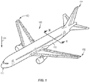
- Figure 1 illustrates one type of vehicle 100, namely an aircraft 100.
- the aircraft 100 includes a nose 101, wings 102, a fuselage 103, and a tail 104.
- Figure 1 also illustrates a downward arrow 105 indicating the expected direction in which the force of gravity will pull objects, such as moisture, onboard an aircraft 100 in a nominal operational profile.
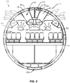
- Figure 2 is a cross-sectional, schematic view of the aircraft 100 indicated by view arrows II-II in Figure 1 .
- Figure 2 illustrates a simplified version of a portion of the aircraft fuselage 103 that includes an outer wall 40.
- the fuselage 103 also includes an insulation layer 41 positioned inward towards a center of the fuselage 103 from the outer wall 40.
- a gap 42 is formed between the outer wall 40 and the insulation layer 41.
- the fuselage 103 also includes a cabin 113 that includes a floor 110, ceiling 111, and aesthetic fascia walls 112.
- the cabin 113 can be equipped with seats 114 and luggage compartments 115 to accommodate passengers.
- Respiration and other sources of water cause moisture 120 to be absorbed or form in the air in the cabin 113.
- warm exhaled air includes moisture 120 that rises upward through the luggage compartments 115. Some of this warm and moist air rises through the ceiling 111 and into the crown space 43 of the cabin 113. Furthermore, some warm air continues to rise upward through the insulation layer 41 and into the gap 42 formed between the insulation layer 41 and the outer wall 40.
- a ventilation system 10 is positioned to passively ventilate the air within the vehicle 100.
- the ventilation system 10 can be located above the cabin 113 to move the air within the crown space 43 and gap 42 between the insulating layer 41 and outer wall 40.
- the ventilation system 10 includes one or more inlet ducts 20 and one or more outlet ducts 30.
- the inlet and outlet ducts 20, 30 extend through openings 44 in the insulation layer 41 to move the air between the crown space 43 and the gap 42.
- the inlet ducts 20 can be positioned along the upper reaches of the crown space 43 so as to extend through the insulation layer 41 at the upper reaches of the crown space 43, and are configured to move air from the crown space 43 into the gap 42.
- the outlet ducts 30 are positioned vertically below the inlet ducts 20 so as to extend through the insulation layer 41 at a lower region of the crown space 43, and are configured to move the air from the gap 42 into the crown space 43.
- the ventilation system 10 can include various numbers of inlet ducts 20 and outlet ducts 30. This can include a single inlet duct 20 and a corresponding single outlet duct 30.
- the ventilation system 10 can also include multiple inlet ducts 20 and outlet ducts 30.
- the inlet ducts 20 and outlet ducts 30 can be positioned in pairs or in uneven numbers.
- the inlet ducts 20 and outlet ducts 30 can extend along the length of the fuselage 103, or can extend along one or more limited sections.
- the inlet ducts 20 and outlet ducts 30 can be positioned along both starboard and port sides of the aircraft 100 or along just a single side.
- the ventilation system 10 uses the buoyancy of air to create airflow between the crown space 43 and the gap 42. Warm air rises within the crown space 43. At this vertically elevated position, the air moves through the one or more inlet ducts 20 and into the gap 42. Once in the gap 42, the air in the gap may move along and/or flow against the outer wall 40, where the outer wall 40 experiences a decrease in temperature below the freezing temperature of water at an increased altitude of the vehicle, and cools the air in the gap 42. The cool air along the outer wall 40, becoming more dense than the air in the cabin 113, then vertically sinks within the gap 42 to a lower vertical position.
- the cool air has a higher pressure and moves through the one or more outlet ducts 30 and back into the crown space 43 which has relatively warmer air at a lower air pressure.
- the amount of air flow within the ventilation system 10 depends upon the vertical height difference between the one or more inlet ducts 20 and one or more outlet ducts 30, and the temperature differential between the crown space 43 and the gap 42.
- the movement of air along the gap 42 also provides for removing moisture from the air.
- the temperature of the outer wall 40 eventually decreases to a temperature below the freezing temperature of water. This cooling causes the moisture 120 in the air to condense out of the air in the gap 42 and freeze as ice onto the outer wall 40.
- Drains 60 located at the lower reaches of the gap 42 capture the water and direct it way, such as towards a bottom 116 of the fuselage 103. This prevents the moisture 120 from potentially moving along the support members 161 and into the cabin 113.
- the ventilation system 10 uses buoyancy driven air flow to circulate through the crown space 43 and gap 42.
- the ventilation system 10 does not include air movement devices such as fans, air conditioning units, etc. to move the air.
- the one or more inlet ducts 20 and outlet ducts 30 are exposed within the crown space 43 and gap 42 and provide conduits for air flow.
- the gap 42 includes an air seal 50 vertically below the one or more outlet ducts 30.
- the air seal 50 acts as a block to direct the air through the one or more outlet ducts 30 and into the crown space 43.
- the air seal 50 can be positioned immediately below the one or more outlet ducts 30 to prevent the air that is moving downward in the gap 42 from moving vertically lower than and beyond the one or more outlet ducts 30.
- the air seal 50 can also be positioned farther below the one or more outlet ducts 30 to limit the amount of air that moves below the one or more outlet ducts 30.
- the air seal 50 can include a single sealing structure, or multiple separate structures positioned along the vehicle 100.
- the drains 60 are positioned in the gap 42 to remove the moisture.
- the drains 60 can be located along the gap 42 vertically below the one or more outlet ducts 30. Some examples includes one or more of the drains 60 positioned in the gap 42 vertically between the one or more outlet ducts 30 and the air seal 50. This positioning provides for the drains 60 to capture the moisture that is in the gap 42 and that moves downward due to gravity.
- the drains 60 can be positioned at other vertical locations within the gap 42, including vertically equal to the one or more outlet ducts 30.
- the one or more inlet ducts 20 are a conduit for air to move from the crown space 43 and into the gap 42.
- the inlet ducts 20 include an elongated body 23 with a first inlet end 21 and a second outlet end 22.
- the body 23 is sized to extend through the insulation layer 41 with the inlet end 21 being exposed within the crown space 43 to receive the air and the outlet end 22 positioned in the gap 42.
- the inlet duct 20 includes a cross-sectional area that can include a variety of different shapes and sizes.
- One or more of the inlet ducts 20 can be designed to prevent condensation from forming within the interior at a point where liquid can drip out into the crown space 43.
- the inlet ducts 20 are oriented for the inlet end 21 to be positioned vertically above the outlet end 22. Condensation that forms within the interior of the inlet ducts 20 is then directed into the gap 42 wherein the moisture can move along the gap 42 to the drains 60.
- the one or more inlet ducts 20 can be constructed to reduce or eliminate the accumulation of condensation along a section or entirety of the interior.
- Figure 5 includes an inlet duct 20 with an insulating layer 24 positioned on an interior side at the inlet end 21.
- the insulating layer 24 prevents or reduces the moisture-laden air that enters into the inlet end 21 from condensing along this interior section of the inlet duct 20.
- the insulation layer 24 is positioned along the section of the inlet duct 20 that is located in the gap 42. The moisture in the air tends to condense because this section is exposed to a lower temperature than the section of the inlet duct 20 in the crown space 43.
- the insulating layer 24 can be constructed from a variety of materials, including but not limited to adhered closed cell foam insulation, cold side enclosed fiberglass wool insulation, enclosed open cell foam, and composite insulation. In some examples, the entire duct 20 is constructed from closed cell foam insulation and does not include a separate insulation layer 24.
- the one or more outlet ducts 30 are a conduit for air to move from the gap 42 and into the crown space 43.
- Figure 6 illustrates an outlet duct 30 that includes an elongated body 33 with a first inlet end 31 and a second outlet end 32.
- the body 33 is sized to extend through the insulation layer 41 with the inlet end 31 being exposed within the gap 42 and the outlet end 32 being exposed within the crown space 43.
- Figure 7 illustrates an inlet duct 20 extending through the insulation layer 41.
- the inlet end 21 and adjacent section are positioned in the crown space 43 and the outlet end 22 and adjacent section are positioned in the gap 42.
- the inlet duct 20 can be angled for the inlet end 21 to be vertically higher than the outlet end 22. This orientation provides for any condensation to be directed into the gap 42 where it can eventually move into a drain 60.
- the inlet duct 20 extends through an opening 44 in the insulation layer 41.
- a flap 85 can be attached to the insulation layer 41 and extend over the inlet duct 20 that is positioned in the gap 42.
- the flap 85 is sealed to the insulation layer 41 vertically above the opening 44.
- the flap 85 can prevent uninsulated edges along the opening 44 to prevent condensation from leaking through the insulating layer 41 and into the crown space 43.
- the flap 85 can be constructed from an insulating material, and can have the same construction as the insulating layer 41.
- the flap 85 can also be used on the outlet duct 30 in a similar manner to reduce condensation from leaking into the crown space 43.
- the inlet duct 20 and outlet duct 30 extend through openings 44 in the insulating layer 41.
- the openings 44 can be cut into the insulating layer 41 and sized to accommodate the ducts 20, 30.
- the insulating layer 41 is solid, such as a molded foam.
- Figure 9 illustrates the opening 44 created between two shingled, overlapping insulation layers 41a, 41b. The overlapping sections 45 of the insulating layers 41 are sealed to prevent condensation leak into the crown space 43.
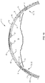
- Figure 10 illustrates a ventilation system 10 with one or more inlet ducts 20 and outlet ducts 30 positioned along the port and starboard sides of the aircraft 100.
- the inlet ducts 20 are positioned along the upper reaches of the crown space 43 vertically above the outlet ducts 30.
- the different inlet ducts 20 can each be positioned at the same or different elevations within the crown space 43.
- the outlet ducts 30 are positioned along the lower reaches of the crown space 43 vertically below the inlet ducts 20.
- the different outlet ducts 30 can be positioned at the same or different elevations within the crown space 43.
- the inlet and outlet ducts 20, 30 each extend to the gap 42 formed between the outer wall 40 and the insulating layer 41.
- the outlet ducts 30 can be positioned with the inlet end 31 facing downward in the gap 42. This positioning can prevent moisture that is in the gap 42 vertically above the outlet ducts 30 from moving vertically downward in the gap 42 and entering into the outlet ducts 30.
- the seal 50 is formed between the insulating layer 41 and one or more additional insulation layers 72.
- Figure 10 specifically includes the insulation layer 41 extending between two additional insulation layers 72.
- the insulation layers 41, 72 prevent air from flowing vertically below the seal 50.
- the drains 60 are positioned vertically below the outlet ducts 30 to remove the moisture from the gap 42.
- the drains 60 can be formed between two or more of the insulation layers 41, 72.
- the ventilation system 10 can be installed originally during the manufacturing process of the vehicle 100.
- the ventilation system 10 can also be installed in an existing vehicle 100.
- Figure 11 illustrates a method of passively ventilating air within a vehicle 100 with a ventilation system 10.
- the method includes passively moving air from the cabin area 113 into the first duct 20 (block 200).
- the air is moved into the gap 42 and into contact with an outer wall 40 of the vehicle 100 (block 202). While the air is in the gap 42, the air is cooled as it contacts and flows against the outer wall 40 (block 204).
- the cooled air along the outer wall 40 moves vertically downward within the gap 42 towards the second duct 30 (block 206).
- the moisture in the air freezes against the outer wall 40 and is removed from the air (block 208).
- the air is prevented from moving vertically below the second duct 30 (block 210).
- the air is the gap 42 is passively moved through the second duct 30 and back into the cabin area 113 (block 212).
- FIG 11 is described with the air moving through an inlet duct 20 and an outlet duct 30.
- the ventilation system 10 can include various numbers of inlet ducts 20 and outlet ducts 30 with the air moving through each of the various inlet and outlet ducts 20, 30 to control the moisture in the air.
- the inner wall can include a variety of constructions. Some examples include the inner wall being the insulation layer 41. Other examples include the inner wall being a fascia wall 112, structural wall, and wall of a luggage compartment 115.
- the outer wall 40 can include the exterior wall of the vehicle 100.
- the outer wall 40 can also be spaced inward the exterior wall and positioned in proximity to exterior wall to change in temperature based on the altitude of the vehicle 100.
- Vehicles 100 include but are not limited to manned aircraft, unmanned aircraft, manned spacecraft, unmanned spacecraft, manned rotorcraft, unmanned rotorcraft, satellites, rockets, missiles, manned terrestrial vehicles, unmanned terrestrial vehicles, manned surface water borne vehicles, unmanned surface water borne vehicles, manned sub-surface water borne vehicles, unmanned sub-surface water borne vehicles, and combinations thereof.
Landscapes
- Engineering & Computer Science (AREA)
- Aviation & Aerospace Engineering (AREA)
- Mechanical Engineering (AREA)
- Chemical & Material Sciences (AREA)
- General Health & Medical Sciences (AREA)
- Health & Medical Sciences (AREA)
- Thermal Sciences (AREA)
- Pulmonology (AREA)
- Physics & Mathematics (AREA)
- Analytical Chemistry (AREA)
- General Chemical & Material Sciences (AREA)
- Oil, Petroleum & Natural Gas (AREA)
- Chemical Kinetics & Catalysis (AREA)
- Duct Arrangements (AREA)
- Air-Conditioning For Vehicles (AREA)
Claims (15)
- Fahrzeug (100) mit:einer äußeren Wand (40);einer Isolierschicht (41), die sich entlang der äußeren Wand (40) erstreckt;einem zwischen der äußeren Wand (40) und der Isolierschicht (41) gebildeten Spalt (42),einem innerhalb der Isolierschicht (41) in der Mitte des Fahrzeugs (100) gebildeten Kabinenbereich (113); undeinem System zum passiven Entfernen von Feuchtigkeit aus der Luft im Fahrzeug (100), wobei das System umfasst:eine erste Leitung (20), die sich durch die Isolierschicht (41) erstreckt, wobei die erste Leitung (20) einen im Kabinenbereich (113) des Fahrzeugs (100) angeordneten Einlass (21) und einen in dem zwischen der äußeren Wand (40) und der Isolierschicht (41) gebildeten Spalt (42) angeordneten Auslass (22) umfasst;eine zweite Leitung (30), die sich durch die Isolierschicht (41) erstreckt, wobei die zweite Leitung (30) einen in dem Spalt (42) angeordneten Einlass (31) und einen in dem Kabinenbereich (113) angeordneten Auslass (32) umfasst; wobei:die zweite Leitung (30) im Fahrzeug (100) vertikal unter der ersten Leitung (20) angeordnet ist;der Einlass (21, 31) und der Auslass (22, 32) der ersten und der zweiten Leitung (20, 30) offen und nicht mit einer Luftbewegungsvorrichtung verbunden sind; unddie erste und die zweite Leitung (20, 30) so angeordnet sind, dass sie es Luft innerhalb des Fahrzeugs (100) ermöglichen, sich passiv durch die erste Leitung (20) und in den Spalt (42) zu bewegen, sich durch den Spalt (42) nach unten zu bewegen, wobei Feuchtigkeit in der Luft an der äußeren Wand (40) gefriert, und sich aus der zweiten Leitung (30) und zurück in den Kabinenbereich (113) zu bewegen,wobei die erste Leitung (20) eine kleinere Mindestquerschnittsfläche hat als die zweite Leitung (30).
- Fahrzeug (100) nach Anspruch 1, ferner mit einer Dichtung (50), die entlang des Spalts (42) vertikal unterhalb der zweiten Leitung (30) angeordnet ist, wobei die Dichtung (50) konfiguriert ist, um zu verhindern, dass Luft entlang des Spalts (42) vertikal unterhalb der zweiten Leitung (30) strömt.
- Fahrzeug (100) nach Anspruch 2, bei dem:die äußere Wand (40) des Fahrzeugs als Reaktion auf eine Zunahme der Höhe des Fahrzeugs (100) eine Temperaturabnahme erfährt;die Isolierschicht (41) eine Außenseite, die der äußeren Wand (40) zugewandt ist, und eine Innenseite umfasst;der Spalt (42) sich von einem Scheitel des Fahrzeugs (100) entlang einer Seitenwand des Fahrzeugs (100) nach unten erstreckt;die erste Leitung (20) den auf der Innenseite der Isolierschicht (41) angeordneten Einlass (21) und den in dem Spalt (42) angeordneten Auslass (22) umfasst;die zweite Leitung (30) den auf der Innenseite der Isolierschicht (41) angeordneten Auslass (32) umfasst;wobei sowohl der Einlass (21) der ersten Leitung (20) als auch der Auslass (32) der zweiten Leitung (30) offen sind und an der Innenseite der Isolierschicht (41) freiliegen;die zweite Leitung (30) vertikal unterhalb der ersten Leitung (20) angeordnet ist; unddie äußere Wand (40), wenn sie einem Temperaturabfall unter die Gefriertemperatur von Wasser ausgesetzt ist, bewirkt, dass Feuchtigkeit in der Luft innerhalb des Spalts (42) an der äußeren Wand (40) gefriert, wenn sich die Luft in dem Spalt (42) von der ersten Leitung (20) zur zweiten Leitung (30) bewegt.
- Fahrzeug (100) nach Anspruch 3, bei dem die äußere Wand (40) eine Außenwand des Fahrzeugs (100) ist.
- Fahrzeug (100) nach Anspruch 3 oder 4, ferner mit einem vertikal unter der zweiten Leitung (30) angeordneten Ablauf (60), der konfiguriert ist, um Feuchtigkeit aufzunehmen, die sich in dem Spalt (42) ansammelt.
- Fahrzeug (100) nach einem der Ansprüche 3 bis 5, bei dem der Einlass der zweiten Leitung (30) im Spalt (42) vertikal nach unten weist, um zu verhindern, dass Feuchtigkeit im Spalt (42) in der zweiten Leitung (30) aufgefangen wird.
- Fahrzeug (100) nach einem der Ansprüche 3 bis 6, bei dem die erste Leitung (20) in der Nähe des Scheitels des Fahrzeugs (100) angeordnet ist und die zweite Leitung (30) entlang der Seitenwand des Fahrzeugs (100) angeordnet ist.
- Fahrzeug (100) nach Anspruch 1 oder 2, wobei das Fahrzeug (100) ein bemanntes Flugzeug, ein unbemanntes Flugzeug, ein bemanntes Raumfahrzeug, ein unbemanntes Raumfahrzeug, ein bemanntes Drehflügelflugzeug, ein unbemanntes Drehflügelflugzeug, ein Satellit, eine Rakete, ein Flugkörper, ein bemanntes Landfahrzeug, ein unbemanntes Landfahrzeug, ein bemanntes Oberflächenwasserfahrzeug, ein unbemanntes Oberflächenwasserfahrzeug, ein bemanntes Unterwasserfahrzeug oder ein unbemanntes Unterwasserfahrzeug ist.
- Verfahren zum passiven Belüften eines Fahrzeugs (100), wobei das Verfahren umfasst:passives Bewegen von Luft aus einem Kabinenbereich (113) in ein oder mehrere erste Leitungen (20), die sich durch eine Isolierschicht (41) und in einen zwischen der Isolierschicht (41) und einer äußeren Wand (40) des Fahrzeugs (100) gebildeten Spalt (42) erstrecken;Kühlen der Luft in dem Spalt (42), die gegen die äußere Wand (40) strömt, wobei die äußere Wand (40) eine Temperatur unterhalb der Gefriertemperatur von Wasser hat und eine Kühlung der Luft bewirkt, die entlang der äußeren Wand (40) strömt, und die Luft in dem Spalt (42) vertikal nach unten zu einem oder mehreren zweiten Kanälen (30) bewegt;Gefrieren der Feuchtigkeit in der Luft in dem Spalt (42), die mit der äußeren Wand (40) in Kontakt kommt;passives Bewegen der Luft durch die ein oder mehreren zweiten Kanäle (30) und zurück in den Kabinenbereich (113); undVerhindern, dass sich die Luft entlang des Spalts (42) vertikal unter den ein oder mehreren zweiten Leitungen (30) bewegt, wobei die ein oder mehreren ersten Leitungen (20) eine kleinere Mindestquerschnittsfläche haben als die ein oder mehreren zweiten Leitungen (30).
- Verfahren nach Anspruch 9, das ferner das Erzeugen einer Luftdruckdifferenz in dem Spalt (42) zwischen den Auslässen (22) der ein oder mehreren ersten Leitungen (20) und den Einlässen (31) der ein oder mehreren zweiten Leitungen (30) umfasst.
- Verfahren nach einem der Ansprüche 9 bis 10, bei dem die Einlässe (21) der ein oder mehreren ersten Leitungen (20) und die Auslässe (32) der ein oder mehreren zweiten Leitungen (30) im Kabinenbereich (113) freiliegen.
- Verfahren nach einem der Ansprüche 9 bis 11, das ferner das Auffangen von Feuchtigkeit in dem Spalt (42) unter den ein oder mehreren zweiten Leitungen (30) und das Abführen der Feuchtigkeit aus dem Spalt (42) umfasst.
- Verfahren nach Anspruch 9, bei dem die ein oder mehreren ersten Leitungen (20) durch die Isolierschicht (41) hindurch angeordnet sind, wobei sich die Einlässe (21) der ein oder mehreren ersten Leitungen (20) im Kabinenbereich (113) und die Auslässe (22) der ein oder mehreren ersten Leitungen (20) innerhalb des zwischen der Isolierschicht (41) und der äußeren Wand (40) gebildeten Spalts (42) befinden; und der eine oder die mehreren zweiten Leitungen (30) durch die Isolierschicht (41) senkrecht unter den ein oder mehreren ersten Leitungen (20) angeordnet sind und Einlässe (31) der ein oder mehreren zweiten Leitungen (30) innerhalb des Spalts (42) angeordnet sind und ein Auslass (32) des einen oder der mehreren zweiten Kanäle (30) im Kabinenbereich (113) angeordnet ist.
- Verfahren nach einem der Ansprüche 9 bis 13, bei dem die ein oder mehreren ersten Kanäle (20) an einem Scheitelpunkt des Fahrzeugs (100) angeordnet sind und die ein oder mehreren zweiten Kanäle (30) entlang einer Seitenwand des Fahrzeugs (100) und über einem Boden des Kabinenbereichs (113) angeordnet sind.
- Verfahren nach einem der Ansprüche 9 bis 14, bei dem der Spalt (42) unterhalb der ein oder mehreren zweiten Leitungen (30) abgedichtet ist und Luft im Spalt (42) daran gehindert ist, sich im Spalt (42) über die ein oder mehreren zweiten Leitungen (30) hinaus nach unten zu bewegen.
Applications Claiming Priority (1)
| Application Number | Priority Date | Filing Date | Title |
|---|---|---|---|
| US16/253,732 US11091270B2 (en) | 2019-01-22 | 2019-01-22 | Buoyancy driven passive vehicle air drying system and method |
Publications (2)
| Publication Number | Publication Date |
|---|---|
| EP3686103A1 EP3686103A1 (de) | 2020-07-29 |
| EP3686103B1 true EP3686103B1 (de) | 2022-07-13 |
Family
ID=68762497
Family Applications (1)
| Application Number | Title | Priority Date | Filing Date |
|---|---|---|---|
| EP19212723.1A Active EP3686103B1 (de) | 2019-01-22 | 2019-11-29 | Durch auftrieb angetriebenes passives fahrzeuglufttrocknungssystem und verfahren |
Country Status (3)
| Country | Link |
|---|---|
| US (1) | US11091270B2 (de) |
| EP (1) | EP3686103B1 (de) |
| CN (1) | CN111452985B (de) |
Families Citing this family (4)
| Publication number | Priority date | Publication date | Assignee | Title |
|---|---|---|---|---|
| US11594802B2 (en) * | 2019-08-16 | 2023-02-28 | Thales Avionics, Inc. | Apparatuses for reducing air condensation in components of satcom antenna subsystem |
| JP7830037B2 (ja) * | 2020-07-23 | 2026-03-16 | ザ・ボーイング・カンパニー | 航空機で使用するための給気システム |
| CN113955123A (zh) * | 2021-12-09 | 2022-01-21 | 中国商用飞机有限责任公司 | 飞机除湿系统 |
| CN118992104B (zh) * | 2024-09-12 | 2025-12-05 | 大连理工大学 | 一种具有舱内加湿和舱壁防湿功能的客机气流组织系统 |
Family Cites Families (24)
| Publication number | Priority date | Publication date | Assignee | Title |
|---|---|---|---|---|
| US3867244A (en) | 1971-12-22 | 1975-02-18 | Boeing Co | Insulation and condensation control blanket |
| YU94078A (en) * | 1977-05-12 | 1984-02-29 | Orenstein & Koppel Ag | Ship cooling container with a cooling arrangement |
| SE465772B (sv) | 1990-03-06 | 1991-10-28 | Ctt Systems Hb | Foerfarande och anordning foer att foerhindra kondens i skalformiga konstruktioner |
| US5897079A (en) | 1997-08-18 | 1999-04-27 | Mcdonnell Douglas Corporation | Air curtain insulating system for aircraft cabin |
| DE19849696A1 (de) | 1998-10-28 | 2000-05-04 | Daimler Chrysler Aerospace | Isolationsaufbau zur Innenisolierung eines Luftfahrzeuges |
| CA2256887C (en) | 1998-12-21 | 2008-07-08 | Indoor Air Technologies Inc. | Environment control system for aircraft having interior condensation problem reduction, cabin air quality improvement, fire suppression and fire venting functions |
| DE10154063B4 (de) | 2001-11-02 | 2013-11-28 | Airbus Operations Gmbh | Doppelwandiger Kernverbund, vorzugsweise Faserverbund |
| US6886783B2 (en) | 2003-02-20 | 2005-05-03 | The Boeing Company | Quick install insulation |
| US7040575B2 (en) | 2004-03-29 | 2006-05-09 | The Boeing Company | Foam composite insulation for aircraft |
| FR2869289B1 (fr) | 2004-04-27 | 2007-07-13 | Eads Sogerma Services Sa | Amenagement interieur des parois du fuselage d'un aeronef. |
| EP1717143B1 (de) | 2005-04-28 | 2008-10-22 | Lufthansa Technik AG | Schalldämmmaterial für die Dämmung in Flugzeugen |
| DE102006012953A1 (de) * | 2006-03-21 | 2007-09-27 | Airbus Deutschland Gmbh | Drainage-Vorrichtung, Flugzeug und Verfahren zum Abführen eines zwischen einer Aussenhaut und einer Innenverkleidung eines Flugzeugs vorhandenen Fluids |
| DE102006023209A1 (de) | 2006-05-17 | 2007-11-22 | Airbus Deutschland Gmbh | Isolierung einer Flugzeugrumpfstruktur |
| DE102006039292B4 (de) | 2006-08-22 | 2010-07-22 | Airbus Deutschland Gmbh | Rahmenelement, Flugzeugklimatisierungssystem sowie Verfahren zur Montage eines Rahmenelements in einem Flugzeug |
| JP2010519119A (ja) | 2007-02-23 | 2010-06-03 | エアバス・オペレーションズ・ゲーエムベーハー | 航空機または宇宙船の胴体、およびそのような胴体を有する航空機または宇宙船、並びにそのような胴体を能動的に断熱する方法 |
| DE102007008986A1 (de) * | 2007-02-23 | 2008-08-28 | Airbus Deutschland Gmbh | Rumpf eines Luft-oder Raumfahrzeugs, und ein entsprechendes Luft-oder Raumfahrzeug |
| DE102007008987B4 (de) | 2007-02-23 | 2012-11-29 | Airbus Operations Gmbh | Rumpf eines Luft-oder Raumfahrzeugs sowie ein Verfahren zum aktiven Isolieren eines solchen Rumpfes |
| DE102007049926A1 (de) * | 2007-10-18 | 2009-04-23 | Airbus Deutschland Gmbh | System und Verfahren zur Klimatisierung zumindest eines Teilbereichs eines Flugzeugs |
| DE102008025389B4 (de) * | 2007-12-21 | 2013-02-28 | Airbus Operations Gmbh | Verfahren zum Isolieren einer Flugzeugkabinenwand bzw. zum Abkühlen oder Aufwärmen von Flugzeugkabinenluft und dazu geeignete Flugzeugkabinenwand |
| DE102008037143A1 (de) | 2008-08-08 | 2010-02-11 | Airbus Deutschland Gmbh | Isolationsaufbau zum thermischen und akustischen Isolieren eines Luftfahrzeugs |
| FR2954474A1 (fr) * | 2009-12-23 | 2011-06-24 | Regis Garoni | Maison d'habitation avec systeme de climatisation passive |
| DE102010034028A1 (de) * | 2010-08-11 | 2012-02-16 | Diehl Aircabin Gmbh | Sandwichplatte für eine Innenwandverkleidung einer Passagierkabine |
| FR2977568B1 (fr) | 2011-07-06 | 2013-08-23 | Airbus Operations Sas | Systeme de drainage des eaux de condensation dans un aeronef |
| US9643728B2 (en) | 2014-03-24 | 2017-05-09 | Honeywell International Inc. | System for preventing water condensation inside aircraft |
-
2019
- 2019-01-22 US US16/253,732 patent/US11091270B2/en active Active
- 2019-11-29 EP EP19212723.1A patent/EP3686103B1/de active Active
-
2020
- 2020-01-20 CN CN202010067315.3A patent/CN111452985B/zh active Active
Also Published As
| Publication number | Publication date |
|---|---|
| US11091270B2 (en) | 2021-08-17 |
| CN111452985B (zh) | 2025-01-07 |
| US20200231290A1 (en) | 2020-07-23 |
| EP3686103A1 (de) | 2020-07-29 |
| BR102019025274A2 (pt) | 2020-09-24 |
| CN111452985A (zh) | 2020-07-28 |
Similar Documents
| Publication | Publication Date | Title |
|---|---|---|
| EP3686103B1 (de) | Durch auftrieb angetriebenes passives fahrzeuglufttrocknungssystem und verfahren | |
| US5897079A (en) | Air curtain insulating system for aircraft cabin | |
| US5577688A (en) | Containment systems for insulation, and insulation elements employing such systems | |
| US8157209B2 (en) | Method for isolating a cabin wall of an aircraft or for cooling or heating of cabin air and a cabin wall suitable therefore | |
| US9873512B2 (en) | Aircraft framework structure with integral ventilation air duct | |
| JPH05505158A (ja) | モノコック構造における復水を防止するための方法並びに装置 | |
| EP2899127B1 (de) | Entfeuchtungssystem zur Verwendung in einem Fahrzeug und Verfahren zur Montage davon | |
| US20080302910A1 (en) | Aircraft Fuselage Heating | |
| EP3476713B1 (de) | Vorrichtungen und verfahren zur abscheidung von feuchtigkeit aus einem strukturelement | |
| EP2456669B1 (de) | Belüftung eines flugkraftstofftanks mit entfeuchtungsvorrichtung | |
| US10988230B2 (en) | Passive moisture management bladder in an aircraft | |
| US9944379B2 (en) | Moisture path close-out and thermal control system and methods of assembling same | |
| CN106428520A (zh) | 航空器隔离系统以及航空器空调和隔离装置 | |
| US9845144B2 (en) | Aircraft and air exchange systems for ventilated cavities of aircraft | |
| EP3904213B1 (de) | Aussenplattenkühlsystem | |
| US10442518B2 (en) | Moisture diversion systems and methods of using same | |
| RU2632057C2 (ru) | Способ воздушного охлаждения тепловыделяющей аппаратуры, расположенной снаружи летательных аппаратов, и система для его реализации | |
| BR102019025274B1 (pt) | Sistema para remover passivamente umidade, e, método de ventilação passiva de ar dentro de um veículo |
Legal Events
| Date | Code | Title | Description |
|---|---|---|---|
| PUAI | Public reference made under article 153(3) epc to a published international application that has entered the european phase |
Free format text: ORIGINAL CODE: 0009012 |
|
| STAA | Information on the status of an ep patent application or granted ep patent |
Free format text: STATUS: THE APPLICATION HAS BEEN PUBLISHED |
|
| AK | Designated contracting states |
Kind code of ref document: A1 Designated state(s): AL AT BE BG CH CY CZ DE DK EE ES FI FR GB GR HR HU IE IS IT LI LT LU LV MC MK MT NL NO PL PT RO RS SE SI SK SM TR |
|
| AX | Request for extension of the european patent |
Extension state: BA ME |
|
| STAA | Information on the status of an ep patent application or granted ep patent |
Free format text: STATUS: REQUEST FOR EXAMINATION WAS MADE |
|
| 17P | Request for examination filed |
Effective date: 20201214 |
|
| RBV | Designated contracting states (corrected) |
Designated state(s): AL AT BE BG CH CY CZ DE DK EE ES FI FR GB GR HR HU IE IS IT LI LT LU LV MC MK MT NL NO PL PT RO RS SE SI SK SM TR |
|
| STAA | Information on the status of an ep patent application or granted ep patent |
Free format text: STATUS: EXAMINATION IS IN PROGRESS |
|
| 17Q | First examination report despatched |
Effective date: 20210318 |
|
| GRAP | Despatch of communication of intention to grant a patent |
Free format text: ORIGINAL CODE: EPIDOSNIGR1 |
|
| STAA | Information on the status of an ep patent application or granted ep patent |
Free format text: STATUS: GRANT OF PATENT IS INTENDED |
|
| INTG | Intention to grant announced |
Effective date: 20220208 |
|
| GRAS | Grant fee paid |
Free format text: ORIGINAL CODE: EPIDOSNIGR3 |
|
| GRAA | (expected) grant |
Free format text: ORIGINAL CODE: 0009210 |
|
| STAA | Information on the status of an ep patent application or granted ep patent |
Free format text: STATUS: THE PATENT HAS BEEN GRANTED |
|
| AK | Designated contracting states |
Kind code of ref document: B1 Designated state(s): AL AT BE BG CH CY CZ DE DK EE ES FI FR GB GR HR HU IE IS IT LI LT LU LV MC MK MT NL NO PL PT RO RS SE SI SK SM TR |
|
| REG | Reference to a national code |
Ref country code: CH Ref legal event code: EP |
|
| REG | Reference to a national code |
Ref country code: DE Ref legal event code: R096 Ref document number: 602019016943 Country of ref document: DE |
|
| REG | Reference to a national code |
Ref country code: AT Ref legal event code: REF Ref document number: 1504150 Country of ref document: AT Kind code of ref document: T Effective date: 20220815 |
|
| REG | Reference to a national code |
Ref country code: IE Ref legal event code: FG4D |
|
| REG | Reference to a national code |
Ref country code: LT Ref legal event code: MG9D |
|
| REG | Reference to a national code |
Ref country code: NL Ref legal event code: MP Effective date: 20220713 |
|
| PG25 | Lapsed in a contracting state [announced via postgrant information from national office to epo] |
Ref country code: SE Free format text: LAPSE BECAUSE OF FAILURE TO SUBMIT A TRANSLATION OF THE DESCRIPTION OR TO PAY THE FEE WITHIN THE PRESCRIBED TIME-LIMIT Effective date: 20220713 Ref country code: RS Free format text: LAPSE BECAUSE OF FAILURE TO SUBMIT A TRANSLATION OF THE DESCRIPTION OR TO PAY THE FEE WITHIN THE PRESCRIBED TIME-LIMIT Effective date: 20220713 Ref country code: PT Free format text: LAPSE BECAUSE OF FAILURE TO SUBMIT A TRANSLATION OF THE DESCRIPTION OR TO PAY THE FEE WITHIN THE PRESCRIBED TIME-LIMIT Effective date: 20221114 Ref country code: NO Free format text: LAPSE BECAUSE OF FAILURE TO SUBMIT A TRANSLATION OF THE DESCRIPTION OR TO PAY THE FEE WITHIN THE PRESCRIBED TIME-LIMIT Effective date: 20221013 Ref country code: NL Free format text: LAPSE BECAUSE OF FAILURE TO SUBMIT A TRANSLATION OF THE DESCRIPTION OR TO PAY THE FEE WITHIN THE PRESCRIBED TIME-LIMIT Effective date: 20220713 Ref country code: LV Free format text: LAPSE BECAUSE OF FAILURE TO SUBMIT A TRANSLATION OF THE DESCRIPTION OR TO PAY THE FEE WITHIN THE PRESCRIBED TIME-LIMIT Effective date: 20220713 Ref country code: LT Free format text: LAPSE BECAUSE OF FAILURE TO SUBMIT A TRANSLATION OF THE DESCRIPTION OR TO PAY THE FEE WITHIN THE PRESCRIBED TIME-LIMIT Effective date: 20220713 Ref country code: FI Free format text: LAPSE BECAUSE OF FAILURE TO SUBMIT A TRANSLATION OF THE DESCRIPTION OR TO PAY THE FEE WITHIN THE PRESCRIBED TIME-LIMIT Effective date: 20220713 Ref country code: ES Free format text: LAPSE BECAUSE OF FAILURE TO SUBMIT A TRANSLATION OF THE DESCRIPTION OR TO PAY THE FEE WITHIN THE PRESCRIBED TIME-LIMIT Effective date: 20220713 |
|
| REG | Reference to a national code |
Ref country code: AT Ref legal event code: MK05 Ref document number: 1504150 Country of ref document: AT Kind code of ref document: T Effective date: 20220713 |
|
| PG25 | Lapsed in a contracting state [announced via postgrant information from national office to epo] |
Ref country code: PL Free format text: LAPSE BECAUSE OF FAILURE TO SUBMIT A TRANSLATION OF THE DESCRIPTION OR TO PAY THE FEE WITHIN THE PRESCRIBED TIME-LIMIT Effective date: 20220713 Ref country code: IS Free format text: LAPSE BECAUSE OF FAILURE TO SUBMIT A TRANSLATION OF THE DESCRIPTION OR TO PAY THE FEE WITHIN THE PRESCRIBED TIME-LIMIT Effective date: 20221113 Ref country code: HR Free format text: LAPSE BECAUSE OF FAILURE TO SUBMIT A TRANSLATION OF THE DESCRIPTION OR TO PAY THE FEE WITHIN THE PRESCRIBED TIME-LIMIT Effective date: 20220713 Ref country code: GR Free format text: LAPSE BECAUSE OF FAILURE TO SUBMIT A TRANSLATION OF THE DESCRIPTION OR TO PAY THE FEE WITHIN THE PRESCRIBED TIME-LIMIT Effective date: 20221014 |
|
| RAP4 | Party data changed (patent owner data changed or rights of a patent transferred) |
Owner name: THE BOEING COMPANY |
|
| REG | Reference to a national code |
Ref country code: DE Ref legal event code: R097 Ref document number: 602019016943 Country of ref document: DE |
|
| PG25 | Lapsed in a contracting state [announced via postgrant information from national office to epo] |
Ref country code: SM Free format text: LAPSE BECAUSE OF FAILURE TO SUBMIT A TRANSLATION OF THE DESCRIPTION OR TO PAY THE FEE WITHIN THE PRESCRIBED TIME-LIMIT Effective date: 20220713 Ref country code: RO Free format text: LAPSE BECAUSE OF FAILURE TO SUBMIT A TRANSLATION OF THE DESCRIPTION OR TO PAY THE FEE WITHIN THE PRESCRIBED TIME-LIMIT Effective date: 20220713 Ref country code: DK Free format text: LAPSE BECAUSE OF FAILURE TO SUBMIT A TRANSLATION OF THE DESCRIPTION OR TO PAY THE FEE WITHIN THE PRESCRIBED TIME-LIMIT Effective date: 20220713 Ref country code: CZ Free format text: LAPSE BECAUSE OF FAILURE TO SUBMIT A TRANSLATION OF THE DESCRIPTION OR TO PAY THE FEE WITHIN THE PRESCRIBED TIME-LIMIT Effective date: 20220713 Ref country code: AT Free format text: LAPSE BECAUSE OF FAILURE TO SUBMIT A TRANSLATION OF THE DESCRIPTION OR TO PAY THE FEE WITHIN THE PRESCRIBED TIME-LIMIT Effective date: 20220713 |
|
| PLBE | No opposition filed within time limit |
Free format text: ORIGINAL CODE: 0009261 |
|
| STAA | Information on the status of an ep patent application or granted ep patent |
Free format text: STATUS: NO OPPOSITION FILED WITHIN TIME LIMIT |
|
| PG25 | Lapsed in a contracting state [announced via postgrant information from national office to epo] |
Ref country code: SK Free format text: LAPSE BECAUSE OF FAILURE TO SUBMIT A TRANSLATION OF THE DESCRIPTION OR TO PAY THE FEE WITHIN THE PRESCRIBED TIME-LIMIT Effective date: 20220713 Ref country code: EE Free format text: LAPSE BECAUSE OF FAILURE TO SUBMIT A TRANSLATION OF THE DESCRIPTION OR TO PAY THE FEE WITHIN THE PRESCRIBED TIME-LIMIT Effective date: 20220713 |
|
| 26N | No opposition filed |
Effective date: 20230414 |
|
| P01 | Opt-out of the competence of the unified patent court (upc) registered |
Effective date: 20230516 |
|
| PG25 | Lapsed in a contracting state [announced via postgrant information from national office to epo] |
Ref country code: MC Free format text: LAPSE BECAUSE OF FAILURE TO SUBMIT A TRANSLATION OF THE DESCRIPTION OR TO PAY THE FEE WITHIN THE PRESCRIBED TIME-LIMIT Effective date: 20220713 Ref country code: AL Free format text: LAPSE BECAUSE OF FAILURE TO SUBMIT A TRANSLATION OF THE DESCRIPTION OR TO PAY THE FEE WITHIN THE PRESCRIBED TIME-LIMIT Effective date: 20220713 |
|
| REG | Reference to a national code |
Ref country code: CH Ref legal event code: PL |
|
| REG | Reference to a national code |
Ref country code: BE Ref legal event code: MM Effective date: 20221130 |
|
| PG25 | Lapsed in a contracting state [announced via postgrant information from national office to epo] |
Ref country code: LI Free format text: LAPSE BECAUSE OF NON-PAYMENT OF DUE FEES Effective date: 20221130 Ref country code: CH Free format text: LAPSE BECAUSE OF NON-PAYMENT OF DUE FEES Effective date: 20221130 |
|
| PG25 | Lapsed in a contracting state [announced via postgrant information from national office to epo] |
Ref country code: SI Free format text: LAPSE BECAUSE OF FAILURE TO SUBMIT A TRANSLATION OF THE DESCRIPTION OR TO PAY THE FEE WITHIN THE PRESCRIBED TIME-LIMIT Effective date: 20220713 Ref country code: LU Free format text: LAPSE BECAUSE OF NON-PAYMENT OF DUE FEES Effective date: 20221129 |
|
| PG25 | Lapsed in a contracting state [announced via postgrant information from national office to epo] |
Ref country code: IE Free format text: LAPSE BECAUSE OF NON-PAYMENT OF DUE FEES Effective date: 20221129 |
|
| PG25 | Lapsed in a contracting state [announced via postgrant information from national office to epo] |
Ref country code: BE Free format text: LAPSE BECAUSE OF NON-PAYMENT OF DUE FEES Effective date: 20221130 |
|
| PG25 | Lapsed in a contracting state [announced via postgrant information from national office to epo] |
Ref country code: IT Free format text: LAPSE BECAUSE OF FAILURE TO SUBMIT A TRANSLATION OF THE DESCRIPTION OR TO PAY THE FEE WITHIN THE PRESCRIBED TIME-LIMIT Effective date: 20220713 |
|
| PG25 | Lapsed in a contracting state [announced via postgrant information from national office to epo] |
Ref country code: HU Free format text: LAPSE BECAUSE OF FAILURE TO SUBMIT A TRANSLATION OF THE DESCRIPTION OR TO PAY THE FEE WITHIN THE PRESCRIBED TIME-LIMIT; INVALID AB INITIO Effective date: 20191129 |
|
| PG25 | Lapsed in a contracting state [announced via postgrant information from national office to epo] |
Ref country code: CY Free format text: LAPSE BECAUSE OF FAILURE TO SUBMIT A TRANSLATION OF THE DESCRIPTION OR TO PAY THE FEE WITHIN THE PRESCRIBED TIME-LIMIT Effective date: 20220713 |
|
| PG25 | Lapsed in a contracting state [announced via postgrant information from national office to epo] |
Ref country code: MK Free format text: LAPSE BECAUSE OF FAILURE TO SUBMIT A TRANSLATION OF THE DESCRIPTION OR TO PAY THE FEE WITHIN THE PRESCRIBED TIME-LIMIT Effective date: 20220713 |
|
| PG25 | Lapsed in a contracting state [announced via postgrant information from national office to epo] |
Ref country code: BG Free format text: LAPSE BECAUSE OF FAILURE TO SUBMIT A TRANSLATION OF THE DESCRIPTION OR TO PAY THE FEE WITHIN THE PRESCRIBED TIME-LIMIT Effective date: 20220713 |
|
| PG25 | Lapsed in a contracting state [announced via postgrant information from national office to epo] |
Ref country code: MT Free format text: LAPSE BECAUSE OF FAILURE TO SUBMIT A TRANSLATION OF THE DESCRIPTION OR TO PAY THE FEE WITHIN THE PRESCRIBED TIME-LIMIT Effective date: 20220713 |
|
| PG25 | Lapsed in a contracting state [announced via postgrant information from national office to epo] |
Ref country code: TR Free format text: LAPSE BECAUSE OF FAILURE TO SUBMIT A TRANSLATION OF THE DESCRIPTION OR TO PAY THE FEE WITHIN THE PRESCRIBED TIME-LIMIT Effective date: 20220713 |
|
| PGFP | Annual fee paid to national office [announced via postgrant information from national office to epo] |
Ref country code: DE Payment date: 20251128 Year of fee payment: 7 |
|
| PGFP | Annual fee paid to national office [announced via postgrant information from national office to epo] |
Ref country code: GB Payment date: 20251127 Year of fee payment: 7 |
|
| PGFP | Annual fee paid to national office [announced via postgrant information from national office to epo] |
Ref country code: FR Payment date: 20251125 Year of fee payment: 7 |