EP3686329B1 - Dispositif de charge et de décharge pour un dispositif pince-fil et dispositif pince-fil - Google Patents
Dispositif de charge et de décharge pour un dispositif pince-fil et dispositif pince-fil Download PDFInfo
- Publication number
- EP3686329B1 EP3686329B1 EP19153746.3A EP19153746A EP3686329B1 EP 3686329 B1 EP3686329 B1 EP 3686329B1 EP 19153746 A EP19153746 A EP 19153746A EP 3686329 B1 EP3686329 B1 EP 3686329B1
- Authority
- EP
- European Patent Office
- Prior art keywords
- centrifugal
- force
- spring ring
- clamping
- loading
- Prior art date
- Legal status (The legal status is an assumption and is not a legal conclusion. Google has not performed a legal analysis and makes no representation as to the accuracy of the status listed.)
- Active
Links
Images



Classifications
-
- D—TEXTILES; PAPER
- D01—NATURAL OR MAN-MADE THREADS OR FIBRES; SPINNING
- D01H—SPINNING OR TWISTING
- D01H7/00—Spinning or twisting arrangements
- D01H7/02—Spinning or twisting arrangements for imparting permanent twist
- D01H7/04—Spindles
- D01H7/041—Spindles with sliding contact bearings
-
- D—TEXTILES; PAPER
- D01—NATURAL OR MAN-MADE THREADS OR FIBRES; SPINNING
- D01H—SPINNING OR TWISTING
- D01H1/00—Spinning or twisting machines in which the product is wound-up continuously
- D01H1/14—Details
- D01H1/38—Arrangements for winding reserve lengths of yarn on take-up packages or spindles, e.g. transfer tails
-
- B—PERFORMING OPERATIONS; TRANSPORTING
- B65—CONVEYING; PACKING; STORING; HANDLING THIN OR FILAMENTARY MATERIAL
- B65H—HANDLING THIN OR FILAMENTARY MATERIAL, e.g. SHEETS, WEBS, CABLES
- B65H65/00—Securing material to cores or formers
-
- D—TEXTILES; PAPER
- D01—NATURAL OR MAN-MADE THREADS OR FIBRES; SPINNING
- D01H—SPINNING OR TWISTING
- D01H1/00—Spinning or twisting machines in which the product is wound-up continuously
- D01H1/14—Details
- D01H1/40—Arrangements for connecting continuously-delivered material to bobbins or the like
-
- D—TEXTILES; PAPER
- D01—NATURAL OR MAN-MADE THREADS OR FIBRES; SPINNING
- D01H—SPINNING OR TWISTING
- D01H7/00—Spinning or twisting arrangements
- D01H7/02—Spinning or twisting arrangements for imparting permanent twist
- D01H7/04—Spindles
-
- D—TEXTILES; PAPER
- D01—NATURAL OR MAN-MADE THREADS OR FIBRES; SPINNING
- D01H—SPINNING OR TWISTING
- D01H9/00—Arrangements for replacing or removing bobbins, cores, receptacles, or completed packages at paying-out or take-up stations ; Combination of spinning-winding machine
- D01H9/02—Arrangements for replacing or removing bobbins, cores, receptacles, or completed packages at paying-out or take-up stations ; Combination of spinning-winding machine for removing completed take-up packages and replacing by bobbins, cores, or receptacles at take-up stations; Transferring material between adjacent full and empty take-up elements
- D01H9/16—Yarn-severing arrangements, e.g. for cutting transfer tails; Separating of roving in flyer
-
- B—PERFORMING OPERATIONS; TRANSPORTING
- B65—CONVEYING; PACKING; STORING; HANDLING THIN OR FILAMENTARY MATERIAL
- B65H—HANDLING THIN OR FILAMENTARY MATERIAL, e.g. SHEETS, WEBS, CABLES
- B65H2701/00—Handled material; Storage means
- B65H2701/30—Handled filamentary material
- B65H2701/31—Textiles threads or artificial strands of filaments
-
- F—MECHANICAL ENGINEERING; LIGHTING; HEATING; WEAPONS; BLASTING
- F16—ENGINEERING ELEMENTS AND UNITS; GENERAL MEASURES FOR PRODUCING AND MAINTAINING EFFECTIVE FUNCTIONING OF MACHINES OR INSTALLATIONS; THERMAL INSULATION IN GENERAL
- F16B—DEVICES FOR FASTENING OR SECURING CONSTRUCTIONAL ELEMENTS OR MACHINE PARTS TOGETHER, e.g. NAILS, BOLTS, CIRCLIPS, CLAMPS, CLIPS OR WEDGES; JOINTS OR JOINTING
- F16B2/00—Friction-grip releasable fastenings
- F16B2/20—Clips, i.e. with gripping action effected solely by the inherent resistance to deformation of the material of the fastening
- F16B2/22—Clips, i.e. with gripping action effected solely by the inherent resistance to deformation of the material of the fastening of resilient material, e.g. rubbery material
- F16B2/24—Clips, i.e. with gripping action effected solely by the inherent resistance to deformation of the material of the fastening of resilient material, e.g. rubbery material of metal
- F16B2/241—Clips, i.e. with gripping action effected solely by the inherent resistance to deformation of the material of the fastening of resilient material, e.g. rubbery material of metal of sheet metal
- F16B2/245—Clips, i.e. with gripping action effected solely by the inherent resistance to deformation of the material of the fastening of resilient material, e.g. rubbery material of metal of sheet metal external, i.e. with contracting action
Definitions
- the invention relates to a loading and relieving device for a thread clamping device of a rotatable spinning or twisting machine spindle and a thread clamping device which is designed to accommodate such a loading and relieving device.
- the ring rail it has long been customary in ring spinning machines for the ring rail to be moved relatively quickly from an upper position to the lower area of the spinning tubes of the spinning bobbins after the spinning bobbins on one long side of the machine have been completed, and the threads to be pulled over in relatively steep helices (so-called rear windings). the surfaces of the spinning cops are guided downwards. The ring rail can then be braked in this position, with the result that the threads each lay several turns around the lower area of the spinning tubes of the spinning cops. These so-called protective windings can be used to secure the threads of the spinning cops for subsequent onward transport.
- the ring rail is then quickly moved further down in a defined manner to a so-called winding point of the spindles and braked there.
- the threads are wound up again in several turns.
- a thread clamping device which has a first clamping element which is fixedly attached to a whorl of a spindle and a second clamping element which is mounted so as to be displaceable axially with respect to the longitudinal axis of the spindle.
- the clamping elements are pressed against one another by a compression spring, which is supported on the displaceably mounted second clamping element and the whorl, so that there is a clamping moment between the clamping elements.
- the second clamping element In order to open the thread clamping device by moving the displaceable second clamping element against the force of the compression spring, the second clamping element has an inwardly inclined conical annular surface which, together with the stationary first clamping element, delimits an annular chamber in which centrifugal force elements in the form of movably mounted balls are arranged . If a limit speed of the spindle is exceeded, the force applied by the centrifugal elements to the displaceable clamping element is greater than the spring force of the compression spring, which causes the displaceably mounted second clamping element to move in the axial direction and thus opens the thread clamping device.
- the thread clamping device returns to a clamping position in which the end faces of the two clamping elements are pressed against one another.
- a shoulder arranged on the end face of the displaceably mounted second clamping element engages in a corresponding annular groove on the end face of the stationary first clamping element in order to seal off the annular chamber from the clamping gap.
- a thread clamping device which has a large number of half-shells which extend in the radial direction and in which centrifugal force elements are arranged and guided.
- One half of the half-shells is arranged on the displaceably mounted second clamping element and the other half of the corresponding half-shells on a fixed base element.
- the half-shells of the displaceable second clamping element are also each equipped with a link inclined to the horizontal and the corresponding half-shells of the base element are each equipped with a horizontal link.
- the links of the half-shells of the movable second clamping element which are inclined to the horizontal, are designed in such a way that, starting from the half-shell of the movable clamping element, they have a different angle of inclination in the direction of the longitudinal axis of the spindle upper part than starting from the base element in the direction of the half-shell of the movable clamping element.
- the thread clamping device described has, as usual, a stationary first clamping element and a second clamping element which is mounted so that it can be displaced axially with respect to the first clamping element with respect to the longitudinal axis of the underwinding sleeve and which is acted upon by a loading element in the form of a helical spring in the direction of the first clamping element.
- a loading element in the form of a helical spring in the direction of the first clamping element.
- there are relief elements in the form of movably mounted balls which act on the second clamping element due to centrifugal force and ensure that the thread clamping device is opened from a certain spindle speed and releases the thread.
- the underwinding sleeve is also provided with a stop surface on which the second clamping element rests when the thread clamping device is in the open state.
- thread clamping devices described above have more or less proven themselves in practice, but are still relatively sensitive to contamination, in particular because of their centrifugal force elements designed as movably mounted balls. This means that in the case of the known thread clamping devices, further improvements are certainly possible with regard to proper, largely uninterrupted continuous operation.
- the document EP 3 260 406 A1 proposes a thread clamping device with a loading and unloading device formed from a spring ring element, the spring ring element being guided on a stationarily arranged underwinding sleeve of the spindle and being functionally connected to the second clamping element, which is mounted so that it can be displaced axially.
- the spring ring element is fitted with centrifugal elements which, depending on the speed of the spindle, influence the shape of the spring element and thus determine the position of the second clamping element.
- Such a thread clamping device consists of a few individual parts that can be supplemented by simple, uncomplicated assembly to form a compact thread clamping device.
- an under-winding system that works without residues and that is very insensitive to contamination, in particular due to the largely friction-independent actuation of the centrifugal force elements, can be provided.
- the present invention is intended to make it possible to provide a thread clamping device which is further improved in particular with regard to adjustability, compactness, service life and/or adaptation of the thread clamping device to the different yarn materials.
- a loading and unloading device with a spring ring element is proposed, which is based on the document EP 3 260 406 A1 known click frog principle.
- the loading and relieving device comprises a spring ring element, which can be suddenly transferred in a known manner between a stable state and a metastable state, with an inner holding device for connection to a stationary underwinding sleeve of the spinning or twisting machine spindle and to an inner edge of the spring ring element the outer edge of the spring ring element is arranged an outer holding device for connection to a clamping element of the spinning or twisting machine spindle that can be displaced relative to the stationary lower winding sleeve, axially to the longitudinal axis of the lower winding sleeve.
- the loading and relieving device also includes a holding and guiding device for guiding centrifugal force elements between a stable position and a metastable position, which can be assumed by a relative movement between the outer and inner holding device, the spring ring element in the stable position and the stable state in the metastable position assumes the metastable state.
- the present invention is characterized in that the holding and guiding device has at least one receptacle for a centrifugal force element, which is arranged at a distance from an annular surface section of the spring ring element that couples the inner and outer edges to one another.
- the proposed design has the particular advantage that centrifugal forces that occur can act on the spring ring element via the centrifugal force elements in a more defined and thus improved manner in order to deform it in such a way that the spring ring element, which is functionally connected to the second clamping element via the outer holding device , and thus the connected second clamping element defined in the axial direction, ie in a leading away from the first clamping element as well as in a direction leading to the first clamping element, abruptly can move.
- a movement of the second clamping element away from the first clamping element corresponds to an opening of the thread clamping device, whereas the movement of the second clamping element towards the first clamping element until it rests on the first clamping element corresponds to a closing of the thread clamping device.
- the centrifugal force element is arranged in a raised manner or at a distance from the annular surface.
- the abrupt switching usually accompanied by a cracking noise
- the abrupt switching can be adjusted in a more defined manner or finely adjusted using the leverage effect made possible by the spaced arrangement.
- more exact as well as lower speed values can now be defined as a limit value for the abrupt switchover in thread clamping devices comprising such a loading and unloading device.
- different yarn materials can be processed with such a speed-adjustable thread clamping device.
- the design of the spring ring element allows a further structural simplification by eliminating the otherwise necessary adjusting ring.
- the inner retaining device has a cross-sectionally V-shaped or L-shaped retaining element for spring-elastic engagement with a corresponding receptacle of the underwinding sleeve.
- the spring ring element can thus be attached to the lower winding sleeve in a defined manner so that it can be exchanged without damage.
- the spring ring element is preferably formed from a spring steel sheet, which has a beneficial effect on the service life in particular.
- the spring ring element is particularly preferably a stamped and bent component, as a result of which the spring ring element can be produced at low cost.
- the spring ring element can be made from a plastic-containing material with spring-elastic properties or from a combination of a spring steel sheet with plastic-containing elements, depending on the requirements placed on the same.
- the inner holding device or the outer holding device has two holding elements which are arranged on opposing ring segments of the spring ring element.
- further holding elements can preferably be provided in order to support the process of the sudden switching in a favorable manner.
- the arrangement of the further holding elements can be selected as required.
- the inner or outer holding device can preferably have only one holding element which has such an extension length along the inner or outer edge that canting of the spring ring element, which impedes the switching process, can be prevented during the switching process.
- the receptacle has a lower support section for the centrifugal force element that is opposite and spaced apart from the annular surface section, and a lateral contact section for the centrifugal force element to rest on a side of the centrifugal force element that is remote from the underwinding sleeve, with the receptacle having an L-shaped cross section in particular.
- This configuration favors in particular a clamping arrangement of the centrifugal force element between the receptacle and the underwinding sleeve.
- the holding and guiding device preferably has a holding section that carries the receptacle, which extends obliquely to a surface plane that includes the annular surface section and is arranged on the outer edge or with this over one of the outer Edge is coupled in a direction away from the spring ring element center protruding connection portion.
- a thread clamping device for a spinning or twisting machine spindle comprising a first clamping element which can be arranged in a stationary manner on a spindle upper part of the spinning or twisting machine spindle, an underwinding sleeve which can be arranged in a stationary manner on the spindle upper part adjacent to the first clamping element and a relatively to the lower winding sleeve, has a second clamping element that is displaceable axially to the longitudinal axis of the lower winding sleeve.
- the thread clamping device is designed to accommodate a loading and relieving device according to one of the preferred embodiments described above, which comprises a spring washer element that moves between a stable state, in which the second clamping element is acted upon by spring force in the direction of the first clamping element, and a metastable state, in which the second clamping element is positioned at a distance from the first clamping element due to centrifugal force acting on the spring ring element, can be abruptly transferred, the centrifugal element being movably arrangeable between the underwinding sleeve and the second clamping element.
- a loading and relieving device according to one of the preferred embodiments described above, which comprises a spring washer element that moves between a stable state, in which the second clamping element is acted upon by spring force in the direction of the first clamping element, and a metastable state, in which the second clamping element is positioned at a distance from the first clamping element due to centrifugal force acting on the spring ring element, can be abruptly transferred, the centr
- the thread clamping device is characterized by the loading and unloading device according to one of the preferred embodiments described above.
- the underwinding sleeve has an outside stop surface section for the centrifugal force element or for a receiving section holding the centrifugal force element, against which the centrifugal force element or the receiving section comes into contact as a result of the sudden transfer of the spring ring element into the stable state.
- the second clamping element comprises, on an inner side opposite the underwinding sleeve, a receiving device for receiving the centrifugal force element in the metastable state of the spring ring element, the receiving device having holding webs which lie opposite one another in the circumferential direction of the second clamping element for the intermediate arrangement of the centrifugal force element.
- the second clamping element particularly preferably comprises a head web in a region between the retaining webs to prevent the centrifugal force element that is accommodated from escaping in the direction of the first clamping element. The centrifugal force element accommodated in the metastable state can thereby be reliably held in the metastable position by the second clamping element.
- the second clamping element preferably comprises at least one further receptacle for holding a compensation element on an inner side opposite the underwinding sleeve.
- a compensation element By providing such a compensation element, a possible deformation of the second clamping element caused by centrifugal force can be counteracted reliably. Such deformation could hinder reliable clamping of the yarn.
- a number of the further receptacles for each receptacle of a compensation element is preferably selected as a function of the arrangement and number of centrifugal force elements in order to be able to counteract the deformation in a suitable manner.
- two oppositely arranged compensation elements can also be provided, with the centrifugal force elements, the compensation elements and their corresponding receptacles being provided evenly distributed around the thread clamping device.
- the compensation element can be formed by a centrifugal force element.
- the compensation element can preferably be held by the associated further receptacle so that it can be exchanged without being damaged.
- the second clamping element is formed from a cover element and a base element that can be connected to the cover element.
- the receiving device holding the centrifugal force element in the metastable state is particularly preferably formed with the cover element.
- the cover element and the base element are preferably designed to clamp the outer holding device of the spring ring element in the connected state of the second clamping element.
- centrifugal elements With regard to the connection of the centrifugal elements to the spring ring element, there are various variants from the document EP 3 260 406 A1 known, whereby it has proven to be advantageous if the centrifugal elements are preferably operatively connected to the spring ring element in such a way that they can be used in different dimensions and masses if necessary, in order to be able to operate with coarse yarn, for example, with low opening and closing speeds.
- a connection of the centrifugal force element to the spring ring element can be realized, for example, in a known manner by means of a positive connection, for example a screw, clip or rivet connection, on the receptacle of the spring ring element.
- the centrifugal force element can be attached to the receptacle of the spring ring element by means of a non-positive or material connection, for example by means of welding, soldering or gluing.
- centrifugal force element can be clamped between the receptacle and an outside of the underwinding sleeve via the spring force emanating from the spring ring element, in particular from the receptacle, when the thread clamping device is in a stable state .
- the known non-positive, material or positive connection of the centrifugal force element to the spring ring element can be dispensed with.
- the mere, loose clamping of the centrifugal element enables the centrifugal element to be replaced with a different centrifugal element, which differs in size and/or weight, in a further simplified manner.
- the centrifugal force element can have a drop-shaped form, which is characterized by a disc shape with a disc thickness in the area of the center of the drop that is different from the disc thickness in the area of the edge of the drop.
- the edge of the drop can be designed as required in order to be able to come to rest in a suitable manner on the outside stop surface section, whereas the center of the drop can be provided as a suitable pressure contact surface for receiving the spring ring element.
- the centrifugal force element is particularly preferably circular in a top view and furthermore preferably symmetrical with respect to a horizontal or vertical plane of symmetry running through the center.
- the centrifugal element can be positioned between the receptacle and the underwinding sleeve in a simplified manner.
- figure 1 shows a perspective view of a loading and unloading device 1 comprising a spring ring element 10 according to a preferred embodiment.
- the spring ring element 10 is made from a spring steel sheet, in particular by means of a stamping and bending process.
- the spring ring element 10 comprises an annular ring surface portion 11 which is inclined from an outer edge 12 to an inner edge 13 .
- the annular surface section 11 forms a cone segment.
- the spring ring element 10 comprises an inner holding device 15 which is arranged on the inner edge 13 for connection to a stationary underwinding sleeve of a spinning or twisting machine spindle.
- the inner holding device 15 is formed by two inner holding means 15A, 15B lying opposite one another, which protrude from the inner edge 13 in the direction of the spring ring element center 10 .
- the inner holding means 15A, 15B are shaped identically to one another and have a V-shape in cross section.
- the V-shape is formed by a first surface section 15A which is a continuation of the ring surface portion 11 over the inner edge 13 towards the center of the spring ring element.
- a second surface section 15B is arranged on the first surface section 15A in the circumferential direction of the inner edge 13 and protrudes at an angle other than 90° from the first surface section 15A in order to form the V-shape.
- the second surface section 15B can, according to an embodiment that is not shown, be set at an angle of equal to 90° to the first surface section 15A in order to form an L-shape as an alternative to the V-shape.
- the spring ring element 10 also has an outer holding device 16 which is arranged on the outer edge 12 for connection to a clamping element of the spinning or twisting machine spindle which can be displaced relative to the stationary underwinding sleeve.
- the outer holding device 16 is formed by two disc-shaped outer holding means 16A protruding from the outer edge 12, which are arranged on opposite sides of the outer edge 12 and protrude from it within the plane spanned by the annular surface section 11.
- the outer holding means 16A are arranged offset by 90° around the ring surface section 11 with a view to the inner holding means 15 .
- FIG 1 shows an example of the arrangement of a centrifugal element 20 on one of the holding and guiding means 18.
- the holding and guiding means 18 are identical to one another.
- the holding and guiding means 18 according to this exemplary embodiment comprises a two-legged connecting section 18A, which protrudes from the outer edge 12 in the plane spanned by the annular surface section 11, enclosing the outer holding means 16A and via a curve with an angle of less than 90° into one common holding section 18B, which forms a trapezoidal surface section 18C, 18D in an end region spaced apart from the annular surface section 11.
- the angle is to be selected as required such that the common holding sections 18B in the metastable state ideally run or are aligned parallel to one another.
- the angular range can preferably extend in a range from 70° to 80° inclusive, also taking into account possible different thicknesses of the centrifugal force element 20 .
- a lower support section 18E Arranged on the base of the trapezoidal surface section 18C, 18D opposite the outer holding means 16A is a lower support section 18E which is set at an angle to the trapezoidal surface section 18C, 18D and extends in the direction of the center of the spring ring element.
- the trapezoidal surface section facing the center of the spring ring element forms a lateral contact section 18D.
- the lateral contact section 18D and the lower support section 18E form an L-shape in cross section for holding and guiding the centrifugal force element 20 at a distance from the annular surface section 11 in a mounted state of the loading and unloading device 1 in a spring clamping device.
- Spring ring element 10 shown is in a stable state, which does not change without an external force.
- Centrifugal force element 20 shown in cross section has a drop-shaped shape.
- the shape of the drop is characterized in cross-section by a cylinder formed in the area of the center 21 of the drop and a semicircle or a semi-ellipse formed in the area of the edge 22 of the drop.
- the centrifugal force element 20 can be made of a material containing metal, plastic, rubber, ceramics or a combination of these materials.
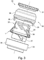
- figure 3 shows a side view of an exploded view of a thread clamping device 30 according to a preferred exemplary embodiment, comprising the loading and unloading device 1 described above with a spring ring element 10 in a stable state.
- the spindles of ring spinning or twisting machines are equipped with thread clamping devices, which are used in the usual way when changing the spinning tubes. That is, the thread clamping device is required when spinning cops of the spindles are completed and must be deducted together upwards from their spindles and replaced with new spinning tubes.
- the thread clamping device 30 shown can be used here.
- the thread clamping device 30 comprises a first clamping element 31 that can be arranged in a stationary manner on an upper spindle part of the spindle, a lower winding sleeve 32 that can also be arranged in a stationary manner on the upper spindle part adjacent to the first clamping element 31, and a second clamping element 33 that can be displaced relative to the lower winding sleeve 32, axially to the longitudinal axis of the lower winding sleeve 32. which is also known as a sliding sleeve.
- the second clamping element 33 is in two parts Lid element 34 and a base element 36 are formed, which can be connected to one another, for example, via a snap-in connection.
- the cover element 34 comprises two projections 35 protruding in the direction of the base element 36, which, in a connected state of the second clamping element 33 with the interposition of the outer holding means 16A, have contact or clamping surface sections 44 (cf. figure 6 ) cooperate to clamp the intermediate outer retaining means 16A.
- the clamping can be done with or without play, if required.
- the cover element 34 and the base element 36 ensure protection of the loading and unloading device 1, together with the centrifugal force elements 20, arranged between the second clamping element 33 and the lower winch sleeve 32.
- the lower winding sleeve 32 is equipped with recesses 37 for respectively receiving one of the inner retaining means 15 of the spring ring element 10, the recesses 37 extending from an underside of the lower winding sleeve 32 via an entrance, a connecting passage at an angle thereto and an end passage running in the circumferential direction of the lower winding sleeve 32 .
- the spring ring element 10 is inserted correspondingly by inserting the inner retaining means 15A, 15B into the entrance, by progressively inserting it into the connecting passage with a slight rotation in the circumferential direction of the under-winding sleeve 32, and by slightly rotating in the circumferential direction of the under-winding sleeve 32 until it reaches the end passage on the under-winding sleeve 32 set, wherein the inner holding means 15A, 15B preferably engage with play in the final gear in order to avoid influencing the spring characteristics.
- the above-described V or L shape of the inner holding means 15A, 15B promotes unimpeded sliding within the recess 37, in particular when the thread clamping device 30 is brought into a cleaning position.
- the underwinding sleeve 32 has a peripheral stop surface section 38 on the outside, on which the centrifugal force element 20 in the figure 3 shown stable state of the spring ring element 20 is present.
- the centrifugal force element 20 is arranged, in particular clamped, between the holding section 18 and the outside stop surface section 38 .
- the stable state of the spring ring element 20 corresponds in a known manner to a closed position of the thread clamping device 30 in which a thread can be reliably fixed.
- the figure 4 shows a side view of an exploded view of the thread clamping device 30 in a metastable state of the loading and unloading device 1 and the spring ring element 10.
- the centrifugal force elements 20 are shown in a position spaced radially from the stop surface 38, with the loading and unloading device 1 or the spring ring element 10 being in the metastable state.
- the centrifugal force elements 20 and the spring ring element 10 assume this position when a spindle comprising the thread clamping device 30 is accelerated to operating speed after a spinning cop change.
- the spring ring element 10 strikes suddenly due to the force of the centrifugal force elements 20 arranged in the receptacles of the spring ring element 10 due to elastic deformation and possibly a cracking noise from the figure 3 shown stable state in the with figure 4 shown metastable state.
- the transition from the stable state to the metastable state results in a relative movement of the outer edge 12, hence the second clamping element 33, to the inner edge 13, consequently to the underwinder sleeve 32 and the first clamping element 31 in a direction away from the first clamping element 31 .
- the second clamping element 33 thereby reaches a metastable position spaced apart from the first clamping element 31 in the sense of "opening the thread clamping device", in which a thread previously clamped between the first clamping element 31 and the second clamping element 33 is released again.
- the spindle speeds decrease continuously and thus also the forces acting on the spring ring element 10 by the centrifugal force elements 20 decrease.
- the spring ring element 10 then jumps back abruptly from the metastable state to the with figure 3 shown stable state.
- the thread clamping device 10 is transferred to a closed state in the sense of "closing the thread clamping device".
- FIG. 5 shows a perspective view from below of the cover element 34 of the second clamping element 33.
- the cover element 34 comprises receiving devices 40 for receiving a centrifugal force element 20 in the metastable state of the spring ring element 10, the receiving device 40 having holding webs 41 which are in the circumferential direction of the cover member 34 for the intermediate arrangement of the centrifugal element 20 opposite to each other. This allows in the Metastable state lateral escape of the centrifugal force element 20 loosely accommodated in the receptacle 18D, 18E in the circumferential direction of the cover element 34 can be prevented.
- the cover element 34 has a head web 42 in a region between the retaining webs 41 to prevent the received centrifugal force element 20 from escaping in the direction of the first clamping element 31 or in a direction opposite to the base element 36 of the second clamping element 33 .
- the centrifugal force element 20 accommodated in the metastable state can thereby be held reliably.
- the cover element 34 comprises further receptacles 43 lying opposite one another on the inside for holding a compensation element 23 in each case in order to avoid a possible deformation caused by centrifugal force.
Landscapes
- Engineering & Computer Science (AREA)
- Mechanical Engineering (AREA)
- Textile Engineering (AREA)
- Spinning Or Twisting Of Yarns (AREA)
Claims (11)
- Dispositif de chargement et de déchargement (1) pour un dispositif de serrage de fil (30) d'une machine à filer ou à retordre montée de manière à permettre une rotation, où le dispositif de chargement et de déchargement (1) comprendune rondelle-ressort concentrique (10) qui peut passer instantanément d'un état stable à un état métastable,un dispositif de retenue interne (15), qui est disposé sur un bord intérieur (13) de la rondelle-ressort concentrique (10) pour le raccordement à une douille d'enroulement (32) fixe de la machine à filer ou à retordre,un dispositif de retenue externe (16), qui est fixé sur un bord extérieur (12) de la rondelle-ressort concentrique (10) pour le raccordement à un élément de serrage (33) de la machine à filer ou à retordre qui peut se déplacer axialement sur l'axe longitudinal de douille d'enroulement (32), par rapport à la douille d'enroulement (32) fixe, etun dispositif de retenue et de guidage (17) pour retenir le guidage des éléments centrifuges (20) entre une position stable et une position métastable, qui peuvent être prises par un mouvement relatif entre les dispositifs de retenue externe (16) et interne (15), la rondelle-ressort concentrique (10) adoptant l'état stable dans la position stable et l'état métastable dans la position métastable,caractérisé en ce quele dispositif de retenue et de guidage (17) présente au moins un logement (18D, 18E) pour un élément centrifuge (20), qui est espacé de la section de la surface annulaire (11) couplée de la rondelle-ressort concentrique (10) raccordant les bords intérieur (13) et extérieur (12) l'un à l'autre.
- Dispositif de chargement et de déchargement (1) selon la revendication 1, caractérisé en ce que le dispositif de retenue interne (15) comporte un élément de retenue transversal en forme de V ou de L pour un engagement particulier avec du jeu dans un évidement (37) correspondant de la douille d'enroulement (32).
- Dispositif de chargement et de déchargement (1) selon la revendication 1 ou 2, caractérisé en ce que le dispositif de retenue interne (15) ou le dispositif de retenue externe (16) comporte deux éléments de retenue (15A, 15B ; 16) qui sont disposés sur des segments annulaires opposés de la rondelle-ressort concentrique (10).
- Dispositif de chargement et de déchargement (1) selon une des revendications précédentes, caractérisé en ce que le logement (18D, 18E) présente une partie de support inférieure (18E) pour l'élément centrifuge (20), opposée à la section de la surface annulaire (11) et espacée de celle-ci, et une partie de support latérale (18D) pour le support de l'élément centrifuge (20) sur un côté de l'élément centrifuge (20) opposé à la douille d'enroulement (32), le logement (18D, 18E) étant en particulier en forme de L transversal.
- Dispositif de chargement et de déchargement (1) selon une des revendications précédentes, caractérisé en ce que le dispositif de retenue et de guidage (17) comporte une partie de support (18B) portant le logement (18D, 18E), s'étendant de façon oblique par rapport à un plan de surface comprenant une section de surface annulaire (11) et disposé sur le bord extérieur (12) ou couplé à celui-ci par une partie de raccord (18A) s'étendant depuis le bord extérieur (12) dans une direction s'éloignant du centre de la rondelle-ressort concentrique.
- Dispositif de chargement et de déchargement (1) selon une des revendications précédentes, caractérisé en ce que le dispositif de chargement et de déchargement (1) comporte des éléments centrifuges (20) en forme de goutte dont l'épaisseur de la zone centrale (21) est différente de celle de la zone latérale (22).
- Dispositif de serrage de fil (30) pour une machine à filer ou à retordre, doté d'un premier élément de serrage (31) pouvant être disposé de manière fixe sur une partie supérieure de la broche de la machine à filer ou à retordre,d'une douille d'enroulement (32) pouvant être disposée de manière fixe sur la partie supérieure de la broche adjacente au premier élément de serrage (31),d'un deuxième élément de serrage (33) pouvant être déplacé manière axiale par rapport à la douille d'enroulement (32), sur l'axe longitudinal de la douille d'enroulement (32),le dispositif de serrage de fil (30) comprenant le dispositif de chargement et de déchargement (1) selon l'une des revendications précédentes, la rondelle-ressort concentrique (10) pouvant passer d'un état stable, dans lequel le deuxième élément de serrage (33) est sollicité par la force du ressort en direction du premier élément de serrage (31), à un état métastable, dans lequel le deuxième élément de serrage (33) est transférable instantanément en raison de la force centrifuge de l'élément centrifuge (20) agissant sur la rondelle-ressort concentrique (10) vers le premier élément de serrage (31), l'élément centrifuge (20) pouvant être disposé de manière mobile entre la douille d'enroulement (32) et le deuxième élément de serrage (33),la douille d'enroulement (32) présentant une partie de surface de butée (38) côté extérieur pour l'élément centrifuge (20) ou pour une partie de logement maintenant l'élément centrifuge (20), contre laquelle l'élément centrifuge (20) ou la partie de logement vient en butée à la suite du transfert par à-coups de la rondelle ressort concentrique (10) dans l'état stable.
- Dispositif de serrage de fil (30) selon la revendication 7, caractérisé en ce que le deuxième élément de serrage (33) présente, sur un côté intérieur opposé à la douille d'enroulement (32), un dispositif de réception (40) destiné au logement de l'élément centrifuge (20) dans l'état métastable de la rondelle-ressort concentrique (10), le dispositif de réception (40) présentant des nervures de retenue (41) qui sont opposées les unes aux autres dans la direction circonférentielle du deuxième élément de serrage (33) pour la disposition intermédiaire de l'élément centrifuge (20).
- Dispositif de serrage de fil (30) selon la revendication 7 ou 8, caractérisé en ce que le deuxième élément de serrage (33) comporte un logement supplémentaire (43) sur l'une des douilles d'enroulement (32) pour la retenue d'un élément de compensation (23) afin d'empêcher une déformation due à la force centrifuge.
- Dispositif de serrage de fil (30) selon les revendications 7 à 9, caractérisé en ce que le deuxième élément de serrage (33) est formé d'un élément de couvercle (34) et d'un élément de base (36) pouvant être relié à un élément de couvercle (34).
- Dispositif de serrage de fil (30) selon les revendications 7 à 10, caractérisé en ce qu'au moins un des éléments de force centrifuge (20) est serré entre un logement (18D, 18E) associé à une rondelle-ressort concentrique (10) pour le logement d'un élément centrifuge (20) et une partie de surface de butée (38) côté extérieur dans état stable du dispositif de serrage de fil (30) au moyen de l'élément de force centrifuge de l'élément centrifuge (10), en particulier au moyen de la force du ressort agissant sur l'élément centrifuge du logement (18D, 18E).
Priority Applications (6)
| Application Number | Priority Date | Filing Date | Title |
|---|---|---|---|
| EP19153746.3A EP3686329B1 (fr) | 2019-01-25 | 2019-01-25 | Dispositif de charge et de décharge pour un dispositif pince-fil et dispositif pince-fil |
| ES19153746T ES2916467T3 (es) | 2019-01-25 | 2019-01-25 | Unidad de carga y descarga para un dispositivo sujetahilo y dispositivo sujetahilo |
| CN202010069067.6A CN111485302B (zh) | 2019-01-25 | 2020-01-21 | 夹纱装置和用于夹纱装置的装卸载机构 |
| TW109102116A TW202035268A (zh) | 2019-01-25 | 2020-01-21 | 紗線夾持之裝置及用於其之裝載與卸載裝置 |
| KR1020200008473A KR102789120B1 (ko) | 2019-01-25 | 2020-01-22 | 실 클램핑 기구용 장착 및 해제 장치와 실 클램핑 기구 |
| JP2020009949A JP7437953B2 (ja) | 2019-01-25 | 2020-01-24 | 糸クランプ装置のための負荷印加兼負荷除去装置および糸クランプ装置 |
Applications Claiming Priority (1)
| Application Number | Priority Date | Filing Date | Title |
|---|---|---|---|
| EP19153746.3A EP3686329B1 (fr) | 2019-01-25 | 2019-01-25 | Dispositif de charge et de décharge pour un dispositif pince-fil et dispositif pince-fil |
Publications (2)
| Publication Number | Publication Date |
|---|---|
| EP3686329A1 EP3686329A1 (fr) | 2020-07-29 |
| EP3686329B1 true EP3686329B1 (fr) | 2022-05-11 |
Family
ID=65236884
Family Applications (1)
| Application Number | Title | Priority Date | Filing Date |
|---|---|---|---|
| EP19153746.3A Active EP3686329B1 (fr) | 2019-01-25 | 2019-01-25 | Dispositif de charge et de décharge pour un dispositif pince-fil et dispositif pince-fil |
Country Status (6)
| Country | Link |
|---|---|
| EP (1) | EP3686329B1 (fr) |
| JP (1) | JP7437953B2 (fr) |
| KR (1) | KR102789120B1 (fr) |
| CN (1) | CN111485302B (fr) |
| ES (1) | ES2916467T3 (fr) |
| TW (1) | TW202035268A (fr) |
Families Citing this family (2)
| Publication number | Priority date | Publication date | Assignee | Title |
|---|---|---|---|---|
| DE102021110888A1 (de) * | 2021-04-28 | 2022-11-03 | Saurer Spinning Solutions Gmbh & Co. Kg | Fadenklemmvorrichtung |
| CN118479308B (zh) * | 2024-07-16 | 2024-09-13 | 常州市君泰化纤制品有限公司 | 一种空变丝自动裁切卷料装置 |
Family Cites Families (8)
| Publication number | Priority date | Publication date | Assignee | Title |
|---|---|---|---|---|
| GB597887A (en) * | 1944-11-30 | 1948-02-05 | British Cotton Ind Res Assoc | Improvements in or relating to doffing apparatus for ring spinning and like frames |
| DE19628826A1 (de) | 1996-07-17 | 1998-01-22 | Lieser Gmbh Beteiligungsgesell | Klemmvorrichtung für Fäden |
| DE102006022484B4 (de) * | 2006-05-13 | 2017-04-27 | Saurer Components Gmbh | Klemmvorrichtung |
| DE102008039502A1 (de) * | 2008-08-23 | 2010-02-25 | Oerlikon Textile Components Gmbh | Klemmvorrichtung |
| DE102008058655B4 (de) | 2008-11-22 | 2019-01-10 | Saurer Spinning Solutions Gmbh & Co. Kg | Klemmvorrichtung |
| DE102011076744A1 (de) | 2011-05-31 | 2012-12-06 | Maschinenfabrik Rieter Ag | Fadenklemmeinrichtung für eine Spinn- oder Zwirnspindel |
| DE102013020470A1 (de) * | 2013-12-03 | 2015-06-03 | Saurer Components Gmbh | Klemmvorrichtung zum Klemmen eines Fadens an einer Spindel einer Spinn- oder Zwirnmaschine und Spinn- oder Zwirnmaschine |
| DE102016007041A1 (de) * | 2016-06-09 | 2017-12-14 | Saurer Components Gmbh | Fadenklemmvorrichtung |
-
2019
- 2019-01-25 ES ES19153746T patent/ES2916467T3/es active Active
- 2019-01-25 EP EP19153746.3A patent/EP3686329B1/fr active Active
-
2020
- 2020-01-21 TW TW109102116A patent/TW202035268A/zh unknown
- 2020-01-21 CN CN202010069067.6A patent/CN111485302B/zh active Active
- 2020-01-22 KR KR1020200008473A patent/KR102789120B1/ko active Active
- 2020-01-24 JP JP2020009949A patent/JP7437953B2/ja active Active
Also Published As
| Publication number | Publication date |
|---|---|
| CN111485302A (zh) | 2020-08-04 |
| EP3686329A1 (fr) | 2020-07-29 |
| JP2020117851A (ja) | 2020-08-06 |
| TW202035268A (zh) | 2020-10-01 |
| ES2916467T3 (es) | 2022-07-01 |
| KR102789120B1 (ko) | 2025-04-01 |
| KR20200093452A (ko) | 2020-08-05 |
| CN111485302B (zh) | 2022-05-17 |
| JP7437953B2 (ja) | 2024-02-26 |
Similar Documents
| Publication | Publication Date | Title |
|---|---|---|
| EP3260406B1 (fr) | Dispositif pince-fil | |
| EP2024265A1 (fr) | Dispositif de serrage | |
| EP3686329B1 (fr) | Dispositif de charge et de décharge pour un dispositif pince-fil et dispositif pince-fil | |
| DE4131134A1 (de) | Drehteller fuer faserbandablageeinrichtungen | |
| EP2157217B1 (fr) | Dispositif de serrage | |
| DE2528485A1 (de) | Aufloesewalze | |
| DE3702276C2 (fr) | ||
| DE4438651A1 (de) | Linearlager für eine starke Belastung | |
| DE10218993A1 (de) | Hülsenteller für einen Spulenrahmen | |
| EP0422413B1 (fr) | Broche avec un palier en deux parties | |
| DE19929582C2 (de) | Spielfreie und zentrierende Hülsenkupplung für die Spindel einer Textilmaschine | |
| DE3004165C2 (fr) | ||
| DE102008008854A1 (de) | Axiallager | |
| DE19755972B4 (de) | Spinnvorrichtung | |
| EP1763599B1 (fr) | Accouplement a douilles active par la force centrifuge | |
| DE3134294C2 (de) | Selbstspannender Hülsenaufnehmer | |
| EP4330453B1 (fr) | Dispositif de serrage de fil | |
| DE102019212290A1 (de) | Radialkolbenpumpe zur Förderung von Kraftstoff | |
| EP0359792A1 (fr) | Bobinoir | |
| WO2024153747A1 (fr) | Élément d'entraînement et dispositif comportant celui-ci pour compacter un ruban sur un métier à filer | |
| DE19653359A1 (de) | Auflösewalze für eine Offenend-Spinnvorrichtung | |
| DE8430471U1 (de) | Aufloesewalze fuer eine offenendspinnvorrichtung | |
| DE1062589B (de) | Oberwalzen-Trag- und -Belastungsarm fuer Spinnereimaschinen-Streckwerke | |
| DD136730B1 (de) | Drahtklemmvorrichtung fuer mehrfachspuler | |
| DE2533291A1 (de) | Vorspinnmaschine |
Legal Events
| Date | Code | Title | Description |
|---|---|---|---|
| PUAI | Public reference made under article 153(3) epc to a published international application that has entered the european phase |
Free format text: ORIGINAL CODE: 0009012 |
|
| STAA | Information on the status of an ep patent application or granted ep patent |
Free format text: STATUS: THE APPLICATION HAS BEEN PUBLISHED |
|
| AK | Designated contracting states |
Kind code of ref document: A1 Designated state(s): AL AT BE BG CH CY CZ DE DK EE ES FI FR GB GR HR HU IE IS IT LI LT LU LV MC MK MT NL NO PL PT RO RS SE SI SK SM TR |
|
| AX | Request for extension of the european patent |
Extension state: BA ME |
|
| STAA | Information on the status of an ep patent application or granted ep patent |
Free format text: STATUS: REQUEST FOR EXAMINATION WAS MADE |
|
| 17P | Request for examination filed |
Effective date: 20210129 |
|
| RBV | Designated contracting states (corrected) |
Designated state(s): AL AT BE BG CH CY CZ DE DK EE ES FI FR GB GR HR HU IE IS IT LI LT LU LV MC MK MT NL NO PL PT RO RS SE SI SK SM TR |
|
| GRAP | Despatch of communication of intention to grant a patent |
Free format text: ORIGINAL CODE: EPIDOSNIGR1 |
|
| RIC1 | Information provided on ipc code assigned before grant |
Ipc: B65H 65/00 20060101ALI20211028BHEP Ipc: D01H 1/38 20060101AFI20211028BHEP |
|
| STAA | Information on the status of an ep patent application or granted ep patent |
Free format text: STATUS: GRANT OF PATENT IS INTENDED |
|
| INTG | Intention to grant announced |
Effective date: 20211202 |
|
| GRAS | Grant fee paid |
Free format text: ORIGINAL CODE: EPIDOSNIGR3 |
|
| GRAA | (expected) grant |
Free format text: ORIGINAL CODE: 0009210 |
|
| STAA | Information on the status of an ep patent application or granted ep patent |
Free format text: STATUS: THE PATENT HAS BEEN GRANTED |
|
| AK | Designated contracting states |
Kind code of ref document: B1 Designated state(s): AL AT BE BG CH CY CZ DE DK EE ES FI FR GB GR HR HU IE IS IT LI LT LU LV MC MK MT NL NO PL PT RO RS SE SI SK SM TR |
|
| REG | Reference to a national code |
Ref country code: GB Ref legal event code: FG4D Free format text: NOT ENGLISH |
|
| REG | Reference to a national code |
Ref country code: CH Ref legal event code: EP |
|
| REG | Reference to a national code |
Ref country code: AT Ref legal event code: REF Ref document number: 1491494 Country of ref document: AT Kind code of ref document: T Effective date: 20220515 |
|
| REG | Reference to a national code |
Ref country code: DE Ref legal event code: R096 Ref document number: 502019004307 Country of ref document: DE |
|
| REG | Reference to a national code |
Ref country code: IE Ref legal event code: FG4D Free format text: LANGUAGE OF EP DOCUMENT: GERMAN |
|
| REG | Reference to a national code |
Ref country code: ES Ref legal event code: FG2A Ref document number: 2916467 Country of ref document: ES Kind code of ref document: T3 Effective date: 20220701 |
|
| REG | Reference to a national code |
Ref country code: LT Ref legal event code: MG9D |
|
| REG | Reference to a national code |
Ref country code: NL Ref legal event code: MP Effective date: 20220511 |
|
| PG25 | Lapsed in a contracting state [announced via postgrant information from national office to epo] |
Ref country code: SE Free format text: LAPSE BECAUSE OF FAILURE TO SUBMIT A TRANSLATION OF THE DESCRIPTION OR TO PAY THE FEE WITHIN THE PRESCRIBED TIME-LIMIT Effective date: 20220511 Ref country code: PT Free format text: LAPSE BECAUSE OF FAILURE TO SUBMIT A TRANSLATION OF THE DESCRIPTION OR TO PAY THE FEE WITHIN THE PRESCRIBED TIME-LIMIT Effective date: 20220912 Ref country code: NO Free format text: LAPSE BECAUSE OF FAILURE TO SUBMIT A TRANSLATION OF THE DESCRIPTION OR TO PAY THE FEE WITHIN THE PRESCRIBED TIME-LIMIT Effective date: 20220811 Ref country code: NL Free format text: LAPSE BECAUSE OF FAILURE TO SUBMIT A TRANSLATION OF THE DESCRIPTION OR TO PAY THE FEE WITHIN THE PRESCRIBED TIME-LIMIT Effective date: 20220511 Ref country code: LT Free format text: LAPSE BECAUSE OF FAILURE TO SUBMIT A TRANSLATION OF THE DESCRIPTION OR TO PAY THE FEE WITHIN THE PRESCRIBED TIME-LIMIT Effective date: 20220511 Ref country code: HR Free format text: LAPSE BECAUSE OF FAILURE TO SUBMIT A TRANSLATION OF THE DESCRIPTION OR TO PAY THE FEE WITHIN THE PRESCRIBED TIME-LIMIT Effective date: 20220511 Ref country code: GR Free format text: LAPSE BECAUSE OF FAILURE TO SUBMIT A TRANSLATION OF THE DESCRIPTION OR TO PAY THE FEE WITHIN THE PRESCRIBED TIME-LIMIT Effective date: 20220812 Ref country code: FI Free format text: LAPSE BECAUSE OF FAILURE TO SUBMIT A TRANSLATION OF THE DESCRIPTION OR TO PAY THE FEE WITHIN THE PRESCRIBED TIME-LIMIT Effective date: 20220511 Ref country code: BG Free format text: LAPSE BECAUSE OF FAILURE TO SUBMIT A TRANSLATION OF THE DESCRIPTION OR TO PAY THE FEE WITHIN THE PRESCRIBED TIME-LIMIT Effective date: 20220811 |
|
| PG25 | Lapsed in a contracting state [announced via postgrant information from national office to epo] |
Ref country code: RS Free format text: LAPSE BECAUSE OF FAILURE TO SUBMIT A TRANSLATION OF THE DESCRIPTION OR TO PAY THE FEE WITHIN THE PRESCRIBED TIME-LIMIT Effective date: 20220511 Ref country code: PL Free format text: LAPSE BECAUSE OF FAILURE TO SUBMIT A TRANSLATION OF THE DESCRIPTION OR TO PAY THE FEE WITHIN THE PRESCRIBED TIME-LIMIT Effective date: 20220511 Ref country code: LV Free format text: LAPSE BECAUSE OF FAILURE TO SUBMIT A TRANSLATION OF THE DESCRIPTION OR TO PAY THE FEE WITHIN THE PRESCRIBED TIME-LIMIT Effective date: 20220511 Ref country code: IS Free format text: LAPSE BECAUSE OF FAILURE TO SUBMIT A TRANSLATION OF THE DESCRIPTION OR TO PAY THE FEE WITHIN THE PRESCRIBED TIME-LIMIT Effective date: 20220911 |
|
| PG25 | Lapsed in a contracting state [announced via postgrant information from national office to epo] |
Ref country code: SM Free format text: LAPSE BECAUSE OF FAILURE TO SUBMIT A TRANSLATION OF THE DESCRIPTION OR TO PAY THE FEE WITHIN THE PRESCRIBED TIME-LIMIT Effective date: 20220511 Ref country code: RO Free format text: LAPSE BECAUSE OF FAILURE TO SUBMIT A TRANSLATION OF THE DESCRIPTION OR TO PAY THE FEE WITHIN THE PRESCRIBED TIME-LIMIT Effective date: 20220511 Ref country code: EE Free format text: LAPSE BECAUSE OF FAILURE TO SUBMIT A TRANSLATION OF THE DESCRIPTION OR TO PAY THE FEE WITHIN THE PRESCRIBED TIME-LIMIT Effective date: 20220511 Ref country code: DK Free format text: LAPSE BECAUSE OF FAILURE TO SUBMIT A TRANSLATION OF THE DESCRIPTION OR TO PAY THE FEE WITHIN THE PRESCRIBED TIME-LIMIT Effective date: 20220511 |
|
| REG | Reference to a national code |
Ref country code: DE Ref legal event code: R097 Ref document number: 502019004307 Country of ref document: DE |
|
| PLBE | No opposition filed within time limit |
Free format text: ORIGINAL CODE: 0009261 |
|
| STAA | Information on the status of an ep patent application or granted ep patent |
Free format text: STATUS: NO OPPOSITION FILED WITHIN TIME LIMIT |
|
| PG25 | Lapsed in a contracting state [announced via postgrant information from national office to epo] |
Ref country code: AL Free format text: LAPSE BECAUSE OF FAILURE TO SUBMIT A TRANSLATION OF THE DESCRIPTION OR TO PAY THE FEE WITHIN THE PRESCRIBED TIME-LIMIT Effective date: 20220511 |
|
| 26N | No opposition filed |
Effective date: 20230214 |
|
| PG25 | Lapsed in a contracting state [announced via postgrant information from national office to epo] |
Ref country code: SI Free format text: LAPSE BECAUSE OF FAILURE TO SUBMIT A TRANSLATION OF THE DESCRIPTION OR TO PAY THE FEE WITHIN THE PRESCRIBED TIME-LIMIT Effective date: 20220511 |
|
| GBPC | Gb: european patent ceased through non-payment of renewal fee |
Effective date: 20230125 |
|
| PG25 | Lapsed in a contracting state [announced via postgrant information from national office to epo] |
Ref country code: LU Free format text: LAPSE BECAUSE OF NON-PAYMENT OF DUE FEES Effective date: 20230125 |
|
| REG | Reference to a national code |
Ref country code: BE Ref legal event code: MM Effective date: 20230131 |
|
| PG25 | Lapsed in a contracting state [announced via postgrant information from national office to epo] |
Ref country code: GB Free format text: LAPSE BECAUSE OF NON-PAYMENT OF DUE FEES Effective date: 20230125 |
|
| PG25 | Lapsed in a contracting state [announced via postgrant information from national office to epo] |
Ref country code: FR Free format text: LAPSE BECAUSE OF NON-PAYMENT OF DUE FEES Effective date: 20230131 Ref country code: BE Free format text: LAPSE BECAUSE OF NON-PAYMENT OF DUE FEES Effective date: 20230131 |
|
| PG25 | Lapsed in a contracting state [announced via postgrant information from national office to epo] |
Ref country code: IE Free format text: LAPSE BECAUSE OF NON-PAYMENT OF DUE FEES Effective date: 20230125 |
|
| PG25 | Lapsed in a contracting state [announced via postgrant information from national office to epo] |
Ref country code: MC Free format text: LAPSE BECAUSE OF FAILURE TO SUBMIT A TRANSLATION OF THE DESCRIPTION OR TO PAY THE FEE WITHIN THE PRESCRIBED TIME-LIMIT Effective date: 20220511 |
|
| PG25 | Lapsed in a contracting state [announced via postgrant information from national office to epo] |
Ref country code: MC Free format text: LAPSE BECAUSE OF FAILURE TO SUBMIT A TRANSLATION OF THE DESCRIPTION OR TO PAY THE FEE WITHIN THE PRESCRIBED TIME-LIMIT Effective date: 20220511 |
|
| PG25 | Lapsed in a contracting state [announced via postgrant information from national office to epo] |
Ref country code: BG Free format text: LAPSE BECAUSE OF FAILURE TO SUBMIT A TRANSLATION OF THE DESCRIPTION OR TO PAY THE FEE WITHIN THE PRESCRIBED TIME-LIMIT Effective date: 20220511 |
|
| PG25 | Lapsed in a contracting state [announced via postgrant information from national office to epo] |
Ref country code: BG Free format text: LAPSE BECAUSE OF FAILURE TO SUBMIT A TRANSLATION OF THE DESCRIPTION OR TO PAY THE FEE WITHIN THE PRESCRIBED TIME-LIMIT Effective date: 20220511 |
|
| REG | Reference to a national code |
Ref country code: AT Ref legal event code: MM01 Ref document number: 1491494 Country of ref document: AT Kind code of ref document: T Effective date: 20240125 |
|
| PG25 | Lapsed in a contracting state [announced via postgrant information from national office to epo] |
Ref country code: AT Free format text: LAPSE BECAUSE OF NON-PAYMENT OF DUE FEES Effective date: 20240125 |
|
| PG25 | Lapsed in a contracting state [announced via postgrant information from national office to epo] |
Ref country code: CY Free format text: LAPSE BECAUSE OF FAILURE TO SUBMIT A TRANSLATION OF THE DESCRIPTION OR TO PAY THE FEE WITHIN THE PRESCRIBED TIME-LIMIT; INVALID AB INITIO Effective date: 20190125 |
|
| PG25 | Lapsed in a contracting state [announced via postgrant information from national office to epo] |
Ref country code: HU Free format text: LAPSE BECAUSE OF FAILURE TO SUBMIT A TRANSLATION OF THE DESCRIPTION OR TO PAY THE FEE WITHIN THE PRESCRIBED TIME-LIMIT; INVALID AB INITIO Effective date: 20190125 |
|
| REG | Reference to a national code |
Ref country code: CH Ref legal event code: U11 Free format text: ST27 STATUS EVENT CODE: U-0-0-U10-U11 (AS PROVIDED BY THE NATIONAL OFFICE) Effective date: 20260201 |
|
| PGFP | Annual fee paid to national office [announced via postgrant information from national office to epo] |
Ref country code: ES Payment date: 20260217 Year of fee payment: 8 |
|
| PGFP | Annual fee paid to national office [announced via postgrant information from national office to epo] |
Ref country code: DE Payment date: 20260120 Year of fee payment: 8 |
|
| PGFP | Annual fee paid to national office [announced via postgrant information from national office to epo] |
Ref country code: AT Payment date: 20260410 Year of fee payment: 5 |
|
| PGFP | Annual fee paid to national office [announced via postgrant information from national office to epo] |
Ref country code: IT Payment date: 20260130 Year of fee payment: 8 |
|
| PGFP | Annual fee paid to national office [announced via postgrant information from national office to epo] |
Ref country code: TR Payment date: 20260119 Year of fee payment: 8 |
|
| PGFP | Annual fee paid to national office [announced via postgrant information from national office to epo] |
Ref country code: CH Payment date: 20260201 Year of fee payment: 8 Ref country code: CZ Payment date: 20260113 Year of fee payment: 8 |
|
| PGFP | Annual fee paid to national office [announced via postgrant information from national office to epo] |
Ref country code: SK Payment date: 20260119 Year of fee payment: 8 |