EP3686409A1 - Elektrische maschinen mit luftspaltsteuersystemen und systeme und verfahren zur steuerung eines luftspalts in einer elektrischen maschine - Google Patents
Elektrische maschinen mit luftspaltsteuersystemen und systeme und verfahren zur steuerung eines luftspalts in einer elektrischen maschine Download PDFInfo
- Publication number
- EP3686409A1 EP3686409A1 EP20150714.2A EP20150714A EP3686409A1 EP 3686409 A1 EP3686409 A1 EP 3686409A1 EP 20150714 A EP20150714 A EP 20150714A EP 3686409 A1 EP3686409 A1 EP 3686409A1
- Authority
- EP
- European Patent Office
- Prior art keywords
- air gap
- temperature
- coolant
- core assembly
- stator core
- Prior art date
- Legal status (The legal status is an assumption and is not a legal conclusion. Google has not performed a legal analysis and makes no representation as to the accuracy of the status listed.)
- Granted
Links
Images


Classifications
-
- H—ELECTRICITY
- H02—GENERATION; CONVERSION OR DISTRIBUTION OF ELECTRIC POWER
- H02K—DYNAMO-ELECTRIC MACHINES
- H02K1/00—Details of the magnetic circuit
- H02K1/04—Details of the magnetic circuit characterised by the material used for insulating the magnetic circuit or parts thereof
-
- H—ELECTRICITY
- H02—GENERATION; CONVERSION OR DISTRIBUTION OF ELECTRIC POWER
- H02P—CONTROL OR REGULATION OF ELECTRIC MOTORS, ELECTRIC GENERATORS OR DYNAMO-ELECTRIC CONVERTERS; CONTROLLING TRANSFORMERS, REACTORS OR CHOKE COILS
- H02P23/00—Arrangements or methods for the control of AC motors characterised by a control method other than vector control
- H02P23/14—Estimation or adaptation of motor parameters, e.g. rotor time constant, flux, speed, current or voltage
-
- H—ELECTRICITY
- H02—GENERATION; CONVERSION OR DISTRIBUTION OF ELECTRIC POWER
- H02K—DYNAMO-ELECTRIC MACHINES
- H02K1/00—Details of the magnetic circuit
- H02K1/06—Details of the magnetic circuit characterised by the shape, form or construction
- H02K1/12—Stationary parts of the magnetic circuit
-
- H—ELECTRICITY
- H02—GENERATION; CONVERSION OR DISTRIBUTION OF ELECTRIC POWER
- H02K—DYNAMO-ELECTRIC MACHINES
- H02K1/00—Details of the magnetic circuit
- H02K1/06—Details of the magnetic circuit characterised by the shape, form or construction
- H02K1/22—Rotating parts of the magnetic circuit
-
- H—ELECTRICITY
- H02—GENERATION; CONVERSION OR DISTRIBUTION OF ELECTRIC POWER
- H02K—DYNAMO-ELECTRIC MACHINES
- H02K11/00—Structural association of dynamo-electric machines with electric components or with devices for shielding, monitoring or protection
- H02K11/20—Structural association of dynamo-electric machines with electric components or with devices for shielding, monitoring or protection for measuring, monitoring, testing, protecting or switching
- H02K11/25—Devices for sensing temperature, or actuated thereby
-
- H—ELECTRICITY
- H02—GENERATION; CONVERSION OR DISTRIBUTION OF ELECTRIC POWER
- H02K—DYNAMO-ELECTRIC MACHINES
- H02K11/00—Structural association of dynamo-electric machines with electric components or with devices for shielding, monitoring or protection
- H02K11/30—Structural association with control circuits or drive circuits
- H02K11/33—Drive circuits, e.g. power electronics
-
- H—ELECTRICITY
- H02—GENERATION; CONVERSION OR DISTRIBUTION OF ELECTRIC POWER
- H02K—DYNAMO-ELECTRIC MACHINES
- H02K9/00—Arrangements for cooling or ventilating
- H02K9/02—Arrangements for cooling or ventilating by ambient air flowing through the machine
- H02K9/04—Arrangements for cooling or ventilating by ambient air flowing through the machine having means for generating a flow of cooling medium
-
- H—ELECTRICITY
- H02—GENERATION; CONVERSION OR DISTRIBUTION OF ELECTRIC POWER
- H02K—DYNAMO-ELECTRIC MACHINES
- H02K9/00—Arrangements for cooling or ventilating
- H02K9/19—Arrangements for cooling or ventilating for machines with closed casing and closed-circuit cooling using a liquid cooling medium, e.g. oil
- H02K9/193—Arrangements for cooling or ventilating for machines with closed casing and closed-circuit cooling using a liquid cooling medium, e.g. oil with provision for replenishing the cooling medium; with means for preventing leakage of the cooling medium
-
- H—ELECTRICITY
- H02—GENERATION; CONVERSION OR DISTRIBUTION OF ELECTRIC POWER
- H02P—CONTROL OR REGULATION OF ELECTRIC MOTORS, ELECTRIC GENERATORS OR DYNAMO-ELECTRIC CONVERTERS; CONTROLLING TRANSFORMERS, REACTORS OR CHOKE COILS
- H02P23/00—Arrangements or methods for the control of AC motors characterised by a control method other than vector control
- H02P23/0004—Control strategies in general, e.g. linear type, e.g. P, PI, PID, using robust control
- H02P23/0018—Control strategies in general, e.g. linear type, e.g. P, PI, PID, using robust control using neural networks
-
- H—ELECTRICITY
- H02—GENERATION; CONVERSION OR DISTRIBUTION OF ELECTRIC POWER
- H02P—CONTROL OR REGULATION OF ELECTRIC MOTORS, ELECTRIC GENERATORS OR DYNAMO-ELECTRIC CONVERTERS; CONTROLLING TRANSFORMERS, REACTORS OR CHOKE COILS
- H02P29/00—Arrangements for regulating or controlling electric motors, appropriate for both AC and DC motors
- H02P29/60—Controlling or determining the temperature of the motor or of the drive
-
- H—ELECTRICITY
- H02—GENERATION; CONVERSION OR DISTRIBUTION OF ELECTRIC POWER
- H02K—DYNAMO-ELECTRIC MACHINES
- H02K2201/00—Specific aspects not provided for in the other groups of this subclass relating to the magnetic circuits
- H02K2201/03—Machines characterised by aspects of the air-gap between rotor and stator
-
- H—ELECTRICITY
- H02—GENERATION; CONVERSION OR DISTRIBUTION OF ELECTRIC POWER
- H02K—DYNAMO-ELECTRIC MACHINES
- H02K2213/00—Specific aspects, not otherwise provided for and not covered by codes H02K2201/00 - H02K2211/00
- H02K2213/09—Machines characterised by the presence of elements which are subject to variation, e.g. adjustable bearings, reconfigurable windings, variable pitch ventilators
Definitions
- the present disclosure relates to electric machines with air gap control systems, and systems and methods of controlling an air gap in an electric machine.
- Electric machines are used in a wide variety of settings, including industrial, commercial, and consumer applications.
- a typical electric machine includes a rotor core assembly and a stator core assembly that circumferentially surrounds the rotor core assembly.
- the space between the inner surface of the stator core and the outer surface of the rotor core assembly is commonly referred to as an "air gap.”
- An air gap of sufficient length is necessary to allow the rotor core assembly to freely rotate without contacting the stator core. While the length of an air gap in an electric machine may depend on the particular electric machine, typically it is desirable to minimize the length L of the air gap because air has a high magnetic reluctance. Additionally, resistive losses in an electric machine each attributable to eddy currents, windage, and hysteresis typically increase as the length L of the air gap increases.
- Electric machines with improved energy efficiency are desired.
- High performance applications typically call for electric machines with a high-power density, meaning that electric machines with increasingly larger power outputs and yet increasingly smaller machine sizes are desired.
- the energy efficiency of an electric machine may be described as a ratio of its useful power output to its total power input, typically expressed as a percentage.
- the difference between the useful power output of an electric machine and its total power output are sometimes referred to as resistive losses. Resistive losses attributable to the air gap in an electric machine are a major contributor to an electric machine's energy efficiency.
- a smaller air gap length can reduce the magnetizing power requirement of the electric machine and thereby improve its energy efficiency.
- Electric machines with an optimized air gap length are desired, as an optimized air gap length can lead to improved performance and energy efficiency.
- Such operating parameters and/or operating conditions may be complexly interrelated and variable depending on how a particular electric machine is actually or uniquely operated.
- the present disclosure embraces methods of controlling a length of an air gap in an electric machine using an air gap controller.
- An exemplary method may include: determining an air gap length value for an electric machine at least in part using an air gap controller, comparing the determined air gap length value to an air gap target value using the air gap controller, and outputting one or more control commands from the air gap controller to one or more controllable devices associated with an air gap control system when the determined air gap length value differs from the air gap target value by a predefined threshold.
- the one or more control commands may be configured to impart a change to one or more operating parameters associated with the air gap control system to adjust a length of an air gap between an outer surface of a rotor core and an inner surface of a stator core of the electric machine.
- the air gap length value may be determined based at least in part on an air gap length model, and the air gap length model may be to utilize one or more model inputs to calculate the air gap length value.
- the one or more controllable devices and/or the one or more operating parameters may be associated with an electric machine and/or an air gap control system.
- an exemplary method of controlling a length of an air gap in an electric machine using an air gap controller may include: receiving at an air gap controller, one or more model inputs comprising data associated with an air gap control system, determining an adjusted air gap target value for an electric machine at least in part using the air gap controller, comparing an air gap length value for the electric machine to the adjusted air gap target value using the air gap controller, and outputting one or more control commands from the air gap controller to one or more controllable devices associated with the air gap control system when the air gap length value differs from the adjusted air gap target value by a predefined threshold.
- the one or more control commands may be configured to impart a change to one or more operating parameters associated with the air gap control system to adjust a length of an air gap between an outer surface of a rotor core and an inner surface of a stator core of the electric machine.
- An exemplary air gap control system may include an electric machine, a coolant circulation system, and an air gap controller.
- An exemplary electric machine may include a rotor core assembly having a rotor core and a rotor shaft operably coupled to the rotor core, and a stator core assembly having a stator core and a stator housing operably coupled to the stator core, with the stator core circumferentially surrounding the rotor core.
- An exemplary electric machine may further include an air gap having a length, L, with the air gap located between and defined by an inner surface of the stator core and an outer surface of the rotor core.
- An exemplary coolant circulation system may include a cooling conduit defining a pathway for circulating coolant through the electric machine and/or an air conduit defining a pathway for supplying cooling air to the electric machine.
- An exemplary air gap controller may be configured to control the length, L of the air gap at least in part by controlling or more of: a temperature of coolant flowing through the cooling conduit, a flow rate of coolant flowing through the cooling conduit, a temperature of cooling air flowing through the air conduit, a power input to the electric machine, and/or a rotor shaft speed of the electric machine.
- the presently disclosed air gap control systems may be implemented in an aircraft, a marine vessel, or a motor vehicle.
- upstream and downstream refer to the relative direction with respect to fluid flow in a fluid pathway.
- upstream refers to the direction from which the fluid flows
- downstream refers to the direction to which the fluid flows.
- top refers to the direction from which the fluid flows
- downstream refers to the direction to which the fluid flows.
- Approximating language is applied to modify any quantitative representation that could permissibly vary without resulting in a change in the basic function to which it is related. Accordingly, a value modified by a term or terms, such as “about”, “approximately”, and “substantially”, are not to be limited to the precise value specified. In at least some instances, the approximating language may correspond to the precision of an instrument for measuring the value, or the precision of the methods or machines for constructing or manufacturing the components and/or systems.
- the present disclosure generally provides electric machines with an air gap control system, and systems and methods of controlling an air gap in an electric machine.
- the length of an air gap may vary because of changing operating parameters and/or operating conditions associated with an electric machine. Additionally, an optimum air gap length may vary depending on the particular operating parameters and/or operating conditions with which an electric machine happens to be operating at any given time. Numerous factors impact both the actual length of the air gap as well as the optimum air gap length. For example, the length of the air gap may vary with centrifugal force of the rotor core assembly, and/or with thermal expansion and contraction of the rotor core assembly, the stator core assembly, and/or various other components of the electric machine.
- the magnetic field in an electric machine may cause the rotor shaft to flex slightly, particularly at regions of the rotor shaft that are furthest from the journals or bearings, etc. that support the rotor shaft. Likewise, these and other factors may affect the optimum air gap length.
- Exemplary air gap control systems may improve the performance and energy efficiency of an electric machine.
- an air gap control system may be configured to control the length of the air gap to optimize for or accommodate different operating parameters and/or operating conditions, or by mitigating or preventing changes to the length of the air gap due to changing operating parameters and/or operating conditions.
- An air gap control system may be configured to optimize for performance and/or energy efficiency with respect to particular operating parameters and/or operating conditions of the electric machine.
- an air gap control system may allow an electric machine to operate with a smaller air gap, thereby enhancing the energy efficiency of the electric machine.
- an air gap control system may mitigate the risk of the rotor contacting the stator, thereby allowing an electric machine to operate with a smaller air gap that otherwise would not be feasible without such an air gap control system in view of acceptable risk tolerance levels.
- Exemplary air gap control systems also may reduce resistive losses attributable to eddy currents, windage, and/or hysteresis by controlling the length of the edge gap.
- an air gap control system may allow an electric machine to operate at higher rotating speeds by opening the air gap to compensate for centrifugal growth.
- An electric machine may function as an electric motor and/or an electric generator.
- An electric motor converts electrical energy into mechanical energy.
- An electric generator converts mechanical energy into electrical energy.
- Some examples where an electric machine may be utilized include aircraft, marine vessels, motor vehicles, power generation facilities, manufacturing facilities, industrial machinery, and the like.
- an electric machine may be used to supply power to a turbomachine engine, such as a turbofan engine in an aircraft.
- the power from the electric machine may be used to start the turbomachine engine, or to provide propulsive thrust to the aircraft, including commercial, military, or civilian aircraft, as well as unmanned aircraft such as unmanned aerial vehicles, electric rotorcraft, drones, and the like.
- an electric machine may be used to supply electrical power to auxiliary systems, including auxiliary systems in an aircraft.
- electric machine may function as both an electric motor and as a generator during different operating states.
- an electric machine may function as an electric motor to start an aircraft engine, and as a generator to supply electric power to systems in the aircraft.
- an electric machine may be used in numerus other settings, and it is intended that the presently disclosed air gap control systems may be implemented in an electric machine in any setting without departing from the scope or spirit of the present disclosure.
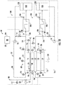
- An exemplary air gap control system 100 includes an electric machine 102, and a coolant circulation system 104. All or a portion of the coolant circulation system 104 may be formed as an integral part of the electric machine 102 or all or a portion of the coolant circulation system 104 may be separate from but in fluid communication with the electric machine 102.
- the electric machine 102 includes a rotor core assembly 106 and a stator core assembly 108.
- the rotor core assembly 106 includes a rotor core 110 and a rotor shaft 112 operably coupled to the rotor core 110.
- the stator core assembly 108 includes a stator core 114 and a stator housing 116 operably coupled to the stator core 114.
- the stator core 114 circumferentially surrounds the rotor core 110.
- the electric machine 102 includes an air gap 118 having a length, L located between and defined by the inner surface 120 of the stator core 114 and the outer surface 122 of the rotor core 110.
- the coolant circulation system 104 may include a cooling conduit 124.
- the cooling conduit 124 defines a pathway for circulating a coolant 126 through the electric machine 102, including the rotor core assembly 106 and/or the stator core assembly 108. At least a portion of the cooling conduit 124 may include structures integrally formed within the electric machine 102. These structures may include one or more of internal or external channels, tubes, pathways, inter-connected or interlaced unit cells, cooling jackets, or the like.
- the cooling conduit 124 may include a rotor core assembly-cooling conduit 128, which includes structures that define a pathway for circulating coolant 126 through or around at least a portion of the rotor core assembly 106, including at least a portion of the rotor core 110 and/or at least a portion of the rotor shaft 112. Additionally, or in the alternative, the cooling conduit 124 may include a stator core assembly-cooling conduit 130, which includes structures that define a pathway for circulating coolant 126 through or around at least a portion of the stator core assembly 108, including at least a portion of the stator core 114 and/or at least a portion of the stator housing 116.
- the rotor core assembly-cooling conduit 128 has a thermally conductive relationship with at least a portion of the rotor core assembly 106, including the rotor core 110 and/or the rotor shaft 112.
- the stator core assembly-cooling conduit 130 has a thermally conductive relationship with at least a portion of the stator core assembly 108, including the stator core 114 and/or the stator housing 116.
- the coolant circulation system 104 may additionally include one or more coolant reservoirs 132, one or more coolant pumps (e.g., a first coolant pump 134 and/or a second coolant pump 136), and one or more heat exchangers 138.
- an air gap control system 100 may include a shared coolant circulation system 104 configured to circulate a shared coolant 126 through a cooling conduit 124 that includes both a rotor core assembly-cooling conduit 128 and a stator core assembly-cooling conduit 130.
- the coolant circulation system 104 shown in FIG. 1A includes a first coolant pump 134 configured to supply coolant 126 to the rotor core assembly 106 via a rotor core assembly-cooling conduit 128, and a second coolant pump 136 configured to supply coolant 126 to the stator core assembly 108 via a stator core assembly-cooling conduit 130.
- the coolant circulation system 104 shown in FIG. 1A additionally includes coolant reservoir 132 and a heat exchanger 138 which are shared between the rotor core assembly-cooling conduit 128 and the stator core assembly-cooling conduit 130.
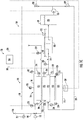
- an air gap control system 100 may include separate coolant circulation systems for the rotor core assembly-cooling conduit 128 and the stator core assembly-cooling conduit 130.
- an air gap control system 100 may include a rotor core coolant circulation system 104A and a stator core coolant circulation system 104B.
- the rotor core coolant circulation system 104A may include a cooling conduit 124A which supplies rotor core coolant 126A circulating through the rotor core assembly 106 to a rotor core heat exchanger 138A.
- Rotor core coolant 126A circulating through the rotor core heat exchanger 138A flows to a rotor core coolant reservoir 132A.
- the first coolant pump 134 supplies rotor core coolant 126A from the rotor core coolant reservoir 132A to the rotor core assembly-cooling conduit 128.
- the stator core coolant circulation system 104B may include a cooling conduit 124B which supplies stator core coolant 126B circulating through the stator core assembly 108 to a stator core heat exchanger 138B.
- Stator core coolant 126B circulating through the stator core heat exchanger 138B flows to a stator core coolant reservoir 132B.
- the second coolant pump 136 supplies stator core coolant 126B from the rotor core coolant reservoir 132A to the stator core assembly-cooling conduit 130.
- a coolant circulation system 104 may include separate pumps for the rotor core assembly-cooling conduit 128 and the stator core assembly-cooling conduit 130.
- a coolant circulation system 104 may include a single common coolant pump 135 configured to supply coolant 126 to both the rotor core assembly 106 via the rotor core assembly-cooling conduit 128 and to the stator core assembly 108 via the stator core assembly-cooling conduit 130.
- the one or more pumps may circulate coolant 126 through the cooling conduit 124.
- Heat generated by the electric machine 102 transfers to the coolant 126 flowing through the cooling conduit 124 (e.g., to coolant 126 flowing through the rotor core assembly-cooling conduit 128 and/or to coolant 126 flowing through the stator core assembly-cooling conduit 130) at a rate that may depend on the temperature gradient between the coolant 126 and the surface of the cooling conduit 124.
- the temperature gradient may depend on, among other things, the temperature of the rotor core assembly 106 and/or of the stator core assembly 108, the supply temperature of the coolant 126, and the flow rate of the coolant 126 through the cooling conduit 124.
- the coolant 126 exits the rotor core assembly-cooling conduit 128 and/or the stator core assembly-cooling conduit 130 having been heated by the thermally conductive relationship therewith.
- the laminations and other various components that make up the rotor core assembly 106 and/or the stator core assembly 108 each have a coefficient of thermal expansion (Y), which describes how the size of the component changes with a change in temperature.
- the coefficient of thermal expansion (Y) may be described with respect to a change in volume, surface area, and/or length with changing temperature.
- the laminations and other various components that make up a rotor core assembly 106 and/or a stator core assembly 108 each have a coefficient of radial thermal expansion (Y r ), which describes how a radial length changes with a change in temperature.
- Heat transferring to the coolant 126 from the rotor core assembly 106 and/or from the stator core assembly 108 may affect the temperature of such laminations or other various components. Accordingly, the size of the laminations or other various components of the rotor core assembly 106 and/or of the stator core assembly 108 may depend on the temperature and/or the flow rate of the coolant 126 flowing through the cooling conduit 124 (e.g., the rotor core assembly-cooling conduit 128 and/or the stator core assembly-cooling conduit 130), since the temperature and or flow rate affects the heat transfer, temperature, and thermal expansion of such components.
- the cooling conduit 124 e.g., the rotor core assembly-cooling conduit 128 and/or the stator core assembly-cooling conduit 130
- the one or more heat exchangers 138 may have any desired configuration suitable to transfer heat from the coolant 126 to the heat sink fluid 140. Suitable heat exchangers include shell and tube, plate and shell, and plate fin configurations, and the like.
- the heat exchanger 138 may be an external component or integrally formed within at least a portion of the electric machine 102.
- the heat sink fluid 140 may be any desired fluid, including a liquid or a gas, or a combination of a liquid and a gas.
- coolant 126 passing through the heat exchanger 138 flows to the coolant reservoir 132, however in some embodiments a coolant reservoir 132 need not be provided.
- the cooling conduit 124 may itself define a coolant reservoir 132.
- the coolant reservoir 132 may be an integral portion of the electric machine 102, or an external component.
- a coolant circulation system 104 may additionally or alternatively utilize a stream of cooling air 146 supplied to the electric machine 102, for example, from an air conduit 148.
- the coolant circulation system 104 may include an air conduit 148 in addition, or as an alternative, to the cooling conduit 124 described herein.
- the air conduit 148 may define a pathway for supplying cooling air 146 to the electric machine 102, such as to a surface of the rotor core assembly 106 and/or a surface of the stator core assembly 108.
- the air conduit 148 may supply a stream of cooling air 146 to the air gap 118.
- a stream of cooling air 146 from the air conduit 148 may flow across the air gap 118, providing cooling to the rotor core assembly 106 and/or the stator core assembly 108.
- the cooling air 146 may flow through the air conduit 148 from an upstream pressure having a higher pressure relative to a downstream pressure.
- the cooling air 146 may include ambient air introduced into the air conduit 148 through an air scoop (not shown) on a nacelle, cowling, housing or the like surrounding the electric motor.
- At least a portion of the air conduit 148 may include structures integrally formed within the electric machine 102. These structures may include one or more of internal or external channels, tubes, pathways, or the like.
- a controllable damper 150 may be provided to control the flow rate of the cooling air 146 flowing through the air conduit 148 and across the air gap 118.
- the controllable damper 150 may be opened at least a portion so as to circulate cooling air 146 through the air conduit 148.
- Heat generated by the electric machine 102 transfers to the cooling air 146 flowing from the air conduit 148 and across the air gap 118 (e.g., from the rotor core 110 to the cooling air 146 flowing across the air gap 118 and/or from the stator core 114 to the cooling air 146 flowing across the air gap 118) at a rate that may depend on the temperature gradient between the cooling air 146 and the surface of the rotor core 110 and/or the surface of the stator core 114.
- the temperature gradient may depend on, among other things, the temperature of the rotor core assembly 106 and/or of the stator core assembly 108, the supply temperature of the cooling air 146, and the flow rate of the cooling air 146 across the air gap 118.
- an exemplary air gap control system 100 includes one or more air gap controllers 200, one or more sensors configured to provide an input 202 to an air gap controller 200, and one or more controllable devices configured to receive an output 204 that includes a control command from an air gap controller 200.
- An exemplary air gap controller 200 may include one or more control models or algorithms that utilize one or more inputs 202 from one or more of the sensors to provide one or more outputs 204 that include a control command to one or more of the controllable devices.
- a single air gap controller 200 may be provided, or a plurality of air gap controllers 200 may be provided. When multiple air gap controllers 200 are provided, each may have responsibility for a different portion of an electric machine 102 and/or for a different purpose of an air gap control system 100.
- An air gap controller 200 may be configured to control the length L of the air gap 118 using a temperature and/or a flow rate of coolant 126 flowing through or around the electric machine 102 (e.g., through the rotor core assembly-cooling conduit 128 and/or the stator core assembly-cooling conduit 130).
- An air gap controller 200 may control the temperature and/or flow rate of the coolant 126, thereby affecting the amount of thermal expansion (Y) in one or more components of the rotor core assembly 106, one or more components of the stator core assembly 108, and/or various other components of the electric machine 102.
- an air gap controller 200 may be configured to control the length L of the air gap 118 using a temperature and/or a flow rate of cooling air 146 flowing across the air gap 118.
- An air gap controller 200 may control the temperature and/or flow rate of the cooling air 146, thereby affecting the amount of thermal expansion (Y) in one or more components of the rotor core assembly 106, one or more components of the stator core assembly 108, and/or various other components of the electric machine 102.
- an air gap controller 200 may be configured, additionally or alternatively, to control the length L of the air gap 118 using a power input and/or rotor shaft speed of the electric machine 102.
- An air gap controller 200 may control a power input to the electric machine 102, thereby affecting the magnetic flux generated by the electric machine 102, and in turn, the heat transfer, temperature, and thermal expansion of various components of the electric machine 102.
- An air gap controller 200 may control a rotor shaft speed of the electric machine 102, thereby affecting the centrifugal force acting upon the rotor core assembly 106.
- Adjustments and/or controls carried out by an air gap controller 200 may change or control the size of the laminations or other various components of the rotor core assembly 106 and/or of the stator core assembly 108 according to their respective coefficient of thermal expansion (Y), thereby adjusting or controlling the length L of the air gap 118.
- Y coefficient of thermal expansion
- adjustments or controls may affect the radial length of the laminations or other various components according to their respective coefficient of radial thermal expansion (Y r ).
- adjustments and/or controls carried out by an air gap controller 200 may control the amount of centrifugal growth and/or flexing of various components of the rotor core assembly 106.
- An air gap controller 200 may be configured to change the length L of the air gap 118 to optimize for or accommodate different operating parameters and/or operating conditions.
- an air gap controller 200 may be configured to control the length L of the air gap 118 to an air gap target value, which air gap target value may vary depending on the particular operating parameters and/or operating conditions. Additionally, or in the alternative, an air gap controller 200 may be configured to prevent or mitigate a change in the length L of the air gap 118.
- such adjustments or controls may prevent or mitigate a change in the size of laminations or other various components of the rotor core assembly 106 and/or of the stator core assembly 108 due to changing operating parameters and/or operating conditions that might otherwise affect the amount of thermal expansion, centrifugal growth, and/or flexing of various components of the electric machine 102.
- the one or more sensors in an exemplary air gap control system 100 may include any sensor capable of ascertaining information pertaining to the air gap control system 100 (e.g., information pertaining to the electric machine 102 and/or the coolant system 104) and capable of providing an input 202 to the air gap controller 200.
- the one or more sensors may include one or more temperature sensors, 206, 208, 210, 212, 214, 216, 217, 219 one or more power sensors 218, 220, one or more rotor speed sensors 222, and/or one or more air gap sensors 224, 226.
- the one or more controllable devices in an exemplary air gap control system 100 may include any device capable of receiving an output 204 that includes a control command from the air gap controller 200.
- the one or more controllable devices may include one or more control valves 228, 230, 232, one or more pumps 134, 136, and/or one or more power control units 234.
- the one or more controllable devices may include one or more control valves 228, 230, 232A, 232B, one or more pumps 134, 136, and/or one or more power control units 234.
- the one or more controllable devices may include one or more control valves 229, 231, 232, one or more pumps 135, and/or one or more power control units 234.
- an air gap controller 200 may determine an air gap length value.
- the air gap length value may be directly measured, sensed, calculated, ascertained, or otherwise determined.
- an air gap controller 200 may determine an air gap length value based at least in part on temperature measurements provided by one or more temperature sensors 206, 208, 210, 212 configured to measure a coolant temperature at one or more locations of the cooling conduit 124 flowing into and out of the rotor core assembly 106 and/or the stator core assembly 108.
- Such coolant temperatures may be used to determine the temperature of the rotor core assembly 106 or various components thereof and/or to determine the temperature of the stator core assembly 108 or various components thereof.
- the length L of the air gap 118 may then be determined based at least in part on these determine temperatures of the rotor core assembly 106 and/or stator core assembly 108 and the respective coefficients of thermal expansion (Y) (e.g., the coefficient of radial thermal expansion (Y r )).
- Y coefficient of thermal expansion
- a first temperature sensor T 1 206 may be configured to ascertain a temperature of coolant 126, 126A flowing into the rotor core assembly 106 and a second temperature sensor T 2 208 may be configured to ascertain a temperature of coolant 126, 126A flowing out of the rotor core assembly 106.
- a rate or quantity of heat transfer from the rotor core assembly 106 to the coolant 126, 126A may be ascertained based at least in part on the difference between the temperature ascertained by the first temperature sensor T 1 206 and the temperature ascertained by the second temperature sensor T 2 208.
- a temperature of the rotor core assembly 106 may be determined based at least in part on a temperature of the coolant 126, 126A, a temperature change in the coolant 126, 126A, and/or rate or quantity of heat transfer to the coolant 126, 126A.
- a third temperature sensor T 3 210 may be configured to ascertain a temperature of coolant 126, 126B flowing into the stator core assembly 108 and a fourth temperature sensor T 4 212 may be configured to ascertain a temperature of coolant 126, 126B flowing out of the stator core assembly 108.
- a rate or quantity of heat transfer from the stator core assembly 108 to the coolant 126, 126B may be ascertained based at least in part on the difference between the temperature ascertained by the third temperature sensor T 3 210 and the temperature ascertained by the fourth temperature sensor T 4 212. Additionally, or in the alternative, a temperature of the stator core assembly 108 (e.g., the stator core 114 and/or the stator housing 116) may be determined based at least in part on a temperature of the coolant 126, 126B, a temperature change in the coolant 126, 126B, and/or rate or quantity of heat transfer to the coolant 126, 126B.
- an air gap controller 200 may determine an air gap length value based at least in part on temperature measurements provide by one or more temperature sensors 214, 216 configured to measure a rotor core assembly temperature and/or a stator core assembly temperature.
- a fifth temperature sensor T 5 214 may be configured to ascertain a temperature of the rotor core assembly 106 and/or a sixth temperature sensor T 6 216 may be configured to ascertain a temperature of the stator core assembly 108.
- the fifth temperature sensor T 5 214 may ascertain a temperature of the rotor core 110 and/or a temperature of the rotor shaft 112.
- multiple temperature sensors may be provided at various locations about the rotor core 110 and/or the rotor shaft 112.
- the sixth temperature sensor T 6 216 may ascertain a temperature of the stator core 114 and/or a temperature of the stator housing 116.
- multiple temperature sensors may be provided at various locations about the stator core 114 and/or the stator housing 116. Any suitable temperature sensors may be used.
- a gap length value may be determined based at least in part on the temperature of the rotor core assembly 106 and/or the temperature of the stator core assembly 108, and the coefficient of thermal expansion (Y) (e.g., the coefficient of radial thermal expansion (Y r )) for the various components thereof.
- Y coefficient of thermal expansion
- an air gap controller 200 may additionally or alternatively determine an air gap length value based at least in part on rotor speed measurements provided by one or more rotor speed sensors 222.
- a rotor core assembly 106 may exhibit centrifugal growth in an amount proportional to the rotational speed of the rotor core assembly 106. Centrifugal force acting upon the rotor core assembly 106 may be ascertained based at least in part on the speed of the rotor core assembly 106. The amount of centrifugal growth exhibited by a rotor core assembly 106 may be determined from such centrifugal force, and an air gap length value may be determined from the amount of centrifugal growth. Accordingly, an air gap controller 200 may be configured to ascertain an air gap length value based at least in part on a correlation between rotor speed and centrifugal growth.
- an air gap controller 200 may additionally or alternatively determine an air gap length value based at least in part on one or more output power measurements provided by one or more power sensors 218, 220.
- the temperature and/or centrifugal growth of a rotor core assembly 106 and/or the temperature of a stator core assembly 108 may be correlated to output power of the electric machine 102.
- the air gap control system 100 may include a first output power sensor 218 configured to measure mechanical output power such as a watt meter, a torque sensor, a speed sensor, or the like.
- the air gap control system 100 may include a second output power sensor 220 configured to measure electrical output power.
- An output power sensor 218, 220 may take the form of a watt meter, a torque sensor, a speed sensor, or the like.
- an air gap controller 200 may additionally or alternatively determine an air gap length value based at least in part on one or more air gap length measurements provided by one or more air gap length sensors 224, 226.
- the air gap length sensors may take the form of a capacitive proximity sensor, or any other suitable distance sensor.
- the air gap length sensors may be non-contact capacitance sensor that generates a signal proportional to an air gap.
- the air gap length sensor may include a capacitive displacement sensor, such as a capaNCDT 6200 sensor available from Micro-Epsilon of Raleigh, North Carolina, USA.
- a plurality of air gap sensors may be positioned at various locations of an electric machine 102 so as to measure an air gap length at such various locations.
- air gap sensors 224, 226 may be positioned at intervals across the longitudinal width and/or radial perimeter of the air gap 118.
- An air gap sensor may be positioned on the stator core assembly 108, as shown with respect to the first air gap sensor 224, and/or on the rotor core assembly 106, as shown with respect to the second air gap sensor 226.
- an air gap control system 100 may include one or more controllable devices.
- an air gap control system 100 may include a rotor core cooling bypass control valve 228 positioned at a rotor core assembly-cooling conduit bypass conduit 142.
- the rotor core cooling bypass control valve 228 may be configured to allow a volume of coolant 126, 126A flowing through the cooling conduit 124 to bypass the heat exchanger 138, 138A, thereby changing the temperature of the coolant 126, 126A flowing through the rotor core assembly-cooling conduit 128.
- the rotor core cooling bypass control valve 228 may be modulated, opened, or closed in response to a control command from the air gap controller 200.
- the rotor core cooling bypass control valve 228 can be opened or modulated in the open-direction to increase the portion of coolant 126, 126A bypassing the heat exchanger 138, thereby changing (e.g., increasing) the temperature of the coolant 126, 126A flowing through the rotor core assembly-cooling conduit 128.
- the rotor core cooling bypass control valve 228 can be closed or modulated in the closed-direction to decrease the portion of coolant 126, 126A bypassing the heat exchanger 138, 138A, thereby changing (e.g., decreasing) the temperature of the coolant 126, 128A flowing through the rotor core assembly-cooling conduit 128.
- an air gap control system 100 may additionally or alternatively include a stator core cooling bypass control valve 230 positioned at a stator core assembly-cooling conduit bypass conduit 144.
- the stator core cooling bypass control valve 230 may be configured to allow a volume of coolant 126, 126B flowing through the cooling conduit 124 to bypass the heat exchanger 138, 138B, thereby changing the temperature of the coolant 126, 126B flowing through the stator core assembly-cooling conduit 130.
- the stator core cooling bypass control valve 230 may be modulated, opened, or closed in response to a control command from the air gap controller 200.
- the stator core cooling bypass control valve 230 may be opened or modulated in the open-direction to increase the portion of coolant 126, 126B bypassing the heat exchanger 138, 138B, thereby increasing the temperature of the coolant 126, 126B flowing through the stator core assembly-cooling conduit 130.
- the stator core cooling bypass control valve 230 can be closed or modulated in the closed-direction to decrease the portion of coolant 126, 126B bypassing the heat exchanger 138, 138B, thereby decreasing the temperature of the coolant 126, 126B flowing through the stator core assembly-cooling conduit 130.
- an air gap control system 100 may include a rotor core cooling control valve 229 positioned at a rotor core assembly-cooling conduit 128 and/or a stator core cooling control valve 231 positioned at a stator core assembly-cooling conduit 130.
- the rotor core cooling control valve 229 may be configured to control the volume of coolant 126 flowing through the rotor core assembly-cooling conduit 128 to the rotor core assembly 106, thereby changing the temperature of the coolant 126 flowing out of the rotor core assembly 106.
- the rotor core cooling control valve 229 may be modulated, opened, or closed in response to a control command from the air gap controller 200.
- the stator core cooling control valve 231 may be configured to control the volume of coolant 126 flowing through the stator core assembly-cooling conduit 130 to the stator core assembly 108, thereby changing the temperature of the coolant 126 flowing out of the stator core assembly 108.
- the stator core cooling control valve 231 may be modulated, opened, or closed in response to a control command from the air gap controller 200.
- the rotor core cooling control valve 229 can be opened or modulated in the open-direction to increase the flow rate of coolant 126 flowing to the rotor core assembly 106, thereby changing (e.g., increasing) the amount of heat transfer between the rotor core assembly 106 and the coolant 126 and changing (e.g., decreasing) the temperature of the coolant 126 flowing out of the rotor core assembly 106.
- the rotor core cooling control valve 229 can be closed or modulated in the closed-direction to decrease the flow rate of coolant 126 flowing to the rotor core assembly 106, thereby changing (e.g., decreasing) the amount of heat transfer between the rotor core assembly 106 and the coolant 126 and changing (e.g., increasing) the temperature of the coolant 126 flowing out of the rotor core assembly 106.
- stator core cooling control valve 231 can be opened or modulated in the open-direction to increase the flow rate of coolant 126 flowing to the stator core assembly 108, thereby changing (e.g., increasing) the amount of heat transfer between the stator core assembly 108 and the coolant 126 and changing (e.g., decreasing) the temperature of the coolant 126 flowing out of the stator core assembly 108.
- the stator core cooling control valve 231 can be closed or modulated in the closed-direction to decrease the flow rate of coolant 126 flowing to the stator core assembly 108, thereby changing (e.g., decreasing) the amount of heat transfer between the stator core assembly 108 and the coolant 126 and changing (e.g., increasing) the temperature of the coolant 126 flowing out of the stator core assembly 108.
- an air gap control system 100 may additionally or alternatively include a stator core cooling bypass control valve 230 positioned at a stator core assembly-cooling conduit bypass conduit 144.
- the stator core cooling bypass control valve 230 may be configured to allow a volume of coolant 126, 126B flowing through the cooling conduit 124 to bypass the heat exchanger 138, 138B, thereby changing the temperature of the coolant 126, 126B flowing through the stator core assembly-cooling conduit 130.
- the stator core cooling bypass control valve 230 may be modulated, opened, or closed in response to a control command from the air gap controller 200.
- the stator core cooling bypass control valve 230 may be opened or modulated in the open-direction to increase the portion of coolant 126, 126B bypassing the heat exchanger 138, 138B, thereby increasing the temperature of the coolant 126, 126B flowing through the stator core assembly-cooling conduit 130.
- the stator core cooling bypass control valve 230 can be closed or modulated in the closed-direction to decrease the portion of coolant 126, 126B bypassing the heat exchanger 138, 138B, thereby decreasing the temperature of the coolant 126, 126B flowing through the stator core assembly-cooling conduit 130.
- an air gap control system 100 may additionally or alternatively include a third control valve 232 configured to start, stop, increase, or decrease a volume of heat sink fluid 140 flowing through or around the heat exchanger 138 in response to a control command from the air gap controller 200, thereby changing the amount of heat transfer with the coolant 126 flowing through the heat exchanger 138, which in turn may change the temperature of the coolant 126 exiting the heat exchanger 138.
- the third control valve 232 may be opened or modulated in the open-direction to increase the volume of heat sink fluid 140 flowing through or around the heat exchanger 138, thereby decreasing the temperature of the coolant 126 exiting the heat exchanger 138.
- the third control valve 232 may be closed or modulated in the closed-direction to decrease the volume of heat sink fluid 140 flowing through or around the heat exchanger 138, thereby increasing the temperature of the coolant 126 exiting the heat exchanger 138.
- the temperature of the coolant 126 may be controlled using the rotor core cooling bypass control valve 228, the stator core cooling bypass control valve 230, and/or the third control valve 232. In some embodiments, the temperature of the coolant 126 may be increased or decreased to change the rate or quantity of heat transfer from the rotor core assembly 106 to the coolant 126 and/or from the stator core assembly 108 to the coolant 126. With a change in the rate or quantity of heat transfer, the size of one or more laminations or other various components of the rotor core assembly 106 or of the stator core assembly 108 may be changed according to their respective coefficient of thermal expansion (Y), thereby adjusting or controlling the length L of the air gap 118.
- Y coefficient of thermal expansion
- an air gap control system 100 may additionally or alternatively include a third control valve 232A configured to start, stop, increase, or decrease a first volume of heat sink fluid 140A flowing through or around the rotor core heat exchanger 138A in response to a control command from the air gap controller 200, thereby changing the amount of heat transfer with the rotor core coolant 126A flowing through the rotor core heat exchanger 138A, which in turn may change the temperature of the rotor core coolant 126A exiting the rotor core heat exchanger 138A.
- a third control valve 232A configured to start, stop, increase, or decrease a first volume of heat sink fluid 140A flowing through or around the rotor core heat exchanger 138A in response to a control command from the air gap controller 200, thereby changing the amount of heat transfer with the rotor core coolant 126A flowing through the rotor core heat exchanger 138A, which in turn may change the temperature of the rotor core coolant 126A exiting the rotor core heat exchanger
- the third control valve 232A may be opened or modulated in the open-direction to increase the first volume of heat sink fluid 140A flowing through or around the rotor core heat exchanger 138A, thereby decreasing the temperature of the rotor core coolant 126A exiting the rotor core heat exchanger 138A.
- the third control valve 232A may be closed or modulated in the closed-direction to decrease the first volume of heat sink fluid 140A flowing through or around the rotor core heat exchanger 138A, thereby increasing the temperature of the rotor core coolant 126A exiting the rotor core heat exchanger 138A.
- the temperature of the rotor core coolant 126A may be controlled using the rotor core cooling bypass control valve 228 and/or the third control valve 232A. In some embodiments, the temperature of rotor core coolant 126A may be increased or decreased to change the rate or quantity of heat transfer from the rotor core assembly 106 to the rotor core coolant 126A. With a change in the rate or quantity of heat transfer, the size of one or more laminations or other various components of the rotor core assembly 106 may be changed according to their respective coefficient of thermal expansion (Y), thereby adjusting or controlling the length L of the air gap 118.
- Y coefficient of thermal expansion
- an air gap control system 100 may additionally or alternatively include a fourth control valve 232B configured to start, stop, increase, or decrease a second volume of heat sink fluid 140B flowing through or around the stator core heat exchanger 138B in response to a control command from the air gap controller 200, thereby changing the amount of heat transfer with the stator core coolant 126B flowing through the stator core heat exchanger 138B, which in turn may change the temperature of the stator core coolant 126B exiting the heat exchanger 138.
- a fourth control valve 232B configured to start, stop, increase, or decrease a second volume of heat sink fluid 140B flowing through or around the stator core heat exchanger 138B in response to a control command from the air gap controller 200, thereby changing the amount of heat transfer with the stator core coolant 126B flowing through the stator core heat exchanger 138B, which in turn may change the temperature of the stator core coolant 126B exiting the heat exchanger 138.
- the fourth control valve 232B may be opened or modulated in the open-direction to increase the second volume of heat sink fluid 140B flowing through or around the stator core heat exchanger 138B, thereby decreasing the temperature of the stator core coolant 126B exiting the stator core heat exchanger 138B.
- the fourth control valve 232B may be closed or modulated in the closed-direction to decrease the second volume of heat sink fluid 140B flowing through or around the stator core heat exchanger 138B, thereby increasing the temperature of the stator core coolant 126B exiting the stator core heat exchanger 138B.
- the temperature of the stator core coolant 126B may be controlled using the stator core cooling bypass control valve 230 and/or the third control valve 232B. In some embodiments, the temperature of the stator core coolant 126B may be increased or decreased to change the rate or quantity of heat transfer from the stator core assembly 108 to the stator core coolant 126B. With a change in the rate or quantity of heat transfer, the size of one or more laminations or other various components of the stator core assembly 108 may be changed according to their respective coefficient of thermal expansion (Y), thereby adjusting or controlling the length L of the air gap 118.
- Y coefficient of thermal expansion
- an air gap control system 100 may include one or more pumps 134, 136 configured to change the flow rate of coolant 126 (or the flow rate of rotor core coolant 126A and/or stator core coolant 126B) flowing through the cooling conduit 124 in response to a control command from the air gap controller 200. As shown in FIGs.
- a first cooling pump 134 may be configured to supply a flow of coolant 126 (or rotor core coolant 126A) through the rotor core assembly-cooling conduit 128, and a second cooling pump 136 may be configured to supply a flow of coolant 126 (or stator core coolant 126B) through the stator core assembly-cooling conduit 130.
- a flow rate of coolant 126 (or rotor core coolant 126A) flowing through the rotor core assembly-cooling conduit 128 may be modulated, started, or stopped using the first coolant pump 134.
- a flow rate of coolant 126 (or stator core coolant 126B) flowing through the stator core assembly-cooling conduit 130 may be modulated, started, or stopped using the second coolant pump 136.
- a flow rate of coolant 126 (or rotor core coolant 126A and/or stator core coolant 126B) flowing through the cooling conduit 124 may be modulated, started, or stopped using a control valve 228, 230.
- the flow rate of coolant 126 may be increased or decreased to change the rate or quantity of heat transfer from the rotor core assembly 106 to the coolant 126 and/or from the stator core assembly 108 to the coolant 126.
- the size of one or more laminations or other various components of the rotor core assembly 106 and/or of the stator core assembly 108 may be changed according to their respective coefficient of thermal expansion (Y), thereby adjusting or controlling the length L of the air gap 118.
- an air gap control system 100 may include one a common coolant pump 135 configured to change the flow rate of coolant 126 flowing through the cooling conduit 124 in response to a control command from the air gap controller 200.
- a common coolant pump 135 may be configured to supply a flow of coolant 126 through both the rotor core assembly-cooling conduit 128 and the stator core assembly-cooling conduit 130.
- the common coolant pump 135 may work in concert with the rotor core cooling control valve 229 229 and the stator core cooling control valve 231.
- a flow rate of coolant 126 flowing through the rotor core assembly-cooling conduit 128 and/or through the stator core assembly-cooling conduit 130 may be modulated, started, or stopped using the common coolant pump 135. Additionally, or alternatively, the proportion of coolant 126 flowing through the rotor core assembly-cooling conduit 128 and the stator core assembly-cooling conduit 130 may be increased or decreased using the rotor core cooling control valve 229 and/or the stator core cooling control valve 231. The flow rate of coolant 126 may be increased or decreased to change the rate or quantity of heat transfer from the rotor core assembly 106 to the coolant 126 and/or from the stator core assembly 108 to the coolant 126.
- the size of one or more laminations or other various components of the rotor core assembly 106 and/or of the stator core assembly 108 may be changed according to their respective coefficient of thermal expansion (Y), thereby adjusting or controlling the length L of the air gap 118.
- an air gap control system 100 may include one or more power control units 234 configured to change a power input or a power output of the electric machine 102 in response to a control command from the air gap controller 200.
- the power control unit 234 may increase or decrease the speed of the rotor shaft 112 and/or the magnetic flux generated by the electric machine 102.
- the power control unit 234 may restrict the permissible rate of change (e.g., acceleration) of the rotor shaft 112.
- An increase or decrease in the power input or power output of the electric machine 102 may change the rate or quantity of heat generation in the rotor core assembly 106 and/or the stator core assembly.
- Such a change in the rate or quantity of heat generation may change the size of one or more laminations or other various components of the rotor core assembly 106 and/or of the stator core assembly 108 according to their respective coefficient of thermal expansion (Y), thereby adjusting or controlling the length L of the air gap 118.
- an increase or decrease in the speed of the rotor shaft 112 may change the amount of centrifugal growth exhibited by a rotor core assembly 106, thereby adjusting or controlling the length L of the air gap 118.
- the air gap control systems 100 shown in FIGs. 1A-1C may be configured to adjust or control the length L of the air gap 118 at least in part by allocating cooling capacity between the rotor core assembly 106 and the stator core assembly 108.
- the length of the air gap 118 may be widened by decreasing the temperature of the coolant 126 flowing to the rotor core assembly 106 and/or increasing the temperature of the coolant flowing to the stator core assembly 108.
- the length of the air gap 118 may be narrowed by increasing the temperature of the coolant 126 flowing to the rotor core assembly 106 and/or decreasing the temperature of the coolant flowing to the stator core assembly 108.
- thermal contraction of the rotor core assembly 106 widens the length L of the air gap 118.
- thermal expansion of the stator core assembly 108 also widens the length L of the air gap 118.
- thermal expansion of the rotor core assembly 106 narrows the length L of the air gap 118; and/or when the temperature of the coolant 126 flowing through the stator core assembly 108 decreases, thermal contraction of the stator core assembly 108 also narrows the length L of the air gap 118.
- the length of the air gap 118 may be increased using the rotor core cooling bypass control valve 228 and/or the stator core cooling bypass control valve 230.
- the length L of the air gap 118 may be widened by increasing the proportion of coolant 126 that bypasses the heat exchanger 138 and returns to the stator core assembly 108 via the stator core assembly-cooling conduit 130 and/or increasing the proportion of coolant that flows through the heat exchanger 138 before returning to the rotor core assembly 106.
- an air gap control system 100 may include a rotor core cooling bypass control valve 228 but not a stator core cooling bypass control valve 230, or a stator core cooling bypass control valve 230 but not a rotor core cooling bypass control valve 228.
- the temperature of the rotor core coolant 126A and the temperature of the stator core coolant 126B can be controlled independently from one another. Additionally, in some embodiments the rotor core coolant 126A and the stator core coolant 126B may include different types of coolant.
- the length of the air gap 118 may be increased using the rotor core cooling control valve 229 and/or the stator core cooling control valve 231.
- the length L of the air gap 118 may be widened by increasing the proportion of coolant 126 that flows to the rotor core assembly 106 via the rotor core assembly-cooling conduit 128 relative to the proportion of coolant 126 that flows to the stator core assembly 108 via the stator core assembly-cooling conduit 130.
- an air gap control system 100 may include a rotor core cooling control valve 229 but not a stator core cooling control valve 231, or a stator core cooling control valve 231but not a rotor core cooling control valve 229.
- an air gap control system 100 may include one or more temperature sensors 217, 218 configured measure a cooling air temperature at one or more locations of the air conduit 148.
- a seventh temperature sensor T 7 217 may be configured to ascertain a temperature of cooling air 146 flowing through an inlet side of the air conduit 148 and an eighth temperature sensor T 8 219 may be configured to ascertain a temperature of cooling air 146 flowing through an outlet side of the air conduit 148.
- a rate or quantity of heat transfer from the rotor core assembly 106 and/or from the stator core assembly 108 to the cooling air 146 may be ascertained based at least in part on the difference between the temperature ascertained by the seventh temperature sensor T 7 217 and the temperature ascertained by the eighth temperature sensor T 8 219.
- An air gap control system 100 may include a controllable damper 150 that may be modulated, opened, or closed in response to a control command from the air gap controller 200.
- the controllable damper 150 may be opened or modulated in the open-direction to increase the portion of cooling air 146 flowing across the air gap, thereby changing the rate of heat transfer between the rotor core 110 and the cooling air 146 and/or between the stator core 114 and the cooling air 146.
- An air gap controller 200 may include one or more computing devices 250, which may be located on or within an electric machine 102, adjacent to an electric machine 102, or at a remote location relative to the electric machine 102.
- the one or more computing devices 250 may include one or more processors 252 and one or more memory devices 254.
- the one or more processors 252 may include any suitable processing device, such as a microprocessor, microcontroller, integrated circuit, logic device, and/or other suitable processing device.
- the one or more memory devices 254 may include one or more computer-readable media, including but not limited to non-transitory computer-readable media, RAM, ROM, hard drives, flash drives, and/or other memory devices.
- the one or more memory device 254 may store information accessible by the one or more processors 252, including computer-readable instructions 256 that can be executed by the one or more processors 252.
- the instructions 256 may be any set of instructions which when executed by the one or more processors 252 cause the one or more processors 252 to perform operations.
- the instructions 256 may be configured to cause the one or more processors 252 to perform operations for which the air gap controller 200 and/or the one or more computing devices 250 are configured. Such operations may include controlling a temperature and/or a flow rate of the coolant 126 flowing through the cooling conduit 124, so as to adjust and/or control the length L of the air gap 118.
- Such operations may additionally or alternatively include controlling a flow rate of cooling air 146 flowing through the air conduit 148 and across the air gap 118, so as to adjust and/or control the length L of the air gap 118.
- the length L of the air gap 118 may be adjusted and/or controlled so as to optimize for or accommodate different operating parameters and/or operating conditions, and/or so as to prevent or mitigate a change in the length L of the air gap 118 as operating parameters or operating conditions change.
- Such operations may include adjusting air gap target values and/or adjusting air gap control models 274 used for determining air gap length targets. Such operations may be carried out according to control commands provided by an air gap control model 274.
- the instructions 256 can be software written in any suitable programming language or can be implemented in hardware. Additionally, and/or alternatively, the instructions 256 can be executed in logically and/or virtually separate threads on processors 252.
- the memory devices 254 may store data 258 accessible by the one or more processors 252.
- the data 258 can include current or real-time data, past data, or a combination thereof.
- the data 258 may be stored in a data library 260.
- the data 258 may include data associated with or generated by an air gap control system 100, including data associated with or generated by an electric machine 102, and/or a coolant circulation system 104 for the electric machine 102, including data 258 associated with or generated by an air gap controller 200, a computing device 250, and/or an air gap control model 274.
- the data 258 may also include other data sets, parameters, outputs, information, etc. shown and/or described herein.
- the past operating data may include an operating history for various operating intervals such as, for example, Operating Interval A, Operating Interval B, Operating Interval C, and so on up to the Nth Operating Interval.
- the past operating data associated with each Operating Interval may include past operating parameters, past operating conditions, past mission management system (MMS) data (e.g., flight management system (FMS) data), and/or past Operating Interval profiles indicative of the nature and conditions of the particular Operating Interval.
- MMS mission management system
- FMS flight management system
- the data 258 may include past mission data (e.g., flight missions, marine missions, land missions) for the electric machine 102 or other similar electric machines stored in a data library 260.
- the past mission data may include a past mission history for one or more various missions such as, for example, Mission A, Mission B, Mission C, and so on up to the Nth Mission.
- the past mission data associated with each Mission may include past operating parameters, past operating conditions, past MMS data (e.g., FMS data), and/or past Mission profiles indicative of the nature and conditions of the particular Mission.
- the operating intervals may be maintenance or service intervals for the electric machine 102 or various components thereof.
- the past operating data may contain a past maintenance or service history for various maintenance or service intervals, such as, for example, Service Interval A, Service Interval B, Service Interval C, and so on up to the Nth Service Interval.
- the maintenance or service intervals may include intervals between any form of maintenance or service typically performed on electric machines.
- the past service data associated with each Service Interval may include past operating parameters, past operating conditions, past MMS data (e.g., FMS data), and/or past Service Interval profiles indicative of the nature and conditions of the particular Service Interval.
- the one or more computing devices 250 may also include a communication interface 262, which may be used for communications with a communications network 264 wired or wireless communication lines 266.
- the communication network 264 may include, for example, a local area network (LAN), a wide area network (WAN), SATCOM network, VHF network, a HF network, a Wi-Fi network, a WiMAX network, a gatelink network, and/or any other suitable communications network for transmitting messages to and/or from the air gap controller 200 across the communication lines 266.
- the communication interface 262 may allow the computing device 250 to communicate with one or more sensors and with one or more controllable devices of an air gap control system 100.
- the communication interface 262 may additionally allow the computing device 250 to communicate with the other components of the electric machine 102 and/or other components of an aircraft, marine vessel, motor vehicle, or facility where the electric machine 102 has been implemented.
- the communication interface 262 may additionally or alternatively allow the computing device 250 to communicate with one or more external resources, such as a server 268 or a data warehouse 270.
- a server 268 or a data warehouse 270 may be configured to transmit data 258 from the data warehouse 270 to the computing device 250, and/or to receive data 268 from the computing device 250 and to store the received data 268 in the data warehouse 270 for further purposes.
- the server 268 and/or the data warehouse 270 may be implemented as part of a mission management system (MMS) 272 such as a flight management system (FMS).
- MMS mission management system
- FMS flight management system
- the communication interface 262 may include any suitable components for interfacing with one or more network(s), including for example, transmitters, receivers, ports, controllers, antennas, and/or other suitable components.
- the communication lines 266 of communication network 264 may include a data bus or a combination of wired and/or wireless communication links.
- an exemplary air gap controller 200 includes one or more air gap control models 274 configured to control the length L of the air gap 118 based at least in part on one or more model inputs, including inputs pertaining to operating parameters and/or operating conditions pertaining to the electric machine 102.
- An exemplary air gap control model 274 may be configured provide a determined air gap length value and compare the determined air gap length value to an air gap target value.
- the air gap control model 274 may output a control command and the air gap controller 200 may transmit an output 204 that includes the control command to one or more controllable devices to adjust the length L of the air gap 118 so as to become closer to the target value.
- the air gap controller 200 may transmit a series of outputs 204 that include one or more control commands to the one or more controllable devices, for example, until the determined length L of the air gap 118 agrees with the air gap target value (e.g., until the determined length L of the air gap 118 differs from the air gap target value by less than a predefined threshold amount).
- the outputs 204 that include the control commands may be routed from the air gap controller 200 to the one or more controllable devices via the communication interface 262.
- Exemplary air gap control models 274 include an Active Air Gap Control (AAGC) model 276 and a High Efficiency Air Gap Control (HEAGC) model 278 as described herein.
- AAGC Active Air Gap Control
- HAGC High Efficiency Air Gap Control
- the exemplary air gap control model 274 shown in FIG. 3 is an AAGC model 276.
- the AAGC model 276 may include an air gap length model 300 and an air gap target model 302.
- the air gap length model 300 receives one or more model inputs 304.
- the air gap length model 300 determines and outputs a determined air gap length value 306.
- the air gap target model 302 receives one or more model inputs 304 and outputs an adjusted air gap target value 328.
- the air gap length model 300 may be based at least in part on a coefficient of thermal expansion for one or more components of a rotor core assembly 106 and/or a stator core assembly 108.
- the coefficient of thermal expansion may include a coefficient of radial thermal expansion for laminations of the rotor core 110 and/or for laminations of the stator core 114.
- the air gap length model 300 additionally or alternatively may be based at least in part on an amount of centrifugal force exhibited by a rotor core assembly 106.
- the determined air gap length value 306 and/or the adjusted air gap target value 328 may depend at least in part on the way the electric machine 102 is currently being operated and/or how the electric machine 102 has been uniquely operated in the past.
- the determined air gap length value 306 and/or the adjusted air gap target value 328 may include one or more values, including a current or real-time value, an average, a maximum, a minimum, and/or a range.
- the determined air gap length value 306 and/or the adjusted air gap target value 328 may additional include one or more statistical parameters, such as a distribution value (e.g., a variance, a standard deviation) and/or a regression coefficient value.
- the AAGC model 276 performs a compare operation 308.
- the compare operation 308 includes one or more operations configured to compare the determined air gap length value 306 to an air gap target value 310.
- the compare operation 308 may include a PID controller or any other suitable controller.
- the compare operation 308 may utilize linear or non-linear control algorithms, and any analytical technique including frequency domain and/or time-domain state space representation techniques.
- the air gap target value 310 may be derived or determined from one or more model inputs 304 and/or from the air gap target model 302. Based on the compare operation 308, the AAGC model 276 provides one or more control commands 312 which may be included in an output 204 from an air gap controller 200.
- the AAGC model 276 provides one or more control commands 312 to adjust the length L of the air gap 118 so as to become closer to the air gap target value 310.
- the one or more control commands 312 may include a command configured to change one or more operating parameters of the electric machine.
- a control command 312 may be configured to adjust a temperature of the coolant 126 and/or a flow rate of the coolant 126 (314), to adjust a flow rate of the cooling air 146 (315), and/or to adjust a power input and/or speed of the rotor shaft 112 (316).
- Such a control command 312 may be effective to adjust a length L of an air gap 118.
- model inputs 304 may be used by an air gap control model 274, including current or real-time data 258, past data 258, or a combination thereof.
- the one or more model inputs 304 may include data 258 associated with or generated by an air gap control system 100, including data 258 associated with or generated by an electric machine 102 and/or a coolant circulation system 104 for the electric machine 102.
- Such data associated with an air gap control system 100 may additionally or alternatively including data 258 associated with or generated by an air gap controller 200, a computing device 250, and/or an air gap control model 274.
- the model inputs 304 may include data 258 associated with, comprising, or generated by an air gap controller 200, data 258 associated with, comprising, or generated by a computing device 250, and/or data associated with, comprising, or generated by an air gap control model 274.
- the model inputs 304 may include data 258 associated with or comprising one or more user inputs 318, data 258 associated with or comprising design specifications 320 for an electric machine102, data 258 associated with or comprising operating parameters 322, data 258 associated with or comprising operating conditions 324, data 258 associated with or comprising mission management system (MMS) data 326, and combinations thereof.
- MMS mission management system
- the model inputs 304 may themselves be regarded as data 258, which may be stored in the data library 260 and/or the data warehouse 270, and which may be included in subsequent model inputs 304.
- the model inputs 304 may additionally include other data sets, parameters, outputs, information, etc. shown and/or described herein.
- Exemplary user inputs 318 may include data 258 associated with or comprising one or more set points for the operation of the electric machine 102, including a power input set point or a power output set point for the electric machine 102, a temperature set point for the coolant 126, a flow rate set point for the coolant 126, a flow rate set point for the cooling air 146, a temperature set point for the rotor core assembly 106 or various components thereof, and a temperature set point for the stator core assembly 108 or various components thereof.
- Exemplary design specifications 320 may include data 258 associated with or comprising a nominal air gap length when the electric machine 102 is at idle or at steady state under certain operating conditions 324, a maximum air gap length, a minimum air gap length, coefficients of thermal expansion (Y) for various components of the electric machine 102, and/or other design information pertaining to the electric machine 102.
- Exemplary operating parameters 322 may include data 258 associated with or comprising parameters associated with the operation of the electric machine 102 and/or the coolant circulation system 104. Such operating parameters 322 may include sensed, measured, determined, or predicted operating speeds, flow rates, power input levels, power output levels, and the like. For example, exemplary operating parameters 322 may include data from one or more sensors, including one or more temperature sensors, 206, 208, 210, 212, 214, 216, 217, 219 one or more power sensors 218, 220, one or more rotor speed sensors 222, one or more air gap sensors 224, 226.
- exemplary operating parameters 322 may include operating states or set points associated with one or more controllable devices, including one or more control valves 228, 230, 232, one or more controllable dampers 150, one or more pumps 134, 136, and/or one or more power control units 234. Any one or more of such operating parameters 322 may be included in a model input 304.
- a model input 304 may include data 258 associated with or comprising one or more coolant temperature inputs, which may be provided by one or more coolant temperature sensors 206, 208, 210, 212, and/or one or more cooling air temperature sensors 217, 219.
- the one or more coolant temperature inputs may include a first temperature input from a first temperature sensor 206 configured to ascertain a temperature of coolant 126 flowing into a rotor core assembly 106, and/or a second temperature input from a second temperature sensor 208 configured to ascertain a temperature of coolant 126 flowing out of the rotor core assembly 106.
- the one or more coolant temperature inputs may include a third temperature input from a third temperature sensor 210 configured to ascertain a temperature of coolant 126 flowing into a stator core assembly 108, and/or a fourth temperature input from a fourth temperature sensor 212 configured to ascertain a temperature of coolant 126 flowing out of the stator core assembly 108.
- a model input 304 may additionally or alternatively include data 258 associated with or comprising one or more rotor core assembly temperature inputs and/or one or more stator core assembly temperature inputs, which may be provided by one or more coolant temperature sensors 214, 216.
- a rotor core assembly temperature input may include a fifth temperature input from a fifth temperature sensor 214 configured to ascertain a temperature of a rotor core assembly 106.
- the temperature of the rotor core assembly 106 may include a temperature of a rotor core 110 and/or a temperature of a rotor shaft 112.
- a stator core assembly temperature input may include a sixth temperature input from a sixth temperature sensor 216 configured to ascertain a temperature of a stator core assembly 108.
- the temperature of the stator core assembly 108 may include a temperature of a stator core 114 and/or a temperature of a stator housing 116.
- a model input 304 may additionally or alternatively include data 258 associated with or comprising one or more cooling air temperature inputs, which may be provided by one or more cooling air temperature sensors 217, 219.
- the one or more cooling air temperature inputs may include a seventh temperature input from a seventh temperature sensor 217 configured to ascertain a temperature of cooling air 146 flowing through an inlet side of the air conduit 148.
- the one or more cooling air temperature inputs may additionally or alternatively include an eighth temperature input from an eighth temperature sensor 219 configured to ascertain a temperature of cooling air 146 flowing through an outlet side of the air conduit 148.
- a model input 304 may additionally or alternatively include data 258 associated with or comprising one or more power sensor inputs provided by one or more power sensors 218, 220, and/or one or more rotor speed inputs provided by one or more rotor speed sensors 222.
- a model input 304 may additionally or alternatively include data 258 associated with or comprising one or more air gap length inputs provided by one or more air gap sensors 224, 226.
- Exemplary operating conditions 324 may include data 258 associated with or comprising operating modes, as well as sensed, measured, calculated, or predicted conditions internal or external to the electric machine 102 which may affect the operation thereof.
- Such internal conditions include temperatures, pressures, heat transfer rates, vibration levels, magnetic flux, etc.
- Such external conditions include ambient temperature, pressure, humidity, wind speed, etc.
- Exemplary MMS data 326 may include data 258 associated with or comprising current, planned, or proposed mission plans.
- the MMS data 326 can include data 258 associated with or comprising current or past missions (e.g., flight missions, marine missions, land missions) for the electric machine 102, including GPS coordinates or waypoints such as the origin and destination and various intermediate GPS coordinates or waypoints, projected path of travel, altitude information, weather information, estimated time in route, as well as various operator inputs.
- the air gap target model 302 may include a machine-learned model 330 that allows the AAGC model 276 to control the length L of the air gap 118 without being explicitly programmed to carry out any particular control protocol.
- the adjusted air gap target value 328 may be applicable for an entire operating period or for a portion of an operating interval, such as all or a portion of a mission, or all or a portion of a service interval.
- the adjusted air gap target value 328 output by the air gap target model 302 e.g., the machine-learned model 330
- the air gap target model 302 may apply to particular altitude or range of altitudes of a flight.
- a machine-learned model 330 may use any suitable machine learning technique, operating regime, or algorithm.
- a machine-learned model 330 may be configured to use pattern recognition, computational learning, artificial intelligence, or the like to derive algorithms that allow the machine-learned model 330 to determine an air gap target value 310.
- a machine-learned model 330 may include an unsupervised or a supervised learning regime, including a semi-supervised learning regime, an active learning regime, a reinforcement learning regime, and/or a representation learning regime.
- a machine-learned model 330 may utilize neural networks, decision trees, association rules, inductive logic algorithms, cluster analysis algorithms, and the like.
- the model inputs 304 may include data 258 associated with or generated by a machine-learned model 330.
- the machine-learned model 330 shown in FIG. 3 includes a neural network.
- an exemplary machine-learned model 330 may include any other suitable model, including a linear discriminant analysis model, a partial least squares discriminant analysis model, a support vector machine model, a random tree model, a logistic regression model, a naive Bayes model, a K-nearest neighbor model, a quadratic discriminant analysis model, an anomaly detection model, a boosted and bagged decision tree model, an artificial neural network model, a C4.5 model, a k-means model, and combinations thereof.
- Even further additional suitable types of machine or statistical learning models are also contemplated.
- the machine-learned model 330 can use certain mathematical methods alone or in combination with one or more machine or statistical learning models.
- the compare operation 308 of an AAGC model 276 may be configured to compare determined air gap length values 306 to an air gap target schedule 310 which may include a series of air gap target values 310 corresponding to different points of an Operating Interval, such as a Mission or a Service Interval.
- the air gap target schedule may be provided by or derived from one or more model inputs 304, and/or an air gap target model 302.
- the machine-learned model 330 may output an adjusted air gap target schedule 328.
- An air gap target schedule 310 or an adjusted air gap target schedule 328 may include air gap target values 310 and/or adjusted air gap target values 328 for all or a portion of an Operating Interval, such as all or a portion of a Mission, or all or a portion of a Service Interval.
- an air gap target schedule or an adjusted air gap target schedule may be provided for all or a portion of a flight mission, including for various flight phases, such as takeoff, climb, cruise, descent, approach and land, missed approach, etc.
- an air gap target schedule or an adjusted air gap target schedule may be provided for all or a portion of a Service Interval, including for various periods between services or maintenance, such as a break-in period, a normal operating period, and a wear-out period.
- an air gap target model 302 may output a confidence score 332, which may provide an indication as to a level of confidence attributable to one or more outputs.
- the confidence score 332 can be used, for example, to set a margin of error to be used by the air gap target model 302 in determining an adjusted air gap target value 328.
- the air gap target model 302 may account for a more conservative or wide margin for error when determining an adjusted air gap target value 328, whereas in the event of a high confidence score 332 the air gap target model 302 may allow for a more aggressive or narrow margin for error when determining an adjusted air gap target value 328.
- the model inputs 304 may include data 258 associated with or comprising a confidence score 332.
- An air gap control model 274 may utilize an operating parameter 322 as a model input 304 to determine an air gap target value 310 based at least in part on such a correlation 400.
- the correlation 400 may be predetermined, for example, based on user input 318 and/or design specifications 320.
- a correlation 400 between an operating parameter 322 and an air gap target value 310 may be provided by an air gap target model 302.
- such a correlation 400 may be provided as a machine-learned output from a machine-learned model 330. As shown in FIG.
- the operating parameter 322 shown in the exemplary correlation 400 is a rotor shaft speed. It will be appreciated, however, that an air gap target value 310 may be correlated with numerous other operating parameters 322, among other model inputs 304, and the example shown in FIG. 4 is not intended to be limiting.
- An air gap control model 274 may utilize a correlation 400 to determine an air gap target value 310.
- the air gap target values 310 provided in the correlation 400 may be selected so that the electric machine 102 can accelerate from any given rotor shaft speed to a maximum continuous speed (e.g., so that a snap acceleration can be performed) without causing the rotor core 110 to contact the stator core 114 and/or without introducing an unacceptable risk that the rotor core 110 might contact the stator core 114.
- a determined air gap length value 306 differs from an air gap target value 310, for example, as determined by a compare operation 308 ( FIG. 3 )
- the air gap control model 274 may provide one or more control commands 312 ( FIG.
- the correlation 400 may include an upper threshold 404 and a lower threshold 406.
- the compare operation 308 may be configured to output a control command 312 only if the determined air gap length value 306 falls outside of the range defined by the upper threshold 404 and the lower threshold 406.
- another exemplary air gap control model 274 may include an HEAGC model 278.
- An HEAGC model 278 may be configured to restrict the acceleration rate of the electric machine 102 and or to increase the length L of the air gap 118 to reduce the risk of the rotor core 110 contacting the stator core 114 during an unexpected or a planned high acceleration event.
- the HEAGC model 278 may be utilized generally, or under various specific operating conditions 324 and/or during various specific stages of a mission such as a flight mission.
- the HEAGC model 278 may be utilized to restrict the acceleration rate of the electric machine 102 so as to reduce the risk of the rotor core 110 contacting the stator core 114 during an unexpected high acceleration event.
- the HEAGC model 278 may disable the restriction on the acceleration rate of the electric machine 102 and correspondingly adjust the air gap target value 310 so as to increase the length L of the air gap 118, thereby reducing the risk of the rotor core 110 contacting the stator core 114 during the expected high acceleration event.
- the HEAGC model 278 can reduce the length L of the air gap 118, and/or once again restrict the rate of acceleration.
- the HEAGC model 278 and its control logic may be used separately or in conjunction with the AAGC model 276.
- the AAGC model 276 can operate to adjust the air gap target value 310 and reduce the length L of the air gap 118 so as to become closer to the air gap target value 310.
- the HEAGC model 278 can be complimentary to the AAGC model 276, but the HEAGC model 278 is not required.
- an exemplary training computing device 500 is shown.
- an air gap target model 302 e.g., a machine-learned model 330
- the training computing device 500 may be communicatively coupled with the air gap controller 200 via the communications network 264 ( FIG. 2 ).
- the training computing device 500 may be included as a part of the air gap controller 200.
- the training computing device 500 may be part of the computing device 250 included as part of the air gap controller 200.
- the training computing device 500 may include one or more processors 502 (e.g., a processor 252) and one or more memory devices 504 (e.g., memory device 254).
- the one or more memory devices 504 can store information accessible by the one or more processors 502, including computer-readable instructions 506 that may be executed by the one or more processors 502.
- the memory devices 504 can further store data 508 that may be accessed by the one or more processors 502.
- the training computing device 500 can also include a communication interface 510 used to communicate with resources on the communication network 264 ( FIG. 2 ).
- the hardware, implementation, and functionality of the components of the training computing device 500 may operate, function, and include the same or similar components as those described with respect to the one or more computing devices 250 of the one or more air gap controllers 200.
- the training computing device 500 includes a model trainer 512 configured to train one or more air gap control models 274, including an air gap length model 300 and/or an air gap target model 302 (e.g., a machine-learned model 330).
- the model trainer 512 may use any one or more various training or learning techniques such as backwards propagation of errors, which may include performing truncated backpropagation through time.
- supervised training techniques may be used on a set of labeled training data.
- the model trainer 512 may perform a number of generalization techniques (e.g., weight decays, dropouts, etc.) to improve the generalization capability of the control model 274 being trained.
- the model trainer 512 can train one or more air gap control models 274 based on a set of training data 514.
- the training data 514 may include past operating data 516, which may include, for example, previous operating parameters 322, previous operating conditions 324, and previous MMS data 326.
- the training data 514 may include at least a portion of the data library 260.
- the data library 260 may include the training data 514 or at least a portion thereof.
- the model trainer 512 may utilize past operating data 516 to train one or more air gap control models 274 how the electric machine 102 has been actually and/or uniquely operated in the past under particular operating conditions 324, such as during a particular Operating Interval, such as a particular Mission or Service Interval. Additionally, or in the alternative, the model trainer 512 may utilize past operating data 516 to validate or test an air gap control model 274, including the determined air gap length model 300 and/or the air gap target model 302 (e.g., the machine-learned model 330).
- a specific subset of training data 514 may be selected when training an air gap control model 274.
- past operating data 516 for one or more particular Missions may be selected from the data library 260 or other memory device.
- the past operating data 516 may be representative of several occurrences of one or more particular Missions.
- the past operating data 516 for Mission A may include mission data for Mission A_1, Mission A_2, and so on to the Nth occurrence of Mission A.
- Such past operating data 516 for Mission A may be utilized by the model trainer 512 to train the air gap target model 302 (e.g., the machine-learned model 330) how the electric machine 102 has been actually and/or uniquely operated over the course of several occurrences of the particular Mission.
- the model trainer 512 can train the machine-learned model 330 so that the machine-learned model 330 is able to machine-learn how the electric machine 102 has been actually and uniquely operated with respect to Mission B, and so on up to Mission N.
- the model trainer 512 may train an air gap control model 274 with respect to any other Operating Interval (e.g., with respect to a Service Interval). Additionally, it will be appreciated that the model trainer 512 can process or pre-process the past operating data 516, for example, to disregard outlier data so that it will not be used to train, test, and/or validate the air gap control model 274. Such outlier data may include outlier occurrences of a particular Mission or other Operating Interval, and/or particular Missions or other Operating Intervals that differ significantly from a group or category of Missions or other Operating Intervals.
- the exemplary method 600 commences with receiving at an air gap controller, one or more model inputs comprising data associated with an air gap control system 100, including data associated with an electric machine and/or data associated with a coolant circulation system 104 for the electric machine 602.
- the data associated with the coolant circulation system 104 may include data associated with a coolant circulation system 104 that provides cooling utilizing a stream of coolant 126 from a cooling conduit 124 and/or a stream of cooling air from an air conduit.
- the exemplary method continues with determining with the air gap controller an air gap length value for the electric machine using an air gap length model 604, and/or determining with the air gap controller an adjusted air gap target value for the electric machine using an air gap target model 606.
- the air gap length model and/or the air gap target model may be configured to utilize the one or more model inputs.
- the air gap length value and/or the adjusted air gap target value may be based at least in part on the one or more model inputs.
- An exemplary method continues by comparing with the air gap controller, an air gap length value to an air gap target value 608.
- the air gap length value may be a pre-existing air gap length value or a determined air gap length value from step 604.
- the air gap target value may be a pre-existing air gap target value, or an adjusted air gap target value determined in step 606.
- the comparison ascertains whether the air gap length value differs from the air gap target value by a predefined threshold.
- the exemplary method continues by outputting with the air gap controller, one or more control commands to one or more controllable devices associated with the air gap control system 100, including one or more controllable devices associated with the electric machine 102 and/or the coolant circulation system 104, when the air gap length value differs from the air gap target value by a predefined threshold 610.
- the one or more control commands are intended to adjust a length L of an air gap 118 between an outer surface of a rotor core 110 and an inner surface of a stator core 114 of an electric machine 102 so as to become closer to the air gap target value.
- the one or more control commands 312 may be configured to impart a change to one or more operating parameters 322 of the electric machine 102 and/or of the coolant circulation system 104 to adjust the length L of an air gap 118.
Landscapes
- Engineering & Computer Science (AREA)
- Power Engineering (AREA)
- Microelectronics & Electronic Packaging (AREA)
- Artificial Intelligence (AREA)
- Evolutionary Computation (AREA)
- Motor Or Generator Cooling System (AREA)
Applications Claiming Priority (1)
| Application Number | Priority Date | Filing Date | Title |
|---|---|---|---|
| US16/257,299 US11329585B2 (en) | 2019-01-25 | 2019-01-25 | Electric machines with air gap control systems, and systems and methods of controlling an air gap in an electric machine |
Publications (2)
| Publication Number | Publication Date |
|---|---|
| EP3686409A1 true EP3686409A1 (de) | 2020-07-29 |
| EP3686409B1 EP3686409B1 (de) | 2022-06-29 |
Family
ID=69147550
Family Applications (1)
| Application Number | Title | Priority Date | Filing Date |
|---|---|---|---|
| EP20150714.2A Active EP3686409B1 (de) | 2019-01-25 | 2020-01-08 | Verfahren zur steuerung eines luftspalts in einer elektrischen maschine und luftspaltsteuersystem |
Country Status (3)
| Country | Link |
|---|---|
| US (2) | US11329585B2 (de) |
| EP (1) | EP3686409B1 (de) |
| CN (1) | CN111490607B (de) |
Cited By (3)
| Publication number | Priority date | Publication date | Assignee | Title |
|---|---|---|---|---|
| CN112390388A (zh) * | 2020-11-25 | 2021-02-23 | 创新奇智(青岛)科技有限公司 | 一种模型训练方法、曝气值预估方法、装置及电子设备 |
| EP4064555A1 (de) * | 2021-03-25 | 2022-09-28 | Wobben Properties GmbH | Windenergieanlage und verfahren zum steuern einer windenergieanlage |
| WO2023218026A1 (de) * | 2022-05-13 | 2023-11-16 | Ebm-Papst Mulfingen Gmbh & Co. Kg | Sensorhalter zum anpressen eines temperatursensors an eine wicklung eines elektromotors |
Families Citing this family (4)
| Publication number | Priority date | Publication date | Assignee | Title |
|---|---|---|---|---|
| CN114977977A (zh) * | 2022-06-13 | 2022-08-30 | 泰酷米中米汽车科技(苏州)有限公司 | 可变气隙马达系统之气隙调变控制方法及装置 |
| CN116094206B (zh) * | 2023-03-08 | 2023-06-23 | 四川宜宾力源电机有限公司 | 一种使用转子的电机及转子与定子的间隙趋势计算方法 |
| CN117767836B (zh) * | 2023-11-28 | 2024-10-11 | 南京金崎新能源动力研究院有限公司 | 一种电机运行集控方法和系统 |
| CN118694091B (zh) * | 2024-06-03 | 2025-04-01 | 中通服咨询设计研究院有限公司 | 一种具有环境感知能力的自适应节能电机装置 |
Citations (5)
| Publication number | Priority date | Publication date | Assignee | Title |
|---|---|---|---|---|
| JP2005318718A (ja) * | 2004-04-28 | 2005-11-10 | Equos Research Co Ltd | アキシャルギャップモータ |
| US20090212728A1 (en) * | 2008-02-21 | 2009-08-27 | Yamaha Hatsudoki Kabushiki Kaisha | Wheel driving apparatus and electric vehicle including the same |
| US20120146445A1 (en) * | 2010-12-13 | 2012-06-14 | Hitachi, Ltd. | Axial Flux Permanent Magnet Brushless Machine |
| US20140339932A1 (en) * | 2013-05-15 | 2014-11-20 | Remy Technologies, L.L.C. | Electric machine including a thermal control module |
| CN108448959A (zh) * | 2018-03-15 | 2018-08-24 | 东南大学 | 一种电机等效气隙模型 |
Family Cites Families (33)
| Publication number | Priority date | Publication date | Assignee | Title |
|---|---|---|---|---|
| US3695944A (en) | 1970-06-17 | 1972-10-03 | Allegheny Ludlum Ind Inc | Iron cobalt vanadium alloy |
| US3892604A (en) | 1972-02-22 | 1975-07-01 | Westinghouse Electric Corp | Method of producing normal grain growth (110) {8 001{9 {0 textured iron-cobalt alloys |
| US3793092A (en) | 1972-11-10 | 1974-02-19 | Gen Electric | Fine-grained, completely decrystallized, annealed cobalt-iron-vanadium articles and method |
| US3977919A (en) | 1973-09-28 | 1976-08-31 | Westinghouse Electric Corporation | Method of producing doubly oriented cobalt iron alloys |
| JPS5320515A (en) * | 1976-08-09 | 1978-02-24 | Hitachi Ltd | Rotor of permanent magnet synchronous motor |
| JPS6051350B2 (ja) * | 1978-01-11 | 1985-11-13 | 株式会社日立製作所 | 同期機の回転子 |
| FR2614073B1 (fr) | 1987-04-15 | 1992-02-14 | Snecma | Dispositif d'ajustement en temps reel du jeu radial entre un rotor et un stator de turbomachine |
| US5126906A (en) * | 1989-04-17 | 1992-06-30 | Hitachi, Ltd. | Rotary magnetic head device with rotary transformer having high coupling coefficient |
| BR9504773A (pt) * | 1995-10-04 | 1997-09-02 | Brasil Compressores Sa | Rotor com imãs permanentes para motor elétrico |
| JP3899668B2 (ja) * | 1998-04-28 | 2007-03-28 | 株式会社デンソー | 界磁巻線式同期機の駆動制御装置 |
| DE19961528C1 (de) | 1999-12-20 | 2001-06-13 | Siemens Ag | Verfahren zur Überwachung des radialen Spalts zwischen dem Rotor und dem Stator eines elektrischen Generators und Vorrichtung zur Durchführung des Verfahrens |
| FR2808806B1 (fr) | 2000-05-12 | 2002-08-30 | Imphy Ugine Precision | Alliage fer-cobalt, notamment pour noyau mobile d'actionneur electromagnetique, et son procede de fabrication |
| US8065022B2 (en) | 2005-09-06 | 2011-11-22 | General Electric Company | Methods and systems for neural network modeling of turbine components |
| US7656135B2 (en) * | 2007-01-05 | 2010-02-02 | General Electric Company | Method and apparatus for controlling rotary machines |
| US8253298B2 (en) * | 2008-07-28 | 2012-08-28 | Direct Drive Systems, Inc. | Slot configuration of an electric machine |
| GB201005270D0 (en) * | 2010-03-30 | 2010-05-12 | Rolls Royce Plc | A method and apparatus for manufacturing a rotor disc |
| KR20130000603A (ko) * | 2011-06-23 | 2013-01-03 | 현대자동차주식회사 | 차량용 구동모터 회전자 및 회전자 내의 영구자석 고정방법 |
| US20140091649A1 (en) * | 2012-10-02 | 2014-04-03 | Remy Technologies, Llc | Electromagnetic interference shield and balance ring for electrical machine |
| GB2501952B (en) * | 2012-10-09 | 2014-03-26 | Integral Powertrain Ltd | A motor and a method of cooling a motor |
| US8912766B2 (en) | 2013-02-08 | 2014-12-16 | General Electric Company | System and method for determining pole shift |
| US9279655B2 (en) * | 2013-02-26 | 2016-03-08 | The United States Of America As Represented By The Secretary Of The Navy | Non-contact electrical machine air gap measurement tool |
| US9373988B2 (en) * | 2013-03-15 | 2016-06-21 | Teco-Westinghouse Motor Company | Assemblies and methods for cooling electric machines |
| JP6140104B2 (ja) | 2014-05-22 | 2017-05-31 | ファナック株式会社 | エアパージ機能を有する電動機 |
| JP6487163B2 (ja) * | 2014-07-31 | 2019-03-20 | 三菱重工サーマルシステムズ株式会社 | ターボ冷凍機 |
| DE102014217858A1 (de) | 2014-09-08 | 2016-03-31 | MTU Aero Engines AG | Oberflächenglättung von generativ hergestellten Bauteilen und entsprechend hergestellte Bauteile einer Strömungsmaschine |
| US10277096B2 (en) * | 2015-11-13 | 2019-04-30 | General Electric Company | System for thermal management in electrical machines |
| US10193421B2 (en) * | 2015-11-13 | 2019-01-29 | General Electric Company | System for thermal management in electrical machines |
| US10344614B2 (en) * | 2016-04-12 | 2019-07-09 | United Technologies Corporation | Active clearance control for a turbine and case |
| EP3249786A1 (de) * | 2016-05-25 | 2017-11-29 | Celeroton AG | Elektromaschine und rotor für eine elektromaschine |
| US9787156B1 (en) * | 2016-08-18 | 2017-10-10 | Rigel Scientific Research Inc. | Energy storage apparatus for storing electrical energy generated by an energy source |
| US10826344B2 (en) * | 2016-11-17 | 2020-11-03 | General Electric Company | High speed electric machine with embedded rotor magnets |
| NL1042205B1 (en) * | 2016-12-30 | 2018-07-23 | Bosch Gmbh Robert | Method for operating a continuously variable transmission incorporating a drive belt in a motor vehicle |
| KR101878677B1 (ko) * | 2017-06-29 | 2018-07-16 | 엘지전자 주식회사 | 전동기의 로터 |
-
2019
- 2019-01-25 US US16/257,299 patent/US11329585B2/en active Active
-
2020
- 2020-01-08 EP EP20150714.2A patent/EP3686409B1/de active Active
- 2020-01-20 CN CN202010065366.2A patent/CN111490607B/zh active Active
-
2022
- 2022-04-06 US US17/714,489 patent/US11962255B2/en active Active
Patent Citations (5)
| Publication number | Priority date | Publication date | Assignee | Title |
|---|---|---|---|---|
| JP2005318718A (ja) * | 2004-04-28 | 2005-11-10 | Equos Research Co Ltd | アキシャルギャップモータ |
| US20090212728A1 (en) * | 2008-02-21 | 2009-08-27 | Yamaha Hatsudoki Kabushiki Kaisha | Wheel driving apparatus and electric vehicle including the same |
| US20120146445A1 (en) * | 2010-12-13 | 2012-06-14 | Hitachi, Ltd. | Axial Flux Permanent Magnet Brushless Machine |
| US20140339932A1 (en) * | 2013-05-15 | 2014-11-20 | Remy Technologies, L.L.C. | Electric machine including a thermal control module |
| CN108448959A (zh) * | 2018-03-15 | 2018-08-24 | 东南大学 | 一种电机等效气隙模型 |
Cited By (5)
| Publication number | Priority date | Publication date | Assignee | Title |
|---|---|---|---|---|
| CN112390388A (zh) * | 2020-11-25 | 2021-02-23 | 创新奇智(青岛)科技有限公司 | 一种模型训练方法、曝气值预估方法、装置及电子设备 |
| CN112390388B (zh) * | 2020-11-25 | 2022-06-14 | 创新奇智(青岛)科技有限公司 | 一种模型训练方法、曝气值预估方法、装置及电子设备 |
| EP4064555A1 (de) * | 2021-03-25 | 2022-09-28 | Wobben Properties GmbH | Windenergieanlage und verfahren zum steuern einer windenergieanlage |
| US11952981B2 (en) | 2021-03-25 | 2024-04-09 | Wobben Properties Gmbh | Wind power installation and method for controlling a wind power installation |
| WO2023218026A1 (de) * | 2022-05-13 | 2023-11-16 | Ebm-Papst Mulfingen Gmbh & Co. Kg | Sensorhalter zum anpressen eines temperatursensors an eine wicklung eines elektromotors |
Also Published As
| Publication number | Publication date |
|---|---|
| US11329585B2 (en) | 2022-05-10 |
| CN111490607A (zh) | 2020-08-04 |
| US20220231625A1 (en) | 2022-07-21 |
| CN111490607B (zh) | 2023-09-05 |
| US20200244202A1 (en) | 2020-07-30 |
| EP3686409B1 (de) | 2022-06-29 |
| US11962255B2 (en) | 2024-04-16 |
Similar Documents
| Publication | Publication Date | Title |
|---|---|---|
| US11962255B2 (en) | Electric machines with air gap control systems, and systems and methods of controlling an air gap in an electric machine | |
| CN114383228B (zh) | 冷却装置系统 | |
| US10414507B2 (en) | Adaptive active clearance control logic | |
| US9133772B2 (en) | Fuel system | |
| EP2853494B1 (de) | Leistungsverwaltungsverfahren und System für ein unbemanntes Luftfahrzeug | |
| EP3242259B1 (de) | Wärmeverwaltungssystemsteuerung und verlängerung der lebensdauer eines wärmetauschers | |
| WO2014149112A1 (en) | Model based distributed health monitoring for aircraft engines | |
| EP2937519B1 (de) | Verfahren zur ansteuerung eines elektrischen startergenerators für gasturbinenmotoren | |
| EP2249004A2 (de) | Verfahren und Vorrichtung zur Regelung der Schubkraft | |
| US20230090415A1 (en) | System and method of detecting an airflow fault condition | |
| CN111720353B (zh) | 用于控制送往气动系统的压缩空气的方法 | |
| EP3640750B1 (de) | Modellprädiktive steuerungssubsystem-leistungsverwaltung | |
| EP3244040B1 (de) | Multivariable treibstoffkontrolle und -schätzer (mfce) zur verhinderung von brennkammerausblasen | |
| CN119543316A (zh) | 一种基于深度强化学习的虚拟电厂动态调控方法 | |
| US12104499B2 (en) | System and method of regulating thermal transport bus pressure | |
| Molana et al. | Analysis and simulation of active surge control in centrifugal compressor based on multiple model controllers: N. Molana et al. | |
| US12366210B2 (en) | Power and thermal management and coordinated control of an integrated system | |
| CN121091926A (zh) | 油冷电机的温度调控系统 | |
| US12252993B1 (en) | Fluid actuator operability improvement with fast energy storage | |
| US12129043B1 (en) | Aircraft heat exchanger bypass flow control with electric motor | |
| CN121849360A (zh) | 一种用于飞机空调的控制方法和系统 | |
| CN121613936A (zh) | 一种垂起固定翼飞行器混合动力协调控制方法及系统 | |
| CN121868751A (zh) | 一种用于高层灭火的无人机控制方法、系统、设备及介质 | |
| BR102021021144B1 (pt) | Sistema e método de calibração de frenagem de veículo |
Legal Events
| Date | Code | Title | Description |
|---|---|---|---|
| PUAI | Public reference made under article 153(3) epc to a published international application that has entered the european phase |
Free format text: ORIGINAL CODE: 0009012 |
|
| STAA | Information on the status of an ep patent application or granted ep patent |
Free format text: STATUS: THE APPLICATION HAS BEEN PUBLISHED |
|
| AK | Designated contracting states |
Kind code of ref document: A1 Designated state(s): AL AT BE BG CH CY CZ DE DK EE ES FI FR GB GR HR HU IE IS IT LI LT LU LV MC MK MT NL NO PL PT RO RS SE SI SK SM TR |
|
| AX | Request for extension of the european patent |
Extension state: BA ME |
|
| STAA | Information on the status of an ep patent application or granted ep patent |
Free format text: STATUS: REQUEST FOR EXAMINATION WAS MADE |
|
| 17P | Request for examination filed |
Effective date: 20210119 |
|
| RBV | Designated contracting states (corrected) |
Designated state(s): AL AT BE BG CH CY CZ DE DK EE ES FI FR GB GR HR HU IE IS IT LI LT LU LV MC MK MT NL NO PL PT RO RS SE SI SK SM TR |
|
| REG | Reference to a national code |
Ref country code: DE Ref legal event code: R079 Ref document number: 602020003697 Country of ref document: DE Free format text: PREVIOUS MAIN CLASS: F01P0011000000 Ipc: H02P0023140000 |
|
| GRAP | Despatch of communication of intention to grant a patent |
Free format text: ORIGINAL CODE: EPIDOSNIGR1 |
|
| STAA | Information on the status of an ep patent application or granted ep patent |
Free format text: STATUS: GRANT OF PATENT IS INTENDED |
|
| RIC1 | Information provided on ipc code assigned before grant |
Ipc: H02P 31/00 20060101AFI20211006BHEP |
|
| INTG | Intention to grant announced |
Effective date: 20211021 |
|
| RIC1 | Information provided on ipc code assigned before grant |
Ipc: H02P 29/60 20160101ALI20211011BHEP Ipc: H02P 23/00 20160101ALI20211011BHEP Ipc: H02P 23/14 20060101AFI20211011BHEP |
|
| GRAJ | Information related to disapproval of communication of intention to grant by the applicant or resumption of examination proceedings by the epo deleted |
Free format text: ORIGINAL CODE: EPIDOSDIGR1 |
|
| STAA | Information on the status of an ep patent application or granted ep patent |
Free format text: STATUS: REQUEST FOR EXAMINATION WAS MADE |
|
| GRAP | Despatch of communication of intention to grant a patent |
Free format text: ORIGINAL CODE: EPIDOSNIGR1 |
|
| STAA | Information on the status of an ep patent application or granted ep patent |
Free format text: STATUS: GRANT OF PATENT IS INTENDED |
|
| INTG | Intention to grant announced |
Effective date: 20220127 |
|
| GRAS | Grant fee paid |
Free format text: ORIGINAL CODE: EPIDOSNIGR3 |
|
| GRAA | (expected) grant |
Free format text: ORIGINAL CODE: 0009210 |
|
| STAA | Information on the status of an ep patent application or granted ep patent |
Free format text: STATUS: THE PATENT HAS BEEN GRANTED |
|
| AK | Designated contracting states |
Kind code of ref document: B1 Designated state(s): AL AT BE BG CH CY CZ DE DK EE ES FI FR GB GR HR HU IE IS IT LI LT LU LV MC MK MT NL NO PL PT RO RS SE SI SK SM TR |
|
| REG | Reference to a national code |
Ref country code: CH Ref legal event code: EP |
|
| REG | Reference to a national code |
Ref country code: AT Ref legal event code: REF Ref document number: 1501997 Country of ref document: AT Kind code of ref document: T Effective date: 20220715 |
|
| REG | Reference to a national code |
Ref country code: IE Ref legal event code: FG4D |
|
| REG | Reference to a national code |
Ref country code: DE Ref legal event code: R096 Ref document number: 602020003697 Country of ref document: DE |
|
| REG | Reference to a national code |
Ref country code: LT Ref legal event code: MG9D |
|
| PG25 | Lapsed in a contracting state [announced via postgrant information from national office to epo] |
Ref country code: SE Free format text: LAPSE BECAUSE OF FAILURE TO SUBMIT A TRANSLATION OF THE DESCRIPTION OR TO PAY THE FEE WITHIN THE PRESCRIBED TIME-LIMIT Effective date: 20220629 Ref country code: NO Free format text: LAPSE BECAUSE OF FAILURE TO SUBMIT A TRANSLATION OF THE DESCRIPTION OR TO PAY THE FEE WITHIN THE PRESCRIBED TIME-LIMIT Effective date: 20220929 Ref country code: LT Free format text: LAPSE BECAUSE OF FAILURE TO SUBMIT A TRANSLATION OF THE DESCRIPTION OR TO PAY THE FEE WITHIN THE PRESCRIBED TIME-LIMIT Effective date: 20220629 Ref country code: HR Free format text: LAPSE BECAUSE OF FAILURE TO SUBMIT A TRANSLATION OF THE DESCRIPTION OR TO PAY THE FEE WITHIN THE PRESCRIBED TIME-LIMIT Effective date: 20220629 Ref country code: GR Free format text: LAPSE BECAUSE OF FAILURE TO SUBMIT A TRANSLATION OF THE DESCRIPTION OR TO PAY THE FEE WITHIN THE PRESCRIBED TIME-LIMIT Effective date: 20220930 Ref country code: FI Free format text: LAPSE BECAUSE OF FAILURE TO SUBMIT A TRANSLATION OF THE DESCRIPTION OR TO PAY THE FEE WITHIN THE PRESCRIBED TIME-LIMIT Effective date: 20220629 Ref country code: BG Free format text: LAPSE BECAUSE OF FAILURE TO SUBMIT A TRANSLATION OF THE DESCRIPTION OR TO PAY THE FEE WITHIN THE PRESCRIBED TIME-LIMIT Effective date: 20220929 |
|
| REG | Reference to a national code |
Ref country code: NL Ref legal event code: MP Effective date: 20220629 |
|
| REG | Reference to a national code |
Ref country code: AT Ref legal event code: MK05 Ref document number: 1501997 Country of ref document: AT Kind code of ref document: T Effective date: 20220629 |
|
| PG25 | Lapsed in a contracting state [announced via postgrant information from national office to epo] |
Ref country code: RS Free format text: LAPSE BECAUSE OF FAILURE TO SUBMIT A TRANSLATION OF THE DESCRIPTION OR TO PAY THE FEE WITHIN THE PRESCRIBED TIME-LIMIT Effective date: 20220629 Ref country code: LV Free format text: LAPSE BECAUSE OF FAILURE TO SUBMIT A TRANSLATION OF THE DESCRIPTION OR TO PAY THE FEE WITHIN THE PRESCRIBED TIME-LIMIT Effective date: 20220629 |
|
| PG25 | Lapsed in a contracting state [announced via postgrant information from national office to epo] |
Ref country code: NL Free format text: LAPSE BECAUSE OF FAILURE TO SUBMIT A TRANSLATION OF THE DESCRIPTION OR TO PAY THE FEE WITHIN THE PRESCRIBED TIME-LIMIT Effective date: 20220629 |
|
| PG25 | Lapsed in a contracting state [announced via postgrant information from national office to epo] |
Ref country code: SM Free format text: LAPSE BECAUSE OF FAILURE TO SUBMIT A TRANSLATION OF THE DESCRIPTION OR TO PAY THE FEE WITHIN THE PRESCRIBED TIME-LIMIT Effective date: 20220629 Ref country code: SK Free format text: LAPSE BECAUSE OF FAILURE TO SUBMIT A TRANSLATION OF THE DESCRIPTION OR TO PAY THE FEE WITHIN THE PRESCRIBED TIME-LIMIT Effective date: 20220629 Ref country code: RO Free format text: LAPSE BECAUSE OF FAILURE TO SUBMIT A TRANSLATION OF THE DESCRIPTION OR TO PAY THE FEE WITHIN THE PRESCRIBED TIME-LIMIT Effective date: 20220629 Ref country code: PT Free format text: LAPSE BECAUSE OF FAILURE TO SUBMIT A TRANSLATION OF THE DESCRIPTION OR TO PAY THE FEE WITHIN THE PRESCRIBED TIME-LIMIT Effective date: 20221031 Ref country code: ES Free format text: LAPSE BECAUSE OF FAILURE TO SUBMIT A TRANSLATION OF THE DESCRIPTION OR TO PAY THE FEE WITHIN THE PRESCRIBED TIME-LIMIT Effective date: 20220629 Ref country code: EE Free format text: LAPSE BECAUSE OF FAILURE TO SUBMIT A TRANSLATION OF THE DESCRIPTION OR TO PAY THE FEE WITHIN THE PRESCRIBED TIME-LIMIT Effective date: 20220629 Ref country code: AT Free format text: LAPSE BECAUSE OF FAILURE TO SUBMIT A TRANSLATION OF THE DESCRIPTION OR TO PAY THE FEE WITHIN THE PRESCRIBED TIME-LIMIT Effective date: 20220629 |
|
| PG25 | Lapsed in a contracting state [announced via postgrant information from national office to epo] |
Ref country code: PL Free format text: LAPSE BECAUSE OF FAILURE TO SUBMIT A TRANSLATION OF THE DESCRIPTION OR TO PAY THE FEE WITHIN THE PRESCRIBED TIME-LIMIT Effective date: 20220629 Ref country code: IS Free format text: LAPSE BECAUSE OF FAILURE TO SUBMIT A TRANSLATION OF THE DESCRIPTION OR TO PAY THE FEE WITHIN THE PRESCRIBED TIME-LIMIT Effective date: 20221029 |
|
| REG | Reference to a national code |
Ref country code: DE Ref legal event code: R097 Ref document number: 602020003697 Country of ref document: DE |
|
| PG25 | Lapsed in a contracting state [announced via postgrant information from national office to epo] |
Ref country code: AL Free format text: LAPSE BECAUSE OF FAILURE TO SUBMIT A TRANSLATION OF THE DESCRIPTION OR TO PAY THE FEE WITHIN THE PRESCRIBED TIME-LIMIT Effective date: 20220629 |
|
| PG25 | Lapsed in a contracting state [announced via postgrant information from national office to epo] |
Ref country code: DK Free format text: LAPSE BECAUSE OF FAILURE TO SUBMIT A TRANSLATION OF THE DESCRIPTION OR TO PAY THE FEE WITHIN THE PRESCRIBED TIME-LIMIT Effective date: 20220629 Ref country code: CZ Free format text: LAPSE BECAUSE OF FAILURE TO SUBMIT A TRANSLATION OF THE DESCRIPTION OR TO PAY THE FEE WITHIN THE PRESCRIBED TIME-LIMIT Effective date: 20220629 |
|
| PLBE | No opposition filed within time limit |
Free format text: ORIGINAL CODE: 0009261 |
|
| STAA | Information on the status of an ep patent application or granted ep patent |
Free format text: STATUS: NO OPPOSITION FILED WITHIN TIME LIMIT |
|
| 26N | No opposition filed |
Effective date: 20230330 |
|
| P01 | Opt-out of the competence of the unified patent court (upc) registered |
Effective date: 20230411 |
|
| PG25 | Lapsed in a contracting state [announced via postgrant information from national office to epo] |
Ref country code: SI Free format text: LAPSE BECAUSE OF FAILURE TO SUBMIT A TRANSLATION OF THE DESCRIPTION OR TO PAY THE FEE WITHIN THE PRESCRIBED TIME-LIMIT Effective date: 20220629 |
|
| REG | Reference to a national code |
Ref country code: CH Ref legal event code: PL |
|
| PG25 | Lapsed in a contracting state [announced via postgrant information from national office to epo] |
Ref country code: LU Free format text: LAPSE BECAUSE OF NON-PAYMENT OF DUE FEES Effective date: 20230108 |
|
| REG | Reference to a national code |
Ref country code: BE Ref legal event code: MM Effective date: 20230131 |
|
| PG25 | Lapsed in a contracting state [announced via postgrant information from national office to epo] |
Ref country code: LI Free format text: LAPSE BECAUSE OF NON-PAYMENT OF DUE FEES Effective date: 20230131 Ref country code: CH Free format text: LAPSE BECAUSE OF NON-PAYMENT OF DUE FEES Effective date: 20230131 |
|
| PG25 | Lapsed in a contracting state [announced via postgrant information from national office to epo] |
Ref country code: BE Free format text: LAPSE BECAUSE OF NON-PAYMENT OF DUE FEES Effective date: 20230131 |
|
| PG25 | Lapsed in a contracting state [announced via postgrant information from national office to epo] |
Ref country code: IT Free format text: LAPSE BECAUSE OF FAILURE TO SUBMIT A TRANSLATION OF THE DESCRIPTION OR TO PAY THE FEE WITHIN THE PRESCRIBED TIME-LIMIT Effective date: 20220629 Ref country code: IE Free format text: LAPSE BECAUSE OF NON-PAYMENT OF DUE FEES Effective date: 20230108 |
|
| PG25 | Lapsed in a contracting state [announced via postgrant information from national office to epo] |
Ref country code: MC Free format text: LAPSE BECAUSE OF FAILURE TO SUBMIT A TRANSLATION OF THE DESCRIPTION OR TO PAY THE FEE WITHIN THE PRESCRIBED TIME-LIMIT Effective date: 20220629 |
|
| PG25 | Lapsed in a contracting state [announced via postgrant information from national office to epo] |
Ref country code: MC Free format text: LAPSE BECAUSE OF FAILURE TO SUBMIT A TRANSLATION OF THE DESCRIPTION OR TO PAY THE FEE WITHIN THE PRESCRIBED TIME-LIMIT Effective date: 20220629 |
|
| PG25 | Lapsed in a contracting state [announced via postgrant information from national office to epo] |
Ref country code: BG Free format text: LAPSE BECAUSE OF FAILURE TO SUBMIT A TRANSLATION OF THE DESCRIPTION OR TO PAY THE FEE WITHIN THE PRESCRIBED TIME-LIMIT Effective date: 20220629 |
|
| PG25 | Lapsed in a contracting state [announced via postgrant information from national office to epo] |
Ref country code: BG Free format text: LAPSE BECAUSE OF FAILURE TO SUBMIT A TRANSLATION OF THE DESCRIPTION OR TO PAY THE FEE WITHIN THE PRESCRIBED TIME-LIMIT Effective date: 20220629 |
|
| PG25 | Lapsed in a contracting state [announced via postgrant information from national office to epo] |
Ref country code: CY Free format text: LAPSE BECAUSE OF FAILURE TO SUBMIT A TRANSLATION OF THE DESCRIPTION OR TO PAY THE FEE WITHIN THE PRESCRIBED TIME-LIMIT; INVALID AB INITIO Effective date: 20200108 |
|
| PG25 | Lapsed in a contracting state [announced via postgrant information from national office to epo] |
Ref country code: HU Free format text: LAPSE BECAUSE OF FAILURE TO SUBMIT A TRANSLATION OF THE DESCRIPTION OR TO PAY THE FEE WITHIN THE PRESCRIBED TIME-LIMIT; INVALID AB INITIO Effective date: 20200108 |
|
| PG25 | Lapsed in a contracting state [announced via postgrant information from national office to epo] |
Ref country code: TR Free format text: LAPSE BECAUSE OF FAILURE TO SUBMIT A TRANSLATION OF THE DESCRIPTION OR TO PAY THE FEE WITHIN THE PRESCRIBED TIME-LIMIT Effective date: 20220629 |
|
| PGFP | Annual fee paid to national office [announced via postgrant information from national office to epo] |
Ref country code: GB Payment date: 20251220 Year of fee payment: 7 |
|
| PGFP | Annual fee paid to national office [announced via postgrant information from national office to epo] |
Ref country code: FR Payment date: 20251217 Year of fee payment: 7 |
|
| PGFP | Annual fee paid to national office [announced via postgrant information from national office to epo] |
Ref country code: DE Payment date: 20251217 Year of fee payment: 7 |