EP3686437B1 - Laufrad und drehmaschine - Google Patents
Laufrad und drehmaschine Download PDFInfo
- Publication number
- EP3686437B1 EP3686437B1 EP18882965.9A EP18882965A EP3686437B1 EP 3686437 B1 EP3686437 B1 EP 3686437B1 EP 18882965 A EP18882965 A EP 18882965A EP 3686437 B1 EP3686437 B1 EP 3686437B1
- Authority
- EP
- European Patent Office
- Prior art keywords
- axis
- groove
- insertion portion
- disk member
- peripheral surface
- Prior art date
- Legal status (The legal status is an assumption and is not a legal conclusion. Google has not performed a legal analysis and makes no representation as to the accuracy of the status listed.)
- Active
Links
- 238000003780 insertion Methods 0.000 claims description 117
- 230000037431 insertion Effects 0.000 claims description 117
- 230000002093 peripheral effect Effects 0.000 claims description 103
- 238000009751 slip forming Methods 0.000 description 8
- 239000012530 fluid Substances 0.000 description 5
- 238000009826 distribution Methods 0.000 description 4
- 238000012986 modification Methods 0.000 description 3
- 230000004048 modification Effects 0.000 description 3
- 238000003754 machining Methods 0.000 description 2
- 238000000034 method Methods 0.000 description 2
- 239000012141 concentrate Substances 0.000 description 1
- 238000005520 cutting process Methods 0.000 description 1
- 230000000694 effects Effects 0.000 description 1
- 239000007943 implant Substances 0.000 description 1
- 238000004519 manufacturing process Methods 0.000 description 1
Images


Classifications
-
- F—MECHANICAL ENGINEERING; LIGHTING; HEATING; WEAPONS; BLASTING
- F04—POSITIVE - DISPLACEMENT MACHINES FOR LIQUIDS; PUMPS FOR LIQUIDS OR ELASTIC FLUIDS
- F04D—NON-POSITIVE-DISPLACEMENT PUMPS
- F04D29/00—Details, component parts, or accessories
- F04D29/26—Rotors specially for elastic fluids
- F04D29/28—Rotors specially for elastic fluids for centrifugal or helico-centrifugal pumps for radial-flow or helico-centrifugal pumps
- F04D29/284—Rotors specially for elastic fluids for centrifugal or helico-centrifugal pumps for radial-flow or helico-centrifugal pumps for compressors
-
- F—MECHANICAL ENGINEERING; LIGHTING; HEATING; WEAPONS; BLASTING
- F04—POSITIVE - DISPLACEMENT MACHINES FOR LIQUIDS; PUMPS FOR LIQUIDS OR ELASTIC FLUIDS
- F04D—NON-POSITIVE-DISPLACEMENT PUMPS
- F04D17/00—Radial-flow pumps, e.g. centrifugal pumps; Helico-centrifugal pumps
- F04D17/08—Centrifugal pumps
- F04D17/10—Centrifugal pumps for compressing or evacuating
-
- F—MECHANICAL ENGINEERING; LIGHTING; HEATING; WEAPONS; BLASTING
- F04—POSITIVE - DISPLACEMENT MACHINES FOR LIQUIDS; PUMPS FOR LIQUIDS OR ELASTIC FLUIDS
- F04D—NON-POSITIVE-DISPLACEMENT PUMPS
- F04D29/00—Details, component parts, or accessories
- F04D29/26—Rotors specially for elastic fluids
- F04D29/266—Rotors specially for elastic fluids mounting compressor rotors on shafts
-
- F—MECHANICAL ENGINEERING; LIGHTING; HEATING; WEAPONS; BLASTING
- F04—POSITIVE - DISPLACEMENT MACHINES FOR LIQUIDS; PUMPS FOR LIQUIDS OR ELASTIC FLUIDS
- F04D—NON-POSITIVE-DISPLACEMENT PUMPS
- F04D29/00—Details, component parts, or accessories
- F04D29/26—Rotors specially for elastic fluids
- F04D29/28—Rotors specially for elastic fluids for centrifugal or helico-centrifugal pumps for radial-flow or helico-centrifugal pumps
- F04D29/30—Vanes
-
- F—MECHANICAL ENGINEERING; LIGHTING; HEATING; WEAPONS; BLASTING
- F04—POSITIVE - DISPLACEMENT MACHINES FOR LIQUIDS; PUMPS FOR LIQUIDS OR ELASTIC FLUIDS
- F04D—NON-POSITIVE-DISPLACEMENT PUMPS
- F04D29/00—Details, component parts, or accessories
- F04D29/60—Mounting; Assembling; Disassembling
- F04D29/62—Mounting; Assembling; Disassembling of radial or helico-centrifugal pumps
- F04D29/624—Mounting; Assembling; Disassembling of radial or helico-centrifugal pumps especially adapted for elastic fluid pumps
-
- F—MECHANICAL ENGINEERING; LIGHTING; HEATING; WEAPONS; BLASTING
- F05—INDEXING SCHEMES RELATING TO ENGINES OR PUMPS IN VARIOUS SUBCLASSES OF CLASSES F01-F04
- F05D—INDEXING SCHEME FOR ASPECTS RELATING TO NON-POSITIVE-DISPLACEMENT MACHINES OR ENGINES, GAS-TURBINES OR JET-PROPULSION PLANTS
- F05D2260/00—Function
- F05D2260/30—Retaining components in desired mutual position
- F05D2260/36—Retaining components in desired mutual position by a form fit connection, e.g. by interlocking
-
- F—MECHANICAL ENGINEERING; LIGHTING; HEATING; WEAPONS; BLASTING
- F05—INDEXING SCHEMES RELATING TO ENGINES OR PUMPS IN VARIOUS SUBCLASSES OF CLASSES F01-F04
- F05D—INDEXING SCHEME FOR ASPECTS RELATING TO NON-POSITIVE-DISPLACEMENT MACHINES OR ENGINES, GAS-TURBINES OR JET-PROPULSION PLANTS
- F05D2260/00—Function
- F05D2260/94—Functionality given by mechanical stress related aspects such as low cycle fatigue [LCF] of high cycle fatigue [HCF]
- F05D2260/941—Functionality given by mechanical stress related aspects such as low cycle fatigue [LCF] of high cycle fatigue [HCF] particularly aimed at mechanical or thermal stress reduction
Definitions
- the present invention relates to an impeller and a rotary machine.
- rotary machines used form industrial compressors, turbo refrigerators, and small gas turbines include an impeller in which a plurality of blades are attached to a disk fixed to a rotating body (rotor), a casing that covers the impeller from an outer peripheral side.
- a rotating body rotor
- a casing that covers the impeller from an outer peripheral side.
- pressure and speed can be added to a working fluid flowing through a flow passage formed between the casing and the impeller.
- a closed impeller is known.
- the closed impeller includes the above-described disk and blades, and a funnel-shaped cover that covers the blades from the outer peripheral side.
- Patent Document 1 describes a configuration in which a stress relief groove is formed in a dovetail portion of a moving blade of a rotary machine.
- the stress relief groove described in Patent Document 1 is intended to be applied to the moving blade of the rotary machine, and it is difficult to apply the stress relief groove to the impeller immediately.
- an implant groove provided in the disk and a blade root are fitted to each other.
- a cylindrical member in which a plurality of blades are integrated with the cover and a half disk is fitted to the other half disk.
- the present invention provides highly reliable impeller and rotary machine.
- an impeller includes a disk having a first disk member that has a tubular shape centered on an axis, and a second disk member that has a tubular shape centered on the axis and is arranged on a first side of the first disk member in a direction of the axis; a blade that is formed integrally with the second disk member; and a cover that forms a flow passage between the cover and the second disk member by covering the blade from an outer peripheral side.
- a recessed portion which is recessed from the first side toward a second side in the direction of the axis around the axis, is formed in an annular-shape around the axis in the first disk member.
- the second disk member has a second disk member body formed in a disk-shape around the axis, and an insertion portion that protrudes from the second disk member body toward the second side in the direction of the axis around the axis and is inserted into the recessed portion.
- a first groove which surrounds, from the outside, a first angular portion formed by an insertion portion end surface of the insertion portion facing the second side in the direction of the axis and an insertion portion outer peripheral surface of the insertion portion facing radially outward with respect to the axis, recedes toward the second side in the direction of the axis from a recessed portion bottom surface, and recedes radially outward with respect to the axis from a recessed portion inner peripheral surface, is formed at a connection portion between the recessed portion bottom surface facing the first side in the direction of the axis and the recessed portion inner peripheral surface facing radially inward with respect to the direction of the axis in the recessed portion.
- a second groove which surrounds, from the outside, a second angular portion formed by the recessed portion inner peripheral surface and a first end surface of the first disk member facing the first side in the direction of the axis, recedes radially inward with respect to the axis from the insertion portion outer peripheral surface, and recedes toward the first side in the direction of the axis from a second end surface is formed at a connection portion between the insertion portion outer peripheral surface and the second end surface of the second disk member body facing the second side in the direction of the axis.
- the angular portion formed by the insertion portion end surface and the insertion portion outer peripheral surface is surrounded by the first groove. For that reason, in a case where a centrifugal force or a differential pressure on both sides in the direction of the axis is applied to the disk, the stress is released by the first groove. Accordingly, the stress generated at the insertion portion end surface can be relaxed as compared to a configuration in which the first groove is not provided. Moreover, the stress concentration at the angular portion formed by the insertion portion end surface and the insertion portion outer peripheral surface can be reduced. Similarly, the second angular portion formed by the recessed portion inner peripheral surface and the first end surface is surrounded by the second groove.
- the stress is released by the second groove. Accordingly, the stress generated on the first end surface can be relaxed as compared to the configuration in which the second groove is not provided. Moreover, the stress concentration at the angular portion formed by the recessed portion inner peripheral surface and the first end surface can be reduced.
- a third groove which is recessed from the insertion portion end surface toward the first side in the direction of the axis, is formed in the insertion portion end surface
- a fourth groove which is recessed from the first end surface toward the second side in the direction of the axis, is formed in the first end surface
- the third groove is formed in the insertion portion end surface. For that reason, in a case where a stress is exerted from the direction along the insertion portion end surface, the third groove s elastically deformed so as to be crushed from both sides in the radial direction with respect to the axis. That is, the rigidity of the insertion portion end surface is reduced, and the stress can be released.
- the fourth groove is formed in the first end surface. For that reason, in a case where a stress is exerted from the direction along the first end surface, the fourth groove s elastically deformed so as to be crushed from both sides in the radial direction with respect to the axis. That is, the rigidity of the first end surface is reduced, and the stress can be released.
- the first groove and the second groove may be formed over an entire region in a circumferential direction with respect to the axis.
- the first groove and the second groove are formed over the entire region in the circumferential direction. For that reason, it is possible to release the stress evenly over the entire region in the circumferential direction. In other words, local stress concentration in the circumferential direction can be avoided.
- an impeller includes a disk having a first disk member that has a tubular shape centered on an axis, and a second disk member that has a tubular shape centered on the axis and is arranged on a first side with respect to the first disk member in a direction of the axis; a blade that is formed integrally with the second disk member; and a cover that forms a flow passage between the cover and the second disk member by covering the blade from an outer peripheral side.
- An annular recessed portion which is recessed from a first side toward a second side in the direction of the axis, is formed in an annular-shape around the axis in the first disk member.
- the second disk member has a second disk member body formed in a disk-shape around the axis, and an insertion portion that protrudes from the second disk member body toward the second side in the direction of the axis around the axis and is inserted into the recessed portion.
- a first tapered surface broadening in a direction intersecting the axis is formed between an insertion portion end surface of the insertion portion facing the second side in the direction of the axis and an insertion portion outer peripheral surface of the insertion portion facing radially outward with respect to the axis.
- a first rounded portion which gradually curves from a recessed portion bottom surface toward a recessed portion inner peripheral surface, is formed between the recessed portion bottom surface facing the first side in the direction of the axis and the recessed portion inner peripheral surface facing radially inward with respect to the direction of the axis in the recessed portion.
- a second tapered surface which broadens in a direction intersecting the axis, is formed between the recessed portion inner peripheral surface and a first end surface of the first disk member facing first side in the direction of the axis.
- a second rounded portion which gradually curves from the insertion portion outer peripheral surface toward a second end surface, is formed between the insertion portion outer peripheral surface and the second end surface of the second disk member body facing the second side in the direction of the axis.
- the first tapered surface is formed between the insertion portion end surface and the insertion portion outer peripheral surface. For that reason, in a case where a centrifugal force or a differential pressure on both sides in the direction of the axis is applied to the disk, the stress is released by the first tapered surface. Accordingly, the stress generated on the insertion portion end surface can be relaxed as compared to a configuration in which the first tapered surface is not provided. Moreover, the first rounded portion is formed between the recessed portion bottom surface and the recessed portion inner peripheral surface. Accordingly, for example, as compared to a case where an angular portion is formed between the recessed portion bottom surface and the recessed portion inner peripheral surface, the stress concentration in the portion can be relaxed.
- a large curvature radius of the first rounded portion can be secured.
- the second tapered surface is formed between the recessed portion inner peripheral surface and the first end surface, in a case where a centrifugal force or a differential pressure is applied, the stress is released by the second tapered surface. Accordingly, the stress generated on the first end surface can be relaxed as compared to a configuration in which the second tapered surface is not provided.
- the second rounded portion is formed between the insertion portion outer peripheral surface and the second end surface. Accordingly, for example, as compared to a case where an angular portion is formed between the insertion portion outer peripheral surface and the second end surface, the stress concentration in the portion can be relaxed. Additionally, particularly, by providing the second tapered surface, a large curvature radius of the second rounded portion can be secured.
- a third groove which is recessed from the insertion portion end surface toward the first side in the direction of the axis, is formed in the insertion portion end surface
- a fourth groove which is recessed from the first end surface toward the second side in the direction of the axis, is formed in the first end surface
- the third groove is formed in the insertion portion end surface. For that reason, in a case where a stress is exerted from the direction along the insertion portion end surface, the third groove s elastically deformed so as to be crushed from both sides in the radial direction with respect to the axis. That is, the rigidity of the insertion portion end surface is reduced, and the stress can be released.
- the fourth groove is formed in the first end surface. For that reason, in a case where a stress is exerted from the direction along the first end surface, the fourth groove s elastically deformed so as to be crushed from both sides in the radial direction with respect to the axis. That is, the rigidity of the first end surface is reduced, and the stress can be released.
- the first tapered surface, the second tapered surface, the first rounded portion, and the second rounded portion may be formed over an entire region in a circumferential direction with respect to the axis.
- the first tapered surface, the second tapered surface, the first rounded portion, and the second rounded portion are formed over the entire region in the circumferential direction. For that reason, it is possible to release the stress evenly over the entire region in the circumferential direction. In other words, local stress concentration in the circumferential direction can be avoided.
- the third groove and the fourth groove may be formed over an entire region in a circumferential direction with respect to the axis.
- the third groove and the fourth groove are formed over the entire region in the circumferential direction. For that reason, it is possible to release the stress evenly over the entire region in the circumferential direction. In other words, local stress concentration in the circumferential direction can be avoided.
- a rotary machine includes an impeller according to any one of the above first to eighth aspects, and a casing that covers the impeller from an outer peripheral side.
- the rotary machine including the impeller that is strong against the fretting fatigue and has high reliability can be provided.
- a centrifugal compressor 100 (rotary machine) according to the present embodiment includes a rotor 1, a journal bearing 2, a thrust bearing 3, a plurality of impellers 4, and a casing 5.
- the rotor 1 has a columnar shape centered on an axis Ac.
- the rotor 1 is rotated around the axis Ac by a power source (not illustrated) such as an electric motor.
- the plurality of impellers 4 to be described below are externally fitted to the rotor 1 at intervals in the direction of the axis Ac. That is, the impellers 4 rotate around the axis Ac integrally with the rotor 1.
- a shaft end of the rotor 1 is supported by the journal bearing 2 and the thrust bearing 3 so as to be rotatable with respect to a casing 5.
- the journal bearing 2 supports a load acting on the rotor 1 from a radial direction with respect to the axis Ac.
- the journal bearings 2 are provided at both ends of the rotor 1 in the direction of the axis Ac.
- the thrust bearing 3 supports a load acting on the rotor 1 in the direction of the axis Ac.
- the thrust bearing 3 is provided only at the end of the rotor 1 on the side of a suction port 7 (to be described below).
- the plurality of impellers 4 are integrally fixed to the rotor 1 and rotate integrally with the rotor 1 as the rotor 1 rotates.
- the plurality of impellers 4 are housed inside the casing 5 in a state where the impellers are fixed to the rotor 1.
- the casing 5 has a substantially tubular shape centered on the axis Ac.
- An exhaust port 6 is formed at one end of the casing 5 in the direction of the axis Ac, and the suction port 7 is formed at the other end of the casing 5 in the direction of the axis Ac.
- a casing flow passage Fc is formed between the suction port 7 and the exhaust port 6 inside the casing 5 so as to repeatedly increase and decrease in diameter along the axis Ac.
- a working fluid introduced into the casing 5 through the suction port 7 is compressed in the middle of passing through the casing flow passage Fc and an impeller flow passage Fi to be described below, is brought into a high-pressure state, and is discharged from the exhaust port 6 to the outside.
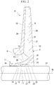
- Fig. 2 illustrates a region A in Fig. 1 in an enlarged manner.
- the impeller 4 according to the present embodiment has a disk 8, a blade 9, and a cover 10.
- the disk 8 is composed of two members. More specifically, the disk 8 has a tubular first disk member 11 centered on the axis Ac, and a disk-shaped second disk member 12 provided on a first side of the first disk member 11 in the direction of the axis Ac.
- An outer peripheral surface (first disk outer peripheral surface 13) of the first disk member 11 is gradually reduced in diameter from the first side toward a second side in the direction of the axis Ac.
- the first disk outer peripheral surface 13 is inclined in a gentle curved shape with respect to the axis Ac.
- the first disk outer peripheral surface 13 forms a part of an impeller flow passage Fi to be described below.
- a space on the inner peripheral side of the first disk member 11 is a first insertion hole 14 into which the rotor 1 is inserted.
- the first insertion hole 14 has a circular section as viewed from the direction of the axis Ac, and has a constant inner diameter along the axis Ac.
- An annular groove (recessed portion 15) into which an insertion portion 22 (to be described below) of the second disk member 12 is inserted is formed in a portion including one end of the first insertion hole 14 in the direction of the axis Ac.
- the recessed portion 15 is recessed around the axis Ac from a first side toward a second side in the direction of the axis Ac.
- a surface, facing the first side in the direction of the axis Ac, within the recessed portion 15 is a recessed portion bottom surface 16.
- a surface of the recessed portion 15 facing radially inward with respect to the axis Ac is a recessed portion inner peripheral surface 17.
- the recessed portion bottom surface 16 has an annular shape centered on the axis Ac.
- the recessed portion inner peripheral surface 17 has a tubular shape centered on the axis Ac.
- a portion (fitting portion 19) of the first insertion hole 14 except for the recessed portion 15 on an inner peripheral surface (insertion hole inner peripheral surface 18) is shrink-fitted to the outer peripheral surface of the rotor 1.
- a surface of the first disk member 11 facing the first side in the direction of the axis Ac is a first end surface 20.
- the second disk member 12 has a disk-shaped second disk member body 21 centered on the axis Ac, and the insertion portion 22 protruding from the second disk member body 21 in the direction of the axis Ac.
- a second insertion hole 23 into which the rotor 1 is inserted is formed at the position of the axis Ac of the second disk member body 21.
- the second insertion hole 23 has a circular section as viewed from the direction of the axis Ac, and has the same inner diameter as that of the above-described first insertion hole 14.
- the inner diameter of the second insertion hole 23 is constant along the axis Ac.
- a surface of the second disk member body 21 facing the second side in the direction of the axis Ac includes a second end surface 24 located relatively on the inner peripheral side, and a main surface 25 located relatively on the outer peripheral side of the second end surface 24.
- the second end surface 24 faces the above-described first end surface 20 via a gap (a second gap 31 to be described below).
- the blade 9 is disposed on the main surface 25 and forms a part of the impeller flow passage Fi.
- the main surface 25 is a portion of the surface of the second disk member body 21 facing the second side in the direction of the axis Ac, excluding the above second end surface 24.
- the surface of the second disk member body 21 that faces the first side in the direction of the axis Ac is a back surface 26.
- the insertion portion 22 has a cylindrical shape protruding from the second disk member body 21 to the second side in the direction of the axis Ac around the axis Ac.
- An inner peripheral surface of the insertion portion 22 (an insertion portion inner peripheral surface 27) has the same inner diameter as that of the second insertion hole 23, and both are continuous with each other. In other words, no step is formed between the insertion portion inner peripheral surface 27 and the second insertion hole 23.
- a surface of the insertion portion 22 facing the second side in the direction of the axis Ac is an insertion portion end surface 28.
- the surface of the insertion portion 22 that faces radially outward is an insertion portion outer peripheral surface 29.
- the insertion portion end surface 28 faces the recessed portion bottom surface 16 with a gap (first gap 30) broadening in the direction of the axis Ac.
- the insertion portion outer peripheral surface 29 abuts against the recessed portion inner peripheral surface 17.
- the first end surface 20 faces the second end surface 24 with a gap (second gap 31) broadening in the direction of the axis Ac.
- An angular portion formed by the insertion portion end surface 28 and the insertion portion outer peripheral surface 29 is a first angular portion 32.
- the first angular portion 32 is surrounded from the outside by a first groove 33 formed at a connection portion between the recessed portion bottom surface 16 and the recessed portion inner peripheral surface 17.
- the first groove 33 recedes toward the second side in the direction of the axis Ac from the recessed portion bottom surface 16 and recedes radially outward from the recessed portion inner peripheral surface 17.
- the first groove 33 has a substantially arc-shaped section.
- the angular portion formed by the recessed portion inner peripheral surface 17 and the first end surface 20 is a second angular portion 34.
- the second angular portion 34 is surrounded from the outside by a second groove 35 formed at a connection portion between the insertion portion outer peripheral surface 29 and the second end surface 24.
- the second groove 35 recedes radially inward from the insertion portion outer peripheral surface 29, and recedes toward a first side in the direction of the axis Ac from the second end surface 24.
- the second groove 35 has a substantially arc-shaped section.
- a plurality of the blades 9 are arranged at intervals around the axis Ac in the circumferential direction on the main surface 25 of the above-described second disk member body 21.
- each blade 9 is curved from a first side to a second side in the circumferential direction as being closer to the outside from the inside in the radial direction.
- a funnel-shaped cover 10 centered on the axis Ac is attached to an edge on the outer peripheral side of the blade 9.
- a space surrounded by the main surface 25, a pair of the circumferentially adjacent blades 9, and the inner peripheral surface of the cover 10 (cover inner peripheral surface 36) is the impeller flow passage Fi. That is, within the impeller 4, a plurality of the impeller flow passages Fi are arranged radially around the axis Ac.
- a rotating force is applied to the shaft end of the rotor 1 by the above-described electric motor (not illustrated) or the like.
- the plurality of impellers 4 rotate with the rotation of the rotor 1.
- an external working fluid for example, air
- the working fluid taken into the casing flow passage Fc is compressed in the course of alternately passing through the above-described impeller flow passage Fi and casing flow passage Fc, and is brought into a high-pressure state.
- the working fluid brought into a high-pressure state is discharged from the exhaust port 6 to the outside.
- a centrifugal force accompanying rotation and a pressure based on a differential pressure between the main surface 25 and the back surface 26 are added to the impellers 4 during operation. Due to such centrifugal force and pressure, stress is generated at the joined portion between the first disk member 11 and the second disk member 12. Particularly, in the vicinity of the first angular portion 32 and the above-described second angular portion 34, stress tends to concentrate, and the possibility of fretting fatigue based on the stress also occurs.
- the first groove 33 is formed so as to surround the first angular portion 32
- the second groove 35 is formed so as to surround the second angular portion 34.
- the first angular portion 32 formed by the insertion portion end surface 28 and the insertion portion outer peripheral surface 29 is surrounded by the first groove 33.
- the stress is released by the first groove 33. Accordingly, the stress generated at the insertion portion end surface 28 can be relaxed as compared to a configuration in which the first groove 33 is not provided.
- the stress concentration at the angular portion formed by the insertion portion end surface 28 and the insertion portion outer peripheral surface 29 can be reduced.
- the second angular portion 34 formed by the recessed portion inner peripheral surface 17 and the first end surface 20 is surrounded by the second groove 35.
- the stress generated on the first end surface 20 can be relaxed as compared to the configuration in which the second groove 35 is not provided.
- the stress concentration at the angular portion formed by the recessed portion inner peripheral surface 17 and the first end surface 20 can be reduced.
- the first groove 33 and the second groove 35 are formed over the entire region in the circumferential direction. For that reason, it is possible to release the stress evenly over the entire region in the circumferential direction. In other words, local stress concentration in the circumferential direction can be avoided.
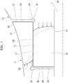
- Fig. 4 the magnitude of a stress generated in the vicinity of the above-described first angular portion 32 and second angular portion 34 is indicated by the length of arrows, and the magnitude of ae stress distribution in a case where the first groove 33 and the second groove 35 are formed indicated by solid lines.
- the stress increases from the outside toward the inside in the radial direction.
- the stress increases from the inside to the outside in the radial direction.
- dashed lines indicate stress distributions in a case where the first groove 33 and the second groove 35 are not formed.
- both the stresses in the direction of the axis Ac in the vicinity of the first angular portion 32 and the second angular portion 34 are reduced compared to a case where the first groove 33 and the second groove 35 are not formed.
- the stress concentration at the joined portion between the first disk member 11 and the second disk member 12 can be relaxed, and the possibility of fretting fatigue based on this can be reduced. Accordingly, the highly reliable impeller 4 and the centrifugal compressor 100 including the impeller 4 can be provided.
- first embodiment of the present invention has been described above.
- various changes and modifications can be made to the above configuration without departing from the scope of the attached claims .
- the aspect of the first groove 33 and the second groove 35 is not limited to the above, and for example, it is also possible to adopt a configuration in which the first groove 33 and the second groove 35 are discontinuously formed at equal intervals in the circumferential direction.
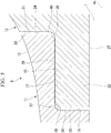
- a first tapered surface 37 is formed between the insertion portion end surface 28 and the insertion portion outer peripheral surface 29.
- the first tapered surface 37 broadens in a direction intersecting the axis Ac.
- the first tapered surface 37 forms 45 ° with respect to the axis Ac in a sectional view including the axis Ac.
- the first tapered surface 37 is continuously formed over the entire region in the circumferential direction with respect to the axis Ac.
- a first rounded portion 38 is formed between the recessed portion bottom surface 16 and the recessed portion inner peripheral surface 17.
- the first rounded portion 38 has a substantially arcuate shape in a sectional view including the axis Ac. Specifically, the first rounded portion 38 gradually curves from the recessed portion bottom surface 16 toward the recessed portion inner peripheral surface 17.
- the first rounded portion 38 faces the first tapered surface 37 from the direction of the axis Ac. Additionally, a gap is formed between the first rounded portion 38 and the first tapered surface 37, and both do not abut against each other.
- the second rounded portion 40 is continuously formed over the entire region in the circumferential direction with respect to the axis Ac.
- a second tapered surface 39 is formed on the recessed portion inner peripheral surface 17 and the first end surface 20.
- the second tapered surface 39 broadens in a direction intersecting the axis Ac.
- the second tapered surface 39 forms 45° with respect to the axis Ac in a sectional view including the axis Ac.
- the second tapered surface 39 is continuously formed over the entire region in the circumferential direction with respect to the axis Ac.
- a second rounded portion 40 is formed between the insertion portion outer peripheral surface 29 and the second end surface 24.
- the second rounded portion 40 has a substantially arcuate shape in a sectional view including the axis Ac. Specifically, the second rounded portion 40 gradually curves from the insertion portion outer peripheral surface 29 toward the second end surface 24. The second rounded portion 40 faces the second tapered portion from the direction of the axis Ac. Additionally, a gap is formed between the second rounded portion 40 and the second tapered surface 39, and both do not abut against each other. The second rounded portion 40 is continuously formed over the entire region in the circumferential direction with respect to the axis Ac.
- the first tapered surface 37 is formed between the insertion portion end surface 28 and the insertion portion outer peripheral surface 29. For that reason, in a case where a centrifugal force or a differential pressure on both sides in the direction of the axis Ac is applied to the disk 8, the stress is released by the first tapered surface 37. Accordingly, the stress generated on the insertion portion end surface 28 can be relaxed as compared to a configuration in which the first tapered surface 37 is not provided. Moreover, the first rounded portion 38 is formed between the recessed portion bottom surface 16 and the recessed portion inner peripheral surface 17.
- the stress concentration in the portion can be relaxed.
- a large curvature radius of the first rounded portion 38 can be secured.
- the second tapered surface 39 is formed between the recessed portion inner peripheral surface 17 and the first end surface 20. For that reason, in a case where a centrifugal force or a differential pressure is applied, the stress is released by the second tapered surface 39. Accordingly, the stress generated on the first end surface 20 can be relaxed as compared to a configuration in which the second tapered surface 39 is not provided.
- the second rounded portion 40 is formed between the insertion portion outer peripheral surface 29 and the second end surface 24. Accordingly, for example, as compared to a case where an angular portion is formed between the insertion portion outer peripheral surface 29 and the second end surface 24, the stress concentration in the portion can be relaxed. Additionally, particularly, by providing the second tapered surface 39, a large curvature radius of the second rounded portion 40 can be secured.
- the first tapered surface 37, the second tapered surface 39, the first rounded portion 38, and the second rounded portion 40 are formed over the entire region in the circumferential direction. For that reason, it is possible to release the stress evenly over the entire region in the circumferential direction. In other words, local stress concentration in the circumferential direction can be avoided.
- the stress concentration at the joined portion between the first disk member 11 and the second disk member 12 can be relaxed, and the possibility of fretting fatigue based on this can be reduced. Accordingly, the highly reliable impeller 4 and the centrifugal compressor 100 including the impeller 4 can be provided.
- first tapered surface 37, the second tapered surface 39, the first rounded portion 38, and the second rounded portion 40 are not limited to the above, and it is also possible to adopt, for example, a configuration in which the first tapered surface 37, the second tapered surface 39, the first rounded portion 38, and the second rounded portion 40 are discontinuously formed at equal intervals in the circumferential direction.
- a third groove 41 is formed in the insertion portion end surface 28, and a fourth groove 42 is formed in the first end surface 20.
- the third groove 41 is recessed from the insertion portion end surface 28 toward a first side in the direction of the axis Ac.
- the third groove 41 is formed at a portion of the insertion portion end surface 28 that is close to a radially outer edge.
- the distance between the insertion portion outer peripheral surface 29 and the third groove 41 is smaller than the distance between the insertion portion inner peripheral surface 27 and the third groove 41. Accordingly, in a case where a force is applied from the radial outside, the portion radially outside the third groove 41 is elastically deformed like a spring. In other words, the portion radially outside the third groove 41 has lower rigidity than the other portions. In addition, the third groove 41 is continuously formed over the entire region in the circumferential direction with respect to the axis Ac.
- the fourth groove 42 is recessed from the first end surface 20 toward a second side in the direction of the axis Ac.
- the fourth groove 42 is formed at a portion of the first end surface 20 that is close to a radially inner edge.
- the distance between the recessed portion inner peripheral surface 17 and the fourth groove 42 is smaller than the distance between the first disk outer peripheral surface 13 and the fourth groove 42. Accordingly, in a case where a force is applied from the radial outside, the portion radially inside the fourth groove 42 is elastically deformed like a spring.
- the portion radially inside the fourth groove 42 has lower rigidity than the other portions.
- the fourth groove 42 is continuously formed over the entire region in the circumferential direction with respect to the axis Ac.
- the third groove 41 is formed in the insertion portion end surface 28. For that reason, in a case where a stress is exerted from the direction along the insertion portion end surface 28, the third groove 41 is elastically deformed so as to be crushed from both sides in the radial direction with respect to the axis Ac. That is, the rigidity of the insertion portion end surface 28 is reduced, and the stress can be released.
- the fourth groove 42 is formed in the first end surface 20. For that reason, in a case where a stress is exerted from the direction along the first end surface 20, the fourth groove 42 is elastically deformed so as to be crushed from both sides in the radial direction with respect to the axis Ac. That is, the rigidity of the first end surface 20 is reduced, and the stress can be released.
- the third groove 41 and the fourth groove 42 are formed over the entire region in the circumferential direction. For that reason, it is possible to release the stress evenly over the entire region in the circumferential direction. In other words, local stress concentration in the circumferential direction can be avoided.
- the third groove 41 and the fourth groove 42 described above are also applied in combination with the first groove 33 and the second groove 35 in the above-described first embodiment.
- the third groove 41 and the fourth groove 42 are applied in combination with the first tapered surface 37, the second tapered surface 39, the first rounded portion 38, and the second rounded portion 40 in the above-described second embodiment. In either configuration, the stress generated at the joined portion between the first disk member 11 and the second disk member 12 can be further relaxed, and the possibility of fretting fatigue can be reduced.
Landscapes
- Engineering & Computer Science (AREA)
- Mechanical Engineering (AREA)
- General Engineering & Computer Science (AREA)
- Structures Of Non-Positive Displacement Pumps (AREA)
Claims (6)
- Impeller (4), aufweisend:eine Scheibe (8) mit einem ersten Scheibenelement (11), das eine röhrenförmige Form zentriert an einer Achse (Ac) hat, und einem zweiten Scheibenelement (12), das eine röhrenförmige Form zentriert an der Achse hat und auf einer ersten Seite des ersten Scheibenelements in einer Richtung der Achse (Ac) angeordnet ist;ein Blatt(10), das integral mit dem zweiten Scheibenelement (12) ausgebildet ist; undeine Abdeckung (10), die eine Strömungspassage zwischen der Abdeckung (10) und dem zweiten Scheibenelement (12) bildet, indem sie das Blatt (9) von einer Außenumfangsseite bedeckt;wobei ein Vertiefungsabschnitt (15), der von der ersten Seite in Richtung einer zweiten Seite in der Richtung der Achse (Ac) vertieft ist, in einer Ringform um die Achse in dem ersten Scheibenelement (11) gebildet ist,wobei das zweite Scheibenelement (12) einen zweiten Scheibenelementkörper (21), der in einer Scheibenform um die Achse gebildet ist, und einen Einführabschnitt (22) aufweist, der von dem zweiten Scheibenelementkörper (21) in Richtung der zweiten Seite in der Richtung der Achse (Ac) um die Achse vorsteht und in den Vertiefungsabschnitt (15) eingeführt ist,dadurch gekennzeichnet, dasseine erste Nut (33), welche von der Außenseite einen ersten Winkelabschnitt (30) umgibt, der von einer Einführabschnittendfläche (28) des Einführabschnitts, die der zweiten Seite in der Richtung der Achse zugewandt ist, und einer Einführabschnittaußenumfangsfläche (29) des Einführabschnitts, die in Bezug auf die Achse radial nach außen weist, gebildet wird, hin zu der zweiten Seite in der Richtung der Achse von einer Vertiefungsabschnittbodenfläche (16) abfällt und radial nach außen in Bezug auf die Achse von einer Vertiefungsabschnittinnenumfangsfläche (17) abfällt, an einem Verbindungsabschnitt zwischen der Vertiefungsabschnittbodenfläche (16), die der ersten Seite in der Richtung der Achse zugewandt ist, und der Vertiefungsabschnittinnenumfangsfläche (17), die in Bezug auf die Richtung der Achse des Vertiefungsabschnitts radial nach innen weist, gebildet ist, undeine zweite Nut (35), welche von der Außenseite einen zweiten Winkelabschnitt (34) umgibt, der von der Vertiefungsabschnittinnenumfangsfläche (17) und einer ersten Endfläche (20) des ersten Scheibenelements, die der ersten Seite in der Richtung der Achse zugewandt ist, gebildet wird, radial nach innen in Bezug auf die Achse von der Einführabschnittaußenumfangsfläche abfällt und hin zu der ersten Seite in der Richtung der Achse von einer zweiten Endfläche (24) abfällt, an einem Verbindungsabschnitt zwischen der Einführabschnittaußenumfangsfläche und der zweiten Endfläche (24) des zweiten Scheibenelementkörpers, die der zweiten Seite in der Richtung der Achse zugewandt ist, gebildet ist,eine dritte Nut (41), die von der Einführabschnittendfläche (28) hin zu der ersten Seite in der Richtung der Achse vertieft ist, in der Einführabschnittendfläche (28) gebildet ist,eine vierte Nut (42), die von der ersten Endfläche (20) hin zu der zweiten Seite in der Richtung der Achse vertieft ist, in der ersten Endfläche (20) gebildet ist,der Abstand zwischen der Einführabschnittaußenumfangsfläche (29) und der dritten Nut (41) kleiner als der Abstand zwischen einer Innenfläche des Einführabschnitts (22), welche eine Einführabschnittinnenumfangsfläche (27) ist, und der dritten Nut (41) ist, undder Abstand zwischen der Vertiefungsabschnittinnenumfangsfläche (17) und der vierten Nut (42) kleiner als der Abstand zwischen einer Außenfläche des ersten Scheibenelements (11), welche einer erste Scheibenaußenumfangsfläche (13) ist, und der vierten Nut (42) ist.
- Impeller nach Anspruch 1,
wobei die erste Nut (33) und die zweite Nut (35) über einen gesamten Bereich in einer Umfangsrichtung in Bezug auf die Achse (Ac) gebildet sind. - Impeller (4), aufweisend:eine Scheibe (8) mit einem ersten Scheibenelement (11), das eine röhrenförmige Form zentriert an einer Achse (Ac) hat, und einem zweiten Scheibenelement (12), das eine röhrenförmige Form zentriert an der Achse hat und auf einer ersten Seite des ersten Scheibenelements in einer Richtung der Achse angeordnet ist;ein Blatt (9), das integral mit dem zweiten Scheibenelement ausgebildet ist; undeine Abdeckung (10), die eine Strömungspassage zwischen der Abdeckung und dem zweiten Scheibenelement bildet, indem sie das Blatt von einer Außenumfangsseite bedeckt;wobei ein Vertiefungsabschnitt (15), der von der ersten Seite in Richtung einer zweiten Seite in der Richtung der Achse vertieft ist, in einer Ringform um die Achse in dem ersten Scheibenelement (11) gebildet ist,wobei das zweite Scheibenelement (12) einen zweiten Scheibenelementkörper (21), der in einer Scheibenform um die Achse gebildet ist, und einen Einführabschnitt (11) aufweist, der von dem zweiten Scheibenelementkörper in Richtung der zweiten Seite in der Richtung der Achse um die Achse vorsteht und in den Vertiefungsabschnitt (15) eingeführt ist,dadurch gekennzeichnet, dassein erster verjüngter Abschnitt (37), der sich in einer Richtung weitet, welche die Achse schneidet, zwischen einer Einführabschnittendfläche (28) des Einführabschnitts, die der zweiten Seite in der Richtung der Achse zugewandt ist, und einer Einführabschnittaußenumfangsfläche (29) des Einführabschnitts, die in Bezug auf die Achse radial nach außen weist, gebildet ist,ein erster abgerundeter Abschnitt (38), der sich allmählich von einer Vertiefungsabschnittbodenfläche (16) hin zu einer Vertiefungsabschnittinnenumfangsfläche (17) krümmt, zwischen der Vertiefungsabschnittbodenfläche (16), die der ersten Seite in der Richtung der Achse zugewandt ist, und der Vertiefungsabschnittinnenumfangsfläche (17), die in Bezug auf die Richtung der Achse in dem Vertiefungsabschnitt radial nach innen weist, gebildet ist,eine zweite verjüngte Fläche (39), welche sich in einer Richtung weitet, welche die Achse schneidet, zwischen der Vertiefungsabschnittinnenumfangsfläche (17) und einer ersten Endfläche (20) des ersten Scheibenelements, die der ersten Seite in der Richtung der Achse zugewandt ist, gebildet ist, undein zweiter abgerundeter Abschnitt (40), der sich allmählich von der Einführabschnittaußenumfangsfläche hin zu einer zweiten Endfläche (24) krümmt, zwischen der Einführabschnittaußenumfangsfläche und der zweiten Endfläche (24) des zweiten Scheibenelementkörpers, die der zweiten Seite in der Richtung der Achse zugewandt ist, gebildet ist,eine dritte Nut (41), die von der Einführabschnittendfläche (28) hin zu der ersten Seite in der Richtung der Achse vertieft ist, in der Einführabschnittendfläche (28) gebildet ist, undeine vierte Nut (42), die von der ersten Endfläche (20) hin zu der zweiten Seite in der Richtung der Achse vertieft ist, in der ersten Endfläche (20) gebildet ist,der Abstand zwischen der Einführabschnittaußenumfangsfläche (29) und der dritten Nut (41) kleiner als der Abstand zwischen einer Innenfläche des Einführabschnitts (22), welche eine Einführabschnittinnenumfangsfläche (27) ist, und der dritten Nut (41) ist, undder Abstand zwischen der Vertiefungsabschnittinnenumfangsfläche (17) und der vierten Nut (42) kleiner als der Abstand zwischen einer Außenfläche des ersten Scheibenelements (11), welche einer erste Scheibenaußenumfangsfläche (13) ist, und der vierten Nut (42) ist.
- Impeller nach Anspruch 3,
wobei die erste verjüngte Oberfläche (37), die zweite verjüngte Oberfläche (39), der erste abgerundete Abschnitt (38), und der zweite abgerundete Abschnitt (40) über einen gesamten Bereich in einer Umfangsrichtung in Bezug auf die Achse (Ac) gebildet sind. - Impeller nach einem der Ansprüche 1 bis 4,
wobei die dritte Nut (41) und die vierte Nut (42) über einen gesamten Bereich in einer Umfangsrichtung in Bezug auf die Achse gebildet sind. - Drehende Maschine (100), aufweisend:den Impeller (4) nach einem der Ansprüche 1 bis 5, undein Gehäuse (5), welches den Impeller von einer Außenumfangsseite abdeckt.
Applications Claiming Priority (2)
| Application Number | Priority Date | Filing Date | Title |
|---|---|---|---|
| JP2017229547A JP6936126B2 (ja) | 2017-11-29 | 2017-11-29 | インペラ、回転機械 |
| PCT/JP2018/041819 WO2019107132A1 (ja) | 2017-11-29 | 2018-11-12 | インペラ、回転機械 |
Publications (3)
| Publication Number | Publication Date |
|---|---|
| EP3686437A1 EP3686437A1 (de) | 2020-07-29 |
| EP3686437A4 EP3686437A4 (de) | 2020-11-11 |
| EP3686437B1 true EP3686437B1 (de) | 2022-01-05 |
Family
ID=66664457
Family Applications (1)
| Application Number | Title | Priority Date | Filing Date |
|---|---|---|---|
| EP18882965.9A Active EP3686437B1 (de) | 2017-11-29 | 2018-11-12 | Laufrad und drehmaschine |
Country Status (4)
| Country | Link |
|---|---|
| US (1) | US11280349B2 (de) |
| EP (1) | EP3686437B1 (de) |
| JP (1) | JP6936126B2 (de) |
| WO (1) | WO2019107132A1 (de) |
Families Citing this family (1)
| Publication number | Priority date | Publication date | Assignee | Title |
|---|---|---|---|---|
| JP2022068479A (ja) * | 2020-10-22 | 2022-05-10 | 三菱重工コンプレッサ株式会社 | 回転機械及びギアド圧縮機 |
Family Cites Families (14)
| Publication number | Priority date | Publication date | Assignee | Title |
|---|---|---|---|---|
| US2392858A (en) * | 1943-03-08 | 1946-01-15 | Gen Electric | High-speed rotor for centrifugal compressors and the like |
| DE1956777C3 (de) | 1969-07-30 | 1978-06-15 | E.I. Du Pont De Nemours And Co., Wilmington, Del. (V.St.A.) | Mischvorrichtung zur Herstellung von Isocyanaten |
| US3671140A (en) * | 1970-10-05 | 1972-06-20 | Avco Corp | Damped turbomachine rotor assembly |
| DE2621201C3 (de) * | 1976-05-13 | 1979-09-27 | Maschinenfabrik Augsburg-Nuernberg Ag, 8900 Augsburg | Laufrad für eine Strömungsmaschine |
| JP3346277B2 (ja) * | 1998-05-13 | 2002-11-18 | 株式会社日立製作所 | 圧縮機ロータ |
| US6033185A (en) | 1998-09-28 | 2000-03-07 | General Electric Company | Stress relieved dovetail |
| US6183202B1 (en) | 1999-04-30 | 2001-02-06 | General Electric Company | Stress relieved blade support |
| US7156612B2 (en) * | 2005-04-05 | 2007-01-02 | Pratt & Whitney Canada Corp. | Spigot arrangement for a split impeller |
| JP5538337B2 (ja) | 2011-09-29 | 2014-07-02 | 株式会社日立製作所 | 動翼 |
| JP5967966B2 (ja) * | 2012-02-13 | 2016-08-10 | 三菱重工コンプレッサ株式会社 | インペラ及びこれを備えた回転機械 |
| JP6131022B2 (ja) * | 2012-10-30 | 2017-05-17 | 三菱重工業株式会社 | インペラ及びこれを備えた回転機械 |
| JP6327505B2 (ja) | 2013-11-21 | 2018-05-23 | 三菱重工業株式会社 | インペラ及び回転機械 |
| US10731484B2 (en) * | 2014-11-17 | 2020-08-04 | General Electric Company | BLISK rim face undercut |
| JP6288900B1 (ja) | 2017-02-20 | 2018-03-07 | 三菱重工コンプレッサ株式会社 | インペラ、回転機械、インペラの製造方法、及び回転機械の製造方法 |
-
2017
- 2017-11-29 JP JP2017229547A patent/JP6936126B2/ja active Active
-
2018
- 2018-11-12 EP EP18882965.9A patent/EP3686437B1/de active Active
- 2018-11-12 US US16/757,552 patent/US11280349B2/en active Active
- 2018-11-12 WO PCT/JP2018/041819 patent/WO2019107132A1/ja not_active Ceased
Also Published As
| Publication number | Publication date |
|---|---|
| EP3686437A1 (de) | 2020-07-29 |
| JP2019100211A (ja) | 2019-06-24 |
| US11280349B2 (en) | 2022-03-22 |
| WO2019107132A1 (ja) | 2019-06-06 |
| US20210190087A1 (en) | 2021-06-24 |
| EP3686437A4 (de) | 2020-11-11 |
| JP6936126B2 (ja) | 2021-09-15 |
Similar Documents
| Publication | Publication Date | Title |
|---|---|---|
| CN108368743B (zh) | 阶梯型密封体、密封结构、透平机械及阶梯型密封体的制造方法 | |
| EP3636935B1 (de) | Zentrifugalblutpumpenlaufrad und -strömungsweg | |
| US9903385B2 (en) | Impeller, rotary machine including the same, and method for manufacturing impeller | |
| US20160362995A1 (en) | Rotor for a turbomachine and compressor | |
| EP2762676A1 (de) | Turbomaschinen-Rotorschaufel, Turbomaschinen-Rotorscheibe, Turbomaschinenrotor und Gasturbinenmotor mit unterschiedlichen Kontaktflächenwinkeln des Schaufelfusses und der Schaufelnut | |
| CN105275883B (zh) | 压缩机和压缩机的制造方法 | |
| JPWO2016038661A1 (ja) | 回転機械 | |
| CN104251232B (zh) | 具有双重叶片固定方式的轴流式涡轮机压缩机鼓轮 | |
| JP6209199B2 (ja) | シールフィン,シール構造,ターボ機械及びシールフィンの製造方法 | |
| EP3686437B1 (de) | Laufrad und drehmaschine | |
| EP3346138A1 (de) | Einstellverfahren für rotorauswuchtung | |
| EP2855888B1 (de) | Segmentierte dichtung mit stufenfalzenden | |
| US20230175527A1 (en) | Turbomachine compressor having a stationary wall provided with a shape treatment | |
| EP3715636A1 (de) | Drehmaschine | |
| EP3346137B1 (de) | Rotor eines zentrifugalkompressors, zentrifugalkompressor und verfahren zur herstellung eines rotors eines zentrifugalkompressors | |
| EP3557076B1 (de) | Laufrad, drehmaschine, verfahren zur herstellung eines laufrads und verfahren zur herstellung einer drehmaschine | |
| JP2006183475A (ja) | 遠心圧縮機 | |
| JP2019105183A (ja) | 可変静翼、及び圧縮機 | |
| US11613997B2 (en) | Steam turbine | |
| KR100745507B1 (ko) | 터보 압축기 | |
| JP2014169704A (ja) | インペラ | |
| HK40015801B (en) | Centrifugal blood pump impeller and flow path | |
| EP3379087A1 (de) | Ringdichtung für einen kreiselverdichter | |
| HK40015801A (en) | Centrifugal blood pump impeller and flow path | |
| HK1236594B (en) | Centrifugal pump impeller |
Legal Events
| Date | Code | Title | Description |
|---|---|---|---|
| STAA | Information on the status of an ep patent application or granted ep patent |
Free format text: STATUS: THE INTERNATIONAL PUBLICATION HAS BEEN MADE |
|
| PUAI | Public reference made under article 153(3) epc to a published international application that has entered the european phase |
Free format text: ORIGINAL CODE: 0009012 |
|
| STAA | Information on the status of an ep patent application or granted ep patent |
Free format text: STATUS: REQUEST FOR EXAMINATION WAS MADE |
|
| 17P | Request for examination filed |
Effective date: 20200421 |
|
| AK | Designated contracting states |
Kind code of ref document: A1 Designated state(s): AL AT BE BG CH CY CZ DE DK EE ES FI FR GB GR HR HU IE IS IT LI LT LU LV MC MK MT NL NO PL PT RO RS SE SI SK SM TR |
|
| AX | Request for extension of the european patent |
Extension state: BA ME |
|
| A4 | Supplementary search report drawn up and despatched |
Effective date: 20201013 |
|
| RIC1 | Information provided on ipc code assigned before grant |
Ipc: F04D 29/28 20060101AFI20201007BHEP Ipc: F04D 29/62 20060101ALI20201007BHEP Ipc: F04D 29/26 20060101ALI20201007BHEP |
|
| DAV | Request for validation of the european patent (deleted) | ||
| DAX | Request for extension of the european patent (deleted) | ||
| GRAP | Despatch of communication of intention to grant a patent |
Free format text: ORIGINAL CODE: EPIDOSNIGR1 |
|
| STAA | Information on the status of an ep patent application or granted ep patent |
Free format text: STATUS: GRANT OF PATENT IS INTENDED |
|
| INTG | Intention to grant announced |
Effective date: 20210721 |
|
| GRAS | Grant fee paid |
Free format text: ORIGINAL CODE: EPIDOSNIGR3 |
|
| GRAA | (expected) grant |
Free format text: ORIGINAL CODE: 0009210 |
|
| STAA | Information on the status of an ep patent application or granted ep patent |
Free format text: STATUS: THE PATENT HAS BEEN GRANTED |
|
| AK | Designated contracting states |
Kind code of ref document: B1 Designated state(s): AL AT BE BG CH CY CZ DE DK EE ES FI FR GB GR HR HU IE IS IT LI LT LU LV MC MK MT NL NO PL PT RO RS SE SI SK SM TR |
|
| REG | Reference to a national code |
Ref country code: GB Ref legal event code: FG4D |
|
| REG | Reference to a national code |
Ref country code: CH Ref legal event code: EP |
|
| REG | Reference to a national code |
Ref country code: AT Ref legal event code: REF Ref document number: 1460839 Country of ref document: AT Kind code of ref document: T Effective date: 20220115 |
|
| REG | Reference to a national code |
Ref country code: DE Ref legal event code: R096 Ref document number: 602018029377 Country of ref document: DE |
|
| REG | Reference to a national code |
Ref country code: IE Ref legal event code: FG4D |
|
| REG | Reference to a national code |
Ref country code: LT Ref legal event code: MG9D |
|
| REG | Reference to a national code |
Ref country code: NL Ref legal event code: MP Effective date: 20220105 |
|
| REG | Reference to a national code |
Ref country code: AT Ref legal event code: MK05 Ref document number: 1460839 Country of ref document: AT Kind code of ref document: T Effective date: 20220105 |
|
| PG25 | Lapsed in a contracting state [announced via postgrant information from national office to epo] |
Ref country code: NL Free format text: LAPSE BECAUSE OF FAILURE TO SUBMIT A TRANSLATION OF THE DESCRIPTION OR TO PAY THE FEE WITHIN THE PRESCRIBED TIME-LIMIT Effective date: 20220105 |
|
| PG25 | Lapsed in a contracting state [announced via postgrant information from national office to epo] |
Ref country code: SE Free format text: LAPSE BECAUSE OF FAILURE TO SUBMIT A TRANSLATION OF THE DESCRIPTION OR TO PAY THE FEE WITHIN THE PRESCRIBED TIME-LIMIT Effective date: 20220105 Ref country code: RS Free format text: LAPSE BECAUSE OF FAILURE TO SUBMIT A TRANSLATION OF THE DESCRIPTION OR TO PAY THE FEE WITHIN THE PRESCRIBED TIME-LIMIT Effective date: 20220105 Ref country code: PT Free format text: LAPSE BECAUSE OF FAILURE TO SUBMIT A TRANSLATION OF THE DESCRIPTION OR TO PAY THE FEE WITHIN THE PRESCRIBED TIME-LIMIT Effective date: 20220505 Ref country code: NO Free format text: LAPSE BECAUSE OF FAILURE TO SUBMIT A TRANSLATION OF THE DESCRIPTION OR TO PAY THE FEE WITHIN THE PRESCRIBED TIME-LIMIT Effective date: 20220405 Ref country code: LT Free format text: LAPSE BECAUSE OF FAILURE TO SUBMIT A TRANSLATION OF THE DESCRIPTION OR TO PAY THE FEE WITHIN THE PRESCRIBED TIME-LIMIT Effective date: 20220105 Ref country code: HR Free format text: LAPSE BECAUSE OF FAILURE TO SUBMIT A TRANSLATION OF THE DESCRIPTION OR TO PAY THE FEE WITHIN THE PRESCRIBED TIME-LIMIT Effective date: 20220105 Ref country code: ES Free format text: LAPSE BECAUSE OF FAILURE TO SUBMIT A TRANSLATION OF THE DESCRIPTION OR TO PAY THE FEE WITHIN THE PRESCRIBED TIME-LIMIT Effective date: 20220105 Ref country code: BG Free format text: LAPSE BECAUSE OF FAILURE TO SUBMIT A TRANSLATION OF THE DESCRIPTION OR TO PAY THE FEE WITHIN THE PRESCRIBED TIME-LIMIT Effective date: 20220405 |
|
| PG25 | Lapsed in a contracting state [announced via postgrant information from national office to epo] |
Ref country code: PL Free format text: LAPSE BECAUSE OF FAILURE TO SUBMIT A TRANSLATION OF THE DESCRIPTION OR TO PAY THE FEE WITHIN THE PRESCRIBED TIME-LIMIT Effective date: 20220105 Ref country code: LV Free format text: LAPSE BECAUSE OF FAILURE TO SUBMIT A TRANSLATION OF THE DESCRIPTION OR TO PAY THE FEE WITHIN THE PRESCRIBED TIME-LIMIT Effective date: 20220105 Ref country code: GR Free format text: LAPSE BECAUSE OF FAILURE TO SUBMIT A TRANSLATION OF THE DESCRIPTION OR TO PAY THE FEE WITHIN THE PRESCRIBED TIME-LIMIT Effective date: 20220406 Ref country code: FI Free format text: LAPSE BECAUSE OF FAILURE TO SUBMIT A TRANSLATION OF THE DESCRIPTION OR TO PAY THE FEE WITHIN THE PRESCRIBED TIME-LIMIT Effective date: 20220105 Ref country code: AT Free format text: LAPSE BECAUSE OF FAILURE TO SUBMIT A TRANSLATION OF THE DESCRIPTION OR TO PAY THE FEE WITHIN THE PRESCRIBED TIME-LIMIT Effective date: 20220105 |
|
| PG25 | Lapsed in a contracting state [announced via postgrant information from national office to epo] |
Ref country code: IS Free format text: LAPSE BECAUSE OF FAILURE TO SUBMIT A TRANSLATION OF THE DESCRIPTION OR TO PAY THE FEE WITHIN THE PRESCRIBED TIME-LIMIT Effective date: 20220505 |
|
| REG | Reference to a national code |
Ref country code: DE Ref legal event code: R097 Ref document number: 602018029377 Country of ref document: DE |
|
| PG25 | Lapsed in a contracting state [announced via postgrant information from national office to epo] |
Ref country code: SM Free format text: LAPSE BECAUSE OF FAILURE TO SUBMIT A TRANSLATION OF THE DESCRIPTION OR TO PAY THE FEE WITHIN THE PRESCRIBED TIME-LIMIT Effective date: 20220105 Ref country code: SK Free format text: LAPSE BECAUSE OF FAILURE TO SUBMIT A TRANSLATION OF THE DESCRIPTION OR TO PAY THE FEE WITHIN THE PRESCRIBED TIME-LIMIT Effective date: 20220105 Ref country code: RO Free format text: LAPSE BECAUSE OF FAILURE TO SUBMIT A TRANSLATION OF THE DESCRIPTION OR TO PAY THE FEE WITHIN THE PRESCRIBED TIME-LIMIT Effective date: 20220105 Ref country code: EE Free format text: LAPSE BECAUSE OF FAILURE TO SUBMIT A TRANSLATION OF THE DESCRIPTION OR TO PAY THE FEE WITHIN THE PRESCRIBED TIME-LIMIT Effective date: 20220105 Ref country code: DK Free format text: LAPSE BECAUSE OF FAILURE TO SUBMIT A TRANSLATION OF THE DESCRIPTION OR TO PAY THE FEE WITHIN THE PRESCRIBED TIME-LIMIT Effective date: 20220105 Ref country code: CZ Free format text: LAPSE BECAUSE OF FAILURE TO SUBMIT A TRANSLATION OF THE DESCRIPTION OR TO PAY THE FEE WITHIN THE PRESCRIBED TIME-LIMIT Effective date: 20220105 |
|
| PLBE | No opposition filed within time limit |
Free format text: ORIGINAL CODE: 0009261 |
|
| STAA | Information on the status of an ep patent application or granted ep patent |
Free format text: STATUS: NO OPPOSITION FILED WITHIN TIME LIMIT |
|
| PG25 | Lapsed in a contracting state [announced via postgrant information from national office to epo] |
Ref country code: AL Free format text: LAPSE BECAUSE OF FAILURE TO SUBMIT A TRANSLATION OF THE DESCRIPTION OR TO PAY THE FEE WITHIN THE PRESCRIBED TIME-LIMIT Effective date: 20220105 |
|
| 26N | No opposition filed |
Effective date: 20221006 |
|
| PG25 | Lapsed in a contracting state [announced via postgrant information from national office to epo] |
Ref country code: SI Free format text: LAPSE BECAUSE OF FAILURE TO SUBMIT A TRANSLATION OF THE DESCRIPTION OR TO PAY THE FEE WITHIN THE PRESCRIBED TIME-LIMIT Effective date: 20220105 |
|
| PG25 | Lapsed in a contracting state [announced via postgrant information from national office to epo] |
Ref country code: MC Free format text: LAPSE BECAUSE OF FAILURE TO SUBMIT A TRANSLATION OF THE DESCRIPTION OR TO PAY THE FEE WITHIN THE PRESCRIBED TIME-LIMIT Effective date: 20220105 |
|
| REG | Reference to a national code |
Ref country code: CH Ref legal event code: PL |
|
| GBPC | Gb: european patent ceased through non-payment of renewal fee |
Effective date: 20221112 |
|
| REG | Reference to a national code |
Ref country code: BE Ref legal event code: MM Effective date: 20221130 |
|
| PG25 | Lapsed in a contracting state [announced via postgrant information from national office to epo] |
Ref country code: LI Free format text: LAPSE BECAUSE OF NON-PAYMENT OF DUE FEES Effective date: 20221130 Ref country code: CH Free format text: LAPSE BECAUSE OF NON-PAYMENT OF DUE FEES Effective date: 20221130 |
|
| PG25 | Lapsed in a contracting state [announced via postgrant information from national office to epo] |
Ref country code: LU Free format text: LAPSE BECAUSE OF NON-PAYMENT OF DUE FEES Effective date: 20221112 |
|
| PG25 | Lapsed in a contracting state [announced via postgrant information from national office to epo] |
Ref country code: IE Free format text: LAPSE BECAUSE OF NON-PAYMENT OF DUE FEES Effective date: 20221112 Ref country code: GB Free format text: LAPSE BECAUSE OF NON-PAYMENT OF DUE FEES Effective date: 20221112 |
|
| PG25 | Lapsed in a contracting state [announced via postgrant information from national office to epo] |
Ref country code: FR Free format text: LAPSE BECAUSE OF NON-PAYMENT OF DUE FEES Effective date: 20221130 Ref country code: BE Free format text: LAPSE BECAUSE OF NON-PAYMENT OF DUE FEES Effective date: 20221130 |
|
| PG25 | Lapsed in a contracting state [announced via postgrant information from national office to epo] |
Ref country code: HU Free format text: LAPSE BECAUSE OF FAILURE TO SUBMIT A TRANSLATION OF THE DESCRIPTION OR TO PAY THE FEE WITHIN THE PRESCRIBED TIME-LIMIT; INVALID AB INITIO Effective date: 20181112 |
|
| PG25 | Lapsed in a contracting state [announced via postgrant information from national office to epo] |
Ref country code: CY Free format text: LAPSE BECAUSE OF FAILURE TO SUBMIT A TRANSLATION OF THE DESCRIPTION OR TO PAY THE FEE WITHIN THE PRESCRIBED TIME-LIMIT Effective date: 20220105 |
|
| PG25 | Lapsed in a contracting state [announced via postgrant information from national office to epo] |
Ref country code: MK Free format text: LAPSE BECAUSE OF FAILURE TO SUBMIT A TRANSLATION OF THE DESCRIPTION OR TO PAY THE FEE WITHIN THE PRESCRIBED TIME-LIMIT Effective date: 20220105 |
|
| PG25 | Lapsed in a contracting state [announced via postgrant information from national office to epo] |
Ref country code: TR Free format text: LAPSE BECAUSE OF FAILURE TO SUBMIT A TRANSLATION OF THE DESCRIPTION OR TO PAY THE FEE WITHIN THE PRESCRIBED TIME-LIMIT Effective date: 20220105 |
|
| PG25 | Lapsed in a contracting state [announced via postgrant information from national office to epo] |
Ref country code: MT Free format text: LAPSE BECAUSE OF FAILURE TO SUBMIT A TRANSLATION OF THE DESCRIPTION OR TO PAY THE FEE WITHIN THE PRESCRIBED TIME-LIMIT Effective date: 20220105 |
|
| PGFP | Annual fee paid to national office [announced via postgrant information from national office to epo] |
Ref country code: DE Payment date: 20241001 Year of fee payment: 7 |
|
| PGFP | Annual fee paid to national office [announced via postgrant information from national office to epo] |
Ref country code: IT Payment date: 20241010 Year of fee payment: 7 |