EP3686545A1 - Hülsenlose waffe (varianten) - Google Patents
Hülsenlose waffe (varianten) Download PDFInfo
- Publication number
- EP3686545A1 EP3686545A1 EP17925445.3A EP17925445A EP3686545A1 EP 3686545 A1 EP3686545 A1 EP 3686545A1 EP 17925445 A EP17925445 A EP 17925445A EP 3686545 A1 EP3686545 A1 EP 3686545A1
- Authority
- EP
- European Patent Office
- Prior art keywords
- disposed
- hole
- protrusion
- spring
- cylindrical
- Prior art date
- Legal status (The legal status is an assumption and is not a legal conclusion. Google has not performed a legal analysis and makes no representation as to the accuracy of the status listed.)
- Granted
Links
Images



















































Classifications
-
- F—MECHANICAL ENGINEERING; LIGHTING; HEATING; WEAPONS; BLASTING
- F41—WEAPONS
- F41A—FUNCTIONAL FEATURES OR DETAILS COMMON TO BOTH SMALLARMS AND ORDNANCE, e.g. CANNONS; MOUNTINGS FOR SMALLARMS OR ORDNANCE
- F41A3/00—Breech mechanisms, e.g. locks
- F41A3/12—Bolt action, i.e. the main breech opening movement being parallel to the barrel axis
- F41A3/14—Rigid bolt locks, i.e. having locking elements rigidly mounted on the bolt or bolt handle and on the barrel or breech-housing respectively
- F41A3/16—Rigid bolt locks, i.e. having locking elements rigidly mounted on the bolt or bolt handle and on the barrel or breech-housing respectively the locking elements effecting a rotary movement about the barrel axis, e.g. rotating cylinder bolt locks
- F41A3/18—Rigid bolt locks, i.e. having locking elements rigidly mounted on the bolt or bolt handle and on the barrel or breech-housing respectively the locking elements effecting a rotary movement about the barrel axis, e.g. rotating cylinder bolt locks hand-operated
- F41A3/20—Straight-pull operated bolt locks, i.e. the operating hand effecting only a straight movement parallel to the barrel axis
-
- F—MECHANICAL ENGINEERING; LIGHTING; HEATING; WEAPONS; BLASTING
- F41—WEAPONS
- F41A—FUNCTIONAL FEATURES OR DETAILS COMMON TO BOTH SMALLARMS AND ORDNANCE, e.g. CANNONS; MOUNTINGS FOR SMALLARMS OR ORDNANCE
- F41A3/00—Breech mechanisms, e.g. locks
- F41A3/64—Mounting of breech-blocks; Accessories for breech-blocks or breech-block mountings
- F41A3/66—Breech housings or frames; Receivers
-
- F—MECHANICAL ENGINEERING; LIGHTING; HEATING; WEAPONS; BLASTING
- F41—WEAPONS
- F41A—FUNCTIONAL FEATURES OR DETAILS COMMON TO BOTH SMALLARMS AND ORDNANCE, e.g. CANNONS; MOUNTINGS FOR SMALLARMS OR ORDNANCE
- F41A11/00—Assembly or disassembly features; Modular concepts; Articulated or collapsible guns
-
- F—MECHANICAL ENGINEERING; LIGHTING; HEATING; WEAPONS; BLASTING
- F41—WEAPONS
- F41A—FUNCTIONAL FEATURES OR DETAILS COMMON TO BOTH SMALLARMS AND ORDNANCE, e.g. CANNONS; MOUNTINGS FOR SMALLARMS OR ORDNANCE
- F41A15/00—Cartridge extractors, i.e. devices for pulling cartridges or cartridge cases at least partially out of the cartridge chamber; Cartridge ejectors, i.e. devices for throwing the extracted cartridges or cartridge cases free of the gun
- F41A15/12—Cartridge extractors, i.e. devices for pulling cartridges or cartridge cases at least partially out of the cartridge chamber; Cartridge ejectors, i.e. devices for throwing the extracted cartridges or cartridge cases free of the gun for bolt-action guns
- F41A15/16—Cartridge extractors, i.e. devices for pulling cartridges or cartridge cases at least partially out of the cartridge chamber; Cartridge ejectors, i.e. devices for throwing the extracted cartridges or cartridge cases free of the gun for bolt-action guns the ejector being mounted on the breech housing or frame
-
- F—MECHANICAL ENGINEERING; LIGHTING; HEATING; WEAPONS; BLASTING
- F41—WEAPONS
- F41A—FUNCTIONAL FEATURES OR DETAILS COMMON TO BOTH SMALLARMS AND ORDNANCE, e.g. CANNONS; MOUNTINGS FOR SMALLARMS OR ORDNANCE
- F41A15/00—Cartridge extractors, i.e. devices for pulling cartridges or cartridge cases at least partially out of the cartridge chamber; Cartridge ejectors, i.e. devices for throwing the extracted cartridges or cartridge cases free of the gun
- F41A15/20—Cartridge extractors, i.e. devices for pulling cartridges or cartridge cases at least partially out of the cartridge chamber; Cartridge ejectors, i.e. devices for throwing the extracted cartridges or cartridge cases free of the gun specially adapted for caseless-ammunition duds
-
- F—MECHANICAL ENGINEERING; LIGHTING; HEATING; WEAPONS; BLASTING
- F41—WEAPONS
- F41A—FUNCTIONAL FEATURES OR DETAILS COMMON TO BOTH SMALLARMS AND ORDNANCE, e.g. CANNONS; MOUNTINGS FOR SMALLARMS OR ORDNANCE
- F41A17/00—Safety arrangements, e.g. safeties
- F41A17/46—Trigger safeties, i.e. means for preventing trigger movement
-
- F—MECHANICAL ENGINEERING; LIGHTING; HEATING; WEAPONS; BLASTING
- F41—WEAPONS
- F41A—FUNCTIONAL FEATURES OR DETAILS COMMON TO BOTH SMALLARMS AND ORDNANCE, e.g. CANNONS; MOUNTINGS FOR SMALLARMS OR ORDNANCE
- F41A19/00—Firing or trigger mechanisms; Cocking mechanisms
- F41A19/06—Mechanical firing mechanisms, e.g. counterrecoil firing, recoil actuated firing mechanisms
- F41A19/16—Adjustable firing mechanisms; Trigger mechanisms with adjustable trigger pull
-
- F—MECHANICAL ENGINEERING; LIGHTING; HEATING; WEAPONS; BLASTING
- F41—WEAPONS
- F41A—FUNCTIONAL FEATURES OR DETAILS COMMON TO BOTH SMALLARMS AND ORDNANCE, e.g. CANNONS; MOUNTINGS FOR SMALLARMS OR ORDNANCE
- F41A19/00—Firing or trigger mechanisms; Cocking mechanisms
- F41A19/06—Mechanical firing mechanisms, e.g. counterrecoil firing, recoil actuated firing mechanisms
- F41A19/42—Mechanical firing mechanisms, e.g. counterrecoil firing, recoil actuated firing mechanisms having at least one hammer
- F41A19/43—Mechanical firing mechanisms, e.g. counterrecoil firing, recoil actuated firing mechanisms having at least one hammer in bolt-action guns
-
- F—MECHANICAL ENGINEERING; LIGHTING; HEATING; WEAPONS; BLASTING
- F41—WEAPONS
- F41A—FUNCTIONAL FEATURES OR DETAILS COMMON TO BOTH SMALLARMS AND ORDNANCE, e.g. CANNONS; MOUNTINGS FOR SMALLARMS OR ORDNANCE
- F41A21/00—Barrels; Gun tubes; Muzzle attachments; Barrel mounting means
- F41A21/12—Cartridge chambers; Chamber liners
-
- F—MECHANICAL ENGINEERING; LIGHTING; HEATING; WEAPONS; BLASTING
- F41—WEAPONS
- F41A—FUNCTIONAL FEATURES OR DETAILS COMMON TO BOTH SMALLARMS AND ORDNANCE, e.g. CANNONS; MOUNTINGS FOR SMALLARMS OR ORDNANCE
- F41A21/00—Barrels; Gun tubes; Muzzle attachments; Barrel mounting means
- F41A21/32—Muzzle attachments or glands
- F41A21/36—Muzzle attachments or glands for recoil reduction ; Stabilisators; Compensators, e.g. for muzzle climb prevention
-
- F—MECHANICAL ENGINEERING; LIGHTING; HEATING; WEAPONS; BLASTING
- F41—WEAPONS
- F41A—FUNCTIONAL FEATURES OR DETAILS COMMON TO BOTH SMALLARMS AND ORDNANCE, e.g. CANNONS; MOUNTINGS FOR SMALLARMS OR ORDNANCE
- F41A3/00—Breech mechanisms, e.g. locks
- F41A3/12—Bolt action, i.e. the main breech opening movement being parallel to the barrel axis
- F41A3/14—Rigid bolt locks, i.e. having locking elements rigidly mounted on the bolt or bolt handle and on the barrel or breech-housing respectively
- F41A3/16—Rigid bolt locks, i.e. having locking elements rigidly mounted on the bolt or bolt handle and on the barrel or breech-housing respectively the locking elements effecting a rotary movement about the barrel axis, e.g. rotating cylinder bolt locks
- F41A3/26—Rigid bolt locks, i.e. having locking elements rigidly mounted on the bolt or bolt handle and on the barrel or breech-housing respectively the locking elements effecting a rotary movement about the barrel axis, e.g. rotating cylinder bolt locks semi-automatically or automatically operated, e.g. having a slidable bolt-carrier and a rotatable bolt
-
- F—MECHANICAL ENGINEERING; LIGHTING; HEATING; WEAPONS; BLASTING
- F41—WEAPONS
- F41C—SMALLARMS, e.g. PISTOLS, RIFLES; ACCESSORIES THEREFOR
- F41C23/00—Butts; Butt plates; Stocks
- F41C23/14—Adjustable stock or stock parts, i.e. adaptable to personal requirements, e.g. length, pitch, cast or drop
-
- F—MECHANICAL ENGINEERING; LIGHTING; HEATING; WEAPONS; BLASTING
- F41—WEAPONS
- F41C—SMALLARMS, e.g. PISTOLS, RIFLES; ACCESSORIES THEREFOR
- F41C23/00—Butts; Butt plates; Stocks
- F41C23/16—Forestocks; Handgrips; Hand guards
-
- F—MECHANICAL ENGINEERING; LIGHTING; HEATING; WEAPONS; BLASTING
- F41—WEAPONS
- F41C—SMALLARMS, e.g. PISTOLS, RIFLES; ACCESSORIES THEREFOR
- F41C7/00—Shoulder-fired smallarms, e.g. rifles, carbines, shotguns
-
- F—MECHANICAL ENGINEERING; LIGHTING; HEATING; WEAPONS; BLASTING
- F41—WEAPONS
- F41G—WEAPON SIGHTS; AIMING
- F41G1/00—Sighting devices
- F41G1/30—Reflecting-sights specially adapted for smallarms or ordnance
-
- F—MECHANICAL ENGINEERING; LIGHTING; HEATING; WEAPONS; BLASTING
- F42—AMMUNITION; BLASTING
- F42B—EXPLOSIVE CHARGES, e.g. FOR BLASTING, FIREWORKS, AMMUNITION
- F42B5/00—Cartridge ammunition, e.g. separately-loaded propellant charges
- F42B5/02—Cartridges, i.e. cases with charge and missile
- F42B5/10—Cartridges, i.e. cases with charge and missile with self-propelled bullet
-
- F—MECHANICAL ENGINEERING; LIGHTING; HEATING; WEAPONS; BLASTING
- F42—AMMUNITION; BLASTING
- F42B—EXPLOSIVE CHARGES, e.g. FOR BLASTING, FIREWORKS, AMMUNITION
- F42B5/00—Cartridge ammunition, e.g. separately-loaded propellant charges
- F42B5/02—Cartridges, i.e. cases with charge and missile
- F42B5/18—Caseless ammunition; Cartridges having combustible cases
Definitions
- Some functions of the claimed invention were used in previous firearms designs, more particularly, for example, weapons of Garand and Tokarev with a piston striker and a movable capsule.
- the weapon is divided into the next types: a pistol, a machine gun, an assault rifle, a light machine gun, an average machine gun, each with its ammunition, and each type of weapon has its optimal principles of automation, design of assemblies and mechanisms. Further reduction of the size and weight, an increase of the weapon power, the acquisition of new properties are possible only with the use of a new designs.
- the buffer fear is located in the inner cavity of the pistol grip, it contains a two-arm buffer lever, one arm of which is located on the displacement of the lock frame, and the second has the possibility to interact with a spring-loaded buffer installed in the body;
- the switch knob is a rod, ledges are made on the rod with the possibility of selective interaction with the response slots of different depths made in housing buffer, and in the lower part of the bolt is fixed on the axis of the spring-loaded rammer with the ability to rotate its working part, in the direction towards the cartridge in the store.
- the disadvantages of this invention are: the unhandiness, complexity of the embodiment with the abundance of rotating and moving parts, which consists of a large number of complex-shaped parts.
- a fighter with a weapon In combat conditions, a fighter with a weapon is often being situated in mud, dust, water, sand, which leads to contamination of ammunition, and if there is no forced supply of ammunition, there is a delay in shooting, which threatens the death of a fighter.
- the weapon should be configured with a forced supply of ammunition.
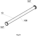
- the rod (13) is configured with the washer with the radial chamfer (107), which passes into cylindrical part (108), which passes into the washer with the radial chamfer (107).
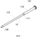
- the guide rod (15) is configured with the spherical head (109), which passes into cylindrical part (110), which via a conical transition (111) passes into cylindrical part (112) with bigger diameter, which passes into the washer with radial chamfer (107).
- the forward grip (4) comprising a body (351) in which a threaded cover (352) and a retainer spring-loaded with a spring of a locking pin (356) are mounted, and configured in the form of a locking pin (353), which is mounted in the body (351), and at the end of the locking pin (353) coming out of the body (351), a locking pin head (354) is mounted, which is fixed with a splint pin of the locking pin (355).
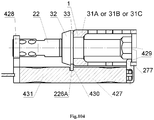
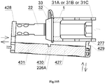
- the caseless semi-automatic weapon (1B) is additionally equipped with a bayonet-knife (427), which contains a front stop with a ring (428), a handle (431) with a slot (430) and a back stop with hook-shaped protrusion (429).
- a bayonet-knife (427) which contains a front stop with a ring (428), a handle (431) with a slot (430) and a back stop with hook-shaped protrusion (429).
- the caseless automatic weapon (1C) is additionally equipped with a bayonet-knife (427), which contains a front stop with a ring (428), a handle (431) with a slot (430) and a back stop with hook-shaped protrusion (429).
- a bayonet-knife (427) which contains a front stop with a ring (428), a handle (431) with a slot (430) and a back stop with hook-shaped protrusion (429).
- the multifunction switch increases the efficiency and accuracy of shooting.
- a container is arranged in the front handle, and the front handle body having two L-shaped ledges with a triangular groove for the wrench for removing or installing the flame arrester compensator and the barrel in field conditions, which has bigger functionality by having the front handle.
- Another claimed feature of the proposed weapon is the possibility to disassemble the magazine, semiautomatic and automatic caseless weapons to pieces to the factory level and then assemble it without any special tools in any conditions.
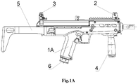
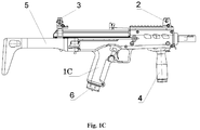
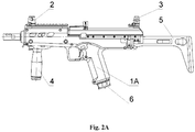
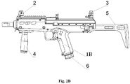
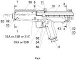
- Figure 4 show a side view of the weapon for magazine shot 1A
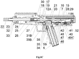
- Figure 6A is a longitudinal section of the weapon 1A
- Figure 7 is a fragment of a longitudinal section of the weapon 1A on the pusher of the magazine latch 35
- Figure 8 is a cross-section 1-1 on Figure 4
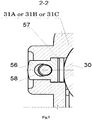
- Figure 9 is a cross-section 2-2 on Figure 5
- Figure 13 is a cross-section 3-3 on Figure 4 of the weapon 1A.
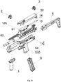
- Figure 15 is a disassembly of the semi-automatic weapon 1B on units (side view). Units comprising: the removable front sight 2, the removable dioptrical sight 3, the forward grip 4, the gunstock 5, the magazine 6, the cover of the receiver with mechanisms 60, the bolt carrier 12A with the bolt 61, the guide rod of a returnable spring 15, the returnable spring 16, the receiver with barrel and mechanisms 62, the trigger housing with mechanisms 63B, the multifunction latch 64.
- Figure 20A is a front view of the bolt carrier 12A
- Figure 21A is a fragment of the rear part of the bolt carrier 12A
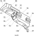
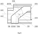
- Figure 22 is a bottom view on the cam slot 96 of the bolt carrier 12A or 12B.
- the bolt carrier 12A comprises the bar 82, the lower part of which has the form of the trapezoidal section 83.
- Enlargement 84 disposed in the rear part of the trapezoidal section 83.
- the guided ledges 86 disposed on the side surface of the bar 82, wherein said guided ledges 86 are configured to interact with the channel guide 178 of the receiver 30.
- the front upper part of the bar 82 shaped in the form of console 87.
- Figure 23 is a side view of the rod 13.
- the rod 13 has the washer with the radial chamfer 107, which passes into the cylindrical part 108, which passes into the washer with the radial chamfer 107.
- Said rod is element of the weapon 1A.
- Figure 23 showing all elements of the rod 13, their forms and interactions.
- Figure 24 is a side view of the guide rod 15.
- the guide rod 15 configured in the form of the spherical head 109, which passes into the cylindrical part 110, which via the conical transition 111 passes into the cylindrical part 112 with bigger diameter, which passes into the washer with the radial chamfer 107.
- Said guide rod is an element of the weapon 1B and 1C. Figure 24 showing all elements of the guide rod 15, their forms and interactions.
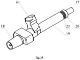
- Figure 25 is a side view of the bolt 61 and Figure 26 is a longitudinal section of the bolt 61.
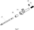
- the bolt 61 comprising: the percussion piston 17, the conical bushing of the bolt 18, shutter housing 19, the safety catch of the firing percussion 20, the spring of the firing percussion 21.
- Figure 27 is a detailing of the bolt 61 (side view). This configuration comprising: the percussion piston 17, the conical bushing of the bolt 18, shutter housing 19, the safety catch of the firing percussion 20, the spring of the firing percussion 21.
- Figure 29 is a side view of the percussion piston 17.
- the percussion piston 17 configured in stepped shaft form.
- the conical section 118 which passes into the cylindrical section with smaller diameter 119 disposed forepart, wherein the inclined ledge 120 disposed at the joint of the conical section 118 and the cylindrical section with smaller diameter 119.
- An angle of the ledge incline d120 to axis of the firing percussion 121 correlates to 30-45 degrees, which is optimal value to ensure peeling force of the ammunition 59 with the threaded bushing 166 of the multifunctional cartridge 26.
- the cylindrical section with smaller diameter 119 passes into the cylindrical section with bigger diameter 122, which passes into the cylindrical piston 123.
- the cylindrical piston 123 passes into the rod section with the grooves 124, wherein the rear groove configured for the safety catch of the firing percussion 20.
- Figure 29 showing all elements of the firing percussion 17, their forms and interactions.
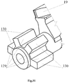
- the stepped ledge is disposed therein, which comprising the base 131 and the leading ledge 132, configured to interact with the cam slot 97 of the bolt carrier 12A or 12B.
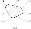
- the leading ledge 132 has rear leading edge 133, side edge of the free running 134 and 135, rear radius chamfers 136, the external sideway forepart scarf 137 and the external radius section 138.
- Two cylindrical grooves with inclined sides 139 disposed on the base 131.
- the base 131 is disposed at angle to the locking lug 129.
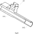
- the glazed area 140 for the conical bushing on the bolt 18 disposed at the end of the cylindrical head 127.
- the central cylindrical channel 141 for the percussion piston 17 disposed within the shutter housing 19.
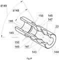
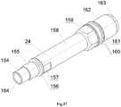
- Figure 34 is a detailing of the receiver with the barrel and mechanisms 62 (side view). This configuration comprising: the balancing gear 22, the spring washer of the balancing gear 23, the barrel 24 with smooth channel, the barrel latch 25, multifunctional cartridge 26, the conical bushing of the receiver 27, the extractor 28, the lock washer of the extractor 29, the receiver 30.
- Figure 36 is a front view of the spring washer of the balancing gear 23.
- the spring washer of the balancing gear 23 configured as the split ring 151 and the three-sided flange 152 on the internal side.
- the spring washer of the balancing gear 23 with their three-sided flange 152 abuts against threaded section 155 for balancing gear 23 when the balancing gear 23 is removed from barrel 24, which allows the balancing gear 23 to not be lost.
- the ends of the split ring 151 have a bias 153.
- the measure of bias T153 correlates 0.2D23, where D23 - is the outer diameter of the spring washer of the balancing gear 23. Said measure is optimal for performing a spring clamp function.
- Figure 36 showing all elements of the spring washer of the balancing gear 23, their forms and interactions.
- Figure 38 is a longitudinal section of the multifunctional cartridge 26.
- the multifunctional cartridge 26 comprising the threaded bushing 165, the internal smooth bushing 166, at least one middle bushing 167 and the external bushing with variable diameter 168, which has bigger diameter 169.
- the threaded bushing 165 and the inner smooth bushing 166 are made of carbide and refractory material.
- the threaded bushing 165 made of carbide and refractory material and has two or more threaded grooves. The pitchs and forms of grooves depends on applying ammunition.
- the bushings 165, 166, 167 and 168 are inserted into each other with tension and created the multifunctional cartridge 26. Outer surface of the bushings 165, 166, 167 and 168 are highly polished.
- the multifunctional cartridge 26 provide high pressure during firing, and high polishing ensures minimal heat loss in the hottest part.
- the polished surface reflecting the heat flux as a thermos.
- the carbide and refractory threaded groove 165, the inner smooth bushing 166 provide high reliability of the weapon during the high temperature of gases produced when the propellant is burnt.
- Figure 38 showing all elements of the spring washer of the multifunctional cartridge 26, their forms and interactions.
- the lower part of the receiver 181 configured in the form of a box-section figure, wherein the cam hole 183 for passage the cocking piece 49A or 49B and the magazine 6 is disposed on the bottom of lower part of the receiver 181.
- the channel guides 178 are fastened to the lower part of the receiver 181 and the barrel chamber 173 via the cap screws 184.
- the stop 185 for the trigger box 31A or 31B or 31C disposed on the rear part of lower part of the receiver 181.
- the stop 185 has the cross through hole 186, which configured to interact with the multifunction latch 64 and two vertical threaded holes 187, wherein said stop is mounted on the rear part of the receiver 181 below via screws 188.
- the rear swivel 189 is disposed on the stop 185.
- the receiver 30 also comprising the bracket 190 having the threaded holes 191 in the lower part for fastening the bracket 190 to the lower part of the receiver 181 and a longitudinal hole 193, which configured to interact with a ramrod 58.
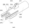
- FIG 43 is a side view of the barrel chamber 173 and Figure 44 is a longitudinal section of the barrel chamber 173.
- the barrel chamber 173 has a cylindrical part 204.
- a multistage cylindrical hole with a threaded section 205 is disposed, which configured to mounting the conical bushing of the receiver 27, to mounting the multifunctional cartridge 26 and to mounting the barrel 24.
- the cross threaded hole 206 is the inlet of the multistage cylindrical hole 205 with threaded section.
- the multistage cylindrical hole with threaded section 205 passes into the cylindrical groove 207, the lower part of which has a threaded hole 208 for the locking screw of the barrel chamber 174.
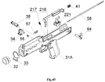
- Figure 47 is a detailing of the trigger housing with mechanisms 63C for automatic weapon 1C.
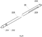
- the trigger housing with mechanisms 63C comprising: the trigger housing 31C, the big front screw 32, the front swivel 33, the magazine the latch 34, the safety catch 38, the trigger bar spring 41, the slide stop 50, the slide stop spring 51, the latch of ramrod 56, the spring of the latch of ramrod 57, the ramrod 58, the multifunction latch 64, the retainer mechanism 217, the firing mechanism for automatic shot 220, the percussion mechanism 222 for semi-automatic and automatic shot.
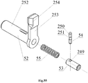
- Figure 51 is a side view of the latch of ramrod 56.
- the latch of ramrod 56 is configured in the form of a plate 233 with rounded ledges 234 on the lower part.
- the through semicircular hole 235 is disposed in the center of the plate 233.
- the semicircular slot 236 is disposed in the lower part of the through hole 235.
- Figure 51 showing all elements of the latch of ramrod 56, their forms and interactions.
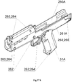
- Figure 57A is a side view of the trigger housing 31A.
- the trigger housing 31A comprising: the right half of the trigger housing 260A and left half of the trigger housing 261A, lower ventilation bushings 262, which additionally function as the hinge for installation a trunnion for a tripod, that provid a precision shoot from a fixed position, cap screws 263, threaded bushings 264 for cap screws 263, threaded bushing with the splineway 265 for cap screw 263 in the gunstock 5 installation place.
- Figure 57B is a side view of the trigger housing 31B.
- the trigger housing 31B comprising: the right half of the trigger housing 260A and left half of the trigger housing 261B, lower ventilation bushings 262, which additionally function as the hinge for installation a trunnion for a tripod, that provid a precision shoot from a fixed position, cap screws 263, threaded bushings 264 for cap screws 263, threaded bushing with the splineway 265 for cap screw 263 in the gunstock 5 installation place.
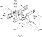
- Figure 58A is a detailing of the trigger housing 31A (side view). This configuration comprising: the right half of the trigger housing 260A and left half of the trigger housing 261A, lower ventilation bushings 262, cap screws 263, threaded bushings 264, threaded bushing with the splineway 265.
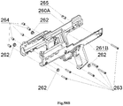
- Figure 58B is a detailing of the trigger housing 31B (side view). This configuration comprising: the right half of the trigger housing 260A and left half of the trigger housing 261B, lower ventilation bushings 262, cap screws 263, threaded bushings 264, threaded bushing with the splineway 265.
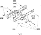
- Figure 58C is a detailing of the trigger housing 31C side view). This configuration comprising: the right half of the trigger housing 260C and left half of the trigger housing 261B, lower ventilation bushings 262, cap screws 263, threaded bushings 264, threaded bushing with the splineway 265.
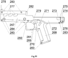
- Figure 59 is a side view of the outside of the left half of the trigger housing 261A or 261B
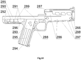
- Figure 60 is a side view of the inside of the left half of the trigger housing 261A or 261B.
- the threaded hole 266 for the big front nut 32 and the handguard 267 are disposed in the front part of the left half of the trigger housing 261A or 261B.
- the left half of the trigger housing 261A or 261B having the pistol grip 268 below in the middle.
- the rectangular hole 269 for the safety catch 38 and hole 270 for the magazine latch 34 are disposed in the pistol grip 268.
- the "T" shaped hole 271 for the slide stop 50 (only for the left half of the trigger housing 261B) is disposed on the pistol grip 268 .
- Slots 273, 274, which biasing with the inclined area 275 and complex-shaped hole 276 for the multifunction latch 64 are disposed in the rear part of the left half of the trigger housing 261A or 261B.
- Ventilative holes 277 and hook 278 for retention the front sight Picatinny-type rail 199 are disposed on the upper front part of the left half of the trigger housing 261A or 261B.
- the trigger guard 279 is disposed above the pistol grip 268 for the safety catch 38 protection, for the case of the weapon dropping.
- the pistol grip 268 and handguard 267 are fastened via the trigger guard 280, on which protrusions are mounted for magazine latch 34 for protection from accidental press.
- the cavity 291 for the cocking piece 49A or 49B is disposed at the beginning of the cavity 290.
- the cavity 292 configured for the stop 185.
- the rectangular hole 293, inlet conical hole 294, and slots for collecting dirt 295 are configured for the magazine 6.
- the hole 296 is configured for the cocking indicator, trigger 49A or 49B.
- the lower rectangular holes 297 and cylindrical hole 298 are configured for mounting the forward grip 4.
- Figure 61 is an exterior side view of the right half of the trigger housing 260A or 260C and Figure 62 is an interior side view inside of the right half of the trigger housing 260A or 260C.
- the right half of the trigger housing 260A or 260C having threaded hole 266 for the big front nut 32 and handguard 267 in the front part.
- the left half of the trigger housing 261A or 261B having the pistol grip 268 below in the middle.
- the pistol grip 268 having the rectangular hole 269 for safety catch 38 and the complex-shaped hole 299 for the magazine latch 34.
- the hole 301 for the multifunction latch 64 is disposed in the rear part 300 of the right half of the trigger housing 260A or 260C.
- Cross threaded holes 302 for the threaded bushings 264 and threaded bushing with the splineway 265 are disposed on the right half of the trigger housing 260A or 260C.
- the holes 284 for the lower ventilation grooves 262 disposed in the side walls of the handguard 267.
- the channel 285, cavity 286 and slot 287 for installation the receiver with the barrel and mechanisms 62 are disposed within the right half of the trigger housing 260A or 260C.
- the assembly holes 303 for the safety latch 37, safety spring retaining pin 36, magazine latch pusher 35 are disposed upper the pistol grip 268.
- the cavity 288 is configured for the magazine latch 34 as well.
- the cavity 289 is configured for hauling with the hook 39A or 39B and the cavity 290 is configured for the trigger bar spring 41.
- the cavity 291 for the cocking piece 49A or 49B is disposed at the beginning of the cavity 290.
- the rectangular hole 293, inlet conical hole 294, and slots for collecting dirt 295 are configured for the magazine 6.
- the protrusion 304 with the cross hole 305 for the latch of the ramrod 56 and the longitudinal hole 306 for the ramrod 58 are disposed outside on the handguard 267 near the trigger guard 280.
- the through groove 307 is configured for the multifunction latch 43 (only for the right half of the trigger housing 260C).
- the lower rectangular holes 297 and the cylindrical hole 298 are configured for fastening the front handle 4.
- the "T" shaped slot 308 for mounting the gunstock 5 is disposed in the rear part 300 of the right half of the trigger housing 260A or 260C.
- the slot 309 for the spring of the ramrod latch 57 is disposed at the beginning of the cavity 286.
- Figure 61 , Figure 62 showing all elements of the right half of the trigger housing 260A or 260C, their forms and interactions.
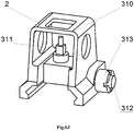
- Figure 64 is a detailing of the adjustable front sight 2 (side view). This configuration comprising: the front sight bracket 310, front sight 311, cap screw 312 and cylindrical nut 313 with the splineway for a screwdriver.
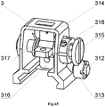
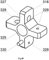
- Figure 68 is side view of the impeller with the diopter holes 316.
- the impeller with the diopter holes 316 having the blades 327 with the diopter holes 328 with the through axial hole 329.
- the retainer pin 330 is disposed on one of the impeller blades 327.
- Figure 68 showing all elements of the impeller with the diopter holes 316, their forms and interactions.
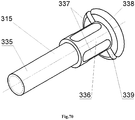
- Figure 69 is a side view of the front sight 311.
- the front sight 311 having the cylindrical section with the thread 331, which passes into a prismatic section 332, which passes into the cylindrical section 333.
- the through slot 334 is disposed in the cylindrical section with the thread 331.
- Figure 69 showing all elements of the front sight 311, their forms and interactions.
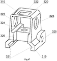
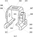
- Threaded hole 347 for the retainer screw 318 is disposed in the cylindrical protrusion 343 on the side surface of the protrusion for the thickness of the wall.
- Cross hole 349 for the adjustment screw 312 disposed in front on the side surface of the plate 340.
- the through longitudinal slot 350 is disposed in front of the wall of the clamp 341 on the entire wall thickness of the plate 340. Because of the through longitudinal slot 350 the front sight bracket 314 works as a spring clip that ensures reliable retention of the front sight bracket 314 to the front sight rail 199.
- Figure 71 showing all elements of the bracket 314, their forms and interactions.
- Figure 72 is a side view of the forward grip 4.
- the forward grip 4 comprising: the body 351 with mounted threaded cover 352 and the retainer spring-loaded by the spring of the locking pin 356 and configured in the form of the locking pin 353, which is mounted in the body 351, the locking pin head 354 is fixed via splint pin of the locking pin 355 is mounted at the end of the locking pin 353 that comes out of the body 351 .
- Figure 73 is a detailing of the forward grip 4 (side view). This configuration comprising: the body 351, threaded cover 352, locking pin 353, locking pin head 354, splint pin of locking pin 355, spring of the locking pin 356.
- Figure 74 is a side view of the body 351.
- the body 351 having the plate 357.
- the holes 358, 359 for locking pin 353 and for spring of the locking pin 356 are disposed in front of the plate 357.
- the rear end of the plate 357 connected to the conical cylindrical part 360, inside of which the cavity 361 with thread 362 at the output for the threaded cover 352 is disposed thereon.
- Two "L" shaped protrusions 363, 364 with the slot 365 disposed on the upper surface in the middle of the plate 357.
- the body used as a wrench for the balancing gear 22 and barrel 24.
- Figure 75 showing all elements of the forward grip body 351 their forms and interactions.
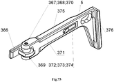
- FIG 75 is a side view of the gunstock 5.
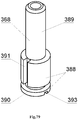
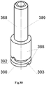
- the gunstock 5 comprising: the bracket of the gunstock 366 having the bushing of the gunstock axis 367, in which the gunstock of the axis 368 spring-loaded with the spring of the gunstock axis 370 and fixed via pin of the gunstock axis 369 in the gunstock base 371 is mounted, the adjustment lever 372 is configured to swing on the axis of the adjustment lever 373 and interact with the gunstock body 375, the smooth recoil pad 376.
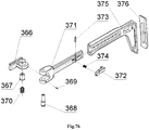
- Figure 76 is a detailing of the gunstock 5 (side view). This configuration comprising: the bracket of the gunstock 366, the bushing of the gunstock axis 367, the gunstock of the axis 368, the pin of the gunstock axis 369, the spring of the gunstock axis 370, the gunstock base 371, the adjustment lever 372, the axis of the adjustment lever 373, the spring of the adjustment lever 374, the gunstock body 375, the smooth recoil pad 376.
- the gunstock body 375 is put on the base of the gunstock 371 and configured to reciprocate along the base of the gunstock 371 and the smooth recoil pad 376 disposed in the gunstock body 375.
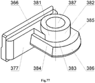
- Figure 77 is a front view of the bracket of the gunstock 366 and Figure 78 is a rear view of the bracket of the gunstock 366.
- the gunstock bracket 366 is configured in the form of "T" shaped section 377 with inclined slot 378, blind hole 379 for the multifunction latch 64 and with the locking protrusion 380.
- the complex-shaped protrusion 381 is disposed in the upper part on the other side of the "T" shaped section 377 in the form of the cylinder 382 and in the lower part in the form of the protrusion 383 with inclined sides 384, horizontal platform 385 and radius side 386.
- the through hole 387 for the gunstock of the axis 368 is disposed in the protrusion 381.
- Figure 77 , Figure 78 showing all elements of the bracket of the gunstock 366, their forms and interactions.
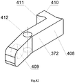
- Figure 82 is a side view of the adjustment lever 372.
- the gunstock adjustment lever 372 is configured in the form of the lever 408 with blind hole 409 on one side for the spring of adjustment lever 374.
- the protrusion 410 with the inclined surface 411 disposed on the other side of the lever 408.
- Through hole 412 for the axis of the adjustment lever 373 is disposed in the middle of the lever 408.
- Figure 82 showing all elements of the adjustment lever 372, their forms and interactions.
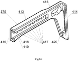
- Figure 83 is a side view of the gunstock body 375.
- the body of the gunstock 375 is configured in the form of the plate 413 with protrusion 414 in the form of a plate, which corresponds with the form of the smooth recoil pad 376.
- the guide "T" shaped blind slot 416 disposed in front of said plate 413 and configured to connect the gunstock body 375 with the gunstock base 371.
- Cross grooves 417 for the adjustment lever 372 are disposed in the guide "T” shaped blind slot 416.
- the first cross groove 417 configured with the chamfer 418 having negative incline 419.
- the rectangular hole 420 disposed in the protrusion 414 for the smooth recoil pad 376.
- Figure 83 showing all elements of the gunstock body 375, their forms and interactions.
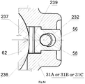
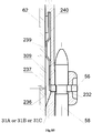
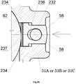
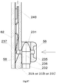
- Figure 86 is a fragment of a cross section of the latch of the ramrod 56 and Figure 87 is a fragment of a longitudinal section of the latch of the ramrod 56. Said figures are showing operation of the latch of the ramrod 56 in the on position. If the ramrod 58 is to be removed, press the latch of the ramrod 56. The front end of the flat spring 237 presses against the receiver with the barrel and mechanisms 62, and the semi-circular slot 236 comes out of the groove 232 of the ramrod 58, while the groove 232 will be located opposite the through semi-circular hole 235, which allows to remove the ramrod 58.
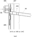
- Figure 88 is disassembly and assembly of the latch of the ramrod 56. If the the latch of the ramrod 56 is to be disassembled, press and hold the latch of the ramrod 56, which will press on the front end of the flat spring 237 and brings it out of the cavity 309 of the trigger housing 31A or 31B or 31C. At the same time, the ramrod 58 is inserted into the through hole 238 of the flat spring 237 and pushes the rear part 240 of the flat spring 237 out of the cavity 309 of the trigger housing 31A or 31B or 31C. At this point, the latch of the ramrod 56 is being disassembled without special tools. If the latch of the ramrod 56 is to be assembled, follow these steps in the reverse order.
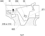
- Figure 89 is showing operation of the slide stop 50 in the off position (side view).
- the slide stop spring 51 pushes against the lever 242 of the slide stop 50.
- the slide stop 50 rotates relative to the hinge 243 and rests against the lower protrusion 246 on section 421, which is located in the cavity 422 of the trigger housing 31B or 31C.
- the plate 241 of the slide stop 50 tightly closes the cavity 422 in the trigger housing 31B or 31C and the cam through hole 271 of the trigger housing 31B or 31C and prevents the water, dirt, dust and sand entering weapons 1A or 1B. All the above mentioned provides reliable operation of the slide stop 50 and weapon 1A or 1B in general.
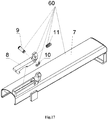
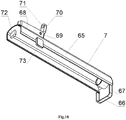
- Figure 92 showing an operation of the receiver cover 7 for the manual rearward movement.
- the bolt carrier 12A or 12B with the bolt 61, the returnable spring 16 and the guide rod of the recoil spring 15 are moved rearward, while the front stop 72 of the receiver cover 7 presses against the support platform 96 of the bolt 12A or 12B.
- enlargement 84 of the bolt carrier 12A or 12B cocks the cocking piece 49C.
- the returnable spring 16 is not involved in the reloading weapons 1B or 1C, thereby reducing the cocking force of weapons and allows to stop the cover of the receiver 7 in any position. This provides convenient access and elimination of light delays when using weapons 1B or 1C in combat conditions.
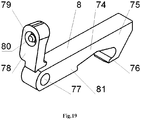
- FIG 93 showing an operation of the cocking lever 8 in the off position.
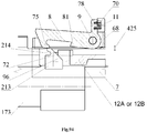
- the hook 75 of the cocking lever 8 extends beyond the inclined protrusion 213 of the barrel chamber 173 and forms a contact pad in the cylindrical slot 214.
- the inclined protrusion 81 of the cocking lever 8 creates the gap 425 with the bolt carrier of 12A or 12B.
- the cocking lever 8 rotates on the axis of the cocking lever 9 and being pressed by the spring of the cocking lever 11.
- the gap 426 is made between the support platform 96 of the bolt carrier 12A or 12B and the front stop 72 of the receiver cover 7.
- the receiver cover 7 remains stationary and does not have holes.
- Figure 94 showing an operation of the cocking lever 8 in the on position.
- the button 70 of the bracket 68 of the receiver cover 7 and the button 78 of the cocking lever 8 are pressed together.
- the cocking lever 8 rotates on the axis of the cocking lever 9 and the spring of the cocking lever 11 contracts, and the cocking lever 8 is fixed in the on position.
- the hook 75 of the cocking lever 8 extends from the cylindrical slot 214 of the inclined protrusion 213 of the barrel chamber 173.
- the gap 425 between the inclined protrusion 81 of the cocking lever 8 and the bolt carrier 12A or 12B increases.
- the support platform 96 of the slide frame 12A or 12B rests against the front stop 72 of the receiver cover 7.
- Figure 95 showing an operation of the cocking lever 8 for the forward movement.
- the button 70 of the bracket 68 of the receiver cover 7 is pushed forward without using button 78 of the cocking lever 8.
- the inclined protrusion 81 presses against the protrusion 88 of the bolt carrier 12A or 12B, which forces the bolt 61 to forcibly deliver the caseless ammunition 59, including contaminated, from the magazine 6 to the multifunctional cartridge 26.
- This increases the reliability of weapons 1A or 1B or 1C in combat conditions.
- the gap 426 is formed between the front stop 72 of the cover of the receiver 7 and the stop plate 96 of the slide frame 12A or 12B.
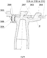
- FIG 96 Figure 97 showing assembly and disassembly of the forward grip 4 for the weapon 1A or 1B or 1C.
- the "L" shaped protrusions 363, 364 of the forward grip 4 are set against the lower rectangular holes 297 of the trigger housing 31A or 31B or 31C and press the front handle 4 up to the stop into the trigger housing 31A or 31B or 31C. Then the front handle 4 moves in the direction of the trigger guard 280, while the locking pin 353 of the forward grip 4 engaging with the cylindrical hole 298 of the trigger housing 31A or 31B or 31C.
- forward grip 4 If the forward grip 4 is to be disassemble it is needed to pull on the head of the locking pin 354, wherein said locking pin 353 of the forward grip 4 releases from the engagement with the cylindrical bore 298 of the trigger housing 31A or 31B or 31C, and then to perform the steps reverse to the installation. Easy assembly and disassembly of the forward grip 4 allow to change the configuration of the weapon 1A or 1B or 1C without special tools in any conditions.
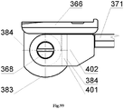
- FIG 98 Figure 99 showing a folding and unfolding of the gunstock 5 for the weapon 1A or 1B or 1C.
- push up the gunstock base 371 and the rectangular slot 402 of the gunstock base 371 coincide with the protrusion 383 of the gunstock bracket 366 and, without releasing it, rotate it at 180 degrees.
- the axis of the gunstock 368 in the gunstock bracket 366 compresses the spring of the gunstock axis 370.
- the gunstock base 371 should be released.
- the inclined platform 401 of the gunstock base 371 engages the gunstock side 384 of the gunstock bracket 366 and fixes the gunstock 5 in this position.
- the inclined platform 401 of the gunstock base 371 and the inclined side 384 of the gunstock bracket 366 are always spring-loaded with the spring of the gunstock axis 370. Due to this, the select of the gap between these sections occurs without assistance and during long-term operation the reliability of the gunstock 5 increases. Fast folding and unfolding of the gunstock 5 allow to change the length of weapons at any time.
- Figure 100 Figure 101 showing an alteration to the length of the gunstock 5 for the weapon 1A or 1B or 1C.
- the spring of the adjustment lever 374 of the gunstock base 371 presses the adjustment lever 372 of the gunstock base 371 and the protrusion 410 with inclined plane 411 of the adjustment lever 372 and said spring 374 enters the transverse grooves 417 of the gunstock body 375.
- the protrusion 410 of the adjustment lever 372 is fixed in the corresponding new transverse groove 417 of the gunstock body 375.
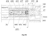
- FIG 106 showing an operation of the weapon 1A in the lock time for the magazine firing.
- the lock time 432 lasts from the beginning of an ignition of the propellant 433 (solid, liquid, gaseous) to the beginning of the piercing of the projectile 434 into the notches of the multifunctional cartridge 26. During this period the following processes occur:
- FIG 107 showing an operation of the weapon 1B and 1C in the lock time for the semi-automatic shot and automatic shot.
- the lock time 432 lasts from the beginning of the ignition of the propellant 433 (solid, liquid, gaseous) to a beginning of the gripping of the projectile 434 into the notches of the multifunctional cartridge 26.
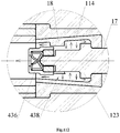
- the following processes occur: after striking the cocking piece 49B on the percussion piston 17, the percussion piston 17 breaks the primer with anvil 435 inside the igniter block 436 and the force flame 437 ignites the propellant 433 (solid, liquid, gaseous). Gases 438 begin to be exhausted with high temperature and pressure. Wherein said igniter block 436 under the action of gases 438 presses on the percussion piston 17.
- the percussion piston 17 moves and selects the gap 443 formed between the cylindrical piston 123 of the percussion piston 17 and the internal surface of the stout wall 116 of the conical bushing of the bolt 18.
- the thickness T443 of the gap 443 depends on many quantities and is set by calculation in each specific case, while the next condition, that the received impulse I should be sufficient for the operation of the weapon's automation is followed.
- the cylindrical piston 123 of the percussion piston 17 under the action of gases 438 will press the conical bushing of the bolt 18 to the glazed area 140 of the shutter housing 19, thereby blocking the leakage of gases 438 into the receiver 30.
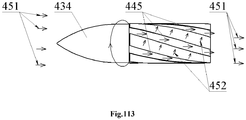
- FIG 111 , Figure 112 , Figure 113 showing an operation of the weapon in the transitional period 450.
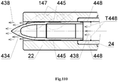
- the transitional period 450 lasts from the moment when the projectile 434 reached the inclined holes 147 of the balancing gear 22 until the gases 438 stop to exert force on the projectile 434. During this period, the following process occurs: The gases 438 passes through the inclined holes 147 of the balancing gear 22 to the outside. The projectile 434 reaches a higher initial velocity Vmax near twenty centimeters from the face of the muzzle of the balancing gear 22.
- the transitional period 450 ends when the gas pressure 438 on the projectile 434 is balanced with atmospheric pressure.
- the claimed new weapon easily adapts to the various types of weapons (pistol, submachine gun, assault rifle, light machine gun, medium machine gun), can be applied for the army, police, hunting, sport and works with maximum efficiency.
Landscapes
- Engineering & Computer Science (AREA)
- General Engineering & Computer Science (AREA)
- Physics & Mathematics (AREA)
- Optics & Photonics (AREA)
- Catching Or Destruction (AREA)
- Mutual Connection Of Rods And Tubes (AREA)
- Portable Nailing Machines And Staplers (AREA)
- Aiming, Guidance, Guns With A Light Source, Armor, Camouflage, And Targets (AREA)
Applications Claiming Priority (2)
| Application Number | Priority Date | Filing Date | Title |
|---|---|---|---|
| UAA201709150A UA120290C2 (uk) | 2017-09-18 | 2017-09-18 | Безгільзова зброя (варіанти) |
| PCT/UA2017/000093 WO2019054975A1 (ru) | 2017-09-18 | 2017-09-28 | Безгильзовое оружие (варианты) |
Publications (3)
| Publication Number | Publication Date |
|---|---|
| EP3686545A1 true EP3686545A1 (de) | 2020-07-29 |
| EP3686545A4 EP3686545A4 (de) | 2021-07-14 |
| EP3686545B1 EP3686545B1 (de) | 2025-06-18 |
Family
ID=65723408
Family Applications (1)
| Application Number | Title | Priority Date | Filing Date |
|---|---|---|---|
| EP17925445.3A Active EP3686545B1 (de) | 2017-09-18 | 2017-09-28 | Varianten hülsenloser waffe |
Country Status (5)
| Country | Link |
|---|---|
| US (1) | US10948250B2 (de) |
| EP (1) | EP3686545B1 (de) |
| IL (1) | IL273357B2 (de) |
| UA (1) | UA120290C2 (de) |
| WO (1) | WO2019054975A1 (de) |
Families Citing this family (10)
| Publication number | Priority date | Publication date | Assignee | Title |
|---|---|---|---|---|
| UA119994C2 (uk) * | 2017-05-15 | 2019-09-10 | Олексій Олександрович Шарков | Безгільзовий боєприпас для вогнепальної зброї і механізм для екстракції безгільзових боєприпасів |
| UA120290C2 (uk) * | 2017-09-18 | 2019-11-11 | Георгій Георгійович Макаров | Безгільзова зброя (варіанти) |
| UA124985C2 (uk) | 2019-08-20 | 2021-12-22 | Георгій Георгійович Макаров | Безгільзова магазинна зброя (варіанти) |
| USD982116S1 (en) * | 2019-09-24 | 2023-03-28 | Karl Taylor | AK rifle rear trunnion |
| USD911482S1 (en) * | 2019-09-24 | 2021-02-23 | Karl Taylor | AK rifle rear trunnion |
| US11959719B2 (en) * | 2020-03-05 | 2024-04-16 | Vojtech Dvorak | Pneumatic simulator apparatus for an open bolt automatic firearm |
| US11187492B2 (en) * | 2020-04-18 | 2021-11-30 | Henry Hanson Mumford | Modular compact firearm system |
| CN115060111B (zh) * | 2022-06-16 | 2024-02-20 | 深圳市鑫创达安全设备制造有限公司 | 应用于手枪的战术扩展系统 |
| USD1118805S1 (en) | 2023-08-16 | 2026-03-17 | Imi Defense Ltd | Grip module |
| CN119777830A (zh) * | 2025-03-10 | 2025-04-08 | 成都理工大学 | 一种小尺寸智能牵引系统及其控制方法 |
Family Cites Families (18)
| Publication number | Priority date | Publication date | Assignee | Title |
|---|---|---|---|---|
| US3474560A (en) * | 1968-04-04 | 1969-10-28 | Olin Mathieson | Caseless cartridge chamber-sleeve ejector and binary feed system |
| US3722123A (en) * | 1971-08-25 | 1973-03-27 | Olin Corp | Caseless ammunition firing system |
| US4123963A (en) * | 1977-05-11 | 1978-11-07 | Junker Ralph D | Firearm and caseless ammunition therefor |
| IT1190066B (it) * | 1986-02-28 | 1988-02-10 | Fiocchi Spa Giulio | Arma con otturatore perfezionato,per munzioni senza bossolo |
| AT396299B (de) * | 1991-03-14 | 1993-07-26 | Pse Prod & Systementwicklung | Handfeuerwaffe, insbesondere jagdwaffe |
| GB9223325D0 (en) * | 1992-11-06 | 1992-12-23 | Datestyle Ltd | A vortices-activated muzzle stabiliser for a gun |
| RU2122170C1 (ru) | 1997-09-18 | 1998-11-20 | Цветков Сергей Аркадьевич | Система автоматического безгильзового оружия |
| RU2193743C2 (ru) * | 1999-10-11 | 2002-11-27 | Горянин Владимир Николаевич | Динамический дульный тормоз |
| DE102004025564B3 (de) * | 2004-05-25 | 2005-10-06 | Heckler & Koch Gmbh | Anordnung aus einem Verschluß und einem die Treib- und Zündladung umschließenden Geschoß |
| US8359964B2 (en) | 2008-05-30 | 2013-01-29 | Diehl Bgt Defence Gmbh & Co. Kg | Weapon system with caseless ammunition |
| TWM396954U (en) * | 2010-06-11 | 2011-01-21 | Univ China Sci & Tech | Tactics handgrip for assault rifle |
| RU2637082C2 (ru) * | 2011-01-14 | 2017-11-29 | АРМВЕСТ, ЭлЭлСи | Огнестрельное оружие с быстрой сменой ствола |
| RU2478177C2 (ru) | 2011-03-29 | 2013-03-27 | Государственное унитарное предприятие "Конструкторское бюро приборостроения" | Автоматическое стрелковое оружие |
| US8863421B1 (en) * | 2011-10-26 | 2014-10-21 | John Wadie Farage | Caseless ammunition firing system and device |
| RU2549599C1 (ru) * | 2013-10-21 | 2015-04-27 | Владимир Михайлович Палецких | Безгильзовое оружие |
| RU2573866C2 (ru) * | 2014-02-14 | 2016-01-27 | Максим Александрович Филиппов | Регулируемое дульное устройство |
| UA119994C2 (uk) * | 2017-05-15 | 2019-09-10 | Олексій Олександрович Шарков | Безгільзовий боєприпас для вогнепальної зброї і механізм для екстракції безгільзових боєприпасів |
| UA120290C2 (uk) * | 2017-09-18 | 2019-11-11 | Георгій Георгійович Макаров | Безгільзова зброя (варіанти) |
-
2017
- 2017-09-18 UA UAA201709150A patent/UA120290C2/uk unknown
- 2017-09-28 EP EP17925445.3A patent/EP3686545B1/de active Active
- 2017-09-28 WO PCT/UA2017/000093 patent/WO2019054975A1/ru not_active Ceased
- 2017-09-28 US US16/648,125 patent/US10948250B2/en active Active
- 2017-09-28 IL IL273357A patent/IL273357B2/en unknown
Also Published As
| Publication number | Publication date |
|---|---|
| US20200232731A1 (en) | 2020-07-23 |
| IL273357A (en) | 2020-05-31 |
| UA120290C2 (uk) | 2019-11-11 |
| EP3686545B1 (de) | 2025-06-18 |
| EP3686545A4 (de) | 2021-07-14 |
| IL273357B2 (en) | 2024-05-01 |
| IL273357B1 (en) | 2024-01-01 |
| US10948250B2 (en) | 2021-03-16 |
| WO2019054975A1 (ru) | 2019-03-21 |
Similar Documents
| Publication | Publication Date | Title |
|---|---|---|
| EP3686545B1 (de) | Varianten hülsenloser waffe | |
| US11768045B2 (en) | Caseless magazine weapon (variants) | |
| RU2637082C2 (ru) | Огнестрельное оружие с быстрой сменой ствола | |
| US5983774A (en) | Machine gun | |
| US8820212B2 (en) | Urban combat system automatic firearm having ammunition feed controlled by weapon cycle | |
| US8281699B2 (en) | Firearm with enhanced recoil and control characteristics | |
| US7877919B2 (en) | Muzzleloader firearm system | |
| US7735409B1 (en) | Conversion kit and method for a RUGER® 10/22® semi-automatic .22 caliber rim fire gun to shoot .17 mach 2 cartridges | |
| US6374720B1 (en) | Firearm with an expansion chamber with variable volume | |
| US11543204B2 (en) | Handgun compensator | |
| KR20000010863A (ko) | 발사 속도 조절 기구 | |
| US5689908A (en) | Rifle construction with swing-type barrel | |
| US20250123073A1 (en) | Modular firearm and components thereof | |
| US7726058B2 (en) | Muzzleloader firearm with quick-release breech plug | |
| RU2214576C1 (ru) | Ручное огнестрельное оружие револьверного типа | |
| RU2736305C1 (ru) | Способ уменьшения усилия отдачи огнестрельного оружия и пушка с откидным патронником для его реализации. варианты | |
| RU2561181C2 (ru) | Стрелковое оружие без эффекта "отдачи" | |
| US20070137085A1 (en) | Safety cartridge | |
| RU2483266C2 (ru) | Устройство карабина револьверного автоматического безгильзового с горизонтальным отъемным коробчатым магазином | |
| RU2422752C2 (ru) | Автомат | |
| RU2776331C1 (ru) | Пистолет-пулемет | |
| RU2295101C2 (ru) | Способ работы автоматики стрелково-пушечного оружия и устройство для его осуществления | |
| TR2024004680A2 (tr) | 5.7×28 kali̇bre bi̇r maki̇neli̇ si̇lah | |
| RU207692U1 (ru) | Безоткатное многозарядное оружие без обратного скольжения с магазинным питанием | |
| WO2026052998A1 (ru) | Безгильзовое болтовое оружие |
Legal Events
| Date | Code | Title | Description |
|---|---|---|---|
| STAA | Information on the status of an ep patent application or granted ep patent |
Free format text: STATUS: THE INTERNATIONAL PUBLICATION HAS BEEN MADE |
|
| PUAI | Public reference made under article 153(3) epc to a published international application that has entered the european phase |
Free format text: ORIGINAL CODE: 0009012 |
|
| STAA | Information on the status of an ep patent application or granted ep patent |
Free format text: STATUS: REQUEST FOR EXAMINATION WAS MADE |
|
| 17P | Request for examination filed |
Effective date: 20200418 |
|
| AK | Designated contracting states |
Kind code of ref document: A1 Designated state(s): AL AT BE BG CH CY CZ DE DK EE ES FI FR GB GR HR HU IE IS IT LI LT LU LV MC MK MT NL NO PL PT RO RS SE SI SK SM TR |
|
| AX | Request for extension of the european patent |
Extension state: BA ME |
|
| DAV | Request for validation of the european patent (deleted) | ||
| DAX | Request for extension of the european patent (deleted) | ||
| A4 | Supplementary search report drawn up and despatched |
Effective date: 20210615 |
|
| RIC1 | Information provided on ipc code assigned before grant |
Ipc: F41C 7/00 20060101AFI20210609BHEP Ipc: F41A 3/00 20060101ALI20210609BHEP Ipc: F41A 21/00 20060101ALI20210609BHEP Ipc: F41A 11/00 20060101ALI20210609BHEP Ipc: F41A 19/00 20060101ALI20210609BHEP Ipc: F41A 15/00 20060101ALI20210609BHEP Ipc: F41A 17/00 20060101ALI20210609BHEP Ipc: F41G 1/06 20060101ALI20210609BHEP Ipc: F41C 23/20 20060101ALI20210609BHEP Ipc: F42B 5/18 20060101ALI20210609BHEP Ipc: F41A 3/20 20060101ALI20210609BHEP Ipc: F41A 3/26 20060101ALI20210609BHEP Ipc: F41A 15/16 20060101ALI20210609BHEP Ipc: F41A 15/20 20060101ALI20210609BHEP Ipc: F41A 19/43 20060101ALI20210609BHEP Ipc: F41A 21/12 20060101ALI20210609BHEP Ipc: F41A 21/36 20060101ALI20210609BHEP Ipc: F41C 23/14 20060101ALI20210609BHEP Ipc: F41C 23/16 20060101ALI20210609BHEP Ipc: F41G 1/30 20060101ALI20210609BHEP Ipc: F42B 5/10 20060101ALI20210609BHEP |
|
| STAA | Information on the status of an ep patent application or granted ep patent |
Free format text: STATUS: EXAMINATION IS IN PROGRESS |
|
| 17Q | First examination report despatched |
Effective date: 20240417 |
|
| GRAP | Despatch of communication of intention to grant a patent |
Free format text: ORIGINAL CODE: EPIDOSNIGR1 |
|
| STAA | Information on the status of an ep patent application or granted ep patent |
Free format text: STATUS: GRANT OF PATENT IS INTENDED |
|
| INTG | Intention to grant announced |
Effective date: 20250117 |
|
| GRAS | Grant fee paid |
Free format text: ORIGINAL CODE: EPIDOSNIGR3 |
|
| GRAA | (expected) grant |
Free format text: ORIGINAL CODE: 0009210 |
|
| STAA | Information on the status of an ep patent application or granted ep patent |
Free format text: STATUS: THE PATENT HAS BEEN GRANTED |
|
| AK | Designated contracting states |
Kind code of ref document: B1 Designated state(s): AL AT BE BG CH CY CZ DE DK EE ES FI FR GB GR HR HU IE IS IT LI LT LU LV MC MK MT NL NO PL PT RO RS SE SI SK SM TR |
|
| REG | Reference to a national code |
Ref country code: GB Ref legal event code: FG4D |
|
| REG | Reference to a national code |
Ref country code: CH Ref legal event code: EP |
|
| REG | Reference to a national code |
Ref country code: DE Ref legal event code: R096 Ref document number: 602017090079 Country of ref document: DE |
|
| REG | Reference to a national code |
Ref country code: CH Ref legal event code: EP |
|
| REG | Reference to a national code |
Ref country code: IE Ref legal event code: FG4D |
|
| PG25 | Lapsed in a contracting state [announced via postgrant information from national office to epo] |
Ref country code: FI Free format text: LAPSE BECAUSE OF FAILURE TO SUBMIT A TRANSLATION OF THE DESCRIPTION OR TO PAY THE FEE WITHIN THE PRESCRIBED TIME-LIMIT Effective date: 20250618 |
|
| PGFP | Annual fee paid to national office [announced via postgrant information from national office to epo] |
Ref country code: DE Payment date: 20250915 Year of fee payment: 9 |
|
| REG | Reference to a national code |
Ref country code: LT Ref legal event code: MG9D |
|
| PG25 | Lapsed in a contracting state [announced via postgrant information from national office to epo] |
Ref country code: GR Free format text: LAPSE BECAUSE OF FAILURE TO SUBMIT A TRANSLATION OF THE DESCRIPTION OR TO PAY THE FEE WITHIN THE PRESCRIBED TIME-LIMIT Effective date: 20250919 Ref country code: NO Free format text: LAPSE BECAUSE OF FAILURE TO SUBMIT A TRANSLATION OF THE DESCRIPTION OR TO PAY THE FEE WITHIN THE PRESCRIBED TIME-LIMIT Effective date: 20250918 |
|
| PG25 | Lapsed in a contracting state [announced via postgrant information from national office to epo] |
Ref country code: BG Free format text: LAPSE BECAUSE OF FAILURE TO SUBMIT A TRANSLATION OF THE DESCRIPTION OR TO PAY THE FEE WITHIN THE PRESCRIBED TIME-LIMIT Effective date: 20250618 |
|
| PGFP | Annual fee paid to national office [announced via postgrant information from national office to epo] |
Ref country code: BE Payment date: 20250915 Year of fee payment: 9 Ref country code: GB Payment date: 20250915 Year of fee payment: 9 |
|
| PG25 | Lapsed in a contracting state [announced via postgrant information from national office to epo] |
Ref country code: HR Free format text: LAPSE BECAUSE OF FAILURE TO SUBMIT A TRANSLATION OF THE DESCRIPTION OR TO PAY THE FEE WITHIN THE PRESCRIBED TIME-LIMIT Effective date: 20250618 |
|
| PGFP | Annual fee paid to national office [announced via postgrant information from national office to epo] |
Ref country code: FR Payment date: 20250915 Year of fee payment: 9 |
|
| PG25 | Lapsed in a contracting state [announced via postgrant information from national office to epo] |
Ref country code: RS Free format text: LAPSE BECAUSE OF FAILURE TO SUBMIT A TRANSLATION OF THE DESCRIPTION OR TO PAY THE FEE WITHIN THE PRESCRIBED TIME-LIMIT Effective date: 20250918 |
|
| PGFP | Annual fee paid to national office [announced via postgrant information from national office to epo] |
Ref country code: CZ Payment date: 20250915 Year of fee payment: 9 |
|
| REG | Reference to a national code |
Ref country code: NL Ref legal event code: MP Effective date: 20250618 |
|
| PGFP | Annual fee paid to national office [announced via postgrant information from national office to epo] |
Ref country code: LV Payment date: 20250915 Year of fee payment: 9 |
|
| PG25 | Lapsed in a contracting state [announced via postgrant information from national office to epo] |
Ref country code: NL Free format text: LAPSE BECAUSE OF FAILURE TO SUBMIT A TRANSLATION OF THE DESCRIPTION OR TO PAY THE FEE WITHIN THE PRESCRIBED TIME-LIMIT Effective date: 20250618 |
|
| PG25 | Lapsed in a contracting state [announced via postgrant information from national office to epo] |
Ref country code: PT Free format text: LAPSE BECAUSE OF FAILURE TO SUBMIT A TRANSLATION OF THE DESCRIPTION OR TO PAY THE FEE WITHIN THE PRESCRIBED TIME-LIMIT Effective date: 20251020 |
|
| REG | Reference to a national code |
Ref country code: AT Ref legal event code: MK05 Ref document number: 1804515 Country of ref document: AT Kind code of ref document: T Effective date: 20250618 |
|
| PG25 | Lapsed in a contracting state [announced via postgrant information from national office to epo] |
Ref country code: IS Free format text: LAPSE BECAUSE OF FAILURE TO SUBMIT A TRANSLATION OF THE DESCRIPTION OR TO PAY THE FEE WITHIN THE PRESCRIBED TIME-LIMIT Effective date: 20251018 |
|
| PG25 | Lapsed in a contracting state [announced via postgrant information from national office to epo] |
Ref country code: AT Free format text: LAPSE BECAUSE OF FAILURE TO SUBMIT A TRANSLATION OF THE DESCRIPTION OR TO PAY THE FEE WITHIN THE PRESCRIBED TIME-LIMIT Effective date: 20250618 Ref country code: SM Free format text: LAPSE BECAUSE OF FAILURE TO SUBMIT A TRANSLATION OF THE DESCRIPTION OR TO PAY THE FEE WITHIN THE PRESCRIBED TIME-LIMIT Effective date: 20250618 |
|
| PG25 | Lapsed in a contracting state [announced via postgrant information from national office to epo] |
Ref country code: PL Free format text: LAPSE BECAUSE OF FAILURE TO SUBMIT A TRANSLATION OF THE DESCRIPTION OR TO PAY THE FEE WITHIN THE PRESCRIBED TIME-LIMIT Effective date: 20250618 |
|
| PG25 | Lapsed in a contracting state [announced via postgrant information from national office to epo] |
Ref country code: EE Free format text: LAPSE BECAUSE OF FAILURE TO SUBMIT A TRANSLATION OF THE DESCRIPTION OR TO PAY THE FEE WITHIN THE PRESCRIBED TIME-LIMIT Effective date: 20250618 |
|
| PG25 | Lapsed in a contracting state [announced via postgrant information from national office to epo] |
Ref country code: RO Free format text: LAPSE BECAUSE OF FAILURE TO SUBMIT A TRANSLATION OF THE DESCRIPTION OR TO PAY THE FEE WITHIN THE PRESCRIBED TIME-LIMIT Effective date: 20250618 Ref country code: SK Free format text: LAPSE BECAUSE OF FAILURE TO SUBMIT A TRANSLATION OF THE DESCRIPTION OR TO PAY THE FEE WITHIN THE PRESCRIBED TIME-LIMIT Effective date: 20250618 |
|
| PG25 | Lapsed in a contracting state [announced via postgrant information from national office to epo] |
Ref country code: ES Free format text: LAPSE BECAUSE OF FAILURE TO SUBMIT A TRANSLATION OF THE DESCRIPTION OR TO PAY THE FEE WITHIN THE PRESCRIBED TIME-LIMIT Effective date: 20250618 |
|
| PG25 | Lapsed in a contracting state [announced via postgrant information from national office to epo] |
Ref country code: DK Free format text: LAPSE BECAUSE OF FAILURE TO SUBMIT A TRANSLATION OF THE DESCRIPTION OR TO PAY THE FEE WITHIN THE PRESCRIBED TIME-LIMIT Effective date: 20250618 |
|
| PG25 | Lapsed in a contracting state [announced via postgrant information from national office to epo] |
Ref country code: IT Free format text: LAPSE BECAUSE OF FAILURE TO SUBMIT A TRANSLATION OF THE DESCRIPTION OR TO PAY THE FEE WITHIN THE PRESCRIBED TIME-LIMIT Effective date: 20250618 |
|
| PLBE | No opposition filed within time limit |
Free format text: ORIGINAL CODE: 0009261 |
|
| STAA | Information on the status of an ep patent application or granted ep patent |
Free format text: STATUS: NO OPPOSITION FILED WITHIN TIME LIMIT |
|
| REG | Reference to a national code |
Ref country code: CH Ref legal event code: L10 Free format text: ST27 STATUS EVENT CODE: U-0-0-L10-L00 (AS PROVIDED BY THE NATIONAL OFFICE) Effective date: 20260430 |