EP3686545B1 - Variantes d'arme sans douille - Google Patents
Variantes d'arme sans douille Download PDFInfo
- Publication number
- EP3686545B1 EP3686545B1 EP17925445.3A EP17925445A EP3686545B1 EP 3686545 B1 EP3686545 B1 EP 3686545B1 EP 17925445 A EP17925445 A EP 17925445A EP 3686545 B1 EP3686545 B1 EP 3686545B1
- Authority
- EP
- European Patent Office
- Prior art keywords
- disposed
- hole
- protrusion
- cylindrical
- spring
- Prior art date
- Legal status (The legal status is an assumption and is not a legal conclusion. Google has not performed a legal analysis and makes no representation as to the accuracy of the status listed.)
- Active
Links
Images


















































Classifications
-
- F—MECHANICAL ENGINEERING; LIGHTING; HEATING; WEAPONS; BLASTING
- F41—WEAPONS
- F41A—FUNCTIONAL FEATURES OR DETAILS COMMON TO BOTH SMALLARMS AND ORDNANCE, e.g. CANNONS; MOUNTINGS FOR SMALLARMS OR ORDNANCE
- F41A3/00—Breech mechanisms, e.g. locks
- F41A3/64—Mounting of breech-blocks; Accessories for breech-blocks or breech-block mountings
- F41A3/66—Breech housings or frames; Receivers
-
- F—MECHANICAL ENGINEERING; LIGHTING; HEATING; WEAPONS; BLASTING
- F41—WEAPONS
- F41A—FUNCTIONAL FEATURES OR DETAILS COMMON TO BOTH SMALLARMS AND ORDNANCE, e.g. CANNONS; MOUNTINGS FOR SMALLARMS OR ORDNANCE
- F41A11/00—Assembly or disassembly features; Modular concepts; Articulated or collapsible guns
-
- F—MECHANICAL ENGINEERING; LIGHTING; HEATING; WEAPONS; BLASTING
- F41—WEAPONS
- F41A—FUNCTIONAL FEATURES OR DETAILS COMMON TO BOTH SMALLARMS AND ORDNANCE, e.g. CANNONS; MOUNTINGS FOR SMALLARMS OR ORDNANCE
- F41A15/00—Cartridge extractors, i.e. devices for pulling cartridges or cartridge cases at least partially out of the cartridge chamber; Cartridge ejectors, i.e. devices for throwing the extracted cartridges or cartridge cases free of the gun
- F41A15/12—Cartridge extractors, i.e. devices for pulling cartridges or cartridge cases at least partially out of the cartridge chamber; Cartridge ejectors, i.e. devices for throwing the extracted cartridges or cartridge cases free of the gun for bolt-action guns
- F41A15/16—Cartridge extractors, i.e. devices for pulling cartridges or cartridge cases at least partially out of the cartridge chamber; Cartridge ejectors, i.e. devices for throwing the extracted cartridges or cartridge cases free of the gun for bolt-action guns the ejector being mounted on the breech housing or frame
-
- F—MECHANICAL ENGINEERING; LIGHTING; HEATING; WEAPONS; BLASTING
- F41—WEAPONS
- F41A—FUNCTIONAL FEATURES OR DETAILS COMMON TO BOTH SMALLARMS AND ORDNANCE, e.g. CANNONS; MOUNTINGS FOR SMALLARMS OR ORDNANCE
- F41A15/00—Cartridge extractors, i.e. devices for pulling cartridges or cartridge cases at least partially out of the cartridge chamber; Cartridge ejectors, i.e. devices for throwing the extracted cartridges or cartridge cases free of the gun
- F41A15/20—Cartridge extractors, i.e. devices for pulling cartridges or cartridge cases at least partially out of the cartridge chamber; Cartridge ejectors, i.e. devices for throwing the extracted cartridges or cartridge cases free of the gun specially adapted for caseless-ammunition duds
-
- F—MECHANICAL ENGINEERING; LIGHTING; HEATING; WEAPONS; BLASTING
- F41—WEAPONS
- F41A—FUNCTIONAL FEATURES OR DETAILS COMMON TO BOTH SMALLARMS AND ORDNANCE, e.g. CANNONS; MOUNTINGS FOR SMALLARMS OR ORDNANCE
- F41A17/00—Safety arrangements, e.g. safeties
- F41A17/46—Trigger safeties, i.e. means for preventing trigger movement
-
- F—MECHANICAL ENGINEERING; LIGHTING; HEATING; WEAPONS; BLASTING
- F41—WEAPONS
- F41A—FUNCTIONAL FEATURES OR DETAILS COMMON TO BOTH SMALLARMS AND ORDNANCE, e.g. CANNONS; MOUNTINGS FOR SMALLARMS OR ORDNANCE
- F41A19/00—Firing or trigger mechanisms; Cocking mechanisms
- F41A19/06—Mechanical firing mechanisms, e.g. counterrecoil firing, recoil actuated firing mechanisms
- F41A19/16—Adjustable firing mechanisms; Trigger mechanisms with adjustable trigger pull
-
- F—MECHANICAL ENGINEERING; LIGHTING; HEATING; WEAPONS; BLASTING
- F41—WEAPONS
- F41A—FUNCTIONAL FEATURES OR DETAILS COMMON TO BOTH SMALLARMS AND ORDNANCE, e.g. CANNONS; MOUNTINGS FOR SMALLARMS OR ORDNANCE
- F41A19/00—Firing or trigger mechanisms; Cocking mechanisms
- F41A19/06—Mechanical firing mechanisms, e.g. counterrecoil firing, recoil actuated firing mechanisms
- F41A19/42—Mechanical firing mechanisms, e.g. counterrecoil firing, recoil actuated firing mechanisms having at least one hammer
- F41A19/43—Mechanical firing mechanisms, e.g. counterrecoil firing, recoil actuated firing mechanisms having at least one hammer in bolt-action guns
-
- F—MECHANICAL ENGINEERING; LIGHTING; HEATING; WEAPONS; BLASTING
- F41—WEAPONS
- F41A—FUNCTIONAL FEATURES OR DETAILS COMMON TO BOTH SMALLARMS AND ORDNANCE, e.g. CANNONS; MOUNTINGS FOR SMALLARMS OR ORDNANCE
- F41A21/00—Barrels; Gun tubes; Muzzle attachments; Barrel mounting means
- F41A21/12—Cartridge chambers; Chamber liners
-
- F—MECHANICAL ENGINEERING; LIGHTING; HEATING; WEAPONS; BLASTING
- F41—WEAPONS
- F41A—FUNCTIONAL FEATURES OR DETAILS COMMON TO BOTH SMALLARMS AND ORDNANCE, e.g. CANNONS; MOUNTINGS FOR SMALLARMS OR ORDNANCE
- F41A21/00—Barrels; Gun tubes; Muzzle attachments; Barrel mounting means
- F41A21/32—Muzzle attachments or glands
- F41A21/36—Muzzle attachments or glands for recoil reduction ; Stabilisators; Compensators, e.g. for muzzle climb prevention
-
- F—MECHANICAL ENGINEERING; LIGHTING; HEATING; WEAPONS; BLASTING
- F41—WEAPONS
- F41A—FUNCTIONAL FEATURES OR DETAILS COMMON TO BOTH SMALLARMS AND ORDNANCE, e.g. CANNONS; MOUNTINGS FOR SMALLARMS OR ORDNANCE
- F41A3/00—Breech mechanisms, e.g. locks
- F41A3/12—Bolt action, i.e. the main breech opening movement being parallel to the barrel axis
- F41A3/14—Rigid bolt locks, i.e. having locking elements rigidly mounted on the bolt or bolt handle and on the barrel or breech-housing respectively
- F41A3/16—Rigid bolt locks, i.e. having locking elements rigidly mounted on the bolt or bolt handle and on the barrel or breech-housing respectively the locking elements effecting a rotary movement about the barrel axis, e.g. rotating cylinder bolt locks
- F41A3/18—Rigid bolt locks, i.e. having locking elements rigidly mounted on the bolt or bolt handle and on the barrel or breech-housing respectively the locking elements effecting a rotary movement about the barrel axis, e.g. rotating cylinder bolt locks hand-operated
- F41A3/20—Straight-pull operated bolt locks, i.e. the operating hand effecting only a straight movement parallel to the barrel axis
-
- F—MECHANICAL ENGINEERING; LIGHTING; HEATING; WEAPONS; BLASTING
- F41—WEAPONS
- F41A—FUNCTIONAL FEATURES OR DETAILS COMMON TO BOTH SMALLARMS AND ORDNANCE, e.g. CANNONS; MOUNTINGS FOR SMALLARMS OR ORDNANCE
- F41A3/00—Breech mechanisms, e.g. locks
- F41A3/12—Bolt action, i.e. the main breech opening movement being parallel to the barrel axis
- F41A3/14—Rigid bolt locks, i.e. having locking elements rigidly mounted on the bolt or bolt handle and on the barrel or breech-housing respectively
- F41A3/16—Rigid bolt locks, i.e. having locking elements rigidly mounted on the bolt or bolt handle and on the barrel or breech-housing respectively the locking elements effecting a rotary movement about the barrel axis, e.g. rotating cylinder bolt locks
- F41A3/26—Rigid bolt locks, i.e. having locking elements rigidly mounted on the bolt or bolt handle and on the barrel or breech-housing respectively the locking elements effecting a rotary movement about the barrel axis, e.g. rotating cylinder bolt locks semi-automatically or automatically operated, e.g. having a slidable bolt-carrier and a rotatable bolt
-
- F—MECHANICAL ENGINEERING; LIGHTING; HEATING; WEAPONS; BLASTING
- F41—WEAPONS
- F41C—SMALLARMS, e.g. PISTOLS, RIFLES; ACCESSORIES THEREFOR
- F41C23/00—Butts; Butt plates; Stocks
- F41C23/14—Adjustable stock or stock parts, i.e. adaptable to personal requirements, e.g. length, pitch, cast or drop
-
- F—MECHANICAL ENGINEERING; LIGHTING; HEATING; WEAPONS; BLASTING
- F41—WEAPONS
- F41C—SMALLARMS, e.g. PISTOLS, RIFLES; ACCESSORIES THEREFOR
- F41C23/00—Butts; Butt plates; Stocks
- F41C23/16—Forestocks; Handgrips; Hand guards
-
- F—MECHANICAL ENGINEERING; LIGHTING; HEATING; WEAPONS; BLASTING
- F41—WEAPONS
- F41C—SMALLARMS, e.g. PISTOLS, RIFLES; ACCESSORIES THEREFOR
- F41C7/00—Shoulder-fired smallarms, e.g. rifles, carbines, shotguns
-
- F—MECHANICAL ENGINEERING; LIGHTING; HEATING; WEAPONS; BLASTING
- F41—WEAPONS
- F41G—WEAPON SIGHTS; AIMING
- F41G1/00—Sighting devices
- F41G1/30—Reflecting-sights specially adapted for smallarms or ordnance
-
- F—MECHANICAL ENGINEERING; LIGHTING; HEATING; WEAPONS; BLASTING
- F42—AMMUNITION; BLASTING
- F42B—EXPLOSIVE CHARGES, e.g. FOR BLASTING, FIREWORKS, AMMUNITION
- F42B5/00—Cartridge ammunition, e.g. separately-loaded propellant charges
- F42B5/02—Cartridges, i.e. cases with charge and missile
- F42B5/10—Cartridges, i.e. cases with charge and missile with self-propelled bullet
-
- F—MECHANICAL ENGINEERING; LIGHTING; HEATING; WEAPONS; BLASTING
- F42—AMMUNITION; BLASTING
- F42B—EXPLOSIVE CHARGES, e.g. FOR BLASTING, FIREWORKS, AMMUNITION
- F42B5/00—Cartridge ammunition, e.g. separately-loaded propellant charges
- F42B5/02—Cartridges, i.e. cases with charge and missile
- F42B5/18—Caseless ammunition; Cartridges having combustible cases
Definitions
- Claimed invention relates to firearms, and more particularly to caseless weapons for magazine, semi-automatic, and automatic shot, and can be used to create the designs for shooting with caseless ammunition.
- Some functions of the claimed invention were used in previous firearms designs, more particularly, for example, weapons of Garand and Tokarev with a piston striker and a movable capsule.
- the weapon is divided into the next types: a pistol, a machine gun, an assault rifle, a light machine gun, an average machine gun, each with its ammunition, and each type of weapon has its optimal principles of automation, design of assemblies and mechanisms. Further reduction of the size and weight, an increase of the weapon power, the acquisition of new properties are possible only with the use of a new designs.
- the automatic caseless weapon system is known (Patent RU No 2122170, IPC F41A 9/28, F41A 5/00, F41C 3/14, publ. 20.11.1998 ), which comprises: a barrel, a bolt, a lock frame with a gas piston, recoil mechanism and a receiver.
- the specific feature of the system is the provision of a cylinder with several chambers and blades on its surface and an exhaust tube of nonburning particles of the ammunition ejection charge.
- a barrel chamber disposed of in the upper position having a cartridge chamber function.
- the exhaust tube of non-burnt particles of ammunition ejection charge is positioned in the front part of the receiver for alignment with the front part of the cylinder chamber at a feed of ammunition to this chamber.
- the rod of the gas piston having a function of the axis of the cylinder.
- this invention for eliminating the danger of self-ignition of ammunition in the chamber, it is essential to use from four to six bullet chambers, one of which participates in the shot, while others cool, which leads to a sharp weighting and growth of the transverse dimensions of the caseless weapon, wherein the blades on the surface of the bullet chamber at a rate of up to 500 shots per minute will rotate at a speed of 80-90 rpm, which is not enough for intensive cooling (intensive cooling from 300 rpm and above), while the size of the weapon will increase even more.
- the disadvantages of this invention are:
- weapon system with caseless ammunition is known (Patent RU No 2499214, IPC F41A 9/37, F41A 9/46, publ. 10.07.2012 ), which comprises: a barrel having separate chambers for propellants and magazine having separate chambers for powder charges. Said magazines composed of separate chambers for propellants and magazine composed of separate chambers for powder charges are arranged coaxially to an axis of the barrel channel with the possibillity to displace.
- the disadvantages of this invention are:
- the automatic firearm is known (Patent RU No 2478177, IPC F41A 19/03, F41A 3/78, publ. 27.03.2013 ), which comprises a receiver with barrel secured therein, lock frame with bolt and return spring, smooth gunstock plate, buffer fear with fire selector, pistol grip and magazine.
- the buffer fear is located in the inner cavity of the pistol grip, it contains a two-arm buffer lever, one arm of which is located on the displacement of the lock frame, and the second has the possibility to interact with a spring-loaded buffer installed in the body;
- the switch knob is a rod, ledges are made on the rod with the possibility of selective interaction with the response slots of different depths made in housing buffer, and in the lower part of the bolt is fixed on the axis of the spring-loaded rammer with the ability to rotate its working part, in the direction towards the cartridge in the store.
- the disadvantages of this invention are: the unhandiness, complexity of the embodiment with the abundance of rotating and moving parts, which consists of a large number of complex-shaped parts.
- the rate of fire is 1000 shots per minute while the buffer position is on will increase the shaking of the weapon. Such a rate of fire is not sufficient to increase the accuracy of shooting in short bursts of 2-3 rounds per minute.
- the effect of increasing accuracy is shown at a rate of 1800 and higher shots per minute, which allows three bullets to leave the barrel before the weapon is removed from the aiming line, and an additional cut-off mechanism is required for three times ammunition per turn.
- WO 2005/116566 comprises a bolt arranged to a closing-bolt weapon.
- the essentially cylindrical bolt has a central bead at its front end which forms the firing-pin, in addition, the firing-pin base has an undercut groove against bullet-direction.
- the suitable ammunition comprises a collar at the rear end, this collar is moulded into the undercut groove when the shot is released, the moulded connection seals the rear area of the weapon against the deflagrating gases. While ignition the propellant has enough energy to release the undercut connection between firing-pin and projectile and guided out of the barrel in shooting direction. If the propellant fails, the projectile can be pulled to the rear end of the barrel and taken out manually.
- US 3 722 123 A discloses a haunting rifle for firing two-piece cascless ammunition comprising a two-picce design of the bolt.
- the weapon discloses a second opening into which the propellant can be inserted separate from the projectile, inserted into a separate chamber, connected with the barrel.
- the first piece of the bolt is moved forward and feeds the projectile from the magazine to the barrel.
- the first bolt-piece seals the propellant chamber against the rear end of the weapon.
- the second bold-piece is connected to the firing-pin.
- the trigger is pulled, the second bolt element is guided onto the first bolt element and causes a displacement of the bolt towards the propellant chamber, which ignites and transfers the energy via a bore to the projectile in the barrel.
- WO 92/16810 discloses a spring-leaded ejection mechanism for a cartridge fed to the barrel but not fired.
- the bolt has a tilting bearing in the form of a hook in the cartridge contact surface, via which the cartridge is gripped and pulled back manually into an ejection position.
- the cartridge has two spaced latching surfaces in the form of recesses in the rear area of the cartridge.
- the rear detent surface is engaged by the bolt's tilt bearing
- the front detent surface is engaged by a spring-loaded lug that is inserted into the barrel from the side opposite to the tilt bearing in the cjecticn position, thus ejecting the cartridge to the election opening on the side of the tilt bearing.
- EP 0 234 650 A1 discloses a bolt which seals the barrel to the rear end.
- the firing pin has a thin-walled cavity at its front end, the shell consists of elastic material.
- the cavity is designed as a truncated cone.
- the object of the claimed invention is to improve the design of caseless weapons (variants) that provides next improvement of performance: increase the reliability of the weapon in difficult conditions, reduce the weapons cocking force, provide ease of removing light delays and facilitate loading and unloading, ensure the reliability of weapons in combat conditions with the forced supply of ammunition, including polluted ones, will improve the stability of the projectile trajectory and provide improved accuracy of shots in the arms with a stable position and impromptu shooting.
- the second object of the invention is creating a new embodiment that provides to remove recoil in the magazine weapon and to reduce the effects of vibration during firing in automatic and semi-automatic weapons, increase the effectiveness of the shot, reduce heat loss, reduce the barrel heat and increase the safety of weapons and shooters.
- a fighter with a weapon In combat conditions, a fighter with a weapon is often being situated in mud, dust, water, sand, which leads to contamination of ammunition, and if there is no forced supply of ammunition, there is a delay in shooting, which threatens the death of a fighter.
- the weapon should be configured with a forced supply of ammunition.
- a gunstock should have a side branch. At the same time, the inconvenience of shooting from the left shoulder appears, which is eliminated by folding the gunstock and using sights with image stabilization.
- the weapon system should provide disassembly and assembly of the weapon without the special tools in the field.
- a reduction in the cocking force of the weapons, the convenience of eliminating light delays and facilitating loading and unloading in the claimed weapon is achieved by the fact that: when you manually rollback, the ledge of the receiver stays in place, wherein the cover of the receiver, the slide frame with the bolt and return mechanism are rolling back.
- the recoil spring having a static position and does not participate in the rollback, which allows stopping the receiver cover over the entire length of the rollback. This provides convenient access to eliminate light delays in combat conditions.
- the recoil spring is not involved in reloading the weapon, thus reducing the cocking effort, and facilitates the loading and the unloading of the weapon.
- the multifunction switch increases the efficiency and accuracy of shooting.
- the slide stop plate tightly closes the cavity with a hole and prevents getting dirt, sand and water inside of the weapon, which ensures reliable operation of the slide stop in difficult conditions.
- a distinctive feature of the proposed invention is the ammunition, which has surrounded by a large mass of metal (multilayer and multifunction cartridge, receiver, and bolt) when fired.
- the projectile has a wall thickness of 1.5-2 times more than the case wall in traditional weapons, which gives greater thermal inertia, and the free gap between the walls of the multifunctional cartridge and the walls of the projectile reduces the contact zone of heat transfer from the heated multifunctional cartridge to the projectile.
- the moment of spontaneous self-ignition of the projectile inside of the heated weapon is significantly distancing.
- the ramrod is removed when pressing inside the ramrod latch.
- One end of the spring of the ramrod latch will press down on the receiver.
- the semi-circular slot of the ramrod latch will come out of the ramrod's circular groove, which with the conical head will slide into the ramrod latch through the semi-circular hole and can be completely removed from the weapon. It is necessary to press the ramrod latch by the conical head of the ramrod and fixed it in site when putting the ramrod back on the weapon. This simplifies and speeds up the attachment of the ramrod to the weapon in field conditions and provides a reliable fixation of the ramrod and ease of installation and removal of the ramrod.
- Another feature of the present invention is ensuring the reliability and ease of use of multifunctional latches. This is achieved by the fact that when the multifunction latch rotates counterclockwise approximately at 45 degrees and moves along the inclined surface of the trigger box, the ledge of the multifunction latch lever is removed from the blind hole of the bracket of the folding adjustable gunstock. At this point, the receiver cover and folding adjustable gunstock removed from the weapon. Attaching the folding adjustable gunstock back to the arms can be done by pressing on the ledge of the multifunctional latch with an inclined slot on the gunstock bracket.
- the use of the present invention provides adjustment and elimination of play, as well as easy operation of the folding adjustable gunstock. This is achieved by the fact that: due to the presence of the inclined area of the gunstock base and the inclined side edge of the gunstock bracket in combination with the constant spring pressure of the gunstock axis on the bracket of the gunstock and the gunstock base, there is an automatic selection of the gap between these areas, which appears as a result of long-term operation, which eliminates play unit and improves shooting accuracy. Rapid folding and unfolding of the adjustable gunstock allow resizing weapons following the need to solve various problems. You need to press down on the bottom rounded ledge of the gunstock base to fold or to unfold the adjustable gunstock.
- the ability to lengthen and shorten the length of the adjustable gunstock gives ease of use of the weapon when shooting while standing, sitting and lying, as well as using weapons by a shooter with different anthropological characteristics. It is necessary to press the gunstock adjustment lever and push the gunstock body to the desired length and to release the lever when adjustment of the gunstock base is completed.
- the gunstock with a side branch provided improving the accuracy of weapons shooting from stable positions and from impromptu shooting.
- Another feature of the present invention is to provide quick and easy assembly and disassembly of the front handle. This is achieved through the following actions: for installation, it is necessary to combine the front ledge and the rear ledge of the body with the lower ventilation holes on the trigger box with the handle and handguard. Next, push on the case to the full, and move the case in the direction of the trigger guard to the full. To disassembly, pull the head of the locking pin with the transverse hole on the handle, and move the handle forward to remove it.
- a container is arranged in the front handle, and the front handle body having two L-shaped ledges with a triangular groove for the wrench for removing or installing the flame arrester compensator and the barrel in field conditions, which has bigger functionality by having the front handle.
- Another claimed feature of the proposed weapon is the possibility to disassemble the magazine, semiautomatic and automatic caseless weapons to pieces to the factory level and then assemble it without any special tools in any conditions.
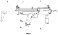
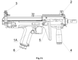
- FIG 1A , Figure 2A , Figure 3A show a side view of the caseless weapon 1A.
- This configuration comprising: the weapon 1A, the removable front sight 2, the removable dioptrical sight 3, the forward grip 4, the gunstock 5 and the magazine 6.
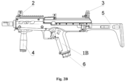
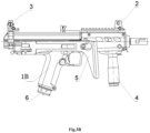
- FIG 1B , Figure 2B , Figure 3B show a side view of the weapon 1B for the semi-automatic shot.
- This configuration comprising: the weapon 1B, the removable front sight 2, the removable dioptrical sight 3, the forward grip 4, the gunstock 5 and the magazine 6.
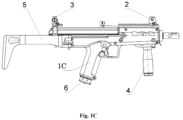
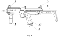
- FIG. 1C , Figure 2C , Figure 3C show a side view of the weapon 1C for automatic shot.
- This configuration comprising: the weapon 1C, the removable front sight 2, the removable dioptrical sight 3, the forward grip 4, the gunstock 5 and the magazine 6.
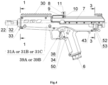
- Figure 4 show a side view of the weapon for magazine shot 1A
- Figure 6A is a longitudinal section of the weapon 1A
- Figure 7 is a fragment of a longitudinal section of the weapon 1A on the pusher of the magazine latch 35
- Figure 8 is a cross-section 1-1 on Figure 4
- Figure 9 is a cross-section 2-2 on Figure 5
- Figure 13 is a cross-section 3-3 on Figure 4 of the weapon 1A.
- Weapon 1A comprising: the magazine 6, the receiver cover 7, the cocking lever 8, the cocking lever axis 9, the lock washer of the cocking lever axis 10, the spring of the cocking lever 11, the bolt carrier 12A, the rod 13, the spring of the rod 14, the percussion piston 17, the conical bushing of the bolt 18, the shutter housing 19, the safety catch of the firing percussion 20, the spring of the firing percussion 21, the balancing gear 22, the spring washer of the balancing gear 23, the barrel 24 with smooth channel, the barrel latch 25, multifunctional cartridge 26, the conical bushing of receiver 27, the extractor 28, the lock washer of the extractor 29, the receiver 30, the trigger housing 31A, the big front nut 32, the front swivel 33, the magazine latch 34, the magazine latch pusher 35, the safety latch spring 36, the safety latch 37, the safety catch 38, the trigger bar for semi-automatic shot 39A, the sear 40, the trigger bar spring 41, the bracket of the percussion mechanism 46, the axis of the cocking piece 47, the spiral mainspring 48,
- Figure 4 show a side view of the weapon for semi-automatic shot 1B
- Figure 6B is longitudinal section of the weapon 1B in semi-automatic embodiment
- Figure 7 is fragment of a longitudinal section of the weapon 1B on the pusher of the magazine latch 35
- Figure 8 is cross-section 1-1 on Figure 4
- Figure 9 is cross-section 2-2 on Figure 5
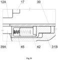
- Figure 10 is fragment of longitudinal section of the weapon 1B on the single-shot sear 42
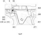
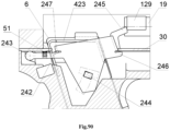
- Figure 12 is fragment of longitudinal section of the weapon 1B on the slide stop 50
- Figure 13 is cross-section 3-3 on Figure 4 of the weapon 1B.
- Weapon 1B comprising: the magazine 6, the receiver cover 7, the cocking lever 8, the cocking lever axis 9, the lock washer of the cocking lever axis 10, the spring of cocking lever 11, the bolt carrier 12A, the guide rod of the returnable spring 15, the returnable spring 16, the percussion piston17, the conical bushing of the bolt 18, the shutter housing 19, the safety catch of the firing percussion 20, the spring of the firing percussion 21, the balancing gear 22, the spring washer of the balancing gear 23, the barrel 24 with smooth channel, the barrel latch 25, the multifunctional cartridge 26, the conical bushing of receiver 27, the extractor 28, the lock washer of the extractor 29, the receiver 30, the trigger housing 31B, the big front nut 32, the front swivel 33, the magazine latch 34, the magazine latch pusher 35, the safety latch spring 36, the safety latch 37, the safety catch 38, the trigger bar for semi-automatic shot 39A, the sear 40, the trigger bar spring 41, the single-shot sear 42, the trigger bar spring 45, bracket of the percussion mechanism 46
- Figure 4 Figure 5 show side view of the weapon for automatic shot 1C
- Figure 6C is longitudinal section of the weapon 1C
- Figure 7 is fragment of a longitudinal section of the weapon 1C on the pusher of the magazine latch 35
- Figure 8 is cross-section 1-1 on Figure 4
- Figure 9 is cross-section 2-2 on Figure 5
- Figure 11 is fragment of longitudinal section of the weapon 1C on the multifunction switch 43
- Figure 12 is fragment of longitudinal section of the weapon 1C on the slide stop 50
- Figure 13 is cross-section 3-3 on Figure 4 of the weapon 1C.
- Weapon 1C comprising: the magazine 6, the receiver cover 7, the cocking lever 8, the cocking lever axis 9, the lock washer of the cocking lever axis 10, the spring of the cocking lever 11, the bolt carrier 12B, the guide rod of a returnable spring 15, the returnable spring 16, the percussion piston 17, the conical bushing of the bolt 18, the shutter housing 19, the safety catch of the firing percussion 20, the spring of the firing percussion 21, the balancing gear 22, the spring washer of balancing gear 23, the barrel 24 with smooth channel, the barrel latch 25, the multifunctional cartridge 26, the conical bushing of receiver 27, the extractor 28, the lock washer of the extractor 29, the receiver 30, the trigger housing 31C, the big front nut 32, the front swivel 33, the magazine latch 34, the magazine latch pusher 35, the safety latch spring 36, the safety latch 37, the safety catch 38, the trigger bar for the semi-automatic shot 39B, sear 40, the trigger bar spring 41, the multifunction switch 43, the multifunction switch axis 44, the trigger bar spring 45,
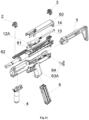
- Figure 14 is a disassembly of the magazine weapon 1A on units (side view). Units compising: the removable front sight 2, the removable dioptrical sight 3, the forward grip 4, the gunstock 5, the magazine 6, the cover of the receiver with mechanisms 60, the bolt carrier 12A with the bolt 61, the rod 13, the spring of the rod 14, the receiver with barrel and mechanisms 62, the trigger housing with mechanisms 63A, the multifunction latch 64.
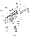
- Figure 15 is a disassembly of the semi-automatic weapon 1B on units (side view). Units comprising: the removable front sight 2, the removable dioptrical sight 3, the forward grip 4, the gunstock 5, the magazine 6, the cover of the receiver with mechanisms 60, the bolt carrier 12A with the bolt 61, the guide rod of a returnable spring 15, the returnable spring 16, the receiver with barrel and mechanisms 62, the trigger housing with mechanisms 63B, the multifunction latch 64.
- Figure 16 is a disassembly of the automatic weapon 1C on units (side view). Units comprising: the removable front sight 2, the removable dioptrical sight 3, the forward grip 4, the gunstock 5, the magazine 6, the cover of the receiver with mechanisms 60, the bolt carrier 12B with the bolt 61, the guide rod of a returnable spring 15, the returnable spring 16, the receiver with barrel and mechanisms 62, the trigger housing with mechanisms 63C, the multifunction latch 64.
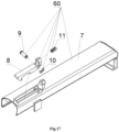
- Figure 17 is a detailing of the cover of the receiver with mechanisms 60 (side view).
- the cover of the receiver with mechanisms 60 comprising: the receiver cover 7, the cocking lever 8, the cocking lever axis 9, the lock washer of the cocking lever axis 10, the spring of cocking lever 11.
- FIG 18 is a side view of the receiver cover 7.
- the receiver cover 7 has a box-section body 65, which contains a rear plate 66.
- the bushing 67 is disposed in the middle of the internal side of rear plate 66.
- the bracket 68 for the cocking lever 8 is disposed on the external side in the front part of body 65.
- the bracket 68 has the through hole 69 for the axis of the cocking lever 9.
- the button 70 is disposed in the rear part of the bracket 68.
- the button 70 configured in the form of the washer with the blind hole 71 for the cocking lever spring 11.
- the front stop 72 disposed within the top of the body 65. Inside of the body 65 ledge with an interior chamfer 73 disposed outside. Figure 18 showing all elements of the receiver cover 7, their forms and interactions between them.
- FIG 19 is a side view of the cocking lever 8.
- the cocking lever 8 contains the lever 74, which has the hook 75 in the rear part, wherein the hook has rounded end 76.
- the through hole 77 for the axis of the cocking lever 9 disposed in the front lower part.
- the ledge in form of a button 78 with a blind hole 79 and a cylindrical ledge 80 for the cocking lever spring 11 disposed in the front part of lever 74. Wherein outer coil of the cocking lever spring 11 is pressed on the cylindrical ledge 80 and because of it, outer coil of the cocking lever spring 11 is not flying away during disassembly the cocking lever 8.
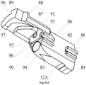
- Figure 20A is a front view of the bolt carrier 12A
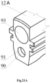
- Figure 21A is a fragment of the rear part of the bolt carrier 12A
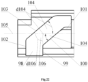
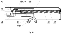
- Figure 22 is a bottom view on the cam slot 96 of the bolt carrier 12A or 12B.
- the bolt carrier 12A comprises the bar 82, the lower part of which has the form of the trapezoidal section 83.
- Enlargement 84 disposed in the rear part of the trapezoidal section 83.
- the guided ledges 86 disposed on the side surface of the bar 82, wherein said guided ledges 86 are configured to interact with the channel guide 178 of the receiver 30.
- the front upper part of the bar 82 shaped in the form of console 87.
- the ledge 88 disposed at the top in front of said console 87 and configured to interact with an inclined ledge 81 of the cocking lever 8.
- the slot 89 disposed on the edge in the front part of said console 87.
- the blind hole 90 disposed inside of the lower part of the bar 82 and configured to reciprocate the shutter housing 19.
- the through hole 91 disposed on the bottom of the blind hole 90 and configured to reciprocate the percussion piston 17.
- the through hole 92 for the guide rod of the returnable spring 15 and the blind hole 93 for the returnable spring 16 are disposed within the upper part of the bar 82.
- the inlet chamfer 94 disposed in front of the trapezoidal section 83 and configured to interact with the caseless ammunition 59.
- the support platform 95 disposed at the beginning of the console 87 near with the through hole 92.
- the support platform 96 disposed in the front part of the console 87 and the cam slot 97 for the leading ledge 132 of the shutter housing 19 is disposed on the lower surface of console 87.
- the cam slot 97 configured in form of the screwed groove, which has the inlet slot 98, the leading edge 99, edge 100 for rotation of the shutter housing 19, the free running internal edge 101, the support platform 102 and external leading edge 103.
- the edge 100 and external leading edge 103 form an acute angle 104 to the axis of the bolt 105.
- a measure of an acute angle d104 correlates to 30-45 degrees, which is optimal for the correct opening and closing of the shutter housing 19.
- the leading edge 99 and the axis of bolt 105 form a straight angle 106. Measure d106 correlates to 90 degrees.
- Figure 20A , Figure 21A , Figure 22 showing all elements of the bolt carrier 12A, their forms and interactions.
- Figure 20B is a front view of the bolt carrier 12B
- Figure 21B is a fragment of the rear part of the bolt carrier 12B
- Figure 22 is a bottom view on the cam slot 96 of the bolt carrier 12A or 12B.
- the bolt carrier 12A comprises the bar 82, the lower part of which has the form of a trapezoidal section 83.
- the enlargement 84 and the hook-shaped ledge 85 which interacts with the multifunction switch 43 in the "automatic fire" mode are disposed in the rear part of a trapezoidal section 83.
- the guided ledges 86 disposed on the side surface of the bar 82 and configured to interact with the channel guide 178 of the receiver 30.
- the front upper part of the bar 82 shaped in the form of console 87.
- the ledge 88 disposed at the top in front of said console 87 and configured to interact with the inclined ledge 81 of the cocking lever 8.
- the slot 89 disposed on the edge in the front part of said console 87.
- the blind hole 90 disposed inside of the lower part of the bar 82 and configured to reciprocate the shutter housing 19.
- the through hole 91 disposed on the bottom of the blind hole 90 and configured to reciprocate the percussion piston 17.
- the through hole 92 for guide rod of the returnable spring 15 and blind hole 93 for returnable spring 16 are disposed within upper part of the bar 82.
- the inlet chamfer 94 disposed in front of the trapezoidal section 83 and configured to interact with the caseless ammunition 59.
- the support platform 95 disposed at the beginning of the console 87 near with the through hole 92.
- the support platform 96 disposed in the front part of console 87 and the cam slot 97 for the leading ledge 132 of the shutter housing 19 is disposed on the lower surface of the console 87.
- the cam slot 97 configured in form of the screwed groove, which has the inlet slot 98, the leading edge 99, the edge 100 for rotation of the shutter housing 19, the free running internal edge 101, the support platform 102 and the external leading edge 103.
- the edge 100 and the external leading edge 103 form an acute angle 104 to the axis of the bolt 105.
- a measure of an acute angle d104 correlates to 30-45 degrees, which is optimal for the correct opening and closing of the shutter housing 19.
- the leading edge 99 and the axis of bolt 105 form a straight angle 106. Measure d106 correlates to 90 degrees.
- Figure 20B , Figure 21B , Figure 22 showing all elements of the bolt carrier 12B, their forms and interactions.
- Figure 23 is a side view of the rod 13.
- the rod 13 has the washer with the radial chamfer 107, which passes into the cylindrical part 108, which passes into the washer with the radial chamfer 107.
- Said rod is element of the weapon 1A.
- Figure 23 showing all elements of the rod 13, their forms and interactions.
- Figure 24 is a side view of the guide rod 15.
- the guide rod 15 configured in the form of the spherical head 109, which passes into the cylindrical part 110, which via the conical transition 111 passes into the cylindrical part 112 with bigger diameter, which passes into the washer with the radial chamfer 107.
- Said guide rod is an element of the weapon 1B and 1C. Figure 24 showing all elements of the guide rod 15, their forms and interactions.
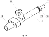
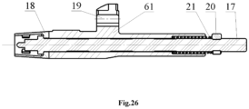
- Figure 25 is a side view of the bolt 61 and Figure 26 is a longitudinal section of the bolt 61.
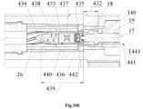
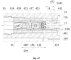
- the bolt 61 comprising: the percussion piston 17, the conical bushing of the bolt 18, shutter housing 19, the safety catch of the firing percussion 20, the spring of the firing percussion 21.
- Figure 27 is a detailing of the bolt 61 (side view). This configuration comprising: the percussion piston 17, the conical bushing of the bolt 18, shutter housing 19, the safety catch of the firing percussion 20, the spring of the firing percussion 21.
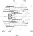
- Figure 28 is a longitudinal section of the conical bushing of the bolt 18.
- the conical bushing of the bolt 18 configured to rotate on the percussion piston 17 and pressed by the spring of the firing percussion 21 to the glazed area 140 at the end of the cylindrical head 127 of the shutter housing 19.
- Figure 28 shows that the conical bushing on the bolt 18 configured as the truncated cone 113 with the blind conical hole 114, which comes into the through hole 115, which is formed the stout wall 116 at the outlet of the big base of the truncated cone 113.
- Not less than three ledges 117 are configured at the inlet in the blind conical hole 114. Said ledges 117 fixed the caseless ammunition 59 and protecting it from the inertial accumulation by the percussion piston 17 in case the weapon dropping.
- Figure 28 showing all elements of the conical bushing of the bolt 18, their forms and interactions.
- Figure 29 is a side view of the percussion piston 17.
- the percussion piston 17 configured in stepped shaft form.
- the conical section 118 which passes into the cylindrical section with smaller diameter 119 disposed forepart, wherein the inclined ledge 120 disposed at the joint of the conical section 118 and the cylindrical section with smaller diameter 119.
- An angle of the ledge incline d120 to axis of the firing percussion 121 correlates to 30-45 degrees, which is optimal value to ensure peeling force of the ammunition 59 with the threaded bushing 166 of the multifunctional cartridge 26.
- the cylindrical section with smaller diameter 119 passes into the cylindrical section with bigger diameter 122, which passes into the cylindrical piston 123.
- the cylindrical piston 123 passes into the rod section with the grooves 124, wherein the rear groove configured for the safety catch of the firing percussion 20.
- Figure 29 showing all elements of the firing percussion 17, their forms and interactions.
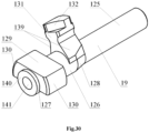
- FIG 30 is a side view of the shutter housing 19
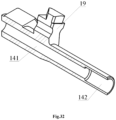
- Figure 31 is a fragment of the shutter housing 19
- Figure 32 is a longitudinal section of the shutter housing 19
- Figure 33 is a longitudinal section of the leading ledge 132 of the shutter housing 19.
- the shutter housing 19 has the cylindrical section 125, which passes into the thickened cylindrical section 126, which passes into the cylindrical head 127. Through passage from the cylindrical section 125 to the thickened cylindrical section 126, the chamfer 128 is disposed therein. In the junction point between the thickened cylindrical section 126 and the cylindrical head 127 the locking lug 129 is disposed therein in the form of not less than two ledges, ends of which configured as the radius surfaces 130.
- the stepped ledge is disposed therein, which comprising the base 131 and the leading ledge 132, configured to interact with the cam slot 97 of the bolt carrier 12A or 12B.
- the leading ledge 132 has rear leading edge 133, side edge of the free running 134 and 135, rear radius chamfers 136, the external sideway forepart scarf 137 and the external radius section 138.
- Two cylindrical grooves with inclined sides 139 disposed on the base 131.
- the base 131 is disposed at angle to the locking lug 129.
- the glazed area 140 for the conical bushing on the bolt 18 disposed at the end of the cylindrical head 127.
- the central cylindrical channel 141 for the percussion piston 17 disposed within the shutter housing 19.
- the rear part of the central cylindrical channel 141 has the blind cylindrical hole 142 with bigger diameter, which configured to interact with the firing percussion spring 21 and the safety catch of the firing percussion 20.
- Figure 30 , Figure 31 , Figure 32 , Figure 33 showing all elements of the shutter housing 19, their forms and interactions.
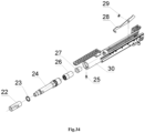
- Figure 34 is a detailing of the receiver with the barrel and mechanisms 62 (side view). This configuration comprising: the balancing gear 22, the spring washer of the balancing gear 23, the barrel 24 with smooth channel, the barrel latch 25, multifunctional cartridge 26, the conical bushing of the receiver 27, the extractor 28, the lock washer of the extractor 29, the receiver 30.
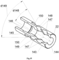
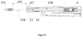
- FIG 35 is a side view of the balancing gear 22.
- the balancing gear 22 configured in the form of a cylinder 143, inside of which the smooth cylindrical section 144 is disposed, which passes into the conical section 145, which passes into the cylindrical groove with the threaded section 146.
- the inclined holes 147 with the acute angle 148 to the longitudinal axis disposed in the front part of the cylinder 143.
- the inclined holes 147 in the cross-section between them formed an angle 149.
- the slots 150 are made behind the inclined holes 147 on the outer part of the cylinder 143.
- Figure 35 showing all elements of the balancing gear 22, their forms and interactions.
- Figure 36 is a front view of the spring washer of the balancing gear 23.
- the spring washer of the balancing gear 23 configured as the split ring 151 and the three-sided flange 152 on the internal side.
- the spring washer of the balancing gear 23 with their three-sided flange 152 abuts against threaded section 155 for balancing gear 23 when the balancing gear 23 is removed from barrel 24, which allows the balancing gear 23 to not be lost.
- the ends of the split ring 151 have a bias 153.
- the measure of bias T153 correlates 0.2D23, where D23 - is the outer diameter of the spring washer of the balancing gear 23. Said measure is optimal for performing a spring clamp function.
- Figure 36 showing all elements of the spring washer of the balancing gear 23, their forms and interactions.
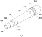
- FIG 37 is a side view of the barrel 24.
- the barrel 24 has the smooth conical section 154, which passes into the threaded section 155, which passes into the slot 156, which passes into the cylindrical section with the splineway 157 for a wrench, which passes into the cylindrical section 158 which passes into the multifaceted area 159 for a wrench, which passes into the smooth cylindrical section with the groove 160 for the barrel latch 25.
- the smooth cylindrical section with the groove 160 passes into the circular groove 161, which passes into the threaded section with the buttress thread 162, which passes into the smooth cylindrical section 163.
- the internal channel 164 is smooth without rifling.
- Said barrel sections 24 have different thickness, which are shown on Figure 36 , Figure 37 .
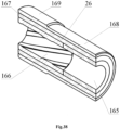
- Figure 38 is a longitudinal section of the multifunctional cartridge 26.
- the multifunctional cartridge 26 comprising the threaded bushing 165, the internal smooth bushing 166, at least one middle bushing 167 and the external bushing with variable diameter 168, which has bigger diameter 169.
- the threaded bushing 165 and the inner smooth bushing 166 are made of carbide and refractory material.
- the threaded bushing 165 made of carbide and refractory material and has two or more threaded grooves. The pitchs and forms of grooves depends on applying ammunition.
- the bushings 165, 166, 167 and 168 are inserted into each other with tension and created the multifunctional cartridge 26. Outer surface of the bushings 165, 166, 167 and 168 are highly polished.
- the multifunctional cartridge 26 provide high pressure during firing, and high polishing ensures minimal heat loss in the hottest part.
- the polished surface reflecting the heat flux as a thermos.
- the carbide and refractory threaded groove 165, the inner smooth bushing 166 provide high reliability of the weapon during the high temperature of gases produced when the propellant is burnt.
- Figure 38 showing all elements of the spring washer of the multifunctional cartridge 26, their forms and interactions.
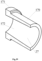
- Figure 39 is a longitudinal section of the conical bushing of the receiver 27.
- the conical bushing of the receiver 27 has the cylindrical section 170 which passes into the smaller cylindrical section 171.
- the conical hole 172 disposed inside of the conical bushing of the receiver 27 the small base of which is located at the end of the cylindrical section 170.
- Figure 39 showing all elements of the conical bushing of receiver 27, their forms and interactions.
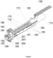
- Figure 40 is a side view of the receiver 30 and Figure 41 is a longitudinal section of the receiver 30.
- the receiver 30 comprising:
- the lower part of the receiver 181 configured in the form of a box-section figure, wherein the cam hole 183 for passage the cocking piece 49A or 49B and the magazine 6 is disposed on the bottom of lower part of the receiver 181.
- the channel guides 178 are fastened to the lower part of the receiver 181 and the barrel chamber 173 via the cap screws 184.
- the stop 185 for the trigger box 31A or 31B or 31C disposed on the rear part of lower part of the receiver 181.
- the stop 185 has the cross through hole 186, which configured to interact with the multifunction latch 64 and two vertical threaded holes 187, wherein said stop is mounted on the rear part of the receiver 181 below via screws 188.
- the rear swivel 189 is disposed on the stop 185.
- the receiver 30 also comprising the bracket 190 having the threaded holes 191 in the lower part for fastening the bracket 190 to the lower part of the receiver 181 and a longitudinal hole 193, which configured to interact with a ramrod 58.
- Figure 42 is a detailing of the receiver 30 (side view). This configuration comprising: the barrel chamber 173, the locking screw of the gun chamber 174, the feed ramp 175, the cap screw 177, the channel guide 178, the lower part of receiver 181, the cap screw 184, the stop 185, the screws 188, the bracket 190, the screws 192, the screws 195, the rear sight rail 196, the front sight rail 199, the plate 200, the screws 203.
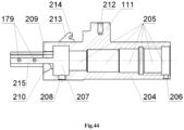
- FIG 43 is a side view of the barrel chamber 173 and Figure 44 is a longitudinal section of the barrel chamber 173.
- the barrel chamber 173 has a cylindrical part 204.
- a multistage cylindrical hole with a threaded section 205 is disposed, which configured to mounting the conical bushing of the receiver 27, to mounting the multifunctional cartridge 26 and to mounting the barrel 24.
- the cross threaded hole 206 is the inlet of the multistage cylindrical hole 205 with threaded section.
- the multistage cylindrical hole with threaded section 205 passes into the cylindrical groove 207, the lower part of which has a threaded hole 208 for the locking screw of the barrel chamber 174.
- the cylindrical groove 207 passes into a complex-shaped section 209, which follows the shape of the front part of the shutter housing 19.
- On the inlet of the complex-shaped section 209 is two leading cylindrical guiding chamfers 210 disposed therein.
- the base In the middle at the top of the cylindrical section 204 the base with a dovetail-type ledge 211 disposed therein, in which the threaded hole 212 for a screw 195 is disposed for fastening the front sight rail 199.
- the inclined ledge 213 disposed therein, for interaction with the cocking lever 8.
- the cylindrical groove 214 disposed on inclined ledge 213.
- the rear end of the cylindrical part 204 has consoles 215 in the form of channel guides, which is configured to interact with the bolt carrier 12A or 12B (depending on the choice of an embodiment of the weapon) and the shutter housing 19.
- the upper grooves 216 are disposed on the external surface of the cylindrical part 204, configured to interact with the receiver cover 7.
- Figure 43 , Figure 44 showing all elements of the spring washer of the barrel chamber 173, their forms and interactions.
- Figure 45 is a detailing of the trigger housing with mechanisms 63A for automatic weapon 1A.
- the trigger housing with mechanisms 63A comprising: the trigger housing 31A, the big front screw 32, the front swivel 33, the magazine latch 34, the safety catch 38, the trigger bar spring 41, the latch of ramrod 56, the spring of the latch of ramrod 57, the ramrod 58, the multifunction latch 64, the retainer mechanism 217, the firing mechanism for magazine shot 218, the percussion mechanism 221 for the magazine shot.
- Figure 46 is a detailing of the trigger housing with mechanisms 63B for semi-automatic weapon 1B.
- the trigger housing with mechanisms 63B comprising: the trigger housing 31B, the big front screw 32, the front swivel 33, the magazine latch 34, the safety catch 38, the trigger bar spring 41, the slide stop 50, the slide stop spring 51, the latch of ramrod 56, the spring of the latch of ramrod 57, the ramrod 58, the multifunction latch 64, the retainer mechanism 217, the firing mechanism for semi-automatic shot 219, the percussion mechanism 222 for semi-automatic shot and automatic shot.
- Figure 47 is a detailing of the trigger housing with mechanisms 63C for automatic weapon 1C.
- the trigger housing with mechanisms 63C comprising: the trigger housing 31C, the big front screw 32, the front swivel 33, the magazine the latch 34, the safety catch 38, the trigger bar spring 41, the slide stop 50, the slide stop spring 51, the latch of ramrod 56, the spring of the latch of ramrod 57, the ramrod 58, the multifunction latch 64, the retainer mechanism 217, the firing mechanism for automatic shot 220, the percussion mechanism 222 for semi-automatic and automatic shot.
- Figure 48 is a side view of the big front nut 32.
- the big front nut 32 is configured in the form of a truncated cone 223, which passes into the cylindrical section with the external thread 224.
- the through hole 225 disposed in said nut.
- Figure 48 showing all elements of the big front nut 32, their forms and interactions.
- Figure 49 is a side view of the front swivel 33.
- the front swivel 33 is configured in the form of a ring 226, on the side of which the ledge 226A and the sling swivel 227 are disposed in the form of an oval ring.
- Figure 49 showing all elements of the front swivel 33, their forms and interactions.
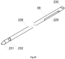
- Figure 50 is a side view of the ramrod 58.
- the ramrod 58 configured in the form of a rod 228, at the front end of which a slotted slot 229 is disposed, which passes into the flat end 230 in the form of a srewdriver.
- the rear end of the rod 228 is configured in the form of a conical head 231, in front of which a groove 232 for retention of the latch of ramrod 56 is disposed.
- Figure 50 showing all elements of the ramrod 58, their forms and interactions.
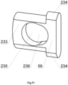
- Figure 51 is a side view of the latch of ramrod 56.
- the latch of ramrod 56 is configured in the form of a plate 233 with rounded ledges 234 on the lower part.
- the through semicircular hole 235 is disposed in the center of the plate 233.
- the semicircular slot 236 is disposed in the lower part of the through hole 235.
- Figure 51 showing all elements of the latch of ramrod 56, their forms and interactions.
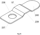
- Figure 52 is a side view of the spring of the latch of ramrod 57.
- the spring of the latch of ramrod 57 is configured in the form of the flat spring 237, which has through hole 238 at the front end.
- the bulge 239 is disposed in the middle of the flat spring.
- the rear part 240 of the flat spring is rounded. Figure 52 showing all elements of the spring of the latch of ramrod 57, their forms and interactions.
- Figure 53 is a side view of the slide stop 50.
- the slide stop 50 configured in the form of a plate 241, in front upper part of which ledge 242 with a hinge 243 in the form of the washer is disposed therein.
- the "T" shaped ledge 244 is disposed on the external side of plate 241.
- Two ledges are disposed at the end of said plate 241, upper ledge 245 for retention the locking lug 129 of the bolt body 19 and lower ledge 246 for stop it into the receiver 30, because of this, the upper ledge 245 in upper position installed on the trajectory of the locking lug 129 of the bolt body 19.
- the ledge for ledge 424 of magazine 6 platform 423 is disposed 247 on the internal side of plate 241.
- the hook 248 disposed on the internal side of the lever 242 for the spring of the slide stop 51.
- Figure 53 showing all elements of the slide stop 50, their forms and interactions.
- Figure 54 is a longitudinal section of the multifunction latch 64.
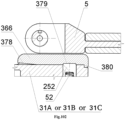
- the multifunction latch 64 comprising: the multifunction latch lever 52, the multifunctional latch stop 53 the lock pin splint 54, the spring of the lock pin splint 55.
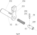
- FIG. 55 is a detailing of the multifunction latch 64 (side view).
- the multifunction latch 64 comprising: multifunction latch lever 52, the multifunction latch lever 52 is configured in the form of the rod 252, in front of which the lever 253 disposed therein with inclined area 254, multifunctional latch stop 53 within which a through cross hole 249 is disposed for the lock pin 54, which has spherical ends 250 and the groove in the middle 251, the spring of the lock pin splint 55.
- Figure 56 is a longitudinal section of the multifunction latch lever 52.
- the multifunction latch lever 52 comprises the rod 252 with the lever 253 in front part.
- the protrusions, rear 256 and front 257 are disposed on the enlargement 255, which is disposed at the end of the lever 253.
- the rear protrusion 256 is configured for retention the multifunction latch lever 52 in the trigger housing 31A, or 31B, or 31C.
- the front protrusion 257 functions as a button for the multifunction latch lever 52.
- the blind hole 258 is disposed in the rod 252 from the side of the lever 253 against the lock pin spring 55 and the multifunction latch stop 53.
- the through slot 259 for lock pin splint 54 is disposed in the rod 252.
- the multifunction latch stop 53 and the lock pin 54 are configured to reciprocate in the multifunction latch lever 52.
- Figure 56 showing all elements of the multifunction latch lever 52, their forms and interactions.
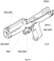
- Figure 57A is a side view of the trigger housing 31A.
- the trigger housing 31A comprising: the right half of the trigger housing 260A and left half of the trigger housing 261A, lower ventilation bushings 262, which additionally function as the hinge for installation a trunnion for a tripod, that provid a precision shoot from a fixed position, cap screws 263, threaded bushings 264 for cap screws 263, threaded bushing with the splineway 265 for cap screw 263 in the gunstock 5 installation place.
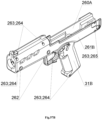
- Figure 57B is a side view of the trigger housing 31B.
- the trigger housing 31B comprising: the right half of the trigger housing 260A and left half of the trigger housing 261B, lower ventilation bushings 262, which additionally function as the hinge for installation a trunnion for a tripod, that provid a precision shoot from a fixed position, cap screws 263, threaded bushings 264 for cap screws 263, threaded bushing with the splineway 265 for cap screw 263 in the gunstock 5 installation place.
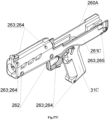
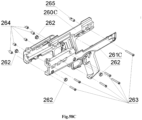
- Figure 57C is a side view of the trigger housing 31C.
- the trigger housing 31C comprising: the right half of the trigger housing 260C and left half of the trigger housing 261B, lower ventilation bushings 262, which additionally function as the hinge for installation a trunnion for a tripod, that provid a precision shoot from a fixed position, cap screws 263, threaded bushings 264 for cap screws 263, threaded bushing with a splineway 265 for cap screw 263 in gunstock 5 installation place.
- Figure 58A is a detailing of the trigger housing 31A (side view). This configuration comprising: the right half of the trigger housing 260A and left half of the trigger housing 261A, lower ventilation bushings 262, cap screws 263, threaded bushings 264, threaded bushing with the splineway 265.
- Figure 58B is a detailing of the trigger housing 31B (side view). This configuration comprising: the right half of the trigger housing 260A and left half of the trigger housing 261B, lower ventilation bushings 262, cap screws 263, threaded bushings 264, threaded bushing with the splineway 265.
- Figure 58C is a detailing of the trigger housing 31C side view). This configuration comprising: the right half of the trigger housing 260C and left half of the trigger housing 261B, lower ventilation bushings 262, cap screws 263, threaded bushings 264, threaded bushing with the splineway 265.
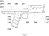
- Figure 59 is a side view of the outside of the left half of the trigger housing 261A or 261B
- Figure 60 is a side view of the inside of the left half of the trigger housing 261A or 261B.
- the threaded hole 266 for the big front nut 32 and the handguard 267 are disposed in the front part of the left half of the trigger housing 261A or 261B.
- the left half of the trigger housing 261A or 261B having the pistol grip 268 below in the middle.
- the rectangular hole 269 for the safety catch 38 and hole 270 for the magazine latch 34 are disposed in the pistol grip 268.
- the "T" shaped hole 271 for the slide stop 50 (only for the left half of the trigger housing 261B) is disposed on the pistol grip 268 .
- Slots 273, 274, which biasing with the inclined area 275 and complex-shaped hole 276 for the multifunction latch 64 are disposed in the rear part of the left half of the trigger housing 261A or 261B.
- Ventilative holes 277 and hook 278 for retention the front sight Picatinny-type rail 199 are disposed on the upper front part of the left half of the trigger housing 261A or 261B.
- the trigger guard 279 is disposed above the pistol grip 268 for the safety catch 38 protection, for the case of the weapon dropping.
- the pistol grip 268 and handguard 267 are fastened via the trigger guard 280, on which protrusions are mounted for magazine latch 34 for protection from accidental press.
- the protrusion 282 is disposed in the upper part of the handguard 267 behind the ventilative holes 277 to provide the hermetization of the receiver cover 7 in off position.
- Cross holes 283 for the cap screws 263 are disposed on the left half of the trigger housing 261A or 261B.
- the holes 284 for the lower ventilation grooves 262 are disposed in the side walls of the handguard 267.
- the left half of the trigger housing 261A or 261B having within the channel 285, cavity 286 and slot 287 for mounting the receiver with the barrel and mechanisms 62.
- the cavity 288 is configured for the magazine latch 34.
- the cavity 289 is configured for hauling with the hook 39A or 39B and the cavity 290 for the trigger bar spring 41.
- the cavity 291 for the cocking piece 49A or 49B is disposed at the beginning of the cavity 290.
- the cavity 292 configured for the stop 185.
- the rectangular hole 293, inlet conical hole 294, and slots for collecting dirt 295 are configured for the magazine 6.
- the hole 296 is configured for the cocking indicator, trigger 49A or 49B.
- the lower rectangular holes 297 and cylindrical hole 298 are configured for mounting the forward grip 4.
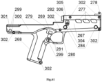
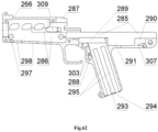
- Figure 61 is an exterior side view of the right half of the trigger housing 260A or 260C and Figure 62 is an interior side view inside of the right half of the trigger housing 260A or 260C.
- the right half of the trigger housing 260A or 260C having threaded hole 266 for the big front nut 32 and handguard 267 in the front part.
- the left half of the trigger housing 261A or 261B having the pistol grip 268 below in the middle.
- the pistol grip 268 having the rectangular hole 269 for safety catch 38 and the complex-shaped hole 299 for the magazine latch 34.
- the hole 301 for the multifunction latch 64 is disposed in the rear part 300 of the right half of the trigger housing 260A or 260C.
- the trigger guard 279 is disposed above the pistol grip 268 for the safety catch 38 protection, for the case of the weapon dropping.
- the pistol grip 268 and handguard 267 are fastened via the trigger guard 280, on which the protrusions are mounted for the magazine latch 34 for protection from accidental press.
- the protrusion 282 is disposed in the upper part of the handguard 267 behind the ventilative holes 277 to provide the hermetization of the receiver cover 7 in off position.
- Cross threaded holes 302 for the threaded bushings 264 and threaded bushing with the splineway 265 are disposed on the right half of the trigger housing 260A or 260C.
- the holes 284 for the lower ventilation grooves 262 disposed in the side walls of the handguard 267.
- the channel 285, cavity 286 and slot 287 for installation the receiver with the barrel and mechanisms 62 are disposed within the right half of the trigger housing 260A or 260C.
- the assembly holes 303 for the safety latch 37, safety spring retaining pin 36, magazine latch pusher 35 are disposed upper the pistol grip 268.
- the cavity 288 is configured for the magazine latch 34 as well.
- the cavity 289 is configured for hauling with the hook 39A or 39B and the cavity 290 is configured for the trigger bar spring 41.
- the cavity 291 for the cocking piece 49A or 49B is disposed at the beginning of the cavity 290.
- the rectangular hole 293, inlet conical hole 294, and slots for collecting dirt 295 are configured for the magazine 6.
- the protrusion 304 with the cross hole 305 for the latch of the ramrod 56 and the longitudinal hole 306 for the ramrod 58 are disposed outside on the handguard 267 near the trigger guard 280.
- the through groove 307 is configured for the multifunction latch 43 (only for the right half of the trigger housing 260C).
- the lower rectangular holes 297 and the cylindrical hole 298 are configured for fastening the front handle 4.
- the "T" shaped slot 308 for mounting the gunstock 5 is disposed in the rear part 300 of the right half of the trigger housing 260A or 260C.
- the slot 309 for the spring of the ramrod latch 57 is disposed at the beginning of the cavity 286.
- Figure 61 , Figure 62 showing all elements of the right half of the trigger housing 260A or 260C, their forms and interactions.
- FIG 63 is a side view of the adjustable front sight 2.
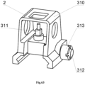
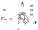
- the adjustable front sight 2 comprises the front sight bracket 310 into which the front sight 311 is screwed in, wherein the front sight bracket 310 is mounted on the front sight Picatinny-type rail 199 via the cap screw 312 and cylindrical nut 313.
- Figure 64 is a detailing of the adjustable front sight 2 (side view). This configuration comprising: the front sight bracket 310, front sight 311, cap screw 312 and cylindrical nut 313 with the splineway for a screwdriver.
- Figure 65 is a side view of the adjustable dioptrical sight 3.
- the adjustable dioptrical sight 3 comprising: the bracket 314 within the adjustment screw 315 and the impeller with diopter holes 316 is put on the bracket 314 and said impeller has the possibility to rotate on the adjustment screw 315 and constantly compressed by the conical spring 317.
- the retainer screw 318 is mounted in the bracket 314 is fixing the adjustment screw 315 against rotation, wherein the bracket 314 is mounted on the rear sight Picatinny-type rail 196 via the adjustment screw 312 and cylindrical nut 313.
- Figure 66 is a detailing of the adjustable dioptrical sight 3 (side view). This configuration comprising: the bracket 314, adjustment screw 315, impeller with the diopter holes 316, conical spring 317, adjustment screw 312, cylindrical nut 313, retainer screw 318 with the splineway for a screwdriver.
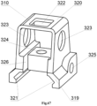
- Figure 67 is a side view of the front sight bracket 310.
- the front sight bracket 310 contains the plate 319, which passes into the clamp 320.
- Clamp 320 is configured in the form of the curved plate of trapezoidal shape.
- the plate 319 having the complex-shaped through slot 321 which follows the shape of the sight Picatinny-type rail.
- the hole 322 disposed on top in the middle of the clamp 320 and configured for the thickness of the clamp wall 320.
- the light holes 323 are disposed on the side walls of the clamp 320 at the junction with the plate 319.
- the threaded hole 324 for the front sight 311 is disposed on top in the middle of the plate 319.
- the cross hole 325 for the adjustment screw 312 is disposed at the back on the side surface of the plate 319.
- Through longitudinal slot 326 is disposed behind the threaded hole 324 in front of the wall of the clamp 320 for the entire thickness of the wall plate 319. Because of the through longitudinal slot 326, the front sight bracket 310 works as a spring clip that ensures reliable retention of the front sight bracket 310 to the rear sight rail 196.
- Figure 67 showing all elements of the front sight bracket 310, their forms and interactions.
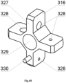
- Figure 68 is side view of the impeller with the diopter holes 316.
- the impeller with the diopter holes 316 having the blades 327 with the diopter holes 328 with the through axial hole 329.
- the retainer pin 330 is disposed on one of the impeller blades 327.
- Figure 68 showing all elements of the impeller with the diopter holes 316, their forms and interactions.
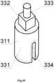
- Figure 69 is a side view of the front sight 311.
- the front sight 311 having the cylindrical section with the thread 331, which passes into a prismatic section 332, which passes into the cylindrical section 333.
- the through slot 334 is disposed in the cylindrical section with the thread 331.
- Figure 69 showing all elements of the front sight 311, their forms and interactions.
- Figure 70 is a side view of the adjustment screw 315.
- the adjustment screw 315 having the cylindrical section with the thread 335, which passes into the cylindrical section 336 along the perimeter of which the slots 337 are disposed, which configured for retention of the adjustment screw 315 via retainer screw 318 in the bracket 314 of the dioptrical sight 3.
- the cylindrical section 336 passes into the washer 338.
- Through slot 339 is slotted in the washer 338 and in the cylindrical section 336.
- the cylindrical section 336 and washer 338 on section with the slot 339 are spring-loaded, which provids retention of the adjustment screw 315 in the set position.
- Figure 70 showing all elements of the adjustment screw 315, their forms and interactions.
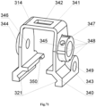
- Figure 71 is a side view of the bracket 314.
- the bracket 314 is configured in the form of the plate 340, which passes into the clamp 341.
- the clamp 341 is configured in a form of a curved plate of trapezoidal shape.
- the complex-shaped through slot 321 is disposed in plate 340 and follows the form of the sight Picatinny-type rail.
- the hole 342 disposed in the center of the top of the clamp 341 for the thickness of the clamp wall.
- the clamp 341 having the cylindrical protrusions 343 and 344 on the side walls of the clamp, wherein the cylindrical protrusion 343 having the smooth hole 345, and the other protrusion 344 having the threaded hole 346.
- the holes 345 and 346 configured for the adjustment screw 315.
- Threaded hole 347 for the retainer screw 318 is disposed in the cylindrical protrusion 343 on the side surface of the protrusion for the thickness of the wall.
- Cross hole 349 for the adjustment screw 312 disposed in front on the side surface of the plate 340.
- the through longitudinal slot 350 is disposed in front of the wall of the clamp 341 on the entire wall thickness of the plate 340. Because of the through longitudinal slot 350 the front sight bracket 314 works as a spring clip that ensures reliable retention of the front sight bracket 314 to the front sight rail 199.
- Figure 71 showing all elements of the bracket 314, their forms and interactions.
- Figure 72 is a side view of the forward grip 4.
- the forward grip 4 comprising: the body 351 with mounted threaded cover 352 and the retainer spring-loaded by the spring of the locking pin 356 and configured in the form of the locking pin 353, which is mounted in the body 351, the locking pin head 354 is fixed via splint pin of the locking pin 355 is mounted at the end of the locking pin 353 that comes out of the body 351 .
- Figure 73 is a detailing of the forward grip 4 (side view). This configuration comprising: the body 351, threaded cover 352, locking pin 353, locking pin head 354, splint pin of locking pin 355, spring of the locking pin 356.
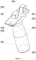
- Figure 74 is a side view of the body 351.
- the body 351 having the plate 357.
- the holes 358, 359 for locking pin 353 and for spring of the locking pin 356 are disposed in front of the plate 357.
- the rear end of the plate 357 connected to the conical cylindrical part 360, inside of which the cavity 361 with thread 362 at the output for the threaded cover 352 is disposed thereon.
- Two "L" shaped protrusions 363, 364 with the slot 365 disposed on the upper surface in the middle of the plate 357.
- the body used as a wrench for the balancing gear 22 and barrel 24.
- Figure 75 showing all elements of the forward grip body 351 their forms and interactions.
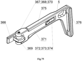
- FIG 75 is a side view of the gunstock 5.
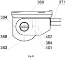
- the gunstock 5 comprising: the bracket of the gunstock 366 having the bushing of the gunstock axis 367, in which the gunstock of the axis 368 spring-loaded with the spring of the gunstock axis 370 and fixed via pin of the gunstock axis 369 in the gunstock base 371 is mounted, the adjustment lever 372 is configured to swing on the axis of the adjustment lever 373 and interact with the gunstock body 375, the smooth recoil pad 376.
- Figure 76 is a detailing of the gunstock 5 (side view). This configuration comprising: the bracket of the gunstock 366, the bushing of the gunstock axis 367, the gunstock of the axis 368, the pin of the gunstock axis 369, the spring of the gunstock axis 370, the gunstock base 371, the adjustment lever 372, the axis of the adjustment lever 373, the spring of the adjustment lever 374, the gunstock body 375, the smooth recoil pad 376.
- the gunstock body 375 is put on the base of the gunstock 371 and configured to reciprocate along the base of the gunstock 371 and the smooth recoil pad 376 disposed in the gunstock body 375.
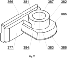
- Figure 77 is a front view of the bracket of the gunstock 366 and Figure 78 is a rear view of the bracket of the gunstock 366.
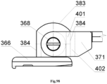
- the gunstock bracket 366 is configured in the form of "T" shaped section 377 with inclined slot 378, blind hole 379 for the multifunction latch 64 and with the locking protrusion 380.
- the complex-shaped protrusion 381 is disposed in the upper part on the other side of the "T" shaped section 377 in the form of the cylinder 382 and in the lower part in the form of the protrusion 383 with inclined sides 384, horizontal platform 385 and radius side 386.
- the through hole 387 for the gunstock of the axis 368 is disposed in the protrusion 381.
- Figure 77 , Figure 78 showing all elements of the bracket of the gunstock 366, their forms and interactions.
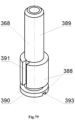
- Figure 79 is a front view of the gunstock axis 368 and Figure 80 is a rear view of the gunstock axis 368.
- the gunstock axis 368 is configured in the form of the rod 388, which passes into the rod with the smaller diameter 389.
- the circular groove 390 is disposed in the rod 388.
- Two slots located at 180 degrees along the rod 388, the longitudinal slot 391 and the blind slot 392 are disposed after the circular groove 390. These slots are configured for the pin of the gunstock axis 369.
- the splineway 393 for a screwdriver is disposed at the beginning of the rod 388.
- Figure 79 , Figure 80 showing all elements of the gunstock axis 368, their forms and interactions.
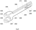
- Figure 81 is a side view of the gunstock base 371.
- the gunstock base 371 is configured in the form of the complex-shaped bracket 394 with the "T” shaped protrusion 395.
- the "T" shaped protrusion 395 having slots 396 for collecting dirt configured to provide reliable operation of the gunstock body 375.
- Behind the "T" shaped protrusion 395 the rectangular slot is disposed therein 397 with the through hole 398 for passage of the protrusion 410, adjustment lever 372 and the blind hole 399 for the spring of the adjustment lever 374.
- the cross through hole 400 for mounting the axis of the adjustment lever 373 is disposed in the middle of the rectangular slot 397.
- Figure 82 is a side view of the adjustment lever 372.
- the gunstock adjustment lever 372 is configured in the form of the lever 408 with blind hole 409 on one side for the spring of adjustment lever 374.
- the protrusion 410 with the inclined surface 411 disposed on the other side of the lever 408.
- Through hole 412 for the axis of the adjustment lever 373 is disposed in the middle of the lever 408.
- Figure 82 showing all elements of the adjustment lever 372, their forms and interactions.
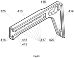
- Figure 83 is a side view of the gunstock body 375.
- the body of the gunstock 375 is configured in the form of the plate 413 with protrusion 414 in the form of a plate, which corresponds with the form of the smooth recoil pad 376.
- the guide "T" shaped blind slot 416 disposed in front of said plate 413 and configured to connect the gunstock body 375 with the gunstock base 371.
- Cross grooves 417 for the adjustment lever 372 are disposed in the guide "T” shaped blind slot 416.
- the first cross groove 417 configured with the chamfer 418 having negative incline 419.
- the rectangular hole 420 disposed in the protrusion 414 for the smooth recoil pad 376.
- Figure 83 showing all elements of the gunstock body 375, their forms and interactions.
- Figure 84 is a fragment of a cross section of the latch of the ramrod 56
- Figure 85 is a fragment of a longitudinal section of the latch of the ramrod 56.
- Said figures are showing operation of the latch of the ramrod 56 in the off position.
- the flat spring 237 of the ramrod latch 56 is in the loaded position due to the bulge 239, which is pressed to the receiver with the barrel and mechanisms 62, and the rear part 240 of the flat spring 237 is clamped in the cavity 309 of the trigger housing 31A or 31B or 31C.
- the front end of the flat spring 237 pushes the ramrod latch 56 while the semicircular slot 236 of the ramrod 56 enters the groove 232 of the ramrod 58 and latches it in a place.
- Figure 86 is a fragment of a cross section of the latch of the ramrod 56 and Figure 87 is a fragment of a longitudinal section of the latch of the ramrod 56. Said figures are showing operation of the latch of the ramrod 56 in the on position. If the ramrod 58 is to be removed, press the latch of the ramrod 56. The front end of the flat spring 237 presses against the receiver with the barrel and mechanisms 62, and the semicircular slot 236 comes out of the groove 232 of the ramrod 58, while the groove 232 will be located opposite the through semicircular hole 235, which allows to remove the ramrod 58.
- the conical head 231 of the ramrod 58 allows to insert the ramrod 58 into the latch of the ramrod 56 by direct pressing of the conical head 231 on the through semi-circular hole 235, which speeds up the whole process.
- the latch of the ramrod 56 is held in the trigger housing 31A or 31B or 31C by the rounded protrusions 234, while the ramrod 58 is being removed. All above mentioned provides reliable retention, convenience, simplicity and speed of the installation and removal of the ramrod 58 on weapons 1A or 1B or 1C respectively.
- Figure 88 is disassembly and assembly of the latch of the ramrod 56. If the the latch of the ramrod 56 is to be disassembled, press and hold the latch of the ramrod 56, which will press on the front end of the flat spring 237 and brings it out of the cavity 309 of the trigger housing 31A or 31B or 31C. At the same time, the ramrod 58 is inserted into the through hole 238 of the flat spring 237 and pushes the rear part 240 of the flat spring 237 out of the cavity 309 of the trigger housing 31A or 31B or 31C. At this point, the latch of the ramrod 56 is being disassembled without special tools. If the latch of the ramrod 56 is to be assembled, follow these steps in the reverse order.
- Figure 89 is showing operation of the slide stop 50 in the off position (side view).
- the slide stop spring 51 pushes against the lever 242 of the slide stop 50.
- the slide stop 50 rotates relative to the hinge 243 and rests against the lower protrusion 246 on section 421, which is located in the cavity 422 of the trigger housing 31B or 31C.
- the plate 241 of the slide stop 50 tightly closes the cavity 422 in the trigger housing 31B or 31C and the cam through hole 271 of the trigger housing 31B or 31C and prevents the water, dirt, dust and sand entering weapons 1A or 1B. All the above mentioned provides reliable operation of the slide stop 50 and weapon 1A or 1B in general.
- Figure 90 showing an operation of the slide stop 50 in the on position (side view).
- the magazine platform 423 will reach the top.
- the protrusion of the magazine platform 424 hits the protrusion 247 of the slide stop 50 and raises the slide stop 50 up to the stop of the lower protrusion 246 in the receiver 30.
- the upper protrusion 245 gets in the way of the locking lug 129 of the shutter housing 19, as a result of which, the shutter housing 19 is fixed in the rear position, and the spring of the slide stop 51 is compressed.
- you press the "T" shaped lever 244 of the slide stop 50 the upper protrusion 245 releases from engagement with the locking lug 129 of the shutter housing 19 and releases it.
- the slide stop 50 rotates relative to the hinge 243 and goes lower.
- Figure 91 is a disassembly of the slide stop 50 (side view).
- the slide stop 50 rotates upwards relative to the hinge 243 up to the stop in the cam through hole 271, and the spring of the slide stop 51 opens.
- the "T" shaped lever 244 of the slide stop 50 is pressed and the slide stop 50 is removed through the cam through hole 271 from the cavity 422 of the trigger housing 31B or 31C.
- the slide stop 50 is disassembled without special tools in any conditions. If the slide stop 50 is to be disassembled follow these steps in the reverse order.
- Figure 92 showing an operation of the receiver cover 7 for the manual rearward movement.
- the bolt carrier 12A or 12B with the bolt 61, the returnable spring 16 and the guide rod of the recoil spring 15 are moved rearward, while the front stop 72 of the receiver cover 7 presses against the support platform 96 of the bolt 12A or 12B.
- enlargement 84 of the bolt carrier 12A or 12B cocks the cocking piece 49C.
- the returnable spring 16 is not involved in the reloading weapons 1B or 1C, thereby reducing the cocking force of weapons and allows to stop the cover of the receiver 7 in any position. This provides convenient access and elimination of light delays when using weapons 1B or 1C in combat conditions.
- FIG 93 showing an operation of the cocking lever 8 in the off position.
- the hook 75 of the cocking lever 8 extends beyond the inclined protrusion 213 of the barrel chamber 173 and forms a contact pad in the cylindrical slot 214.
- the inclined protrusion 81 of the cocking lever 8 creates the gap 425 with the bolt carrier of 12A or 12B.
- the cocking lever 8 rotates on the axis of the cocking lever 9 and being pressed by the spring of the cocking lever 11.
- the gap 426 is made between the support platform 96 of the bolt carrier 12A or 12B and the front stop 72 of the receiver cover 7.
- the receiver cover 7 remains stationary and does not have holes.
- Figure 94 showing an operation of the cocking lever 8 in the on position.
- the button 70 of the bracket 68 of the receiver cover 7 and the button 78 of the cocking lever 8 are pressed together.
- the cocking lever 8 rotates on the axis of the cocking lever 9 and the spring of the cocking lever 11 contracts, and the cocking lever 8 is fixed in the on position.
- the hook 75 of the cocking lever 8 extends from the cylindrical slot 214 of the inclined protrusion 213 of the barrel chamber 173.
- the gap 425 between the inclined protrusion 81 of the cocking lever 8 and the bolt carrier 12A or 12B increases.
- the support platform 96 of the slide frame 12A or 12B rests against the front stop 72 of the receiver cover 7.
- Figure 95 showing an operation of the cocking lever 8 for the forward movement.
- the button 70 of the bracket 68 of the receiver cover 7 is pushed forward without using button 78 of the cocking lever 8.
- the inclined protrusion 81 presses against the protrusion 88 of the bolt carrier 12A or 12B, which forces the bolt 61 to forcibly deliver the caseless ammunition 59, including contaminated, from the magazine 6 to the multifunctional cartridge 26.
- This increases the reliability of weapons 1A or 1B or 1C in combat conditions.
- the gap 426 is formed between the front stop 72 of the cover of the receiver 7 and the stop plate 96 of the slide frame 12A or 12B.
- FIG 96 Figure 97 showing assembly and disassembly of the forward grip 4 for the weapon 1A or 1B or 1C.
- the "L" shaped protrusions 363, 364 of the forward grip 4 are set against the lower rectangular holes 297 of the trigger housing 31A or 31B or 31C and press the front handle 4 up to the stop into the trigger housing 31A or 31B or 31C. Then the front handle 4 moves in the direction of the trigger guard 280, while the locking pin 353 of the forward grip 4 engaging with the cylindrical hole 298 of the trigger housing 31A or 31B or 31C.
- forward grip 4 If the forward grip 4 is to be disassemble it is needed to pull on the head of the locking pin 354, wherein said locking pin 353 of the forward grip 4 releases from the engagement with the cylindrical bore 298 of the trigger housing 31A or 31B or 31C, and then to perform the steps reverse to the installation. Easy assembly and disassembly of the forward grip 4 allow to change the configuration of the weapon 1A or 1B or 1C without special tools in any conditions.
- FIG 98 Figure 99 showing a folding and unfolding of the gunstock 5 for the weapon 1A or 1B or 1C.
- push up the gunstock base 371 and the rectangular slot 402 of the gunstock base 371 coincide with the protrusion 383 of the gunstock bracket 366 and, without releasing it, rotate it at 180 degrees.
- the axis of the gunstock 368 in the gunstock bracket 366 compresses the spring of the gunstock axis 370.
- the gunstock base 371 should be released.
- the inclined platform 401 of the gunstock base 371 engages the gunstock side 384 of the gunstock bracket 366 and fixes the gunstock 5 in this position.
- the inclined platform 401 of the gunstock base 371 and the inclined side 384 of the gunstock bracket 366 are always spring-loaded with the spring of the gunstock axis 370. Due to this, the select of the gap between these sections occurs without assistance and during long-term operation the reliability of the gunstock 5 increases. Fast folding and unfolding of the gunstock 5 allow to change the length of weapons at any time.
- Figure 100 Figure 101 showing an alteration to the length of the gunstock 5 for the weapon 1A or 1B or 1C.
- the spring of the adjustment lever 374 of the gunstock base 371 presses the adjustment lever 372 of the gunstock base 371 and the protrusion 410 with inclined plane 411 of the adjustment lever 372 and said spring 374 enters the transverse grooves 417 of the gunstock body 375.
- the protrusion 410 of the adjustment lever 372 is fixed in the corresponding new transverse groove 417 of the gunstock body 375.
- FIG 102 Figure 103 showing assembly and disassembly of the gunstock 5 for the weapon 1A or 1B or 1C.
- FIG 104 Figure 105 showing a mounting unit of the knife-bayonet 427 on the weapon 1A or 1B or 1C (upper side view).
- the front stop with the ring 428 is placed on the balancing gear 22.
- the rear stop with the hook-shaped protrusion 429 is inserted into the ventilative holes 277 of the trigger housing 31A or 31B or 31C.
- the ring with the protrusion 226 on the front swivel 33 via its protrusion is inserted into the slot 430 of the handle 431, thereby fixing the knife-bayonet 427. Screwing the front big nut 32 into the trigger housing 31A or 31B or 31C, clamping of the front swivel 33, thereby ensuring reliable retention of the knife-bayonet 427 on weapon 1A or 1B or 1C.
- FIG 106 showing an operation of the weapon 1A in the lock time for the magazine firing.
- the lock time 432 lasts from the beginning of an ignition of the propellant 433 (solid, liquid, gaseous) to the beginning of the piercing of the projectile 434 into the notches of the multifunctional cartridge 26.
- the following processes occur: after striking the cocking piece 49A on the percussion piston 17, the percussion piston 17 breaks the primer with anvil 435 inside the igniter block 436 and the force flame 437 ignites the propellant 433 (solid, liquid, gaseous). Gases 438 begin to be exhausted with high temperature and pressure. The whole process takes place in the closed space of the projectile chamber 439 for the propellant.
- the cylindrical piston 123 of the percussion piston 17 under the action of gases 438 will press down the conical bushing of the bolt 18 to the glazed area 140 of the shutter housing 19, thereby blocking the leakage of gases 438 into the receiver 30.
- the gas pressure P0 reaches the forcing pressure
- the projectile 434 by its leading cylindrical part 440 starts to gripping into the notches of the multifunctional cartridge 26.
- the gap 441 between the rear cylindrical part 442 of the projectile 434 and the inner surface of the multifunctional cartridge 26 begins to decrease and the projectile 434 begins to move forward.
- the thickness T441 of the gap 441 depends on many dimensions and is established by calculation in each particular ammunition.
- FIG 107 showing an operation of the weapon 1B and 1C in the lock time for the semi-automatic shot and automatic shot.
- the lock time 432 lasts from the beginning of the ignition of the propellant 433 (solid, liquid, gaseous) to a beginning of the gripping of the projectile 434 into the notches of the multifunctional cartridge 26.
- the following processes occur: after striking the cocking piece 49B on the percussion piston 17, the percussion piston 17 breaks the primer with anvil 435 inside the igniter block 436 and the force flame 437 ignites the propellant 433 (solid, liquid, gaseous). Gases 438 begin to be exhausted with high temperature and pressure. Wherein said igniter block 436 under the action of gases 438 presses on the percussion piston 17.
- the percussion piston 17 moves and selects the gap 443 formed between the cylindrical piston 123 of the percussion piston 17 and the internal surface of the stout wall 116 of the conical bushing of the bolt 18.
- the thickness T443 of the gap 443 depends on many quantities and is set by calculation in each specific case, while the next condition, that the received impulse I should be sufficient for the operation of the weapon's automation is followed.
- the cylindrical piston 123 of the percussion piston 17 under the action of gases 438 will press the conical bushing of the bolt 18 to the glazed area 140 of the shutter housing 19, thereby blocking the leakage of gases 438 into the receiver 30.
- the impulse caused by moves of the percussion piston 17 through the safety catch 20 is transmitted to the bolt carrier 12A, which will operate a weapon automation.
- the gas pressure P0 reaches the forcing pressure
- the projectile 434 by its leading cylindrical part 440 starts to gripping into the notches of the multifunctional cartridge 26.
- the gap 441 between the rear cylindrical part 442 of the projectile 434 and the internal surface of the multifunction cartridge 26 begins to decrease and the projectile 434 begins to move forward.
- the thickness T441 of the gap 441 depends on many dimensions and is established by calculation in each particular ammunition.
- FIG 108 showing an operation of the weapon 1A and 1B or 1C in the ignition time 444.
- the ignition time 444 lasts from the beginning of the gripping of the leading cylindrical part 440 of the projectile 434 in the multifunctional cartridge 26 to full output of the projectile 434 from the multifunctional cartridge 26. During this period following processes occur:
- FIG 20 Figure 109 , Figure 110 (where unit A is shown in Figure 109 ) showing the operation of the weapon in the barrel time 446.
- the barrel time 446 lasts from the exit of the projectile 434 from the threaded part of the multifunctional cartridge 26 to the rear part of the projectile 434 reached the inclined holes 147 of the balancing gear 22. During this period, the following process occurs:
- FIG 111 , Figure 112 , Figure 113 showing an operation of the weapon in the transitional period 450.
- the transitional period 450 lasts from the moment when the projectile 434 reached the inclined holes 147 of the balancing gear 22 until the gases 438 stop to exert force on the projectile 434. During this period, the following process occurs: The gases 438 passes through the inclined holes 147 of the balancing gear 22 to the outside. The projectile 434 reaches a higher initial velocity Vmax near twenty centimeters from the face of the muzzle of the balancing gear 22.
- the transitional period 450 ends when the gas pressure 438 on the projectile 434 is balanced with atmospheric pressure.
- the incoming airflow 451 enters the screw channels 445 on the projectile 434, and passing through them at high speed and creates the reaction 452, which gives an additional rotation of the projectile 434 around its longitudinal axis.
- the stability of the projectile 434 is improved throughout the entire flight path.
- the claimed new weapon easily adapts to the various types of weapons (pistol, submachine gun, assault rifle, light machine gun, medium machine gun), can be applied for the army, police, hunting, sport and works with maximum efficiency.
Landscapes
- Engineering & Computer Science (AREA)
- General Engineering & Computer Science (AREA)
- Physics & Mathematics (AREA)
- Optics & Photonics (AREA)
- Catching Or Destruction (AREA)
- Mutual Connection Of Rods And Tubes (AREA)
- Portable Nailing Machines And Staplers (AREA)
- Aiming, Guidance, Guns With A Light Source, Armor, Camouflage, And Targets (AREA)
Claims (14)
- Une arme sans douille à chargeur (1A), qui contient un couvercle de boîtier (7) interagissant avec un boîtier (30), et un porte-culasse (12A) qui est configuré pour effectuer un mouvement de va-et-vient dans un guide de canal (178), dans lequel une culasse (61) est montée, laquelle est configurée pour effectuer un mouvement de va-et-vient et tourner autour d'un axe, dans laquelle ledit boîtier (30) est monté dans un boîtier de détente (31A) et fixé par un verrou multifonction (64), un chargeur (6) est monté dans le boîtier de détente (31A) et interagit avec un verrou de chargeur (34), et une douille conique d'un boîtier (27) est montée dans le boîtier (30) et une cartouche multifonctionnelle (26) est montée sur ladite douille conique du boîtier (27);un canon (24), à l'extrémité avant duquel une rondelle à ressort d'un engrenage de balancement (23) est montée et un engrenage de balancement (22) est vissé, et dont l'extrémité arrière est vissée dans le boîtier (30) et fixée avec un verrou de canon (25) ;un extracteur (28), fixé dans le boîtier (30) via une rondelle de verrouillage d'un extracteur (29) et qui est apte à osciller dans le boîtier (30) autour de son axe et interagit avec le porte-culasse (12A) ;une grande vis avant (32) fixée dans la partie avant du boîtier de détente (31A), avec un anneau d'attache avant (33) monté dessus,une baguette de nettoyage (58), fixée dans le boîtier de détente (31A) et dans le boîtier (30), et interagissant avec un verrou de la baguette de nettoyage (56), lequel est chargé par un ressort du verrou de la baguette de nettoyage (57) et monté dans le boîtier de détente (31A);un cran de sûreté (38), chargé par un ressort de cran de sûreté (36) via un verrou de sûreté (37), qui est situé dans le boîtier de détente (31A), et configuré pour effectuer un mouvement de va-et-vient,une barre de détente pour une arme semi-automatique (39A), configurée conjointement avec une gâchette (40) et influencée par un ressort de la barre de détente (41), apte à effectuer un mouvement de va-et-vient dans le boîtier de détente (31A), dans laquelle ledit ressort de la barre de détente (41) est configuré pour se comprimer et se détendre dans le boîtier de détente (31A);
un mécanisme de percussion (221) pour tir à partir du chargeur est fixé dans le boîtier de détente (31A), et comprenant un support du mécanisme de percussion (46), une pièce d'armement (49A) avec un indicateur d'armement montée sur un axe de la pièce d'armement (47), et un ressort principal en spirale (48), dans lequel ladite pièce d'armement (49A) est chargée par le ressort principal en spirale (48) et interagit avec un élargissement (84) du porte-culasse (12A) et la gâchette (40);un guidon réglable amovible (2), un viseur dioptrique réglable amovible (3), une poignée avant (4), une crosse (5), dans lequel,le couvercle du boîtier (7) présente un corps à section caisson (65), qui contient une plaque arrière (66), et une douille (67) est disposée à l'intérieur du côté interne de ladite plaque arrière (66), la douille étant configurée pour interagir avec une crosse (13), et un support (68) pour un levier d'armement (8) est disposé sur le côté externe à l'avant du corps (65), dans lequel le support (68) comporte un trou traversant (69) pour un axe de levier d'armement (9), et un bouton (70) sous forme de rondelle avec un trou borgne (71) pour un ressort de levier d'armement (11) est disposé dans la partie arrière du support (68), dans lequel une butée avant (72) configurée pour interagir avec une plateforme de support (96) du porte-culasse (12A) est disposée au sommet du corps (65), et à l'intérieur du corps (65) une saillie avec un chanfrein intérieur (73) est disposée à l'extérieur et configurée pour interagir avec une zone inclinée (254) du verrou multifonction (64), dans lequel le levier d'armement (8), qui est configuré pour interagir avec le boîtier (30) et le porte-culasse (12A), est monté sur l'axe du levier d'armement (9), lequel est fixé par une rondelle de verrouillage d'un axe de levier d'armement (10);le levier d'armement (8) contient un levier (74), qui comporte un crochet (75) dans la partie arrière, dans lequel le crochet présente une extrémité arrondie (76) et est configuré pour interagir avec une saillie inclinée (213) et une fente cylindrique (214) d'une chambre de canon (173), et un trou traversant (77) pour l'axe du levier d'armement (9) est disposé dans la partie avant inférieure dudit levier d'armement (8), la saillie sous forme de bouton (78) avec un trou borgne (79) et une saillie cylindrique (80) pour le ressort de levier d'armement (11) étant disposée dans la partie avant du levier (74), dans lequel la spire extérieure du ressort de levier d'armement (11) est pressée sur la saillie cylindrique (80), et entre le crochet (75) et le trou traversant (77) une saillie inclinée (81) inclinée vers le côté du crochet (75) est disposée à cet endroit et est configurée pour interagir avec une saillie (88) du porte-culasse (12A);le verrou de chargeur (34) est configuré pour pivoter et est chargé par un ressort au moyen d'un poussoir de verrou de chargeur (35) et d'une goupille de retenue de ressort de sûreté (36);le porte-culasse (12A) comprend la barre, dont la partie inférieure présente une forme de section trapézoïdale (83), et l'élargissement (84), qui est configuré pour interagir avec la pièce d'armement (49A) et est disposé dans la partie arrière de la section trapézoïdale (83);des saillies guidées (86) disposées sur la surface latérale d'une barre (82), dans laquelle lesdites saillies guidées (86) sont configurées pour interagir avec le guide de canal (178) du boîtier (30), dans laquelle la partie supérieure avant de la barre (82) est formée en forme de console (87), la saillie (88) est disposée au sommet à l'avant de ladite console (87) et est configurée pour interagir avec la saillie inclinée (81) du levier d'armement (8), et une fente (89) est disposée sur le bord dans la partie avant de ladite console (87), dans laquelle un trou borgne (90) est disposé à l'intérieur de la partie inférieure de la barre (82) et est configuré pour permettre un mouvement de va-et-vient d'un boîtier de culasse (19), un trou traversant (91) est disposé au fond du trou borgne (90) et est configuré pour permettre un mouvement de va-et-vient d'un piston de percussion (17), dans laquelle un trou traversant (92) et un trou borgne (93) sont disposés dans la partie supérieure de la barre (82), et ledit trou borgne (93) est configuré pour une interaction entre un ressort de tige de manoeuvre (14) et la tige (13);un chanfrein d'entrée (94) est disposé à l'avant de la section trapézoïdale (83) et est configuré pour interagir avec une munition sans douille (59), une plateforme de support (95) est disposée au début de la console (87) à proximité du trou traversant (92),dans laquelle la plateforme de support (96) est disposée sur la partie avant de la console (87) et est configurée pour interagir avec la butée avant (72) du couvercle du boîtier (7), dans laquelle un espace (426) est disposé entre la plateforme de support (96) du porte-culasse (12A) et la butée avant (72) du couvercle du boîtier (7), et une fente à came (97) est disposée sur la surface inférieure de la console (87) et est configurée pour interagir avec une saillie de guidage (132) du boîtier de culasse (19), dans laquelle ladite fente à came est formée sous la forme d'une rainure hélicoïdale, qui comporte une fente d'entrée (98), un bord de guidage (99), un bord (100) pour la rotation du boîtier de culasse (19), un bord intérieur à course libre (101), une plateforme de support (102), et un bord de guidage externe (103), dans laquelle le bord (100) et le bord de guidage externe (103) forment un angle aigu (104) par rapport à l'axe d'une culasse (105) et la valeur de l'angle aigu (d104) est comprise entre 30-45 degrés, et le bord de guidage (99) et l'axe de la culasse (105) forment un angle droit (106);la culasse (61) comprend le piston de percussion (17) monté dans une douille conique (18) et inséré dans un canal cylindrique central (141) du boîtier de culasse (19) configuré pour effectuer un mouvement de va-et-vient et chargé par un ressort de percussion (21) et fixé avec un cran de sûreté de percussion (20);le piston de percussion (17) est configuré sous forme d'un arbre étagé, lequel comporte une section conique (118) à l'avant, laquelle passe dans une section cylindrique de plus petit diamètre (119), dans laquelle une saillie inclinée (120) est disposée au niveau de la jonction entre la section conique (118) et la section cylindrique de plus petit diamètre (119), dans laquelle un angle d'inclinaison de la saillie (d120) par rapport à l'axe d'un percuteur (121) est égal à 30-45 degrés, et la section cylindrique de plus petit diamètre (119) passe dans une section cylindrique de plus grand diamètre (122), laquelle passe dans un piston cylindrique (123), dans laquelle ledit piston (123) passe dans une section de tige avec des rainures (124);la douille conique de la culasse (18) est configurée pour tourner sur le piston de percussion (17) et est pressée par le ressort du percuteur (21) contre une zone polie (140) à l'extrémité d'une tête cylindrique (127) du boîtier de culasse (19), dans laquelle ladite douille conique sur la culasse (18) est configurée sous forme d'un cône tronqué (113) avec un trou conique borgne (114), lequel débouche dans un trou traversant (115), lequel forme une paroi épaisse (116) à la sortie de la grande base du cône tronqué (113), et à l'entrée du trou conique borgne (114) sont formées au moins trois saillies (117), lesquelles interagissent avec la munition sans douille (59);le boîtier de culasse (19) présente une section cylindrique (125), laquelle passe dans une section cylindrique épaissie (126), laquelle passe dans la tête cylindrique (127), et lors du passage de la section cylindrique (125) à la section cylindrique épaissie (126), un chanfrein (128) est disposé à cet endroit, dans lequel au point de jonction entre la section cylindrique épaissie (126) et la tête cylindrique (127) une tenon de verrouillage (129) est disposé sous forme d'au moins deux saillies, dont les extrémités sont configurées comme des surfaces à rayon (130), dans lequel au point de jonction entre la section cylindrique (125) et la section cylindrique épaissie (126) une saillie étagée est disposée, laquelle comprend une base (131) et la saillie de guidage (132), configurée pour interagir avec la fente à came (97) du porte-culasse (12A), et la saillie de guidage (132) comporte un bord de guidage arrière (133), un bord latéral à course libre (134, 135), des chanfreins arrière à rayon (136), une échancrure avant latérale externe (137) et une section radiale externe (138), dans laquelle la base (131) est inclinée par rapport au tenon de verrouillage (129) et deux rainures cylindriques avec des flancs inclinés (139) sont disposées sur ladite base (131), et la zone polie (140) est disposée à l'extrémité de la tête cylindrique (127);le canal cylindrique central (141) est disposé à l'intérieur du boîtier de culasse (19) et est configuré pour interagir avec le piston de percussion (17), et la partie arrière du canal cylindrique central (141) comporte un trou cylindrique borgne (142) de plus grand diamètre, lequel est configuré pour interagir avec le ressort de percussion (21) et le cran de sûreté de percussion (20);la rondelle à ressort de l'engrenage de balancement (23) est configurée sous forme d'un anneau fendu (151) et d'une bride à trois faces (152) sur le côté interne, et les extrémités de l'anneau fendu (151) comportent un biais (153), dans lequel la valeur du biais (T153) est égale à 0.2D23, où D23 est le diamètre extérieur de la rondelle à ressort de l'engrenage de balancement (23);le canon (24) comporte une section conique lisse (154), laquelle passe dans une section filetée (155), laquelle passe dans une fente (156), laquelle passe dans une section cylindrique avec une rainure de clavette (157), laquelle passe dans une section cylindrique (158), laquelle passe dans une zone multifacette (159), laquelle passe dans une section cylindrique lisse avec une rainure (160), dans laquelle la section cylindrique lisse avec la rainure (160) passe dans une rainure circulaire (161), laquelle passe dans une section filetée avec un filet à épaulement (162), laquelle passe dans une section cylindrique lisse (163), et un canal interne (164) est lisse sans rayures, dans laquelle lesdites sections du canon (24) ont des épaisseurs différentes;la cartouche multifonctionnelle (26) comprend une douille filetée (165), une douille interne lisse (166), au moins une douille intermédiaire (167) et une douille externe à diamètre variable (168), laquelle présente un diamètre plus grand (169), dans laquelle la douille filetée (165) est configurée avec deux ou plusieurs rainures de dégagement et les douilles (165, 166, 167, 168) sont insérées les unes dans les autres sous contrainte;la douille conique du boîtier (27) comporte une section cylindrique (170) qui passe dans une section cylindrique plus petite (171), et un trou conique (172) est disposé à l'intérieur de ladite douille conique du boîtier (27) et est configuré pour interagir avec la douille conique de la culasse (18), dont la petite base est située à l'extrémité de la section cylindrique (170);dans lequel le boîtier (30) comprend :la chambre de canon (173) qui est vissée avec une vis de verrouillage de la chambre de canon (174) à une partie inférieure du boîtier (181);une rampe d'alimentation (175) configurée sous forme de plaque avec un trou fileté (176) en son centre, et vissée à l'aide d'une vis de fixation du guide de projectile (177) à la partie inférieure du boîtier (181);les guides de canal (178) avec des trous filetés (179);des rainures supérieures (180), qui sont disposées sur la surface externe des guides de canal (178), et configurées pour interagir avec le couvercle du boîtier (7),et dans la partie inférieure du boîtier (181), des trous sont disposés sur des parois latérales (182), lesquels sont configurés pour être fixés avec des vis (184) de la chambre de canon (173) et des guides de canal (178);la partie inférieure du boîtier (181) est configurée sous forme d'une figure à section caisson, dans laquelle un trou à came (183) est disposé sur le fond de la partie inférieure du boîtier (181);une butée (185) avec un anneau d'attache arrière (189) et un trou traversant transversal (186), lequel est configuré pour interagir avec le verrou multifonction (64) et deux trous filetés verticaux, dans laquelle ladite butée est montée sur la partie arrière inférieure du boîtier (181) au moyen de vis (188);la partie inférieure d'un support (190) contenant des trous filetés (191) pour la fixation du support (190) à la partie inférieure du boîtier (181) avec des vis (192), et un trou longitudinal (193), lequel est configuré pour interagir avec la baguette de nettoyage (58);un trou fileté est disposé (194) sur la partie supérieure du support (190), pour la fixation d'un rail de visée arrière (196) à l'aide d'une vis (195);sur le rail de visée arrière de type Picatinny (196) avec une rainure de type queue d'aronde (197), un trou (198) est disposé au milieu de la rainure (197);à l'avant du rail de visée de type Picatinny (196) avec la rainure de type queue d'aronde (197), le trou (198) est disposé au milieu de la rainure (197);une plaque (200) sur laquelle un trou est disposé au centre (201), lequel est configuré pour interagir avec l'extracteur (28), et deux trous filetés (202) y sont disposés sur les bords, lesquels sont configurés pour la fixation de la plaque (200) à la partie inférieure du boîtier (181) avec des vis (203);la chambre de canon (173) présente une partie cylindrique (204), et à l'extrémité de ladite partie cylindrique (204), un trou cylindrique à plusieurs étages avec une section filetée (205) est disposé, lequel est configuré pour le montage de la douille conique du boîtier (27), de la cartouche multifonctionnelle (26) et du canon (24), dans lequel à l'entrée dudit trou cylindrique à plusieurs étages (205) un trou fileté transversal (206) est situé dans la partie inférieure, lequel est configuré pour le montage du verrou de canon (25), dans lequel ledit trou cylindrique à plusieurs étages (205) passe dans une rainure cylindrique (207), dont la partie inférieure comporte un trou fileté (208) pour la vis de verrouillage de la chambre de canon (174), et la rainure cylindrique (207) passe dans une section de forme complexe (209), laquelle suit la forme de la partie avant du boîtier de culasse (19), dans laquelle à l'entrée de la section de forme complexe (209) deux chanfreins de guidage cylindriques avant (210) sont disposés, et au milieu sur la partie supérieure de la partie cylindrique (204), une base avec une saillie de type queue d'aronde (211) est disposée, dans laquelle un trou fileté (212) est formé pour la vis (195) de fixation d'un rail de visée avant (199), dans laquelle à l'extrémité de la partie cylindrique (204) une saillie inclinée (213) est disposée pour l'interaction avec le levier d'armement (8), et une fente cylindrique (214) est disposée sur ladite saillie inclinée (213), dans laquelle l'extrémité arrière de la partie cylindrique (204) comporte des consoles (215) sous forme de guides de canal, lesquelles sont configurées pour interagir avec le porte-culasse (12A) et le boîtier de culasse (19), et dans lesdites consoles (215), des trous filetés transversaux (179) pour des vis à tête hexagonale (184) sont disposés afin de connecter la chambre de canon (173) à la partie inférieure du boîtier (181), dans laquelle des rainures supérieures (216) sont disposées sur la surface externe de la partie cylindrique (204), configurées pour interagir avec le couvercle du boîtier (7);le verrou multifonction (64) contient un levier de verrou multifonction (52), à l'intérieur duquel un trou borgne (258) est disposé, dans lequel un ressort de goupille de verrouillage (55) et une butée de verrou multifonctionnelle (53) sont montés en série, dans lequel le levier du verrou multifonction (52) comporte un trou traversant transversal (249) et une goupille de verrouillage (54) est montée, laquelle comporte des extrémités sphériques (250) et une rainure centrale (251), et ladite goupille de verrouillage (54) est disposée à l'intérieur du levier de verrou multifonction (52) et fixée dans une fente traversante (259), le ressort de la goupille de verrouillage (55) et la butée de verrou multifonctionnelle (53), dans laquelle la butée de verrou multifonctionnelle (53) et la goupille de verrouillage (54) sont configurées pour effectuer un mouvement de va-et-vient dans le levier de verrou multifonction (52), dans lequel le levier de verrou multifonction (52) est configuré sous la forme d'une tige (252), à l'avant de laquelle un levier (253) est disposé, et des saillies, arrière (256) et avant (257), sont formées sur un élargissement (255), lequel est disposé à l'extrémité du levier (253), dans lequel un trou borgne (258) est disposé dans la tige (252) du côté du levier (253), dans lequel une fente traversante (259) est disposée dans la tige (252);la grande vis avant (32), sur laquelle l'anneau d'attache avant (33) est monté, a la possibilité de rotation à 360 degrés par rapport à l'axe de la grande vis avant (32) et est vissée à l'avant du boîtier de détente (31A) pour presser l'anneau d'attache avant (33) contre le boîtier de détente (31A), dans laquelle la grande vis avant (32) est configurée sous la forme d'un cône tronqué (223), lequel passe dans une section cylindrique avec un filetage externe (224), et un trou traversant (225) est disposé dans ladite vis;l'anneau d'attache avant (33) est configuré sous forme d'un anneau (226), sur le côté duquel une saillie (226A) et une grenadière (227) sont disposées sous la forme d'un anneau ovale;le verrou de la baguette de nettoyage (56) est configuré sous la forme d'une plaque (233) avec des saillies arrondies (234) sur la partie inférieure, dans laquelle un trou traversant semi-circulaire (235) est disposé au centre de la plaque (233), et une fente semi-circulaire (236) est disposée dans la partie inférieure du trou traversant (235);le ressort du verrou de la baguette de nettoyage (57) est configuré sous la forme d'un ressort plat (237), lequel comporte un trou traversant (238) à l'extrémité avant, dans lequel une bosse (239) est disposée au milieu du ressort plat, et une partie arrière (240) du ressort plat est arrondie;le boîtier de détente (31A) comprend une moitié droite de boîtier de détente (260A) et une moitié gauche de boîtier de détente (261A), lesquelles sont reliées entre elles par des vis à tête hexagonale (263) avec des douilles filetées (264) et une douille filetée avec une rainure de clavette (265), et des douilles de ventilation inférieures (262) sont disposées sur les côtés dudit boîtier de détente (31A) dans la partie inférieure, dans laquelle la moitié droite du boîtier de détente (260A) et la moitié gauche du boîtier de détente (261A) forment une poignée pistolet (268) du boîtier de détente (31A), et à l'avant elles forment un trou fileté (266) pour interagir avec la grande vis avant (32) et un garde-main (267);le guidon réglable amovible (2) contient un support de guidon (310) dans lequel un guidon (311) est vissé, dans lequel le support de guidon (310) est monté sur le rail de visée avant de type Picatinny (199) par une vis à tête hexagonale (312) et un écrou cylindrique (313);le support de guidon (310) contient une plaque (319), laquelle passe dans un collier (320), lequel est configuré sous la forme d'une plaque courbe de forme trapézoïdale, et une fente traversante de forme complexe (321) suivant la forme du rail de visée de type Picatinny est disposée dans la plaque (319),et un trou (322) est disposé sur le dessus au milieu dudit collier (320) configuré pour l'épaisseur de la paroi du collier (320), dans laquelle des trous de lumière (323) sont disposés sur les parois latérales du collier (320) à la jonction avec la plaque (319), dans laquelle un trou fileté (324) est disposé sur le dessus au milieu de la plaque (319), et un trou transversal (325) est disposé à l'arrière sur la surface latérale de la plaque (319), dans laquelle une fente longitudinale traversante (326) est disposée derrière le trou fileté (324) à l'avant de la paroi du collier (320) sur toute l'épaisseur de la plaque murale (319);le viseur dioptrique réglable amovible (3) contient un support (314) dans lequel une vis de réglage (315) est montée, sur laquelle une hélice avec des trous dioptriques (316) est montée, laquelle a la possibilité de tourner sur la vis de réglage (315), et est constamment comprimée par un ressort conique (317), dans lequel une vis de blocage (318), qui est montée dans le support (314), fixe la vis de réglage (315) contre la rotation, dans lequel le support (314) est monté sur le rail de visée arrière de type Picatinny (196) via la vis de réglage (312) et l'écrou cylindrique (313);la vis de réglage (315) comporte une section cylindrique filetée (335), laquelle passe dans une section cylindrique (336), le long du périmètre de laquelle des fentes (337) sont disposées, dans laquelle la section cylindrique (336) passe dans une rondelle (338), et une fente traversante (339) est fendue dans la rondelle (338) et dans la section cylindrique (336);l'hélice avec des trous dioptriques (316) est configurée avec des pales (327) avec des trous dioptriques (328) avec un trou axial traversant (329), et une goupille de retenue (330) est disposée sur l'une des pales de l'hélice (327);le support (314) est configuré sous la forme d'une plaque (340), laquelle passe dans un collier (341), lequel est configuré sous la forme d'une plaque courbe de forme trapézoïdale, dans laquelle la fente traversante de forme complexe (321) est disposée dans ladite plaque (340) et suit la forme du rail de visée de type Picatinny, dans laquelle un trou transversal (349) est disposé à l'avant sur la surface latérale de la plaque (340), et un trou (342) est disposé au centre du dessus du collier (341) pour l'épaisseur de la paroi du collier, et sur les parois latérales du collier (341) dans lesquelles une saillie cylindrique (343), qui a un trou lisse (345), et une saillie cylindrique (344), qui a un trou fileté (346), sont disposées, et un trou fileté (347) est disposé dans la saillie cylindrique (343) sur la surface latérale de la saillie pour l'épaisseur de la paroi, dans laquelle dans la paroi latérale du collier (341) du côté du trou lisse (345) quatre trous (348) y sont disposés, lesquels sont à un angle de quatre-vingt-dix degrés les uns par rapport aux autres, et une fente longitudinale traversante (350) est disposée à l'avant de la paroi du collier (341) sur toute l'épaisseur de la plaque (340);dans lequel la crosse (5) comprend:un support de la crosse (366), dans lequel une douille de l'axe de la crosse (367) est montée, dans laquelle la crosse de l'axe (368), chargée par un ressort de l'axe de la crosse (370), est montée, qui est fixée via une goupille de l'axe de la crosse (369) dans une base de crosse (371);l'axe de la crosse (368), qui combine la base de crosse (371) avec le support de crosse (366) et permet à la base de crosse (371) de se replier, dans lequel un levier de réglage (372), chargé par un ressort du levier de réglage (374), est monté dans la base de crosse (371) et est configuré pour pivoter autour d'un axe du levier de réglage (373) et interagir avec un corps de crosse (375);le support de crosse (366) est configuré sous la forme d'une section de forme "T" (377) avec une fente inclinée (378), un trou borgne (379) et une saillie de verrouillage (380), et une saillie de forme complexe (381) est disposée dans la partie supérieure de l'autre côté de la section en forme de "T" (377) sous la forme d'un cylindre (382) et dans la partie inférieure sous la forme d'une saillie (383), dans laquelle la saillie (383) est configurée avec des côtés inclinés (384), une plateforme horizontale (385) et un côté à rayon (386), dans laquelle un trou traversant (387) est disposé dans la saillie (381);l'axe de la crosse (368) est configuré sous la forme d'une tige (388), laquelle passe dans une tige avec un diamètre plus petit (389), tandis qu'une rainure circulaire (390) est disposée dans la tige (388), et deux fentes à 180 degrés le long de la tige (388), une fente longitudinale (391) et une fente borgne (392) sont disposées après la rainure circulaire (390), dans laquelle une rainure de clavette (393) est disposée au début de la tige (388);la base de la crosse (371) est configurée sous la forme d'un support de forme complexe (394) avec une saillie de forme "T" (395), dans laquelle ladite saillie (395) comporte des fentes (396) pour la collecte de la saleté, et derrière ladite saillie (395) une fente rectangulaire y est disposée (397) avec un trou traversant (398) et un trou borgne (399), dans laquelle un trou transversal (400) est disposé au centre de la fente rectangulaire (397), et au début du support (394), dans lequel une plateforme inclinée (401) et une fente rectangulaire (402) y sont disposées, et une saillie supérieure (403) et une saillie inférieure (404) sont montées dessus, dans lesquelles des trous traversants (405, 406) sont montés, et un trou traversant (407) est disposé sur le côté de la saillie inférieure (404);le levier de réglage de la crosse (372) est configuré sous la forme d'un levier (408), lequel comporte un trou borgne (409) sur un côté, et une saillie (410) avec une surface inclinée (411) sur l'autre côté du levier (408), dans lequel un trou traversant (412) est disposé au centre du levier (408);le corps de la crosse (375) est monté sur la base de la crosse (371) et configuré pour se déplacer en va-et-vient le long de la base de la crosse (371) et une plaque de recul lisse (376) est disposée dans le corps de la crosse (375);le corps de la crosse (375) est configuré sous la forme d'une plaque en "L" (413) avec une saillie (414), dans la partie arrière de ladite plaque (413), un trou de forme complexe (415) est disposé devant la saillie (414), une fente de guidage en forme de "T" borgne (416) est disposée devant ladite plaque (413) et comporte des rainures transversales (417), dans laquelle la première rainure transversale (417) est configurée avec un chanfrein (418), lequel présente une inclinaison négative (419), et un trou rectangulaire (420) est disposé dans la saillie (414). - Une arme semi-automatique sans douille (1B), qui comprend:un couvercle de boîtier (7), interagissant avec un boîtier (30), et un porte-culasse (12A) qui est configuré pour se déplacer en va-et-vient dans un guide de canal (178) du boîtier (30), dans lequel une culasse (61) est montée, laquelle est configurée pour se déplacer en va-et-vient et tourner autour d'un axe, dans lequel ledit boîtier (30) est monté dans un boîtier de détente (31B) et fixé par un verrou multifonction (64), un chargeur (6) est monté dans le boîtier de détente (31B) et interagit avec un verrou de chargeur (34), et une douille conique du boîtier (27) est montée dans le boîtier (30) et une cartouche multifonctionnelle (26) est montée sur ladite douille conique du boîtier (27);un canon (24), à l'extrémité avant duquel une rondelle à ressort d'un engrenage de balancement (23) est montée et un engrenage de balancement (22) est vissé, et l'extrémité arrière est vissée dans le boîtier (30) et fixée par un verrou de canon (25);un extracteur (28), fixé dans le boîtier (30) via une rondelle de verrouillage d'un extracteur (29) et qui a la possibilité d'osciller dans le boîtier (30) autour de son axe et interagit avec le porte-culasse (12A);une grande vis avant (32) fixée dans la partie avant du boîtier de détente (31A), avec un anneau d'attache avant (33) monté dessus,une baguette de nettoyage (58), fixée dans le boîtier de détente (31B) et dans le boîtier (30), et interagissant avec un verrou de la baguette de nettoyage (56), lequel est chargé par un ressort du verrou de la baguette de nettoyage (57) et monté dans le boîtier de détente (31B) ;un cran de sûreté (38), chargé par un ressort de cran de sûreté (36) via un verrou de sûreté (37), lequel est situé dans le boîtier de détente (31B), et configuré pour effectuer un mouvement de va-et-vient;une barre de détente pour une arme semi-automatique (39A), configurée conjointement avec une gâchette (40) et influencée par un ressort de la barre de détente (41), apte à se déplacer en va-et-vient dans le boîtier de détente (31B), dans lequel une gâchette à tir unique (42) est disposée à l'intérieur, laquelle est chargée par un ressort de barre de détente (45);dans lequel ledit ressort de la barre de détente (41) est configuré pour se comprimer et se détendre dans le boîtier de détente (31B) ;un mécanisme de percussion (222) pour tir semi-automatique et automatique est fixé dans le boîtier de détente (31B), et comprend un support du mécanisme de percussion (46), une pièce d'armement (49B) avec un indicateur d'armement monté sur un axe de la pièce d'armement (47), et un ressort principal en spirale (48), dans lequel ladite pièce d'armement (49B) est chargée par le ressort principal en spirale (48), et interagit avec un élargissement (84) du porte-culasse (12A), la gâchette (40) et la gâchette à tir unique (42);chargé par un ressort du verrouillage du levier de culasse (51), un levier de culasse (50), qui est monté dans le boîtier de détente (31B), et qui a la possibilité d'un biais angulaire, et interagit avec un tenon de verrouillage (129) et un boîtier de culasse (19);un guidon réglable amovible (2), un viseur dioptrique réglable amovible (3), une poignée avant (4), une crosse (5), dans lequel,le couvercle du boîtier (7) présente un corps à section caisson (65), qui contient une plaque arrière (66), et une douille (67) est disposée à l'intérieur du côté interne dudit plaque arrière (66), la douille étant configurée pour interagir avec une tige de guidage d'un ressort de rappel (15), et un support (68) pour un levier d'armement (8) est disposé sur le côté externe dans la partie avant du corps (65), dans lequel le support (68) comporte un trou traversant (69) pour l'axe d'un levier d'armement (9), et un bouton (70) sous forme de rondelle avec un trou borgne (71) pour un ressort du levier d'armement (11) est disposé dans la partie arrière du support (68), dans lequel une butée avant (72) est configurée pour interagir avec une plateforme de support (96) du porte-culasse (12A) et est disposée au sommet du corps (65), et à l'intérieur du corps (65) une saillie avec un chanfrein intérieur (73) est disposée à l'extérieur et configurée pour interagir avec une zone inclinée (254) du verrou multifonction (64), dans lequel le levier d'armement (8), qui est configuré pour interagir avec le boîtier (30) et le porte-culasse (12A), est monté sur l'axe du levier d'armement (9), lequel est fixé par une rondelle de verrouillage de l'axe du levier d'armement (10);le levier d'armement (8) contient un levier (74), qui comporte un crochet (75) dans la partie arrière, dans lequel le crochet présente une extrémité arrondie (76) et est configuré pour interagir avec une saillie inclinée (213) et sa fente cylindrique (214) de la chambre du canon (173), et un trou traversant (77) pour l'axe du levier d'armement (9) est disposé dans la partie avant inférieure dudit levier d'armement (8), une saillie sous forme de bouton (78) avec un trou borgne (79) et une saillie cylindrique (80) pour le ressort du levier d'armement (11) est disposée dans la partie avant du levier (74), dans lequel la spire extérieure du ressort du levier d'armement (11) est pressée contre la saillie cylindrique (80), et entre le crochet (75) et le trou traversant (77) une saillie inclinée (81) inclinée vers le côté du crochet (75) est disposée à cet endroit et est configurée pour interagir avec une saillie (88) du porte-culasse (12A);le verrou de chargeur (34) est configuré pour pivoter et est chargé par un ressort au moyen d'un poussoir du verrou de chargeur (35) et d'une goupille de retenue du ressort de sûreté (36);le porte-culasse (12A) comprend une barre, dont la partie inférieure présente une forme de section trapézoïdale (83), et l'élargissement (84), qui est configuré pour interagir avec la pièce d'armement (49B) et est disposé dans la partie arrière de la section trapézoïdale (83);des saillies guidées (86) disposées sur la surface latérale d'une barre (82), dans laquelle lesdites saillies guidées (86) sont configurées pour interagir avec le guide de canal (178) du boîtier (30), dans laquelle la partie supérieure avant de la barre (82) est formée sous la forme d'une console (87), la saillie (88) étant disposée au sommet devant ladite console (87) et configurée pour interagir avec la saillie inclinée (81) du levier d'armement (8), et une fente (89) étant disposée sur le bord de la partie avant de ladite console (87), dans laquelle un trou borgne (90) est disposé à l'intérieur de la partie inférieure de la barre (82) et configuré pour permettre un mouvement de va-et-vient du boîtier de culasse (19), un trou traversant (91) étant disposé au fond du trou borgne (90) et configuré pour permettre un mouvement de va-et-vient du piston de percussion (17), dans lequel un trou traversant (92) est configuré pour le mouvement de va-et-vient de la tige de guidage du ressort de rappel (15) et un trou borgne (93) est disposé dans la partie supérieure de la barre (82), et ledit trou borgne (93) étant configuré pour l'interaction entre un ressort de rappel (16) et la tige de guidage du ressort de rappel (15);un chanfrein d'entrée (94) est disposé devant la section trapézoïdale (83) et configuré pour interagir avec une munition sans douille (59), une plateforme de support (95) étant disposée au début de la console (87) à proximité du trou traversant (92), dans laquelle la plateforme de support (96) est disposée sur la partie avant de la console (87) et configurée pour interagir avec la butée avant (72) du couvercle du boîtier (7), dans laquelle un espace (426) est disposé entre la plateforme de support (96) du porte-culasse (12A) et la butée avant (72) du couvercle du boîtier (7), et une fente à came (97) étant disposée sur la surface inférieure de la console (87) et configurée pour interagir avec une saillie de guidage (132) du boîtier de culasse (19), dans laquelle ladite fente à came est configurée sous la forme d'une rainure filetée, qui comporte une fente d'entrée (98), un bord de guidage (99), un bord (100) pour la rotation du boîtier de culasse (19), un bord interne à course libre (101), une plateforme de support (102) et un bord de guidage externe (103), dans laquelle le bord (100) et le bord de guidage externe (103) forment un angle aigu (104) par rapport à l'axe d'une culasse (105) et la mesure de l'angle aigu (d104) est égale à 30-45 degrés, et le bord de guidage (99) et l'axe de la culasse (105) forment un angle droit (106);la culasse (61) comprend le piston de percussion (17) monté dans une douille conique (18) et inséré dans un canal cylindrique central (141) du boîtier de culasse (19) configuré pour se déplacer en va-et-vient et chargé par un ressort de percussion (21) et fixé avec le cran de sûreté du percussion (20);le piston de percussion (17) est configuré sous forme d'un arbre étagé, lequel comporte une section conique (118) à l'avant, qui passe dans la section cylindrique à petit diamètre (119), dans laquelle une saillie inclinée (120) est disposée à la jonction de la section conique (118) et de la section cylindrique à petit diamètre (119), dans laquelle l'angle d'inclinaison de la saillie (d120) par rapport à l'axe d'un percussion de tir (121) est égal à 30-45 degrés, et la section cylindrique à petit diamètre (119) passe dans la section cylindrique à grand diamètre (122), qui passe dans un piston cylindrique (123), dans lequel ledit piston (123) passe dans une section de tige avec des rainures (124);le piston de percussion (17) est configuré avec un espace (443), lequel est formé entre le piston cylindrique (123) du piston de percussion (17) et la surface interne d'une paroi épaisse (116) et la douille conique de la culasse (18);la douille conique de la culasse (18) est configurée pour tourner sur le piston de percussion (17) et est pressée par le ressort du percussion de tir (21) contre une zone polie (140) à l'extrémité d'une tête cylindrique (127) du boîtier de culasse (19), dans laquelle ladite douille conique sur la culasse (18) est configurée sous forme de cône tronqué (113) avec un trou conique borgne (114), lequel débouche dans un trou traversant (115), qui forme la paroi épaisse (116) à la sortie de la grande base du cône tronqué (113), et à l'entrée dans le trou conique borgne (114) sont formées au moins trois saillies (117), lesquelles interagissent avec la munition sans douille (59);le boîtier de culasse (19) est configuré avec une section cylindrique (125), qui passe dans une section cylindrique épaissie (126), qui passe dans la tête cylindrique (127), et lors du passage de la section cylindrique (125) à la section cylindrique épaissie (126), une chambre (128) est disposée à cet endroit, dans lequel au point de jonction entre la section cylindrique épaissie (126) et la tête cylindrique (127), le tenon de verrouillage (129) est disposé sous forme d'au moins deux saillies, dont les extrémités sont configurées comme des surfaces à rayon (130), dans lequel au point de jonction entre la section cylindrique (125) et la section cylindrique épaissie (126), une saillie étagée est disposée à cet endroit, laquelle comprend une base (131) et la saillie de guidage (132), configurée pour interagir avec la fente à came (97) du porte-culasse (12A), et la saillie de guidage (132) comporte un bord de guidage arrière (133), un bord latéral à course libre (134, 135), des chanfreins arrière à rayon (136), une échancrure avant latérale externe (137) et une section radiale externe (138), dans laquelle la base (131) est inclinée par rapport au tenon de verrouillage (129) et deux rainures cylindriques avec des flancs inclinés (139) sont disposées sur ladite base (131), et la zone polie (140) est disposée à l'extrémité de la tête cylindrique (127);le canal cylindrique central (141) est disposé à l'intérieur du boîtier de culasse (19) et configuré pour interagir avec le piston de percussion (17), et la partie arrière du canal cylindrique central (141) comporte un trou cylindrique borgne (142) de plus grand diamètre, lequel est configuré pour interagir avec le ressort de percussion (21) et le cran de sûreté de percussion (20);la rondelle à ressort de l'engrenage de balancement (23) est configurée sous forme d'un anneau fendu (151) et d'une bride à trois faces (152) sur le côté interne, et les extrémités de l'anneau fendu (151) comportent un biais (153), dans lequel la valeur du biais (T153) est égale à 0.2D23, où D23 est le diamètre extérieur de la rondelle à ressort de l'engrenage de balancement (23);le canon (24) présente une section conique lisse (154), laquelle passe dans une section filetée (155), laquelle passe dans une fente (156), laquelle passe dans une section cylindrique avec une rainure de clavette (157), laquelle passe dans une section cylindrique (158) qui passe dans une zone multifacette (159), laquelle passe dans la section cylindrique lisse avec une rainure (160), dans laquelle la section cylindrique lisse avec la rainure (160) passe dans une rainure circulaire (161), laquelle passe dans la section filetée avec un filet à épaulement (162), laquelle passe dans une section cylindrique lisse (163), et un canal interne (164) est lisse sans rayures, dans lequel lesdites sections du canon (24) ont des épaisseurs différentes;une cartouche multifonctionnelle (26) comprenant une douille filetée (165), une douille interne lisse (166), au moins une douille intermédiaire (167) et une douille externe à diamètre variable (168), laquelle présente un diamètre plus grand (169), dans laquelle la douille filetée (165) est configurée avec deux ou plusieurs rainures de dégagement et les douilles (165, 166, 167, 168) sont insérées les unes dans les autres sous contrainte;la douille conique du boîtier (27) présente une section cylindrique (170) qui passe dans une section cylindrique plus petite (171), et un trou conique (172) est disposé à l'intérieur de ladite douille conique du boîtier (27) et est configuré pour interagir avec la douille conique de la culasse (18), dont la petite base est située à l'extrémité de la section cylindrique (170);dans lequel le boîtier (30) comprend:la chambre de canon (173) qui est vissée avec une vis de verrouillage de la chambre de canon (174) à une partie inférieure du boîtier (181);une rampe d'alimentation (175) configurée sous forme de plaque avec un trou fileté (176) en son centre, et vissée avec la vis de fixation du guide de projectile (177) à la partie inférieure du boîtier (181);des guides de canal (178) avec des trous filetés (179);des rainures supérieures (180), qui sont disposées sur la surface externe des guides de canal (178), et configurées pour interagir avec le couvercle du boîtier (7);et dans la partie inférieure du boîtier (181), des trous sont disposés sur des parois latérales (182), lesquels sont configurés pour être fixés avec des vis (184) de la chambre de canon (173) et des guides de canal (178);la partie inférieure du boîtier (181) est configurée sous forme de figure à section caisson, dans laquelle un trou à came (183) est disposé au fond de la partie inférieure du boîtier (181);une butée (185) avec un anneau d'attache arrière (189) et un trou transversal (186), laquelle est configurée pour interagir avec le verrou multifonction (64) et avec deux trous filetés verticaux, dans laquelle ladite butée est montée sur la partie arrière du boîtier (181) en bas au moyen de vis (188);une partie inférieure d'un support (190) contenant des trous filetés (191) pour fixer le support (190) à la partie inférieure du boîtier (181) via des vis (192) et un trou longitudinal (193), lequel est configuré pour interagir avec la baguette de nettoyage (58);un trou fileté disposé (194) sur le dessus du support (190), pour fixer un rail de visée arrière (196) via une vis (195);sur le rail de visée arrière de type Picatinny (196) avec une rainure de type queue d'aronde (197), un trou (198) est disposé au centre de la rainure (197);sur le rail de visée avant de type Picatinny (196) avec la rainure de type queue d'aronde (197), le trou (198) est disposé au centre de la rainure (197);une plaque (200) sur laquelle un trou est disposé au centre (201), lequel est configuré pour interagir avec l'extracteur (28), et deux trous filetés (202) y sont disposés sur les bords, lesquels sont configurés pour fixer la plaque (200) à la partie inférieure du boîtier (181) via des vis (203);la chambre de canon (173) présente une partie cylindrique (204), et à l'extrémité dudit partie cylindrique (204), un trou cylindrique à plusieurs étages avec une section filetée (205) est disposé, lequel est configuré pour le montage de la douille conique du boîtier (27), de la cartouche multifonctionnelle (26) et du canon (24), dans lequel à l'entrée dudit trou cylindrique à plusieurs étages (205), un trou fileté transversal (206) est disposé dans la partie inférieure, lequel est configuré pour le montage du verrou de canon (25), dans lequel ledit trou cylindrique à plusieurs étages (205) passe dans une rainure cylindrique (207), dont la partie inférieure présente un trou fileté (208) pour la vis de verrouillage de la chambre de canon (174), et la rainure cylindrique (207) passe dans une section de forme complexe (209), laquelle suit la forme de la partie avant du boîtier de culasse (19), dans lequel à l'entrée de la section de forme complexe (209), deux chanfreins cylindriques de guidage avant (210) y sont disposés, et au milieu sur le dessus de la partie cylindrique (204), une base avec une saillie de type queue d'aronde (211) est disposée, dans laquelle un trou fileté (212) est disposé pour la vis (195) de fixation du rail de visée avant (199), dans lequel à l'extrémité de la partie cylindrique (204), la saillie inclinée (213) est disposée, pour interagir avec le levier d'armement (8), et la fente cylindrique (214) est disposée sur ladite saillie inclinée (213), dans lequel l'extrémité arrière de la partie cylindrique (204) comporte des consoles (215) sous forme de guides de canal, lesquelles sont configurées pour interagir avec le porte-culasse (12A) et le boîtier de culasse (19), et dans lesdites consoles (215), des trous filetés transversaux (179) pour des vis à tête hexagonale (184) sont disposés pour connecter la chambre de canon (173) à la partie inférieure du boîtier (181), dans lequel des rainures supérieures (216) sont disposées sur la surface externe de la partie cylindrique (204), configurées pour interagir avec le couvercle du boîtier (7);le verrouillage du levier de culasse (50) est configuré sous la forme d'une plaque (241), dans la partie avant supérieure de laquelle une saillie (242) avec une charnière (243) sous forme de rondelle est disposée, une saillie en forme de "T" (244) est disposée sur le côté externe dudit plaque (241), deux saillies, une saillie supérieure (245) et une saillie inférieure (246), sont disposées à l'extrémité dudit plaque (241), et une saillie (247) est disposée sur le côté interne dudit plaque (241), dans laquelle un crochet (248) est disposé sur le côté interne du levier (242);le verrou multifonction (64) comprend un levier de verrou multifonction (52), dans lequel un trou borgne (258) est disposé, dans lequel un ressort de goupille de verrouillage (55) et un butoir de verrou multifonction (53) sont montés en série, dans lequel un levier du verrou multifonction (52) dans lequel un trou transversal (249) est disposé et une goupille de verrouillage (54) est montée, laquelle a des extrémités sphériques (250) et une rainure au milieu (251), et ladite goupille de verrouillage (54) est disposée dans le levier de verrou multifonction (52) et fixée dans une fente traversante (259), le ressort de goupille de verrouillage (55) et le butoir de verrou multifonction (53), dans lequel le butoir de verrou multifonction (53) et la goupille de verrouillage (54) sont configurés pour effectuer un mouvement de va-et-vient dans le levier de verrou multifonction (52), dans lequel le levier de verrou multifonction (52) est configuré sous la forme d'une tige (252), devant laquelle un levier (253) est disposé à l'intérieur, et des saillies, une arrière (256) et une avant (257), sont disposées sur un agrandissement (255), qui est disposé à l'extrémité du levier (253), dans lequel un trou borgne (258) est disposé dans la tige (252) du côté du levier (253), dans lequel la fente traversante (259) est disposée dans la tige (252);la grande vis avant (32) sur laquelle l'anneau d'attache avant (33) est monté, a la possibilité de rotation de 360 degrés par rapport à l'axe de la grande vis avant (32) et est vissée à l'avant du boîtier de détente (31B) pour appuyer l'anneau d'attache avant (33) contre le boîtier de détente (31B), dans lequel la grande vis avant (32) est configurée sous la forme d'un cône tronqué (223), qui passe dans une section cylindrique avec un filetage externe (224), et un trou traversant (225) est disposé dans ladite vis;l'anneau d'attache avant (33) est configuré sous la forme d'un anneau (226), sur le côté duquel une saillie (226A) et un anneau pour bretelle (227) sont disposés sous la forme d'un anneau ovale;le verrou de la baguette de nettoyage (56) est configuré sous la forme d'une plaque (233) avec des saillies arrondies (234) sur la partie inférieure, dans laquelle un trou semi-circulaire traversant (235) est disposé au centre de la plaque (233), et une fente semi-circulaire (236) est disposée dans la partie inférieure du trou traversant (235);le ressort du verrou de la baguette de nettoyage (57) est configuré sous la forme d'un ressort plat (237), lequel présente un trou traversant (238) à l'extrémité avant, dans lequel une saillie (239) est disposée au centre du ressort plat, et la partie arrière (240) du ressort plat est arrondie;le boîtier de détente (31B) comprenant une moitié droite du boîtier de détente (260A) et une moitié gauche du boîtier de détente (261B), qui sont connectées entre elles par des vis à tête cylindrique (263) avec des douilles filetées (264) et une douille filetée avec une rainure de clavette (265), et des douilles de ventilation inférieures (262) disposées sur les côtés dudit boîtier de détente (31B) dans la partie inférieure, dans lequel la moitié droite du boîtier de détente (260A) et la moitié gauche du boîtier de détente (261B) forment une prise de pistolet (268) du boîtier de détente (31B), dans lequel un trou en forme de "T" (271) est fait pour interagir avec le verrou du levier de culasse (50) et dans la partie avant, ils forment un trou fileté (266) pour interagir avec la grande vis avant (32) et une garde-main (267) ;le guidon réglable amovible (2) comprend un support de guidon (310) dans lequel un guidon est vissé (311), dans lequel le support de guidon (310) est monté sur un rail de visée avant de type Picatinny (199) via une vis à tête cylindrique (312) et un écrou cylindrique (313);le support de guidon (310) comprend une plaque (319), qui passe dans un serre-joint (320), lequel est configuré sous la forme d'une plaque courbée de forme trapézoïdale, et une fente traversante de forme complexe (321) suit la forme du rail de visée de type Picatinny disposé à l'intérieur de la plaque (319),et un trou (322) disposé en haut au centre dudit serre-joint (320), configuré pour l'épaisseur du mur du serre-joint (320), dans lequel des trous légers (323) sont disposés sur les parois latérales du serre-joint (320) à la jonction avec la plaque (319), dans lequel un trou fileté (324) est disposé en haut au centre de la plaque (319), et un trou transversal (325) est disposé à l'arrière sur la surface latérale de la plaque (319), dans lequel une fente longitudinale traversante (326) est disposée derrière le trou fileté (324) devant le mur du serre-joint (320) sur toute l'épaisseur du mur de la plaque (319);le viseur dioptrique réglable amovible (3) comprend un support (314) dans lequel une vis de réglage (315) est montée, sur laquelle un impeller avec des trous dioptriques (316) est mis en place, lequel a la possibilité de pivoter sur la vis de réglage (315), et est constamment comprimé par un ressort conique (317), dans lequel une vis de retenue (318), qui est montée dans le support (314), fixe la vis de réglage (315) contre la rotation, dans lequel le support (314) est monté sur le rail de visée arrière de type Picatinny (196) via la vis de réglage (312) et l'écrou cylindrique (313);la vis de réglage (315) présente la section cylindrique avec un filetage (335), qui passe dans une section cylindrique (336), le long du périmètre de laquelle des fentes (337) sont disposées, dans laquelle la section cylindrique (336) passe dans une rondelle (338), et une fente traversante (339) est fendue dans la rondelle (338) et dans la section cylindrique (336);l'impeller avec des trous dioptriques (316) est configuré avec des pales (327) avec des trous dioptriques (328) avec un trou axial traversant (329), et une goupille de retenue (330) est disposée sur l'une des pales de l'impeller (327);le support (314) est configuré sous la forme d'une plaque (340), qui passe dans un serre-joint (341), lequel est configuré sous la forme d'une plaque courbée de forme trapézoïdale, dans laquelle la fente traversante de forme complexe (321) est disposée dans ladite plaque (340) et suit la forme du rail de visée de type Picatinny, dans laquelle un trou transversal (349) est disposé devant sur la surface latérale de la plaque (340), et un trou (342) est disposé au centre du dessus du serre-joint (341) pour l'épaisseur du mur du serre-joint, et sur les parois latérales du serre-joint (341) dans lesquelles une saillie cylindrique (343), qui a un trou lisse (345), et une saillie cylindrique (344), qui a un trou fileté (346) sont disposées, et un trou fileté (347) est disposé dans la saillie cylindrique (343) sur la surface latérale de la saillie pour l'épaisseur du mur, dans lequel dans la paroi latérale du serre-joint (341) du côté du trou lisse (345), quatre trous (348) sont disposés, lesquels sont à un angle de quatre-vingt-dix degrés les uns par rapport aux autres, et une fente longitudinale traversante (350) est disposée devant le mur du serre-joint (341) sur toute l'épaisseur du mur de la plaque (340);dans lequel la crosse (5) comprend:un support de crosse (366), dans lequel une douille de l'axe de la crosse (367) est montée, dans laquelle la crosse de l'axe (368) est montée, chargée par un ressort de l'axe de la crosse (370), qui est fixée via une goupille de l'axe de la crosse (369) dans une base de crosse (371);l'axe de la crosse (368), qui combine la base de la crosse (371) avec le support de crosse (366) et permet à la base de crosse (371) de se replier, dans lequel un levier de réglage (372) chargé par un ressort de levier de réglage (374) est monté dans la base de crosse (371) et configuré pour pivoter sur l'axe du levier de réglage (373) et interagir avec un corps de crosse (375);le support de crosse (366) est configuré sous la forme d'une section en "T" (377) avec une fente inclinée (378), un trou borgne (379) et une saillie de verrouillage (380), et une saillie de forme complexe (381) est disposée dans la partie supérieure de l'autre côté de la section en "T" (377) sous la forme d'un cylindre (382) et dans la partie inférieure sous la forme d'une saillie (383), dans laquelle la saillie (383) est configurée avec des côtés inclinés (384), une plateforme horizontale (385) et un côté de rayon (386), dans lequel un trou traversant (387) est disposé dans la saillie (381);l'axe de la crosse (368) est configuré sous la forme d'une tige (388), qui passe dans une tige avec un diamètre plus petit (389), tandis qu'une rainure circulaire (390) est disposée dans la tige (388), et deux fentes disposées à 180 degrés le long de la tige (388), une fente longitudinale (391) et une fente borgne (392) sont disposées après la rainure circulaire (390), dans lequel une rainure de clavette (393) est disposée au début de la tige (388);la base de la crosse (371) est configurée sous la forme d'un support de forme complexe (394) avec une saillie en forme de "T" (395), dans laquelle ladite saillie (395) comporte des fentes (396) pour collecter les salissures, et derrière ladite saillie (395) une fente rectangulaire est disposée (397) avec un trou traversant (398) et un trou borgne (399), dans lequel un trou transversal traversant (400) est disposé au centre de la fente rectangulaire (397), et au début du support (394) dans lequel une plateforme inclinée (401) et une fente rectangulaire (402) sont disposées, et une saillie supérieure (403) et une saillie inférieure (404) sont montées, dans lesquelles des trous traversants (405, 406) sont montés, et un trou traversant (407) est disposé du côté de la saillie inférieure (404);le levier de réglage de la crosse (372) est configuré sous la forme d'un levier (408), qui comporte un trou borgne (409) d'un côté, et une saillie (410) avec une surface inclinée (411) de l'autre côté du levier (408), dans lequel un trou traversant (412) est disposé au centre du levier (408);le corps de la crosse (375) est monté sur la base de la crosse (371) et est configuré pour se déplacer le long de la base de la crosse (371), avec un coussin de recul lisse (376) disposé dans le corps de la crosse (375);le corps de la crosse (375) est configuré sous la forme d'une plaque en "L" (413) avec une saillie (414), dans la partie arrière de ladite plaque (413), un trou de forme complexe (415) est disposé devant la saillie (414), une fente de guidage en forme de "T" borgne (416) est disposée devant ladite plaque (413) et comporte des rainures croisées (417), dans laquelle la première rainure croisée (417) est configurée avec une chambre (418), qui a une pente négative (419), et un trou rectangulaire (420) est disposé dans la saillie (414).
- Une arme automatique sans douille (1C), qui contient un couvercle de boîtier (7), interagissant avec un boîtier (30), et un porte-culasse (12B) qui est configuré pour se déplacer dans un guide de canal (178) du boîtier (30), dans lequel un verrou est monté (61), qui est configuré pour se déplacer et tourner autour d'un axe, dans lequel ledit boîtier (30) est monté dans un boîtier de détente (31C) et fixé par un verrou multifonction (64), un chargeur (6) est monté dans le boîtier de détente (31C) et interagit avec un verrou de chargeur (34), et la douille conique d'un boîtier (27) est montée dans le boîtier (30) et une cartouche multifonctionnelle (26) est montée sur ladite douille conique du boîtier (27);un canon (24), à l'extrémité avant duquel une rondelle à ressort d'un mécanisme d'équilibrage (23) est mise et un mécanisme d'équilibrage (22) est vissé, et l'extrémité arrière est vissée dans le boîtier (30) et fixée avec un verrou de canon (25);un extracteur (28), fixé dans le boîtier (30) via une rondelle de verrouillage de l'extracteur (29) et qui a la possibilité de pivoter dans le boîtier (30) autour de son axe et interagit avec le porte-culasse (12B);partie avant fixe dans le boîtier de détente (31C) un gros écrou avant (32), avec un anneau d'attache avant (33) monté dessus,une baguette de nettoyage (58), fixée dans le boîtier de détente (31C) et dans le boîtier (30), et interagissant avec un verrou de la baguette de nettoyage (56), qui est chargé par un ressort du verrou de la baguette de nettoyage (57) et monté dans le boîtier de détente (31C);un verrou de sécurité (38), chargé par un verrou de sécurité (37) par un ressort de verrouillage de sécurité (36), qui est situé dans le boîtier de détente (31C), et configuré pour se déplacer;une barre de détente pour une arme semi-automatique (39B), configurée avec un détendeur (40) et affectée par un ressort de barre de détente (41) ayant la possibilité de se déplacer dans le boîtier de détente (31C), dans lequel un interrupteur multifonction (43) est disposé à l'intérieur, qui est chargé par l'axe de l'interrupteur multifonction (44) par un ressort de détente (45);dans lequel ledit ressort de la barre de détente (41) est configuré pour se comprimer et se détendre dans le boîtier de détente (31C);un mécanisme de percussion (222) pour un tir semi-automatique et automatique est fixé dans le boîtier de détente (31C), et comprenant un support du mécanisme de percussion (46), un morceau d'armement (49B) avec un indicateur d'armement monté sur un axe du morceau d'armement (47), et un ressort spiral (48), dans lequel ledit morceau d'armement (49B) est chargé par le ressort spiral (48), et interagit avec un agrandissement (84) du porte-culasse (12B), le détendeur (40) et l'interrupteur multifonction (43);chargé par le ressort d'un stop de glissière (51), un stop de glissière (50), qui est monté dans le boîtier de détente (31C), et a la possibilité d'un biais angulaire et interagit avec un ergot de verrouillage (129) et un boîtier de volet (19);un guidon réglable amovible (2), un viseur dioptrique réglable amovible (3), une prise avant (4), une crosse (5), dans lequel,le couvercle du boîtier (7) a un corps en section boîte (65), qui contient une plaque arrière (66), et une douille (67) est disposée à l'intérieur du côté interne de ladite plaque arrière (66), la douille configurée pour interagir avec la tige de guide d'un ressort de retour (15), et un support (68) pour un levier d'armement (8) est disposé sur le côté externe dans la partie avant du corps (65), dans lequel le support (68) a un trou traversant (69) pour un axe du levier d'armement (9), et un bouton (70) sous forme de rondelle avec un trou borgne (71) pour un ressort de levier d'armement (11) est disposé dans la partie arrière du support (68), dans lequel un butoir avant (72) est configuré pour interagir avec une plateforme de support (96) du porte-culasse (12B) et est disposé dans le haut du corps (65), et à l'intérieur du corps (65), une saillie avec une chanfrein intérieur (73) est disposée à l'extérieur et configurée pour interagir avec une zone inclinée (254) du verrou multifonction (64), dans lequel le levier d'armement (8), qui est configuré pour interagir avec le boîtier (30) et le porte-culasse (12B), monté sur l'axe du levier d'armement (9), qui est fixé par une rondelle de verrouillage de l'axe du levier d'armement (10);le levier d'armement (8) contient un levier (74), qui a un crochet (75) dans la partie arrière, dans lequel le crochet a une extrémité arrondie (76) et est configuré pour interagir avec une saillie inclinée (213) et son fente cylindrique (214) d'une chambre de canon (173), et un trou traversant (77) pour l'axe du levier d'armement (9) est disposé dans la partie avant inférieure dudit levier d'armement (8), la saillie sous forme de bouton (78) avec un trou borgne (79) et une saillie cylindrique (80) pour le ressort du levier d'armement (11) est disposée dans la partie avant du levier (74), dans lequel le ressort externe du levier d'armement (11) est pressé sur la saillie cylindrique (80), et entre le crochet (75) et le trou traversant (77), une saillie inclinée (81) avec une inclinaison vers le côté du crochet (75) est disposée dedans et configurée pour interagir avec la saillie (81) du porte-culasse (12B);le verrou de chargeur (34) est configuré pour pivoter et est chargé par ressort via un poussoir de verrou de chargeur (35) par la goupille de retenue du ressort de sécurité (36);le porte-culasse (12B) comprend une barre, dont la partie inférieure a la forme d'une section trapézoïdale (83), et dans la partie arrière de la section trapézoïdale (83), dans laquelle l'agrandissement (84), qui est configuré pour interagir avec le morceau d'armement (49B) et une saillie en forme de crochet (85), qui interagit avec l'interrupteur multifonction (43) en mode "tir automatique", sont disposés à l'intérieur;des saillies guidées (86) disposées sur la surface latérale d'une barre (82), dans lesquelles lesdites saillies guidées (86) sont configurées pour interagir avec un guide de canal (178) du boîtier (30), dans laquelle la partie supérieure avant de la barre (82) est formée sous la forme d'une console (87), une saillie (88) disposée en haut devant ladite console (87) et configurée pour interagir avec une saillie inclinée (81) d'un levier d'armement (8), et une fente (89) disposée sur le bord de la partie avant de ladite console (87), dans laquelle un trou borgne (90) est disposé à l'intérieur de la partie inférieure de la barre (82) et configuré pour faire se déplacer le boîtier du volet (19), un trou traversant (91) disposé au bas du trou borgne (90) et configuré pour faire se déplacer un piston de percussion (17), dans lequel un trou traversant (92) est configuré pour le mouvement de la tige de guide d'un ressort de retour (15) et un trou borgne (93) disposé dans la partie supérieure de la barre (82), et ledit trou borgne (93) est configuré pour l'interaction entre un ressort de retour (16) et la tige de guide du ressort de retour (15);un chanfrein d'entrée (94) disposé devant la section trapézoïdale (83) et configuré pour interagir avec une munition sans douille (59), une plateforme de support (95) disposée au début de la console (87) près du trou traversant (92), dans lequel la plateforme de support (96) disposée sur la partie avant de la console (87) et configurée pour interagir avec le butoir avant (72) du couvercle du boîtier (7), dans lequel un espace (426) est disposé entre la plateforme de support (96) du porte-culasse (12B) et le butoir avant (72) du couvercle du boîtier (7), et une fente à came (97) disposée sur la surface inférieure de la console (87) et configurée pour interagir avec une saillie avant (132) du boîtier du volet (19), dans laquelle ladite fente à came est configurée sous forme de rainure fileté, qui a une fente d'entrée (98), un bord avant (99), un bord (100) pour la rotation du boîtier du volet (19), un bord interne libre (101), une plateforme de support (102) et un bord externe avant (103), dans lequel le bord (100) et le bord externe avant (103) forment un angle aigu (104) par rapport à l'axe d'un verrou (105) et la mesure de l'angle aigu (d104) est égale à 30-45 degrés, et le bord avant (99) et l'axe du verrou (105) forment un angle droit (106);le verrou (61) comprend le piston de percussion (17) monté dans une douille conique (18) et placé dans un canal cylindrique central (141) du boîtier du volet (19) configuré pour se déplacer et être chargé par le ressort de percussion de tir (21) et fixé avec le verrou de sécurité du percussion de tir (20);le piston de percussion (17) est configuré sous forme d'arbre à sections progressives, qui a une section conique (118) à l'avant, qui passe dans la section cylindrique avec un diamètre plus petit (119), dans laquelle une saillie inclinée (120) est disposée à la jonction de la section conique (118) et de la section cylindrique avec un diamètre plus petit (119), dans lequel l'angle de la saillie inclinée (d120) par rapport à l'axe d'une percussion de tir (121) est égal à 30-45 degrés, et la section cylindrique avec un diamètre plus petit (119) passe dans la section cylindrique avec un plus grand diamètre (122), qui passe dans un piston cylindrique (123), dans lequel ledit piston (123) passe dans une section de tige avec des rainures (124);le piston de percussion (17) est configuré avec un écart (443), qui est formé entre le piston cylindrique (123) du piston de percussion (17) et la surface interne d'un mur épais (116) et de la douille conique du verrou (18);la douille conique du verrou (18) est configurée pour pivoter sur le piston de percussion (17) et être pressée par le ressort de la percussion de tir (21) vers une zone lisse (140) à l'extrémité d'une tête cylindrique (127) du boîtier du volet (19), dans laquelle ladite douille conique sur le verrou (18) est configurée comme un cône tronqué (113) avec un trou conique borgne (114), qui passe dans un trou traversant (115), qui forme le mur épais (116) à la sortie de la grande base du cône tronqué (113), et à l'entrée dans le trou conique borgne (114) sont disposées pas moins de trois saillies (117), qui interagissent avec la munition sans douille (59);le boîtier du volet (19) a une section cylindrique (125), qui passe dans une section cylindrique épaissie (126), qui passe dans la tête cylindrique (127), et une passe traversante de la section cylindrique (125) à la section cylindrique épaissie (126), une chambre (128) est disposée à l'intérieur, dans laquelle au point de jonction entre la section cylindrique épaissie (126) et la tête cylindrique (127), le verrouillage (129) est disposé sous forme d'au moins deux saillies, dont les extrémités sont configurées sous forme de surfaces de rayon (130), dans lequel au point de jonction entre une section cylindrique (125) et la section cylindrique épaissie (126), la saillie progressée est disposée à l'intérieur, laquelle comprend une base (131) et la saillie avant (132), configurée pour interagir avec la fente à came (97) du porte-culasse (12B), et la saillie avant (132) a un bord arrière (133), un bord latéral libre (134, 135), des chanfreins arrière (136), un embout latéral extérieur en biais (137) et une section extérieure en rayon (138), dans lequel la base (131) est à un angle par rapport au verrouillage (129) et deux rainures cylindriques avec des bords inclinés (139) sont disposées sur ladite base (131), et la zone lisse (140) est disposée à l'extrémité de la tête cylindrique (127);le canal cylindrique central (141) disposé dans le boîtier du volet (19) et configuré pour interagir avec le piston de percussion (17), et la partie arrière du canal cylindrique central (141) a un trou cylindrique borgne (142) avec un diamètre plus grand, qui est configuré pour interagir avec le ressort de percussion de tir (21) et le verrou de sécurité de la percussion de tir (20);la rondelle de ressort de l'engrenage d'équilibrage (23) est configurée sous forme d'un anneau fendu (151) et d'une bride à trois côtés (152) sur le côté interne, et les extrémités de l'anneau fendu (151) ont un biais (153), dans lequel la mesure du biais (T153) est égale à 0.2D23, où D23 est le diamètre extérieur de la rondelle de ressort de l'engrenage d'équilibrage (23);le canon (24) a une section conique lisse (154), qui passe dans une section fileté (155), qui passe dans une fente (156), qui passe dans une section cylindrique avec un spline (157), qui passe dans une section cylindrique (158) qui passe dans une zone multifacette (159), qui passe dans une section cylindrique lisse avec une rainure (160), dans laquelle la section cylindrique lisse avec la rainure (160) passe dans une rainure circulaire (161), qui passe dans une section filetée avec un filetage de butée (162), qui passe dans une section cylindrique lisse (163), et un canal interne (164) est lisse sans rayures, dans lequel lesdites sections de canon (24) ont des épaisseurs différentes;la cartouche multifonctionnelle (26) comprenant une douille filetée (165), une douille lisse interne (166), au moins une douille intermédiaire (167) et une douille externe avec un diamètre variable (168), qui a un diamètre plus grand (169), dans lequel la douille filetée (165) est configurée avec deux ou plusieurs rainures sous-coupées et les douilles (165, 166, 167, 168) sont insérées les unes dans les autres sous tension;la douille conique du boîtier (27) a une section cylindrique (170) qui passe dans une section cylindrique plus petite (171), et un trou conique (172) disposé à l'intérieur de ladite douille conique du boîtier (27) et configuré pour interagir avec la douille conique du verrou (18), la petite base de laquelle est située à l'extrémité de la section cylindrique (170);dans lequel le boîtier (30) comprend:la chambre du canon (173) qui est vissée avec une vis de verrouillage de la chambre du canon (174) à la partie inférieure du boîtier (181);une rampe d'alimentation (175) configurée sous la forme d'une plaque avec un trou fileté (176) au milieu, et vissée avec la vis de fixation d'un guide de projectile (177) à la partie inférieure du boîtier (181);les guides de canal (178) avec des trous filetés (179);les rainures supérieures (180), qui sont disposées sur la surface externe des guides de canal (178), et configurées pour interagir avec le couvercle du boîtier (7);et dans la partie inférieure du boîtier (181), des trous disposés sur les parois latérales (182), qui sont configurés pour être fixés avec des vis (184) de la chambre du canon (173) et des guides de canal (178);la partie inférieure du boîtier (181) est configurée sous la forme d'une figure à section en boîte, dans laquelle un trou de came (183) est disposé au bas de la partie inférieure du boîtier (181);un arrêt (185) avec un pivot arrière (189) et un trou traversant (186), qui est configuré pour interagir avec le verrou multifonction (64) et avec deux trous filetés verticaux, dans lequel ledit arrêt est monté sur la partie arrière du boîtier (181) en bas via des vis (188);une partie inférieure d'un support (190) contenant des trous filetés (191) pour fixer le support (190) à la partie inférieure du boîtier (181) via des vis (192) et un trou longitudinal (193), qui est configuré pour interagir avec la baguette (58);un trou fileté disposé (194) sur le dessus du support (190), pour fixer un rail de visée arrière (196) via une vis (195);sur le rail de visée arrière de type Picatinny (196) avec une fente de type queue d'aronde (197), un trou (198) est disposé au milieu de la fente (197);sur le rail de visée avant de type Picatinny (196) avec la fente de type queue d'aronde (197), le trou (198) est disposé au milieu de la fente (197);une plaque (200) sur laquelle un trou est disposé au milieu (201), qui est configuré pour interagir avec un extracteur (28), et deux trous filetés (202) disposés sur les bords, qui sont configurés pour fixer la plaque (200) à la partie inférieure du boîtier (181) via des vis (203);la chambre du canon (173) comprend une partie cylindrique (204), et à l'extrémité de ladite partie cylindrique (204) dans laquelle un trou cylindrique multistage avec une section filetée (205) est disposé, qui est configuré pour monter le manchon conique du récepteur (27), la cartouche multifonctionnelle (26) et le canon (24), dans lequel à l'entrée dudit trou cylindrique multistage (205), un trou filetée transversal (206) est disposé dans la partie inférieure, qui est configuré pour monter le verrou du canon (25), dans lequel ledit trou cylindrique multistage (205) passe dans une rainure cylindrique (207), dont la partie inférieure a un trou filetée (208) pour la vis de verrouillage de la chambre du canon (174), et la rainure cylindrique (207) passe dans une section de forme complexe (209), qui suit la forme de la partie avant du boîtier du verrou (19), dans lequel à l'entrée de la section de forme complexe (209), deux chanfreins cylindriques guides (210) sont disposés, et au milieu en haut de la partie cylindrique (204), la base avec une proéminence de type queue d'aronde (211) est disposée, dans laquelle un trou fileté (212) est disposé pour la vis (195) pour fixer un rail de visée avant (199), dans lequel à l'extrémité de la partie cylindrique (204), la proéminence inclinée (213) est disposée pour interagir avec le levier de culasse (8), et la fente cylindrique (214) disposée sur ladite proéminence inclinée (213), dans lequel l'extrémité arrière de la partie cylindrique (204) a des consoles (215) sous forme de guides de canal, qui est configurée pour interagir avec le porte-verrou (12B) et le boîtier du verrou (19), et dans ladite console (215), les trous filetés transversaux (179) pour les vis à tête fraisée (184) pour connecter la chambre du canon (173) à la partie inférieure du récepteur (181), dans lesquels des rainures supérieures (216) sont disposées sur la surface externe de la partie cylindrique (204), configurées pour interagir avec le capot du récepteur (7);le stop du glisseur (50) est configuré sous la forme d'une plaque (241), dans la partie supérieure avant de laquelle une proéminence (242) avec une charnière (243) sous forme de rondelle est disposée, une proéminence de forme "T" (244) est disposée sur le côté externe dudit plaque (241), deux proéminences, une proéminence supérieure (245) et une proéminence inférieure (246) sont disposées à l'extrémité dudit plaque (241), et une proéminence est disposée (247) sur le côté interne de ladite plaque (241), dans laquelle un crochet (248) est disposé sur le côté interne du levier (242);le verrou multifonction (64) contient un levier de verrou multifonction (52), dans lequel un trou borgne (258) est disposé, dans lequel un ressort de goupille de verrouillage (55) et un arrêt de verrou multifonction (53) sont montés en série, dans lequel le levier du verrou multifonction (52) dans lequel un trou transversal (249) est disposé et une goupille de verrouillage (54) est montée, qui a des extrémités sphériques (250) et une rainure au milieu (251), et ladite goupille de verrouillage (54) est disposée dans le levier de verrou multifonction (52) et fixée dans une fente transversale (259), le ressort de la goupille de verrouillage (55) et l'arrêt de verrou multifonction (53), dans lequel l'arrêt de verrou multifonction (53) et la goupille de verrouillage (54) sont configurés pour se déplacer dans le levier de verrou multifonction (52), dans lequel le levier de verrou multifonction (52) est configuré sous la forme d'une tige (252), devant laquelle un levier (253) est disposé, et les proéminences, une arrière (256) et une avant (257) sont disposées sur un agrandissement (255), qui est disposé à l'extrémité du levier (253), dans lequel le trou borgne (258) est disposé dans la tige (252) du côté du levier (253), dans lequel la fente transversale (259) est disposée dans la tige (252);le grand écrou avant (32) sur lequel le pivot avant (33) est monté, a la possibilité de rotation de 360 degrés par rapport à l'axe du grand écrou avant (32) et est vissé à l'avant du boîtier du déclencheur (31C) pour appuyer le pivot avant (33) contre le boîtier du déclencheur (31C), dans lequel le grand écrou avant (32) est configuré sous la forme d'un cône tronqué (223), qui passe dans une section cylindrique avec un filetage externe (224), et un trou traversant (225) disposé dans ledit écrou;le pivot avant (33) est configuré sous la forme d'un anneau (226), sur le côté duquel une proéminence (226A) et un pivot de bretelle (227) sont disposés sous la forme d'un anneau ovale;le verrou du rodage (56) est configuré sous la forme d'une plaque (233) avec des proéminences arrondies (234) sur la partie inférieure, dans laquelle un trou semi-circulaire traversant (235) est disposé au centre de la plaque (233), et une fente semi-circulaire (236) est disposée dans la partie inférieure du trou traversant (235);le ressort du verrou du rodage (57) est configuré sous la forme d'un ressort plat (237), qui possède un trou traversant (238) à l'extrémité avant, dans lequel une saillie (239) est disposée au centre du ressort plat, et la partie arrière (240) du ressort plat est arrondie;le boîtier du déclencheur (31C) comprend une moitié droite du boîtier du déclencheur (260C) et une moitié gauche du boîtier du déclencheur (261B), qui sont connectées entre elles par des vis à tête fraisée (263) avec des douilles filetées (264) et une douille filetée avec un chemin de spline (265), et des douilles de ventilation inférieures (262) disposées sur les côtés dudit boîtier du déclencheur (31C) dans la partie inférieure, dans lequel la moitié droite du boîtier du déclencheur (260B) et la moitié gauche du boîtier du déclencheur (261C) forment une prise de pistolet (268) du boîtier du déclencheur (31C), dans laquelle un trou de forme "T" est réalisé (271) pour l'interaction avec le stop de glissement (50) et une fente traversante (307), qui est réalisée pour l'interaction avec l'interrupteur multifonction (43), et dans la partie avant, elles forment un trou filetée (266) pour l'interaction avec le grand écrou avant (32) et une poignée avant (267);le dispositif de visée avant amovible et réglable (2) contient un support de visée avant (310) dans lequel la visée avant est vissée (311), dans lequel le support de visée avant (310) est monté sur le rail de visée Picatinny (199) via une vis à tête fraisée (312) et un écrou cylindrique (313);le support de visée avant (310) contient une plaque (319), qui passe dans un collier (320), qui est configuré sous la forme d'une plaque incurvée de forme trapézoïdale, et une fente traversante de forme complexe (321) suit la forme du rail de visée Picatinny qui est disposée dans la plaque (319),et un trou (322) disposé sur le dessus au milieu dudit collier (320) configuré pour l'épaisseur du mur du collier (320), dans lequel des trous de lumière (323) sont disposés sur les parois latérales du collier (320) à la jonction avec la plaque (319), dans lequel un trou filetée (324) est disposé sur le dessus au milieu de la plaque (319), et un trou traversant (325) est disposé à l'arrière sur la surface latérale de la plaque (319), dans lequel une fente longitudinale traversante (326) est disposée derrière le trou filetée (324) devant le mur du collier (320) pour toute l'épaisseur du mur de la plaque (319);le viseur dioptrique amovible et réglable (3) contient un support (314) dans lequel une vis de réglage (315) est montée, sur laquelle un rotor avec des trous dioptriques (316) est monté, et qui peut tourner sur la vis de réglage (315), et est constamment comprimé par un ressort conique (317), dans lequel une vis de retenue (318), montée dans le support (314), fixe la vis de réglage (315) contre la rotation, dans lequel le support (314) est monté sur le rail de visée Picatinny arrière (196) via la vis de réglage (312) et l'écrou cylindrique (313);la vis de réglage (315) a une section cylindrique avec un filetage (335), qui passe dans une section cylindrique (336), le long du périmètre duquel des fentes (337) sont disposées, dans laquelle la section cylindrique (336) passe dans une rondelle (338), et une fente traversante (339) est fendue dans la rondelle (338) et dans la section cylindrique (336);le rotor avec des trous dioptriques (316) est configuré avec des pales (327) avec des trous dioptriques (328) avec un trou axial traversant (329), et une goupille de retenue (330) est disposée sur l'une des pales du rotor (327);le support (314) est configuré sous la forme d'une plaque (340), qui passe dans un collier (341), qui est configuré sous la forme d'une plaque incurvée de forme trapézoïdale, dans laquelle la fente traversante de forme complexe (321) est disposée dans ladite plaque (340) et suit la forme du rail de visée Picatinny, dans lequel un trou traversant (349) est disposé à l'avant sur la surface latérale de la plaque (340), et un trou (342) est disposé au centre du dessus du collier (341) pour l'épaisseur du mur du collier, et sur les parois latérales du collier (341) dans lequel un saillie cylindrique (343), qui a un trou lisse (345), et une saillie cylindrique (344), qui a un trou filetée (346) sont disposés, et un trou filetée (347) est disposé dans la saillie cylindrique (343) sur la surface latérale de la saillie pour l'épaisseur du mur, dans lequel dans la paroi latérale du collier (341) du côté du trou lisse (345) quatre trous (348) sont disposés, qui sont à un angle de quatre-vingt-dix degrés les uns des autres, et une fente longitudinale traversante (350) est disposée à l'avant du mur du collier (341) sur toute l'épaisseur du mur de la plaque (340);dans lequel le crosse (5) comprend:un support de la crosse (366), dans lequel un manchon de l'axe de la crosse (367) est monté, dans lequel le ressort de la crosse (370) est monté, un axe de la crosse (368) est monté, qui est fixé par un axe de la crosse (369) dans une base de la crosse (371);l'axe de la crosse (368), qui combine la base de la crosse (371) avec le support de la crosse (366) et permet à la base de la crosse (371) de se replier, dans lequel un levier de réglage (372) à ressort, avec un ressort de levier de réglage (374) est monté dans la base de la crosse (371) et configuré pour pivoter sur l'axe d'un levier de réglage (373) et interagissant avec le corps de la crosse (375);le support de la crosse (366) est configuré sous la forme d'une section en forme de "T" (377) avec une fente inclinée (378), un trou borgne (379) et une saillie de verrouillage (380), et une saillie de forme complexe (381) est disposée dans la partie supérieure de l'autre côté de la section en "T" (377) sous la forme d'un cylindre (382) et dans la partie inférieure sous la forme d'une saillie (383), dans laquelle la saillie (383) est configurée avec des côtés inclinés (384), une plateforme horizontale (385) et un côté de rayon (386), dans lequel un trou traversant (387) est disposé dans la saillie (381);l'axe de la crosse (368) est configuré sous la forme d'une tige (388), qui passe dans la tige avec un diamètre plus petit (389), tandis qu'une rainure circulaire (390) est disposée dans la tige (388), et deux fentes disposées à 180 degrés le long de la tige (388), une fente longitudinale (391) et une fente borgne (392) sont disposées après la rainure circulaire (390), dans laquelle une rainure cannelée (393) est disposée au début de la tige (388);la base de la crosse (371) est configurée sous la forme d'un support de forme complexe (394) avec une saillie en forme de "T" (395), dans laquelle ladite saillie (395) possède des fentes (396) pour collecter la saleté, et derrière ladite saillie (395) une fente rectangulaire est disposée (397) avec un trou traversant (398) et un trou borgne (399), dans lequel un trou traversant (400) est disposé au milieu de la fente rectangulaire (397), et au début du support (394) dans lequel une plateforme inclinée (401) et une fente rectangulaire (402) sont disposées, et une saillie supérieure (403) et une saillie inférieure (404) y sont montées, dans lesquelles des trous traversants (405, 406) sont montés, et un trou traversant (407) est disposé sur le côté de la saillie inférieure (404);le levier de réglage de la crosse (372) est configuré sous la forme d'un levier (408), qui possède un trou borgne (409) d'un côté, et une saillie (410) avec une surface inclinée (411) de l'autre côté du levier (408), dans lequel un trou traversant (412) est disposé au centre du levier (408);le corps de la crosse (375) est mis sur la base de la crosse (371) et est configuré pour se déplacer le long de la base de la crosse (371) et un coussin de recul lisse (376) est disposé dans le corps de la crosse (375);le corps de la crosse (375) est configuré sous la forme d'une plaque "L" (413) avec une saillie (414), dans la partie arrière de ladite plaque (413), un trou de forme complexe (415) est disposé devant la saillie (414), une fente guidée en forme de "T" borgne (416) est disposée devant ladite plaque (413) et possède des rainures croisées (417), dans laquelle la première rainure croisée (417) est configurée avec une chambre (418), qui a une inclinaison négative (419), et un trou rectangulaire (420) est disposé dans la saillie (414).
- L'arme selon la revendication 1, dans laquelle la tige (13) est configurée avec la rondelle avec un chanfrein radial (107), qui passe dans une partie cylindrique (108), qui passe dans la rondelle avec le chanfrein radial (107).
- L'arme selon la revendication 2 ou la revendication 3, dans laquelle la tige de guidage (15) est configurée avec une tête sphérique (109), qui passe dans une partie cylindrique (110), qui passe par une transition conique (111) dans une partie cylindrique (112) avec un diamètre plus grand, qui passe dans la rondelle avec le chanfrein radial (107).
- L'arme selon l'une quelconque des revendications 1 à 3, dans laquelle l'engrenage de balancement (22) est configuré sous la forme d'un cylindre (143), à l'intérieur duquel une section cylindrique lisse (144) est disposée, qui passe dans une section conique (145), qui passe dans une rainure cylindrique avec une section filetée (146), et à l'avant du cylindre (143) des trous inclinés (147) sont disposés avec un angle aigu (148) par rapport à l'axe longitudinal, et des fentes (150) sont disposées derrière les trous inclinés (147) sur la partie extérieure du cylindre (143), dans lesquels lesdits trous inclinés (147) dans la section transversale entre eux forment un angle (149).
- L'arme selon l'une quelconque des revendications 1 à 3, dans laquelle la baguette (58) est configurée sous la forme d'une tige (228), à l'extrémité avant de laquelle une rainure fendue (229) est disposée, qui passe dans une extrémité plate (230), une rainure (232) est disposée devant l'extrémité arrière de la tige (228), qui est configurée sous la forme d'une tête conique (231).
- L'arme selon l'une quelconque des revendications 1 à 3, dans laquelle le guidon (311) a une section cylindrique avec un filetage (331), qui passe dans une section prismatique (332), qui passe dans une section cylindrique (333), et une fente traversante (334) est disposée dans la section cylindrique avec filetage (331).
- L'arme selon l'une quelconque des revendications 1 à 3, dans laquelle la prise avant (4) comprend un corps (351) dans lequel un couvercle fileté (352) et un ressort de retenue chargé par un ressort de goupille de verrouillage (356) sont montés, et configuré sous la forme d'une goupille de verrouillage (353), qui est montée dans le corps (351), et à l'extrémité de la goupille de verrouillage (353) sortant du corps (351), une tête de goupille de verrouillage (354) est montée, qui est fixée avec une goupille de pince de la goupille de verrouillage (355).
- L'arme selon la revendication 9, dans laquelle le corps (351) de la prise avant (4) est configuré avec une plaque (357), devant laquelle il y a des trous (358, 359), dans laquelle l'extrémité arrière de la plaque (357) est reliée à une partie cylindrique conique (360), dans laquelle une cavité (361) est formée avec un filetage (362) à la sortie, et sur la surface supérieure au milieu de la plaque (357), il y a deux protubérances en "L" (363) et (364) avec une fente (365).
- L'arme selon la revendication 1 ou la revendication 2, dans laquelle la douille filetée (165) et la douille lisse interne (166) sont fabriquées en carbure et en matériau réfractaire.
- L'arme selon la revendication 1, dans laquelle l'arme à magasin sans étui (1A) est en outre équipée d'une baïonnette-couteau (427), qui comprend un arrêt avant avec un anneau (428), un manche (431) avec une fente (430) et un arrêt arrière avec une protubérance en forme de crochet (429).
- L'arme selon la revendication 2, dans laquelle l'arme semi-automatique sans étui (1B) est en outre équipée de la baïonnette-couteau (427), qui comprend l'arrêt avant avec l'anneau (428), le manche (431) avec la fente (430) et l'arrêt arrière avec une protubérance en forme de crochet (429).
- L'arme selon la revendication 3, dans laquelle l'arme automatique sans étui (1C) est en outre équipée de la baïonnette-couteau (427), qui comprend l'arrêt avant avec l'anneau (428), le manche (431) avec la fente (430) et l'arrêt arrière avec une protubérance en forme de crochet (429).
Applications Claiming Priority (2)
| Application Number | Priority Date | Filing Date | Title |
|---|---|---|---|
| UAA201709150A UA120290C2 (uk) | 2017-09-18 | 2017-09-18 | Безгільзова зброя (варіанти) |
| PCT/UA2017/000093 WO2019054975A1 (fr) | 2017-09-18 | 2017-09-28 | Arme sans douille (et variantes) |
Publications (3)
| Publication Number | Publication Date |
|---|---|
| EP3686545A1 EP3686545A1 (fr) | 2020-07-29 |
| EP3686545A4 EP3686545A4 (fr) | 2021-07-14 |
| EP3686545B1 true EP3686545B1 (fr) | 2025-06-18 |
Family
ID=65723408
Family Applications (1)
| Application Number | Title | Priority Date | Filing Date |
|---|---|---|---|
| EP17925445.3A Active EP3686545B1 (fr) | 2017-09-18 | 2017-09-28 | Variantes d'arme sans douille |
Country Status (5)
| Country | Link |
|---|---|
| US (1) | US10948250B2 (fr) |
| EP (1) | EP3686545B1 (fr) |
| IL (1) | IL273357B2 (fr) |
| UA (1) | UA120290C2 (fr) |
| WO (1) | WO2019054975A1 (fr) |
Families Citing this family (10)
| Publication number | Priority date | Publication date | Assignee | Title |
|---|---|---|---|---|
| UA119994C2 (uk) * | 2017-05-15 | 2019-09-10 | Олексій Олександрович Шарков | Безгільзовий боєприпас для вогнепальної зброї і механізм для екстракції безгільзових боєприпасів |
| UA120290C2 (uk) * | 2017-09-18 | 2019-11-11 | Георгій Георгійович Макаров | Безгільзова зброя (варіанти) |
| UA124985C2 (uk) | 2019-08-20 | 2021-12-22 | Георгій Георгійович Макаров | Безгільзова магазинна зброя (варіанти) |
| USD982116S1 (en) * | 2019-09-24 | 2023-03-28 | Karl Taylor | AK rifle rear trunnion |
| USD911482S1 (en) * | 2019-09-24 | 2021-02-23 | Karl Taylor | AK rifle rear trunnion |
| US11959719B2 (en) * | 2020-03-05 | 2024-04-16 | Vojtech Dvorak | Pneumatic simulator apparatus for an open bolt automatic firearm |
| US11187492B2 (en) * | 2020-04-18 | 2021-11-30 | Henry Hanson Mumford | Modular compact firearm system |
| CN115060111B (zh) * | 2022-06-16 | 2024-02-20 | 深圳市鑫创达安全设备制造有限公司 | 应用于手枪的战术扩展系统 |
| USD1118805S1 (en) | 2023-08-16 | 2026-03-17 | Imi Defense Ltd | Grip module |
| CN119777830A (zh) * | 2025-03-10 | 2025-04-08 | 成都理工大学 | 一种小尺寸智能牵引系统及其控制方法 |
Family Cites Families (18)
| Publication number | Priority date | Publication date | Assignee | Title |
|---|---|---|---|---|
| US3474560A (en) * | 1968-04-04 | 1969-10-28 | Olin Mathieson | Caseless cartridge chamber-sleeve ejector and binary feed system |
| US3722123A (en) * | 1971-08-25 | 1973-03-27 | Olin Corp | Caseless ammunition firing system |
| US4123963A (en) * | 1977-05-11 | 1978-11-07 | Junker Ralph D | Firearm and caseless ammunition therefor |
| IT1190066B (it) * | 1986-02-28 | 1988-02-10 | Fiocchi Spa Giulio | Arma con otturatore perfezionato,per munzioni senza bossolo |
| AT396299B (de) * | 1991-03-14 | 1993-07-26 | Pse Prod & Systementwicklung | Handfeuerwaffe, insbesondere jagdwaffe |
| GB9223325D0 (en) * | 1992-11-06 | 1992-12-23 | Datestyle Ltd | A vortices-activated muzzle stabiliser for a gun |
| RU2122170C1 (ru) | 1997-09-18 | 1998-11-20 | Цветков Сергей Аркадьевич | Система автоматического безгильзового оружия |
| RU2193743C2 (ru) * | 1999-10-11 | 2002-11-27 | Горянин Владимир Николаевич | Динамический дульный тормоз |
| DE102004025564B3 (de) * | 2004-05-25 | 2005-10-06 | Heckler & Koch Gmbh | Anordnung aus einem Verschluß und einem die Treib- und Zündladung umschließenden Geschoß |
| US8359964B2 (en) | 2008-05-30 | 2013-01-29 | Diehl Bgt Defence Gmbh & Co. Kg | Weapon system with caseless ammunition |
| TWM396954U (en) * | 2010-06-11 | 2011-01-21 | Univ China Sci & Tech | Tactics handgrip for assault rifle |
| RU2637082C2 (ru) * | 2011-01-14 | 2017-11-29 | АРМВЕСТ, ЭлЭлСи | Огнестрельное оружие с быстрой сменой ствола |
| RU2478177C2 (ru) | 2011-03-29 | 2013-03-27 | Государственное унитарное предприятие "Конструкторское бюро приборостроения" | Автоматическое стрелковое оружие |
| US8863421B1 (en) * | 2011-10-26 | 2014-10-21 | John Wadie Farage | Caseless ammunition firing system and device |
| RU2549599C1 (ru) * | 2013-10-21 | 2015-04-27 | Владимир Михайлович Палецких | Безгильзовое оружие |
| RU2573866C2 (ru) * | 2014-02-14 | 2016-01-27 | Максим Александрович Филиппов | Регулируемое дульное устройство |
| UA119994C2 (uk) * | 2017-05-15 | 2019-09-10 | Олексій Олександрович Шарков | Безгільзовий боєприпас для вогнепальної зброї і механізм для екстракції безгільзових боєприпасів |
| UA120290C2 (uk) * | 2017-09-18 | 2019-11-11 | Георгій Георгійович Макаров | Безгільзова зброя (варіанти) |
-
2017
- 2017-09-18 UA UAA201709150A patent/UA120290C2/uk unknown
- 2017-09-28 EP EP17925445.3A patent/EP3686545B1/fr active Active
- 2017-09-28 WO PCT/UA2017/000093 patent/WO2019054975A1/fr not_active Ceased
- 2017-09-28 US US16/648,125 patent/US10948250B2/en active Active
- 2017-09-28 IL IL273357A patent/IL273357B2/en unknown
Also Published As
| Publication number | Publication date |
|---|---|
| US20200232731A1 (en) | 2020-07-23 |
| IL273357A (en) | 2020-05-31 |
| UA120290C2 (uk) | 2019-11-11 |
| EP3686545A4 (fr) | 2021-07-14 |
| IL273357B2 (en) | 2024-05-01 |
| IL273357B1 (en) | 2024-01-01 |
| EP3686545A1 (fr) | 2020-07-29 |
| US10948250B2 (en) | 2021-03-16 |
| WO2019054975A1 (fr) | 2019-03-21 |
Similar Documents
| Publication | Publication Date | Title |
|---|---|---|
| EP3686545B1 (fr) | Variantes d'arme sans douille | |
| US5983774A (en) | Machine gun | |
| RU2637082C2 (ru) | Огнестрельное оружие с быстрой сменой ствола | |
| US11768045B2 (en) | Caseless magazine weapon (variants) | |
| US8281699B2 (en) | Firearm with enhanced recoil and control characteristics | |
| AU739812B2 (en) | Modified firearms for firing simulated ammunition | |
| US7877919B2 (en) | Muzzleloader firearm system | |
| US6374720B1 (en) | Firearm with an expansion chamber with variable volume | |
| US11543204B2 (en) | Handgun compensator | |
| KR20000010863A (ko) | 발사 속도 조절 기구 | |
| US20080000128A1 (en) | Totable, spring-biased, toggle-action firearm | |
| US5689908A (en) | Rifle construction with swing-type barrel | |
| WO2026089706A2 (fr) | Arme à feu modulaire et ses composants | |
| US7726058B2 (en) | Muzzleloader firearm with quick-release breech plug | |
| EP1514068A1 (fr) | Dispositif de regulation du recul | |
| US5924230A (en) | Resilient breech firearm | |
| US7526888B1 (en) | Breach plug for muzzleloading rifle | |
| RU2736305C1 (ru) | Способ уменьшения усилия отдачи огнестрельного оружия и пушка с откидным патронником для его реализации. варианты | |
| GB1567317A (en) | Gas operated firearm | |
| US10488164B1 (en) | Firearm system configured to fire a cartridge of reduced length | |
| US6862828B1 (en) | Apparatus for conversion of breech-loading firearms into muzzle-loading firearms | |
| RU2295101C2 (ru) | Способ работы автоматики стрелково-пушечного оружия и устройство для его осуществления | |
| RU2776331C1 (ru) | Пистолет-пулемет | |
| TR2024004680A2 (tr) | 5.7×28 kali̇bre bi̇r maki̇neli̇ si̇lah | |
| WO2026052998A1 (fr) | Arme à verrou sans étui |
Legal Events
| Date | Code | Title | Description |
|---|---|---|---|
| STAA | Information on the status of an ep patent application or granted ep patent |
Free format text: STATUS: THE INTERNATIONAL PUBLICATION HAS BEEN MADE |
|
| PUAI | Public reference made under article 153(3) epc to a published international application that has entered the european phase |
Free format text: ORIGINAL CODE: 0009012 |
|
| STAA | Information on the status of an ep patent application or granted ep patent |
Free format text: STATUS: REQUEST FOR EXAMINATION WAS MADE |
|
| 17P | Request for examination filed |
Effective date: 20200418 |
|
| AK | Designated contracting states |
Kind code of ref document: A1 Designated state(s): AL AT BE BG CH CY CZ DE DK EE ES FI FR GB GR HR HU IE IS IT LI LT LU LV MC MK MT NL NO PL PT RO RS SE SI SK SM TR |
|
| AX | Request for extension of the european patent |
Extension state: BA ME |
|
| DAV | Request for validation of the european patent (deleted) | ||
| DAX | Request for extension of the european patent (deleted) | ||
| A4 | Supplementary search report drawn up and despatched |
Effective date: 20210615 |
|
| RIC1 | Information provided on ipc code assigned before grant |
Ipc: F41C 7/00 20060101AFI20210609BHEP Ipc: F41A 3/00 20060101ALI20210609BHEP Ipc: F41A 21/00 20060101ALI20210609BHEP Ipc: F41A 11/00 20060101ALI20210609BHEP Ipc: F41A 19/00 20060101ALI20210609BHEP Ipc: F41A 15/00 20060101ALI20210609BHEP Ipc: F41A 17/00 20060101ALI20210609BHEP Ipc: F41G 1/06 20060101ALI20210609BHEP Ipc: F41C 23/20 20060101ALI20210609BHEP Ipc: F42B 5/18 20060101ALI20210609BHEP Ipc: F41A 3/20 20060101ALI20210609BHEP Ipc: F41A 3/26 20060101ALI20210609BHEP Ipc: F41A 15/16 20060101ALI20210609BHEP Ipc: F41A 15/20 20060101ALI20210609BHEP Ipc: F41A 19/43 20060101ALI20210609BHEP Ipc: F41A 21/12 20060101ALI20210609BHEP Ipc: F41A 21/36 20060101ALI20210609BHEP Ipc: F41C 23/14 20060101ALI20210609BHEP Ipc: F41C 23/16 20060101ALI20210609BHEP Ipc: F41G 1/30 20060101ALI20210609BHEP Ipc: F42B 5/10 20060101ALI20210609BHEP |
|
| STAA | Information on the status of an ep patent application or granted ep patent |
Free format text: STATUS: EXAMINATION IS IN PROGRESS |
|
| 17Q | First examination report despatched |
Effective date: 20240417 |
|
| GRAP | Despatch of communication of intention to grant a patent |
Free format text: ORIGINAL CODE: EPIDOSNIGR1 |
|
| STAA | Information on the status of an ep patent application or granted ep patent |
Free format text: STATUS: GRANT OF PATENT IS INTENDED |
|
| INTG | Intention to grant announced |
Effective date: 20250117 |
|
| GRAS | Grant fee paid |
Free format text: ORIGINAL CODE: EPIDOSNIGR3 |
|
| GRAA | (expected) grant |
Free format text: ORIGINAL CODE: 0009210 |
|
| STAA | Information on the status of an ep patent application or granted ep patent |
Free format text: STATUS: THE PATENT HAS BEEN GRANTED |
|
| AK | Designated contracting states |
Kind code of ref document: B1 Designated state(s): AL AT BE BG CH CY CZ DE DK EE ES FI FR GB GR HR HU IE IS IT LI LT LU LV MC MK MT NL NO PL PT RO RS SE SI SK SM TR |
|
| REG | Reference to a national code |
Ref country code: GB Ref legal event code: FG4D |
|
| REG | Reference to a national code |
Ref country code: CH Ref legal event code: EP |
|
| REG | Reference to a national code |
Ref country code: DE Ref legal event code: R096 Ref document number: 602017090079 Country of ref document: DE |
|
| REG | Reference to a national code |
Ref country code: CH Ref legal event code: EP |
|
| REG | Reference to a national code |
Ref country code: IE Ref legal event code: FG4D |
|
| PG25 | Lapsed in a contracting state [announced via postgrant information from national office to epo] |
Ref country code: FI Free format text: LAPSE BECAUSE OF FAILURE TO SUBMIT A TRANSLATION OF THE DESCRIPTION OR TO PAY THE FEE WITHIN THE PRESCRIBED TIME-LIMIT Effective date: 20250618 |
|
| PGFP | Annual fee paid to national office [announced via postgrant information from national office to epo] |
Ref country code: DE Payment date: 20250915 Year of fee payment: 9 |
|
| REG | Reference to a national code |
Ref country code: LT Ref legal event code: MG9D |
|
| PG25 | Lapsed in a contracting state [announced via postgrant information from national office to epo] |
Ref country code: GR Free format text: LAPSE BECAUSE OF FAILURE TO SUBMIT A TRANSLATION OF THE DESCRIPTION OR TO PAY THE FEE WITHIN THE PRESCRIBED TIME-LIMIT Effective date: 20250919 Ref country code: NO Free format text: LAPSE BECAUSE OF FAILURE TO SUBMIT A TRANSLATION OF THE DESCRIPTION OR TO PAY THE FEE WITHIN THE PRESCRIBED TIME-LIMIT Effective date: 20250918 |
|
| PG25 | Lapsed in a contracting state [announced via postgrant information from national office to epo] |
Ref country code: BG Free format text: LAPSE BECAUSE OF FAILURE TO SUBMIT A TRANSLATION OF THE DESCRIPTION OR TO PAY THE FEE WITHIN THE PRESCRIBED TIME-LIMIT Effective date: 20250618 |
|
| PGFP | Annual fee paid to national office [announced via postgrant information from national office to epo] |
Ref country code: BE Payment date: 20250915 Year of fee payment: 9 Ref country code: GB Payment date: 20250915 Year of fee payment: 9 |
|
| PG25 | Lapsed in a contracting state [announced via postgrant information from national office to epo] |
Ref country code: HR Free format text: LAPSE BECAUSE OF FAILURE TO SUBMIT A TRANSLATION OF THE DESCRIPTION OR TO PAY THE FEE WITHIN THE PRESCRIBED TIME-LIMIT Effective date: 20250618 |
|
| PGFP | Annual fee paid to national office [announced via postgrant information from national office to epo] |
Ref country code: FR Payment date: 20250915 Year of fee payment: 9 |
|
| PG25 | Lapsed in a contracting state [announced via postgrant information from national office to epo] |
Ref country code: RS Free format text: LAPSE BECAUSE OF FAILURE TO SUBMIT A TRANSLATION OF THE DESCRIPTION OR TO PAY THE FEE WITHIN THE PRESCRIBED TIME-LIMIT Effective date: 20250918 |
|
| PGFP | Annual fee paid to national office [announced via postgrant information from national office to epo] |
Ref country code: CZ Payment date: 20250915 Year of fee payment: 9 |
|
| REG | Reference to a national code |
Ref country code: NL Ref legal event code: MP Effective date: 20250618 |
|
| PGFP | Annual fee paid to national office [announced via postgrant information from national office to epo] |
Ref country code: LV Payment date: 20250915 Year of fee payment: 9 |
|
| PG25 | Lapsed in a contracting state [announced via postgrant information from national office to epo] |
Ref country code: NL Free format text: LAPSE BECAUSE OF FAILURE TO SUBMIT A TRANSLATION OF THE DESCRIPTION OR TO PAY THE FEE WITHIN THE PRESCRIBED TIME-LIMIT Effective date: 20250618 |
|
| PG25 | Lapsed in a contracting state [announced via postgrant information from national office to epo] |
Ref country code: PT Free format text: LAPSE BECAUSE OF FAILURE TO SUBMIT A TRANSLATION OF THE DESCRIPTION OR TO PAY THE FEE WITHIN THE PRESCRIBED TIME-LIMIT Effective date: 20251020 |
|
| REG | Reference to a national code |
Ref country code: AT Ref legal event code: MK05 Ref document number: 1804515 Country of ref document: AT Kind code of ref document: T Effective date: 20250618 |
|
| PG25 | Lapsed in a contracting state [announced via postgrant information from national office to epo] |
Ref country code: IS Free format text: LAPSE BECAUSE OF FAILURE TO SUBMIT A TRANSLATION OF THE DESCRIPTION OR TO PAY THE FEE WITHIN THE PRESCRIBED TIME-LIMIT Effective date: 20251018 |
|
| PG25 | Lapsed in a contracting state [announced via postgrant information from national office to epo] |
Ref country code: AT Free format text: LAPSE BECAUSE OF FAILURE TO SUBMIT A TRANSLATION OF THE DESCRIPTION OR TO PAY THE FEE WITHIN THE PRESCRIBED TIME-LIMIT Effective date: 20250618 Ref country code: SM Free format text: LAPSE BECAUSE OF FAILURE TO SUBMIT A TRANSLATION OF THE DESCRIPTION OR TO PAY THE FEE WITHIN THE PRESCRIBED TIME-LIMIT Effective date: 20250618 |
|
| PG25 | Lapsed in a contracting state [announced via postgrant information from national office to epo] |
Ref country code: PL Free format text: LAPSE BECAUSE OF FAILURE TO SUBMIT A TRANSLATION OF THE DESCRIPTION OR TO PAY THE FEE WITHIN THE PRESCRIBED TIME-LIMIT Effective date: 20250618 |
|
| PG25 | Lapsed in a contracting state [announced via postgrant information from national office to epo] |
Ref country code: EE Free format text: LAPSE BECAUSE OF FAILURE TO SUBMIT A TRANSLATION OF THE DESCRIPTION OR TO PAY THE FEE WITHIN THE PRESCRIBED TIME-LIMIT Effective date: 20250618 |
|
| PG25 | Lapsed in a contracting state [announced via postgrant information from national office to epo] |
Ref country code: RO Free format text: LAPSE BECAUSE OF FAILURE TO SUBMIT A TRANSLATION OF THE DESCRIPTION OR TO PAY THE FEE WITHIN THE PRESCRIBED TIME-LIMIT Effective date: 20250618 Ref country code: SK Free format text: LAPSE BECAUSE OF FAILURE TO SUBMIT A TRANSLATION OF THE DESCRIPTION OR TO PAY THE FEE WITHIN THE PRESCRIBED TIME-LIMIT Effective date: 20250618 |
|
| PG25 | Lapsed in a contracting state [announced via postgrant information from national office to epo] |
Ref country code: ES Free format text: LAPSE BECAUSE OF FAILURE TO SUBMIT A TRANSLATION OF THE DESCRIPTION OR TO PAY THE FEE WITHIN THE PRESCRIBED TIME-LIMIT Effective date: 20250618 |
|
| PG25 | Lapsed in a contracting state [announced via postgrant information from national office to epo] |
Ref country code: DK Free format text: LAPSE BECAUSE OF FAILURE TO SUBMIT A TRANSLATION OF THE DESCRIPTION OR TO PAY THE FEE WITHIN THE PRESCRIBED TIME-LIMIT Effective date: 20250618 |
|
| PG25 | Lapsed in a contracting state [announced via postgrant information from national office to epo] |
Ref country code: IT Free format text: LAPSE BECAUSE OF FAILURE TO SUBMIT A TRANSLATION OF THE DESCRIPTION OR TO PAY THE FEE WITHIN THE PRESCRIBED TIME-LIMIT Effective date: 20250618 |
|
| PLBE | No opposition filed within time limit |
Free format text: ORIGINAL CODE: 0009261 |
|
| STAA | Information on the status of an ep patent application or granted ep patent |
Free format text: STATUS: NO OPPOSITION FILED WITHIN TIME LIMIT |
|
| REG | Reference to a national code |
Ref country code: CH Ref legal event code: L10 Free format text: ST27 STATUS EVENT CODE: U-0-0-L10-L00 (AS PROVIDED BY THE NATIONAL OFFICE) Effective date: 20260430 |