EP3686560B1 - Système de bouton rotatif à attraction magnétique - Google Patents
Système de bouton rotatif à attraction magnétique Download PDFInfo
- Publication number
- EP3686560B1 EP3686560B1 EP19154032.7A EP19154032A EP3686560B1 EP 3686560 B1 EP3686560 B1 EP 3686560B1 EP 19154032 A EP19154032 A EP 19154032A EP 3686560 B1 EP3686560 B1 EP 3686560B1
- Authority
- EP
- European Patent Office
- Prior art keywords
- magnet
- rotary button
- sensor device
- magnetic
- magnetic field
- Prior art date
- Legal status (The legal status is an assumption and is not a legal conclusion. Google has not performed a legal analysis and makes no representation as to the accuracy of the status listed.)
- Active
Links
Images


Classifications
-
- H—ELECTRICITY
- H01—ELECTRIC ELEMENTS
- H01H—ELECTRIC SWITCHES; RELAYS; SELECTORS; EMERGENCY PROTECTIVE DEVICES
- H01H25/00—Switches with compound movement of handle or other operating part
- H01H25/06—Operating part movable both angularly and rectilinearly, the rectilinear movement being along the axis of angular movement
-
- G—PHYSICS
- G05—CONTROLLING; REGULATING
- G05G—CONTROL DEVICES OR SYSTEMS INSOFAR AS CHARACTERISED BY MECHANICAL FEATURES ONLY
- G05G1/00—Controlling members, e.g. knobs or handles; Assemblies or arrangements thereof; Indicating position of controlling members
- G05G1/08—Controlling members for hand actuation by rotary movement, e.g. hand wheels
- G05G1/10—Details, e.g. of discs, knobs, wheels or handles
-
- G—PHYSICS
- G01—MEASURING; TESTING
- G01D—MEASURING NOT SPECIALLY ADAPTED FOR A SPECIFIC VARIABLE; ARRANGEMENTS FOR MEASURING TWO OR MORE VARIABLES NOT COVERED IN A SINGLE OTHER SUBCLASS; TARIFF METERING APPARATUS; MEASURING OR TESTING NOT OTHERWISE PROVIDED FOR
- G01D5/00—Mechanical means for transferring the output of a sensing member; Means for converting the output of a sensing member to another variable where the form or nature of the sensing member does not constrain the means for converting; Transducers not specially adapted for a specific variable
- G01D5/12—Mechanical means for transferring the output of a sensing member; Means for converting the output of a sensing member to another variable where the form or nature of the sensing member does not constrain the means for converting; Transducers not specially adapted for a specific variable using electric or magnetic means
- G01D5/14—Mechanical means for transferring the output of a sensing member; Means for converting the output of a sensing member to another variable where the form or nature of the sensing member does not constrain the means for converting; Transducers not specially adapted for a specific variable using electric or magnetic means influencing the magnitude of a current or voltage
- G01D5/142—Mechanical means for transferring the output of a sensing member; Means for converting the output of a sensing member to another variable where the form or nature of the sensing member does not constrain the means for converting; Transducers not specially adapted for a specific variable using electric or magnetic means influencing the magnitude of a current or voltage using Hall-effect devices
- G01D5/145—Mechanical means for transferring the output of a sensing member; Means for converting the output of a sensing member to another variable where the form or nature of the sensing member does not constrain the means for converting; Transducers not specially adapted for a specific variable using electric or magnetic means influencing the magnitude of a current or voltage using Hall-effect devices influenced by the relative movement between the Hall device and magnetic fields
-
- G—PHYSICS
- G01—MEASURING; TESTING
- G01R—MEASURING ELECTRIC VARIABLES; MEASURING MAGNETIC VARIABLES
- G01R33/00—Arrangements or instruments for measuring magnetic variables
- G01R33/02—Measuring direction or magnitude of magnetic fields or magnetic flux
- G01R33/06—Measuring direction or magnitude of magnetic fields or magnetic flux using galvano-magnetic devices
- G01R33/07—Hall effect devices
- G01R33/077—Vertical Hall-effect devices
-
- H—ELECTRICITY
- H01—ELECTRIC ELEMENTS
- H01H—ELECTRIC SWITCHES; RELAYS; SELECTORS; EMERGENCY PROTECTIVE DEVICES
- H01H36/00—Switches actuated by change of magnetic field or of electric field, e.g. by change of relative position of magnet and switch, by shielding
- H01H36/0006—Permanent magnet actuating reed switches
- H01H36/0013—Permanent magnet actuating reed switches characterised by the co-operation between reed switch and permanent magnet; Magnetic circuits
- H01H36/002—Actuation by moving ferromagnetic material, switch and magnet being fixed
-
- G—PHYSICS
- G01—MEASURING; TESTING
- G01D—MEASURING NOT SPECIALLY ADAPTED FOR A SPECIFIC VARIABLE; ARRANGEMENTS FOR MEASURING TWO OR MORE VARIABLES NOT COVERED IN A SINGLE OTHER SUBCLASS; TARIFF METERING APPARATUS; MEASURING OR TESTING NOT OTHERWISE PROVIDED FOR
- G01D2205/00—Indexing scheme relating to details of means for transferring or converting the output of a sensing member
- G01D2205/40—Position sensors comprising arrangements for concentrating or redirecting magnetic flux
Definitions
- the metal plate has a disk shape or a circular cross section, because such a shape does not favour certain angular positions above others.
- a circular shape is ideal for detecting any arbitrary position of the knob. (It is noted that a disk shape does not have a central opening, in contrast to a ring shape).
- the sensor device comprises at least a first vertical Hall element having a first axis of maximum sensitivity in a first direction, and a second vertical Hall element having a second axis of maximum sensitivity parallel in a second direction, the first and the second direction being parallel to said metal plate.
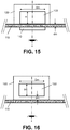
- the permanent magnet is an axially magnetised magnet arranged such that the axial direction of the magnet is substantially perpendicular to said rotation axis.
- the permanent magnet is a multipole disk magnet or a multipole ring magnet, magnetized in a plane substantially perpendicular to said rotation axis.
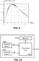
- the magnetic sensor device 130 may comprise a plurality of magnetic sensors (e.g. at least four Horizontal Hall elements, or at least two Vertical Hall elements) for measuring at least two magnetic field components (for example two in-plane magnetic field components Bx, By).
- This magnetic sensor device 130 may be configured for determining an absolute angular position ⁇ of the rotary button 120 based on said at least two measured field components.
- This embodiment offers the advantage that the angular position can be determine more accurately, over a larger range (e.g. 360°), and that it is more robust to ageing or demagnetisation of the magnet.
- buttons having an axially magnetized magnet with a cross section other than square or rectangular or circular can also be used.
- Suitable sensor devices are for example described in WO2014029885A1 , which document is incorporated herein in its entirety, especially the sections describing sensor arrangements for measuring the magnetic field at several locations and in particular directions, and the sections with formulas for calculating the angular position of a multipole magnet, more specifically for a quadrupole.
- suitable sensor devices typically comprise a plurality of sensor elements which are spaced apart, and which are oriented in predefined directions. The angular position can be calculated for example using on a arctan function of a ratio of difference signals. It is pointed out however, that the present invention is not limited only to the sensor devices described in WO2014029885A1 , and other suitable sensor devices may also be used.
- the multipole magnet 1722 is a four-pole magnet, also known as quadrupole, but the invention also works for magnets having more than four poles, for example having six or eight poles.
Landscapes
- Physics & Mathematics (AREA)
- General Physics & Mathematics (AREA)
- Condensed Matter Physics & Semiconductors (AREA)
- Engineering & Computer Science (AREA)
- Automation & Control Theory (AREA)
- Rotary Switch, Piano Key Switch, And Lever Switch (AREA)
- Transmission And Conversion Of Sensor Element Output (AREA)
- Switches With Compound Operations (AREA)
Claims (15)
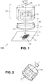
- Système de bouton rotatif (100) destiné à être utilisé dans un appareil domestique, comprenant :- une plaque ferromagnétique (110) ;- un bouton rotatif (120) pouvant être monté de manière amovible à une première distance prédéfinie (dm) de ladite plaque ferromagnétique (110) d'un premier côté de ladite plaque, et pouvant tourner autour d'un axe de rotation virtuel (105) sensiblement perpendiculaire à ladite plaque, et comprenant un aimant permanent (122) magnétisé dans une direction (X, Y) sensiblement perpendiculaire audit axe de rotation (105) ;- un dispositif de capteur magnétique (130) monté à une seconde distance prédéfinie (ds) de ladite plaque ferromagnétique (110) d'un second côté de ladite plaque opposé au premier côté ;- et le dispositif de capteur magnétique (130) comprenant au moins un capteur magnétique pour mesurer au moins une composante de champ magnétique (By) et étant configuré pour déterminer une position angulaire (a) du bouton rotatif (120) sur la base de ladite au moins une composante de champ magnétique (By), et/ou
le dispositif de capteur magnétique (130) comprenant au moins deux capteurs magnétiques, et étant configuré pour déterminer au moins un gradient de champ magnétique (dBx/dx), et étant configuré pour déterminer une position angulaire (a) du bouton rotatif (120) sur la base dudit au moins un gradient de champ magnétique. - Système de bouton rotatif (100) selon la revendication 1, le dispositif de capteur magnétique comprenant au moins deux capteurs magnétiques (HH1-HH4; VH1, VH2) pour mesurer au moins deux composantes de champ magnétique (Bx, By) dans des directions différentes (X, Y), et étant configuré pour déterminer une position angulaire (a) du bouton rotatif (120) sur la base desdites au moins deux composantes de champ magnétique (Bx, By).
- Système de bouton rotatif (100) selon la revendication 1 ou 2,
le dispositif de capteur magnétique (130) comprenant au moins quatre capteurs magnétiques pour mesurer au moins quatre composantes de champ magnétique, et étant configuré pour déterminer au moins deux gradients de champ magnétique (dBx/dx, dBy/dy) dans différentes directions (X, Y), et étant configuré pour déterminer une position angulaire (a) du bouton rotatif (120) sur la base desdits au moins deux gradients de champ magnétique. - Système de bouton rotatif (100) selon l'une quelconque des revendications précédentes, la plaque ferromagnétique (110) ayant une forme de disque.
- Système de bouton rotatif (100) selon l'une quelconque des revendications précédentes, la plaque ferromagnétique (110) ayant une forme rectangulaire.
- Système de bouton rotatif (100) selon l'une quelconque des revendications précédentes, la plaque ferromagnétique ayant une épaisseur (Tp) dans la plage de 0,3 à 1,0 mm.
- Système de bouton rotatif (100) selon l'une quelconque des revendications précédentes,
le dispositif de capteur magnétique (130) étant situé sensiblement sur ledit axe de rotation (105). - Système de bouton rotatif (100) selon l'une quelconque des revendications précédentes,
le dispositif de capteur de position magnétique (130) ayant une pluralité de capteurs magnétiques (HH1-HH4; VH1, VH2) configurés pour mesurer au moins deux composantes de champ magnétique dans le plan (Bx, By) dans des directions différentes (X, Y), et pour déterminer ladite position angulaire (a) sur la base desdites composantes de champ magnétique dans le plan (Bx, By). - Système de bouton rotatif (100) selon l'une quelconque des revendications précédentes,
le dispositif de capteur magnétique (130) comprenant au moins un premier élément à effet Hall vertical (VH1) ayant un premier axe de sensibilité maximale dans une première direction (X), et un second élément à effet Hall vertical (VH2) ayant un second axe de sensibilité maximale parallèle dans une seconde direction (Y), la première et la seconde direction étant sensiblement parallèles à ladite plaque ferromagnétique (110). - Système de bouton rotatif (100) selon l'une quelconque des revendications précédentes,
le dispositif de capteur magnétique (130) comprenant au moins quatre éléments à effet Hall horizontaux (HH1-HH4) et au moins un concentrateur magnétique intégré (510). - Système de bouton rotatif (100) selon l'une quelconque des revendications précédentes,
l'aimant permanent (122 ; 1222 ; 1322 ; 1422) étant l'un des éléments suivants :- un aimant à disque diamétralement magnétisé (122), agencé sensiblement de manière coaxiale avec ledit axe de rotation (105) ;- un aimant annulaire diamétralement magnétisé (1322) agencé sensiblement de manière coaxiale avec ledit axe de rotation (1305) ;- un aimant axialement magnétisé (1422) agencé de telle sorte que la direction axiale de l'aimant est sensiblement perpendiculaire audit axe de rotation (1405) ;- un aimant à disque multipolaire (1722) ou un aimant annulaire multipolaire, magnétisé dans un plan sensiblement perpendiculaire audit axe de rotation (105). - Système de bouton rotatif (100) selon l'une quelconque des revendications précédentes,
l'aimant (122) étant un aimant à disque diamétralement magnétisé ayant un diamètre (Dm) dans la plage de 4 à 14 mm ;
ou l'aimant (122) étant un aimant annulaire multipolaire ou un aimant à disque multipolaire (1722) ayant un diamètre (Dm) dans la plage de 4 à 14 mm ;
ou l'aimant (122) étant un aimant axialement magnétisé ayant une longueur axiale (Lm) dans la plage de 4 à 14 mm. - Système de bouton rotatif (100) selon l'une quelconque des revendications précédentes, la seconde distance (ds) entre le dispositif de capteur magnétique (130) et la plaque ferromagnétique (110) étant une valeur dans la plage de 0,5 à 6,5 mm.
- Système de bouton rotatif (100) selon l'une quelconque des revendications précédentes,
l'aimant (122) étant un aimant à disque diamétralement magnétisé ayant un diamètre (Dm) dans la plage de 4 à 14 mm, ou un aimant axialement magnétisé ayant une longueur axiale (Lm) dans la plage de 4 à 14 mm ;
et la première distance (dm) entre la plaque ferromagnétique (110) et l'aimant (122) étant une valeur dans la plage de 0,5 à 1,5 mm ;
et la plaque ferromagnétique (110) ayant une épaisseur (Tp) dans la plage de 0,3 à 1,0 mm ;
et la seconde distance (ds) entre la plaque ferromagnétique (110) et le dispositif de capteur magnétique (130) étant une valeur dans la plage de 1,0 à 4,5 mm. - Système de bouton rotatif (100) selon l'une quelconque des revendications précédentes,
le dispositif de capteur magnétique (130) comprenant au moins un capteur magnétique pour mesurer ladite au moins une composante de champ magnétique, et étant en outre configuré pour déterminer une présence du bouton à ladite distance prédéfinie de la plaque ferromagnétique en comparant une amplitude de ladite au moins une composante de champ magnétique avec un seuil prédéfini ;
ou le dispositif de capteur magnétique (130) comprenant au moins deux capteurs magnétiques, et étant en outre configuré pour déterminer une présence du bouton à ladite distance prédéfinie de la plaque ferromagnétique en vérifiant qu'au moins une des composantes de champ magnétique fournies par ces capteurs est supérieure à un seuil prédéfini ;
ou le dispositif de capteur magnétique (130) comprenant au moins deux capteurs magnétiques agencés en quadrature, et étant en outre configuré pour déterminer une présence du bouton à ladite distance prédéfinie de la plaque ferromagnétique en comparant une somme de carrés des composantes de champ magnétique fournies par ces capteurs avec un seuil prédéfini.
Priority Applications (3)
| Application Number | Priority Date | Filing Date | Title |
|---|---|---|---|
| EP19154032.7A EP3686560B1 (fr) | 2019-01-28 | 2019-01-28 | Système de bouton rotatif à attraction magnétique |
| CN202010048008.0A CN111488030B (zh) | 2019-01-28 | 2020-01-16 | 磁性吸引旋转式按钮系统 |
| US16/745,972 US11257643B2 (en) | 2019-01-28 | 2020-01-17 | Magnetic attractive rotary button system |
Applications Claiming Priority (1)
| Application Number | Priority Date | Filing Date | Title |
|---|---|---|---|
| EP19154032.7A EP3686560B1 (fr) | 2019-01-28 | 2019-01-28 | Système de bouton rotatif à attraction magnétique |
Publications (2)
| Publication Number | Publication Date |
|---|---|
| EP3686560A1 EP3686560A1 (fr) | 2020-07-29 |
| EP3686560B1 true EP3686560B1 (fr) | 2021-07-14 |
Family
ID=65241189
Family Applications (1)
| Application Number | Title | Priority Date | Filing Date |
|---|---|---|---|
| EP19154032.7A Active EP3686560B1 (fr) | 2019-01-28 | 2019-01-28 | Système de bouton rotatif à attraction magnétique |
Country Status (3)
| Country | Link |
|---|---|
| US (1) | US11257643B2 (fr) |
| EP (1) | EP3686560B1 (fr) |
| CN (1) | CN111488030B (fr) |
Families Citing this family (7)
| Publication number | Priority date | Publication date | Assignee | Title |
|---|---|---|---|---|
| GB2540599B (en) * | 2015-07-22 | 2021-04-14 | Cmr Surgical Ltd | Rotary encoder. |
| EP3875915B1 (fr) * | 2020-03-06 | 2023-07-19 | Melexis Technologies SA | Dispositif, système et procédé de détermination de la position d'un aimant |
| EP4105768B1 (fr) * | 2021-06-18 | 2024-03-06 | Melexis Technologies SA | Dispositif et procédé pour déterminer l'orientation d'un aimant et manette de jeu |
| EP4194815B1 (fr) * | 2021-12-10 | 2024-06-05 | Melexis Technologies SA | Ensemble capteur doté d'une manette de jeu ou d'un stick analogique |
| DE102023133062A1 (de) * | 2023-11-27 | 2025-05-28 | Nexopart GmbH & Co. KG | Labormühle mit Bediengruppe |
| US20250174216A1 (en) * | 2023-11-28 | 2025-05-29 | Fender Musical Instruments Corporation | Systems and methods for modifying musical signals |
| US20260031643A1 (en) * | 2024-07-23 | 2026-01-29 | Anker Innovations Technology Co., Ltd. | Charger, charging control circuit, and method for controlling a charger |
Family Cites Families (17)
| Publication number | Priority date | Publication date | Assignee | Title |
|---|---|---|---|---|
| US5880586A (en) | 1994-11-22 | 1999-03-09 | Robert Bosch Gmbh | Apparatus for determining rotational position of a rotatable element without contacting it |
| US6556005B1 (en) * | 2000-01-27 | 2003-04-29 | Goodrich Avionics Systems, Inc. | Magnetic encoder apparatus capable of resolving axial and rotational displacements |
| EP1610095B1 (fr) * | 2004-06-21 | 2016-08-10 | Baumer Electric AG | Capteur de rotation pour déterminer la position angulaire absolue d'un arbre |
| US8901921B2 (en) * | 2009-11-25 | 2014-12-02 | Infineon Technologies Ag | Angle measurement system for determining an angular position of a rotating shaft |
| GB2505226A (en) | 2012-08-23 | 2014-02-26 | Melexis Technologies Nv | Arrangement, method and sensor for measuring an absolute angular position using a multi-pole magnet |
| CN103591969B (zh) * | 2012-08-28 | 2016-01-20 | 王嘉 | 具有内置磁铁盘的防水编码装置 |
| DE102013219018A1 (de) * | 2012-12-20 | 2014-06-26 | Continental Teves Ag & Co. Ohg | Winkelsensors |
| US9671214B2 (en) * | 2013-07-17 | 2017-06-06 | Infineon Technologies Ag | Discrete magnetic angle sensor device, a magnetic angle sensor arrangement, a method for generating an angle signal and a method for providing a sensor signal |
| US10024690B2 (en) * | 2015-04-14 | 2018-07-17 | Texas Instruments Incorporated | Incremental rotary encoder using hall effect sensors and magnetic detents |
| CN204731676U (zh) * | 2015-07-13 | 2015-10-28 | 浙江绍兴苏泊尔生活电器有限公司 | 调节旋钮及电器产品 |
| CN105281732B (zh) | 2015-10-19 | 2018-04-17 | 宁波方太厨具有限公司 | 一种感应式开关旋钮及其编码方法 |
| US10269515B2 (en) * | 2016-09-08 | 2019-04-23 | Touchsensor Technologies, Llc | Magnetic encoder knob with fixed center |
| EP3321638B1 (fr) | 2016-11-14 | 2019-03-06 | Melexis Technologies SA | Mesure de position angulaire absolue |
| EP3367067B1 (fr) * | 2017-02-28 | 2019-07-03 | Melexis Technologies SA | Capteur de position et procédé de détection de position |
| EP3385678B1 (fr) * | 2017-04-06 | 2021-07-28 | Melexis Technologies SA | Capteur de position de rotation |
| US10903030B2 (en) * | 2017-04-27 | 2021-01-26 | Magswitch Technology Worldwide Pty Ltd. | Variable field magnetic couplers and methods for engaging a ferromagnetic workpiece |
| EP3415871A1 (fr) * | 2017-06-12 | 2018-12-19 | Fraba B.V. | Système de capteur destiné à détecter des lignes d'un champ magnétique ou d'un système de détection ou d'un système de mesure d'angle de rotation |
-
2019
- 2019-01-28 EP EP19154032.7A patent/EP3686560B1/fr active Active
-
2020
- 2020-01-16 CN CN202010048008.0A patent/CN111488030B/zh active Active
- 2020-01-17 US US16/745,972 patent/US11257643B2/en active Active
Also Published As
| Publication number | Publication date |
|---|---|
| US11257643B2 (en) | 2022-02-22 |
| EP3686560A1 (fr) | 2020-07-29 |
| US20200243285A1 (en) | 2020-07-30 |
| CN111488030B (zh) | 2022-08-02 |
| CN111488030A (zh) | 2020-08-04 |
Similar Documents
| Publication | Publication Date | Title |
|---|---|---|
| EP3686560B1 (fr) | Système de bouton rotatif à attraction magnétique | |
| US20220276072A1 (en) | Magnetic sensor device, system and method | |
| US11506517B2 (en) | Magnetic angular position sensor | |
| EP3184954B1 (fr) | Capteur d'angle magnéto-résistif | |
| US10533877B2 (en) | Angle sensor with disturbance field suppression | |
| US10732009B2 (en) | Angle sensing in an off-axis configuration | |
| CN103968860B (zh) | 绝对式磁旋转编码器 | |
| US20200217690A1 (en) | Angle sensor bridges including star-connected magnetoresistive elements | |
| US20040017187A1 (en) | Magnetoresistive linear position sensor | |
| CN103529267A (zh) | 用于测量电流的电流变换器 | |
| EP2988279A1 (fr) | Tête magnétique pour détecter un champ magnétique sur la surface d'un motif magnétique, basée sur une technologie à magnéto résistance | |
| US9268001B2 (en) | Differential perpendicular on-axis angle sensor | |
| US9958511B2 (en) | Soft switching of magnetization in a magnetoresistive sensor | |
| CN106066461B (zh) | 磁阻装置 | |
| US20150160307A1 (en) | Orthogonal fluxgate sensor | |
| US9697940B2 (en) | Apparatus and methods for generating a uniform magnetic field | |
| CN103988086B (zh) | 感测电流的装置和方法 | |
| US20240248157A1 (en) | Magnetic sensor and magnetic detection system | |
| KR20230101134A (ko) | 스핀 궤도 결합 토크를 이용한 자기 센서 및 그것을 이용한 센싱 방법 | |
| US20210131827A1 (en) | Shaft rotation angle detection | |
| JP2008014954A (ja) | 磁気センサ | |
| JP2004037236A (ja) | 回転角度検出装置 | |
| EP4705733A1 (fr) | Dispositif, système et procédé de capteur de couple | |
| TW201037337A (en) | Testing system and method for electronic compass |
Legal Events
| Date | Code | Title | Description |
|---|---|---|---|
| PUAI | Public reference made under article 153(3) epc to a published international application that has entered the european phase |
Free format text: ORIGINAL CODE: 0009012 |
|
| STAA | Information on the status of an ep patent application or granted ep patent |
Free format text: STATUS: THE APPLICATION HAS BEEN PUBLISHED |
|
| AK | Designated contracting states |
Kind code of ref document: A1 Designated state(s): AL AT BE BG CH CY CZ DE DK EE ES FI FR GB GR HR HU IE IS IT LI LT LU LV MC MK MT NL NO PL PT RO RS SE SI SK SM TR |
|
| AX | Request for extension of the european patent |
Extension state: BA ME |
|
| STAA | Information on the status of an ep patent application or granted ep patent |
Free format text: STATUS: REQUEST FOR EXAMINATION WAS MADE |
|
| 17P | Request for examination filed |
Effective date: 20210120 |
|
| RBV | Designated contracting states (corrected) |
Designated state(s): AL AT BE BG CH CY CZ DE DK EE ES FI FR GB GR HR HU IE IS IT LI LT LU LV MC MK MT NL NO PL PT RO RS SE SI SK SM TR |
|
| GRAP | Despatch of communication of intention to grant a patent |
Free format text: ORIGINAL CODE: EPIDOSNIGR1 |
|
| STAA | Information on the status of an ep patent application or granted ep patent |
Free format text: STATUS: GRANT OF PATENT IS INTENDED |
|
| INTG | Intention to grant announced |
Effective date: 20210226 |
|
| RIN1 | Information on inventor provided before grant (corrected) |
Inventor name: WANG, HAO |
|
| GRAS | Grant fee paid |
Free format text: ORIGINAL CODE: EPIDOSNIGR3 |
|
| GRAJ | Information related to disapproval of communication of intention to grant by the applicant or resumption of examination proceedings by the epo deleted |
Free format text: ORIGINAL CODE: EPIDOSDIGR1 |
|
| GRAL | Information related to payment of fee for publishing/printing deleted |
Free format text: ORIGINAL CODE: EPIDOSDIGR3 |
|
| STAA | Information on the status of an ep patent application or granted ep patent |
Free format text: STATUS: REQUEST FOR EXAMINATION WAS MADE |
|
| GRAP | Despatch of communication of intention to grant a patent |
Free format text: ORIGINAL CODE: EPIDOSNIGR1 |
|
| STAA | Information on the status of an ep patent application or granted ep patent |
Free format text: STATUS: GRANT OF PATENT IS INTENDED |
|
| INTC | Intention to grant announced (deleted) | ||
| GRAA | (expected) grant |
Free format text: ORIGINAL CODE: 0009210 |
|
| STAA | Information on the status of an ep patent application or granted ep patent |
Free format text: STATUS: THE PATENT HAS BEEN GRANTED |
|
| INTG | Intention to grant announced |
Effective date: 20210526 |
|
| AK | Designated contracting states |
Kind code of ref document: B1 Designated state(s): AL AT BE BG CH CY CZ DE DK EE ES FI FR GB GR HR HU IE IS IT LI LT LU LV MC MK MT NL NO PL PT RO RS SE SI SK SM TR |
|
| REG | Reference to a national code |
Ref country code: GB Ref legal event code: FG4D |
|
| REG | Reference to a national code |
Ref country code: DE Ref legal event code: R096 Ref document number: 602019006000 Country of ref document: DE |
|
| REG | Reference to a national code |
Ref country code: IE Ref legal event code: FG4D |
|
| REG | Reference to a national code |
Ref country code: AT Ref legal event code: REF Ref document number: 1411004 Country of ref document: AT Kind code of ref document: T Effective date: 20210815 |
|
| REG | Reference to a national code |
Ref country code: LT Ref legal event code: MG9D |
|
| REG | Reference to a national code |
Ref country code: NL Ref legal event code: MP Effective date: 20210714 |
|
| REG | Reference to a national code |
Ref country code: AT Ref legal event code: MK05 Ref document number: 1411004 Country of ref document: AT Kind code of ref document: T Effective date: 20210714 |
|
| PG25 | Lapsed in a contracting state [announced via postgrant information from national office to epo] |
Ref country code: ES Free format text: LAPSE BECAUSE OF FAILURE TO SUBMIT A TRANSLATION OF THE DESCRIPTION OR TO PAY THE FEE WITHIN THE PRESCRIBED TIME-LIMIT Effective date: 20210714 Ref country code: FI Free format text: LAPSE BECAUSE OF FAILURE TO SUBMIT A TRANSLATION OF THE DESCRIPTION OR TO PAY THE FEE WITHIN THE PRESCRIBED TIME-LIMIT Effective date: 20210714 Ref country code: RS Free format text: LAPSE BECAUSE OF FAILURE TO SUBMIT A TRANSLATION OF THE DESCRIPTION OR TO PAY THE FEE WITHIN THE PRESCRIBED TIME-LIMIT Effective date: 20210714 Ref country code: SE Free format text: LAPSE BECAUSE OF FAILURE TO SUBMIT A TRANSLATION OF THE DESCRIPTION OR TO PAY THE FEE WITHIN THE PRESCRIBED TIME-LIMIT Effective date: 20210714 Ref country code: NO Free format text: LAPSE BECAUSE OF FAILURE TO SUBMIT A TRANSLATION OF THE DESCRIPTION OR TO PAY THE FEE WITHIN THE PRESCRIBED TIME-LIMIT Effective date: 20211014 Ref country code: PT Free format text: LAPSE BECAUSE OF FAILURE TO SUBMIT A TRANSLATION OF THE DESCRIPTION OR TO PAY THE FEE WITHIN THE PRESCRIBED TIME-LIMIT Effective date: 20211115 Ref country code: NL Free format text: LAPSE BECAUSE OF FAILURE TO SUBMIT A TRANSLATION OF THE DESCRIPTION OR TO PAY THE FEE WITHIN THE PRESCRIBED TIME-LIMIT Effective date: 20210714 Ref country code: HR Free format text: LAPSE BECAUSE OF FAILURE TO SUBMIT A TRANSLATION OF THE DESCRIPTION OR TO PAY THE FEE WITHIN THE PRESCRIBED TIME-LIMIT Effective date: 20210714 Ref country code: BG Free format text: LAPSE BECAUSE OF FAILURE TO SUBMIT A TRANSLATION OF THE DESCRIPTION OR TO PAY THE FEE WITHIN THE PRESCRIBED TIME-LIMIT Effective date: 20211014 Ref country code: AT Free format text: LAPSE BECAUSE OF FAILURE TO SUBMIT A TRANSLATION OF THE DESCRIPTION OR TO PAY THE FEE WITHIN THE PRESCRIBED TIME-LIMIT Effective date: 20210714 Ref country code: LT Free format text: LAPSE BECAUSE OF FAILURE TO SUBMIT A TRANSLATION OF THE DESCRIPTION OR TO PAY THE FEE WITHIN THE PRESCRIBED TIME-LIMIT Effective date: 20210714 |
|
| PG25 | Lapsed in a contracting state [announced via postgrant information from national office to epo] |
Ref country code: PL Free format text: LAPSE BECAUSE OF FAILURE TO SUBMIT A TRANSLATION OF THE DESCRIPTION OR TO PAY THE FEE WITHIN THE PRESCRIBED TIME-LIMIT Effective date: 20210714 Ref country code: LV Free format text: LAPSE BECAUSE OF FAILURE TO SUBMIT A TRANSLATION OF THE DESCRIPTION OR TO PAY THE FEE WITHIN THE PRESCRIBED TIME-LIMIT Effective date: 20210714 Ref country code: GR Free format text: LAPSE BECAUSE OF FAILURE TO SUBMIT A TRANSLATION OF THE DESCRIPTION OR TO PAY THE FEE WITHIN THE PRESCRIBED TIME-LIMIT Effective date: 20211015 |
|
| REG | Reference to a national code |
Ref country code: DE Ref legal event code: R097 Ref document number: 602019006000 Country of ref document: DE |
|
| PG25 | Lapsed in a contracting state [announced via postgrant information from national office to epo] |
Ref country code: DK Free format text: LAPSE BECAUSE OF FAILURE TO SUBMIT A TRANSLATION OF THE DESCRIPTION OR TO PAY THE FEE WITHIN THE PRESCRIBED TIME-LIMIT Effective date: 20210714 |
|
| PLBE | No opposition filed within time limit |
Free format text: ORIGINAL CODE: 0009261 |
|
| STAA | Information on the status of an ep patent application or granted ep patent |
Free format text: STATUS: NO OPPOSITION FILED WITHIN TIME LIMIT |
|
| PG25 | Lapsed in a contracting state [announced via postgrant information from national office to epo] |
Ref country code: SM Free format text: LAPSE BECAUSE OF FAILURE TO SUBMIT A TRANSLATION OF THE DESCRIPTION OR TO PAY THE FEE WITHIN THE PRESCRIBED TIME-LIMIT Effective date: 20210714 Ref country code: SK Free format text: LAPSE BECAUSE OF FAILURE TO SUBMIT A TRANSLATION OF THE DESCRIPTION OR TO PAY THE FEE WITHIN THE PRESCRIBED TIME-LIMIT Effective date: 20210714 Ref country code: RO Free format text: LAPSE BECAUSE OF FAILURE TO SUBMIT A TRANSLATION OF THE DESCRIPTION OR TO PAY THE FEE WITHIN THE PRESCRIBED TIME-LIMIT Effective date: 20210714 Ref country code: EE Free format text: LAPSE BECAUSE OF FAILURE TO SUBMIT A TRANSLATION OF THE DESCRIPTION OR TO PAY THE FEE WITHIN THE PRESCRIBED TIME-LIMIT Effective date: 20210714 Ref country code: CZ Free format text: LAPSE BECAUSE OF FAILURE TO SUBMIT A TRANSLATION OF THE DESCRIPTION OR TO PAY THE FEE WITHIN THE PRESCRIBED TIME-LIMIT Effective date: 20210714 Ref country code: AL Free format text: LAPSE BECAUSE OF FAILURE TO SUBMIT A TRANSLATION OF THE DESCRIPTION OR TO PAY THE FEE WITHIN THE PRESCRIBED TIME-LIMIT Effective date: 20210714 |
|
| 26N | No opposition filed |
Effective date: 20220419 |
|
| PG25 | Lapsed in a contracting state [announced via postgrant information from national office to epo] |
Ref country code: IT Free format text: LAPSE BECAUSE OF FAILURE TO SUBMIT A TRANSLATION OF THE DESCRIPTION OR TO PAY THE FEE WITHIN THE PRESCRIBED TIME-LIMIT Effective date: 20210714 |
|
| PG25 | Lapsed in a contracting state [announced via postgrant information from national office to epo] |
Ref country code: MC Free format text: LAPSE BECAUSE OF FAILURE TO SUBMIT A TRANSLATION OF THE DESCRIPTION OR TO PAY THE FEE WITHIN THE PRESCRIBED TIME-LIMIT Effective date: 20210714 |
|
| REG | Reference to a national code |
Ref country code: CH Ref legal event code: PL |
|
| REG | Reference to a national code |
Ref country code: BE Ref legal event code: MM Effective date: 20220131 |
|
| PG25 | Lapsed in a contracting state [announced via postgrant information from national office to epo] |
Ref country code: LU Free format text: LAPSE BECAUSE OF NON-PAYMENT OF DUE FEES Effective date: 20220128 |
|
| PG25 | Lapsed in a contracting state [announced via postgrant information from national office to epo] |
Ref country code: BE Free format text: LAPSE BECAUSE OF NON-PAYMENT OF DUE FEES Effective date: 20220131 |
|
| PG25 | Lapsed in a contracting state [announced via postgrant information from national office to epo] |
Ref country code: LI Free format text: LAPSE BECAUSE OF NON-PAYMENT OF DUE FEES Effective date: 20220131 Ref country code: CH Free format text: LAPSE BECAUSE OF NON-PAYMENT OF DUE FEES Effective date: 20220131 |
|
| PG25 | Lapsed in a contracting state [announced via postgrant information from national office to epo] |
Ref country code: IE Free format text: LAPSE BECAUSE OF NON-PAYMENT OF DUE FEES Effective date: 20220128 |
|
| P01 | Opt-out of the competence of the unified patent court (upc) registered |
Effective date: 20230517 |
|
| GBPC | Gb: european patent ceased through non-payment of renewal fee |
Effective date: 20230128 |
|
| PG25 | Lapsed in a contracting state [announced via postgrant information from national office to epo] |
Ref country code: GB Free format text: LAPSE BECAUSE OF NON-PAYMENT OF DUE FEES Effective date: 20230128 |
|
| PG25 | Lapsed in a contracting state [announced via postgrant information from national office to epo] |
Ref country code: MK Free format text: LAPSE BECAUSE OF FAILURE TO SUBMIT A TRANSLATION OF THE DESCRIPTION OR TO PAY THE FEE WITHIN THE PRESCRIBED TIME-LIMIT Effective date: 20210714 Ref country code: CY Free format text: LAPSE BECAUSE OF FAILURE TO SUBMIT A TRANSLATION OF THE DESCRIPTION OR TO PAY THE FEE WITHIN THE PRESCRIBED TIME-LIMIT Effective date: 20210714 |
|
| PG25 | Lapsed in a contracting state [announced via postgrant information from national office to epo] |
Ref country code: HU Free format text: LAPSE BECAUSE OF FAILURE TO SUBMIT A TRANSLATION OF THE DESCRIPTION OR TO PAY THE FEE WITHIN THE PRESCRIBED TIME-LIMIT; INVALID AB INITIO Effective date: 20190128 |
|
| PG25 | Lapsed in a contracting state [announced via postgrant information from national office to epo] |
Ref country code: MT Free format text: LAPSE BECAUSE OF FAILURE TO SUBMIT A TRANSLATION OF THE DESCRIPTION OR TO PAY THE FEE WITHIN THE PRESCRIBED TIME-LIMIT Effective date: 20210714 |
|
| PG25 | Lapsed in a contracting state [announced via postgrant information from national office to epo] |
Ref country code: TR Free format text: LAPSE BECAUSE OF FAILURE TO SUBMIT A TRANSLATION OF THE DESCRIPTION OR TO PAY THE FEE WITHIN THE PRESCRIBED TIME-LIMIT Effective date: 20210714 |
|
| PGFP | Annual fee paid to national office [announced via postgrant information from national office to epo] |
Ref country code: FR Payment date: 20251217 Year of fee payment: 8 |
|
| PGFP | Annual fee paid to national office [announced via postgrant information from national office to epo] |
Ref country code: DE Payment date: 20251217 Year of fee payment: 8 |