EP3686572B1 - Reifenprüfvorrichtung - Google Patents
Reifenprüfvorrichtung Download PDFInfo
- Publication number
- EP3686572B1 EP3686572B1 EP19862009.8A EP19862009A EP3686572B1 EP 3686572 B1 EP3686572 B1 EP 3686572B1 EP 19862009 A EP19862009 A EP 19862009A EP 3686572 B1 EP3686572 B1 EP 3686572B1
- Authority
- EP
- European Patent Office
- Prior art keywords
- tire
- ground contact
- contact surface
- processing unit
- image information
- Prior art date
- Legal status (The legal status is an assumption and is not a legal conclusion. Google has not performed a legal analysis and makes no representation as to the accuracy of the status listed.)
- Active
Links
Images


Classifications
-
- G—PHYSICS
- G01—MEASURING; TESTING
- G01M—TESTING STATIC OR DYNAMIC BALANCE OF MACHINES OR STRUCTURES; TESTING OF STRUCTURES OR APPARATUS, NOT OTHERWISE PROVIDED FOR
- G01M17/00—Testing of vehicles
- G01M17/007—Wheeled or endless-tracked vehicles
- G01M17/02—Tyres
- G01M17/022—Tyres the tyre co-operating with rotatable rolls
-
- B—PERFORMING OPERATIONS; TRANSPORTING
- B60—VEHICLES IN GENERAL
- B60C—VEHICLE TYRES; TYRE INFLATION; TYRE CHANGING; CONNECTING VALVES TO INFLATABLE ELASTIC BODIES IN GENERAL; DEVICES OR ARRANGEMENTS RELATED TO TYRES
- B60C11/00—Tyre tread bands; Tread patterns; Anti-skid inserts
- B60C11/03—Tread patterns
- B60C11/0327—Tread patterns characterised by special properties of the tread pattern
- B60C11/0332—Tread patterns characterised by special properties of the tread pattern by the footprint-ground contacting area of the tyre tread
-
- B—PERFORMING OPERATIONS; TRANSPORTING
- B60—VEHICLES IN GENERAL
- B60C—VEHICLE TYRES; TYRE INFLATION; TYRE CHANGING; CONNECTING VALVES TO INFLATABLE ELASTIC BODIES IN GENERAL; DEVICES OR ARRANGEMENTS RELATED TO TYRES
- B60C99/00—Subject matter not provided for in other groups of this subclass
-
- G—PHYSICS
- G01—MEASURING; TESTING
- G01B—MEASURING LENGTH, THICKNESS OR SIMILAR LINEAR DIMENSIONS; MEASURING ANGLES; MEASURING AREAS; MEASURING IRREGULARITIES OF SURFACES OR CONTOURS
- G01B11/00—Measuring arrangements characterised by the use of optical techniques
- G01B11/24—Measuring arrangements characterised by the use of optical techniques for measuring contours or curvatures
-
- G—PHYSICS
- G01—MEASURING; TESTING
- G01L—MEASURING FORCE, STRESS, TORQUE, WORK, MECHANICAL POWER, MECHANICAL EFFICIENCY, OR FLUID PRESSURE
- G01L5/00—Apparatus for, or methods of, measuring force, work, mechanical power, or torque, specially adapted for specific purposes
- G01L5/16—Apparatus for, or methods of, measuring force, work, mechanical power, or torque, specially adapted for specific purposes for measuring several components of force
-
- G—PHYSICS
- G01—MEASURING; TESTING
- G01M—TESTING STATIC OR DYNAMIC BALANCE OF MACHINES OR STRUCTURES; TESTING OF STRUCTURES OR APPARATUS, NOT OTHERWISE PROVIDED FOR
- G01M17/00—Testing of vehicles
- G01M17/007—Wheeled or endless-tracked vehicles
- G01M17/02—Tyres
- G01M17/027—Tyres using light, e.g. infrared, ultraviolet or holographic techniques
-
- G—PHYSICS
- G06—COMPUTING OR CALCULATING; COUNTING
- G06T—IMAGE DATA PROCESSING OR GENERATION, IN GENERAL
- G06T7/00—Image analysis
- G06T7/0002—Inspection of images, e.g. flaw detection
- G06T7/0004—Industrial image inspection
-
- G—PHYSICS
- G06—COMPUTING OR CALCULATING; COUNTING
- G06T—IMAGE DATA PROCESSING OR GENERATION, IN GENERAL
- G06T7/00—Image analysis
- G06T7/0002—Inspection of images, e.g. flaw detection
- G06T7/0004—Industrial image inspection
- G06T7/001—Industrial image inspection using an image reference approach
-
- G—PHYSICS
- G06—COMPUTING OR CALCULATING; COUNTING
- G06T—IMAGE DATA PROCESSING OR GENERATION, IN GENERAL
- G06T7/00—Image analysis
- G06T7/10—Segmentation; Edge detection
-
- G—PHYSICS
- G06—COMPUTING OR CALCULATING; COUNTING
- G06T—IMAGE DATA PROCESSING OR GENERATION, IN GENERAL
- G06T7/00—Image analysis
- G06T7/10—Segmentation; Edge detection
- G06T7/12—Edge-based segmentation
-
- G—PHYSICS
- G06—COMPUTING OR CALCULATING; COUNTING
- G06T—IMAGE DATA PROCESSING OR GENERATION, IN GENERAL
- G06T2207/00—Indexing scheme for image analysis or image enhancement
- G06T2207/20—Special algorithmic details
- G06T2207/20021—Dividing image into blocks, subimages or windows
-
- G—PHYSICS
- G06—COMPUTING OR CALCULATING; COUNTING
- G06T—IMAGE DATA PROCESSING OR GENERATION, IN GENERAL
- G06T2207/00—Indexing scheme for image analysis or image enhancement
- G06T2207/30—Subject of image; Context of image processing
- G06T2207/30108—Industrial image inspection
Definitions
- the present invention relates to a tire testing apparatus.
- a wear test of a tire for use in an automobile and the like is performed by multiplying a force (ground contact force) applied to the tire and a slip amount of the tire by each other to calculate wear energy. Then, heretofore, measurement of the ground contact force has been performed, for example, by embedding a sensor for measuring the ground contact force in a road surface. Moreover, the slip amount has been obtained by imaging a ground contact surface of the tire and performing image processing therefor.
- Patent Literature 1 described below is present.
- Patent Literature 1 a camera and a transparent round bar are embedded in a road surface, and a pressure sensor is installed around the round bar, whereby the measurement of the ground contact force and the imaging of the ground contact surface of the tire are performed.
- Patent Literature 1 JP 2005-214860 A
- Patent Literature 1 a part of an imaged image is modeled, and a range in which the part is modeled is subjected to pattern matching, whereby a slip amount is specified.
- a range in which the part is modeled is subjected to pattern matching, whereby a slip amount is specified.
- it is difficult to set the range in which the part is modeled while such range setting is manually performed by an operator or the like.
- Another device known from CN 108 225 798 comprises a tire slip amount test system that detects the slip amount based on the displacement of marking points that are physically sprayed on selected positions of the tire tread. It has a test platform provided with a glass table plate that is arranged in a frame.
- the frame is connected with a tire that is connected with a rolling control mechanism.
- a side wall of the frame is provided with a laser corresponding to the front and rear of tire rolling direction.
- a circle of a LED illumination lamp is arranged in the glass table plate to surround a contact surface of the tire and the glass table plate.
- a camera is arranged in the contact surface of the tire and the glass table plate.
- a workstation is connected with the LED illumination lamp. The camera data receives image data and processes a data display.
- a first invention is a tire testing apparatus of a drum type according to claim 1.
- division processing at the time of performing such image information matching processing for calculating the slip amount can be set automatically and appropriately.
- the division processing unit can be configured like a tire testing apparatus that divides the image information subjected to the edging processing into regions with a predetermined size, and in each of the divided regions, performs processing for repeating the division of the region until the number of bright spot pixels in the region becomes less than a predetermined threshold value.
- the matching processing is performed by using the edged image information. Therefore, when the number of bright spot pixels does not satisfy a predetermined condition regarding the bright spot pixels, for example, is a predetermined threshold value or more, then a desired resolution is not obtained. Therefore, in order to obtain the desired resolution, it is preferable to repeat the division of the regions until the bright spot pixels satisfy the predetermined condition.
- the matching processing unit can be configured like a tire testing apparatus that performs matching processing for matching the divided region and image information of the ground contact surface of the tire with each other, the image information being subjected to the edging processing at different time from the divided region.
- slips from a tread start to a kickout can be matched in a time series, and accordingly, an influence of a tire curvature radius is less liable to be given, and a calculation error of the slip amount can be reduced.
- the slip amount calculation processing unit can be configured like a tire testing apparatus that: computes a coordinate of a point at a predetermined position in the divided region and a coordinate of a corresponding point in the matched region and thereby calculates a displacement; and calculates the slip amount by using the calculated displacement.
- a computer program of the present invention according to claim 4 is disclosed.
- the range in which such image pattern matching for calculating the slip amount of the tire can be set automatically and appropriately.
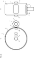
- FIG. 1 An example of an exterior appearance of a tire testing apparatus 1 of the present invention is illustrated in Fig. 1 .
- Fig. 2 An enlarged view of a vicinity of a sensor installation portion for performing measurement of a ground contact force, the sensor installation portion going to be described later, is illustrated in Fig. 2 .
- the tire testing apparatus 1 is a drum-type testing apparatus for measuring a ground contact force of a tire 5 and imaging a ground contact surface of the tire 5.
- the tire testing apparatus 1 performs a test by bringing the tire 5 as a test target into ground contact with an outer circumferential surface (drum surface) of a drum 10 that rotates about a drum shaft 13.
- a part of the drum surface is provided with: the sensor installation portion including a sensor for measuring a ground contact force of the tire 5; and a transmission portion 11 for performing imaging by an imaging device 14.
- a plurality of, for example, approximately eighty 3-component force sensors 12a sensors 12a which measure forces in the respective directions of an X-axis, a Y-axis and a Z-axis
- the drum 10 rotates about the drum shaft 13, whereby a surface (ground contact surface) of the tire 5 is brought into ground contact with the sensors 12a of the sensor installation portion 12, and the measurement of the ground contact force of the tire 5 is thereby performed.
- the 3-component force sensors 12a for example, Force Matrix Sensors (FMSs) manufactured by the applicant can be used.
- FMSs Force Matrix Sensors
- a portion from an inside of the drum 10 to an outside thereof be composed of a transparent material so that the imaging device 14 is capable of imaging the ground contact surface of the tire 5, which is brought into ground contact with the transmission portion 11.
- a transparent material for example, reinforced glass, reinforced plastics and the like are mentioned; however, the transmission portion 11 is not limited to these.
- a friction coefficient of the transmission portion 11 it is preferable to use a material with a friction coefficient same as or approximate to that of the drum surface.
- the imaging device 14 that images the ground contact surface of the tire 5 via the transmission portion 11 is provided.
- a lens of the imaging device 14 is fixed in advance onto a diameter, which connects the drum shaft 13 and the transmission portion 11 to each other, so as to be directed toward the transmission portion 11, and a tire surface of the tire, which is brought into ground contact with the transmission portion 11, is imaged from the inside of the housing of the drum 10 via the transmission portion 11.
- a reflecting member such as a mirror is provided in the inside of the housing of the drum 10, and that the imaging device 14 images the ground contact surface of the tire 5 via the reflecting member and the transmission portion 11.
- the tire testing apparatus 1 includes a tire support mechanism that supports the tire 5 freely rotatably about the tire shaft 51, and moves the tire support mechanism back and forth with respect to the drum 10, thus making it possible to perform a control to bring the tire 5 into ground contact with the outer circumferential surface of the drum 10 and to separate the tire 5 therefrom. Moreover, in the tire testing apparatus 1, the drum 10 or the tire 5 is controlled to be movable in a relatively transverse direction with respect to a direction of a rotation shaft of the drum 10.
- angle encoders are individually provided, and individually measure angles (angle ⁇ D by which the drum 10 rotates from a reference point and angle ⁇ T by which the tire 5 rotates from the reference point) from the reference point. Note that any method other than the angles may be adopted if rotational positions from the reference point can be detected thereby.
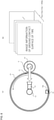
- the tire testing apparatus 1 includes a control computer 7 that performs a control thereof.
- the control computer 7 includes: a computing device 70 such as a CPU, which executes computing processing for a program; a storage device 71 such as a RAM and a hard disk, which stores information; a display device 73 such as a display, which displays information; an input device 72 such as a keyboard and a mouse, which is capable of inputting information; and a communication device 74 that transmits and receives a processing result of the computing device 70 and the information, which is stored in the storage device 71, via a network such as the Internet and a LAN.
- the display device 73 and the input device 72 may be composed integrally with each other.
- the touch panel display is often used, for example, for a portable communication terminal such as a tablet computer and a smartphone, but is not limited to this.
- the touch panel display is a device in which functions of the display device 73 and the input device 72 are integrated with each other in that an input can be directly performed on a display thereof by a predetermined input device (pen for a touch panel), a finger and the like.
- An arrangement relationship between the sensors 12a of the sensor installation portion 12, which are provided on the drum surface of the tire testing apparatus 1, and the transmission portion 11 is fixed.
- a radius of the drum 10 and a radius of the tire 5 do not coincide with each other. Accordingly, to control rotation speeds of the drum shaft 13 and the tire shaft 51 as mentioned above is present as one of methods for synchronizing the drum 10 and the tire 5 with each other.
- the rotation speeds themselves of the drum shaft 13 and the tire shaft 51 are not controlled, but such a method as follows is present. While rotating the drum shaft 13 and the tire shaft 51 at an arbitrary number of revolutions (number of revolutions may be fixed or variable), the measurement by the sensors 12a of the sensor installation portion 12 and the imaging of the ground contact surface of the tire 5 using the imaging device 14 are performed in advance.
- the angle ⁇ T of the tire shaft 51, the angle ⁇ D of the drum shaft 13 and the ground contact force measured by the sensors 12a at a point of measurement time and the angle ⁇ T of the tire shaft 51, the angle ⁇ D of the drum shaft 13 and the imaged image information at the point of measurement time are stored in association with each other.
- a ground contact force and image information regarding a ground contact surface of a certain tire 5 can also be obtained by being specified on the basis of an angle ⁇ T of a tire shaft 51 of the ground contact surface of the tire 5 taken as such a processing target and an angle ⁇ D of the drum shaft 13, which corresponds thereto.
- the drum shaft 13 and the tire shaft 51 are rotated for a predetermined time, whereby the image information of the ground contact surface of the tire 5 and the ground contact force of the tire 5 when 0 degree ⁇ ⁇ T ⁇ 360 degrees is established for the tire shaft 51 and 0 degree ⁇ ⁇ D ⁇ 360 degrees is established for the drum shaft 13 are individually acquired and measured in advance.
- FIG. 6 an example of a processing function in the control computer 7 is schematically illustrated in a block diagram.
- the computing device 70 of the control computer 7 includes a ground contact force measurement processing unit 700, a ground contact surface imaging processing unit 701, an edging processing unit 702, a division processing unit 703, a matching processing unit 704, a slip amount calculation processing unit 705, a wear energy calculation processing unit 706.
- a ground contact force measurement processing unit 700 a ground contact surface imaging processing unit 701
- edging processing unit 702 edging processing unit 702
- a division processing unit 703 edging processing unit
- 704 edging processing unit
- 703 edging processing unit
- 704 edging processing unit
- 703 edging processing unit
- 704 edging processing unit
- 703 edging processing unit
- a division processing unit 703 edging processing unit
- a matching processing unit 704 a slip amount calculation processing unit 705
- wear energy calculation processing unit 706 e.g., a wear energy calculation
- the ground contact force measurement processing unit 700 measures values of the sensors 12a, which are measured by the sensors 12a of the sensor installation portion 12 installed on the drum surface, the angle ⁇ T of the tire shaft 51 from the reference point at that time, and the angle ⁇ D of the drum shaft 13 from the reference point at that time.
- the measured values of the sensors 12a and the angle ⁇ T of the tire shaft 51 and the angle ⁇ D of the drum shaft 13 at that time and a time t are stored in the storage device 71 in association with one another.
- the imaging device 14 not only performs the imaging when the angle of the drum shaft 13 is ⁇ 1 , but also may always perform the imaging in advance, associate the angle ⁇ D of the drum shaft 13 and the angle ⁇ T of the tire shaft 51 at that time with each other, and extract image information when the angle of the drum shaft 13 is ⁇ 1 .
- the ground contact surface imaging processing unit 701 images a ground contact surface of an entire circumference (0 degree ⁇ ⁇ T ⁇ 360 degrees as the angle of the tire shaft 51) of the tire 5.
- the image information of the imaged tire surface is stored in the storage device 71 in association with the time t and the angle ⁇ T of the tire shaft 51.
- the edging processing unit 702 executes edging processing for detecting an edge of the image information imaged by the ground contact surface imaging processing unit 701.
- edge detection processing is processing for detecting an outline included in the image information, and includes a variety of known methods. For example, changes (gradients) of respective pixel values of the image information are calculated by differentiation and the like, whereby the edge can be detected.
- an outline (tread pattern) of the ground contact surface of the tire 5 will be detected.
- the division processing unit 703 divides image information on a certain ground contact surface (angle of a certain tire shaft 51), the image information being edged by the edging processing unit 702, into regions with a predetermined size. Then, when the number of bright spot pixels in each of the regions is a predetermined threshold value or more, the division processing unit 703 further divides the region. It is preferable that the division processing unit 703 divide the region into two; however, no limitations are imposed thereon. Note that the division processing unit 703 does not divide the region if the number of bright spot pixels in the region is less than the predetermined threshold value. The division processing unit 703 repeats the division of the regions until the number of bright spot pixels in the region becomes less than the predetermined threshold value.
- the division of the region which is based on the number of bright spot pixels, is performed for matching processing by a desired resolution. Accordingly, if the division of the region is such division processing that the desired resolution is obtained, then a determination may be made on the basis of a criterion other than the bright spot pixels, for example, a ratio of the bright spot pixels and pixels other than the same. Moreover, even in the case of using the number of bright spot pixels, the processing may be other than such a comparison between the number of pixels and the threshold value.
- the matching processing unit 704 adopts, as a template, one of the regions divided by the division processing unit 703, and acquires a center coordinate thereof. Moreover, the matching processing unit 704 performs matching processing for image information edged at different time and the region of the template with each other, specifies a corresponding region (for example, a region with highest similarity), and acquires a center coordinate thereof. The matching processing unit 704 executes the matching processing in a necessary region and an angle (ground contact surface of the tire 5) of the tire shaft 51.
- the wear energy calculation processing unit 706 associates the ground contact force measured by the ground contact force measurement processing unit 700 and the slip amount calculated by the slip amount calculation processing unit 705 with each other, and computes these, for example, multiplies these by each other, thereby calculating wear energy.
- the ground contact force measurement processing unit 700 measures the values of the sensors 12a, which are measured by the sensors 12a of the sensor installation portion 12 installed on the drum surface, the angle ⁇ T of the tire shaft 51 from the reference point at that time, and the angle ⁇ D of the drum shaft 13 from the reference point at that time, and allows storage of the measured values of the sensors 12a and the angles ⁇ T and ⁇ D in association with the time t.
- the ground contact surface imaging processing unit 701 images the tire 5, which is brought into ground contact with the transmission portion 11, via the transmission portion 11 installed on the drum surface, thereby acquiring the image information of the ground contact surface of the entire circumference or part of the tire 5 (S100).
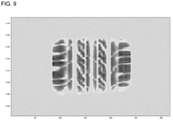
- the ground contact surface imaging processing unit 701 associates the angle ⁇ T of the tire shaft 51 and the angle ⁇ D of the drum shaft 13 at that time and the time t with the imaged image information, and causes the storage device 71 to store the image information. It is Figs. 8(a) and 8(b) that schematically illustrates this.
- Fig 8(a) is a view schematically illustrating a state of imaging the ground contact surface of the tire 5, and Fig.
- FIG. 8(b) is a view illustrating image information obtained thereby, the image information being regarding the ground contact surface of the tire 5 at every angle ⁇ T of the tire shaft 51. Moreover, an example of the image information of the ground contact surface of the tire 5 is illustrated in Fig. 9 .
- the edging processing unit 702 When the image information of the ground contact surface of the tire 5 is acquired as described above, the edging processing unit 702 performs gray-scale conversion for each of the image information, and performs the edging processing for the image information subjected to the gray-scale conversion (S110).
- the image information obtained by performing the gray-scale conversion for the image information of the ground contact surface of the tire 5 in Fig. 9 is illustrated in Fig. 10 .
- image information thus edged is illustrated in Fig. 11 .
- the division processing unit 703 divides the image information on the ground contact surface (angle of the tire shaft 51, which corresponds to the ground contact surface taken as a processing target) taken as a processing target, the image information having been edged by the edging processing unit 702, into regions with a predetermined size (S120). It is Fig. 12 that schematically illustrates this. Then, when the number of bright spot pixels in each of the regions satisfies a predetermined condition, for example, is a predetermined threshold value or more, the division processing unit 703 further divides the region, and repeats the division of the regions until the number of bright spot pixels in a region thus already divided becomes less than the predetermined threshold value (S130). It is Fig. 13 that schematically illustrates this.
- the matching processing unit 704 adopts one of such regions as a template, and acquires a center coordinate (X1, Y1) thereof (S140). It is Fig. 14 that schematically illustrates this.
- the matching processing unit 704 performs matching processing for image information edged at different time (time t+ ⁇ t) from the image information (image information at the time t) divided in S120, and the image in the region of the template with each other, specifies a corresponding region (for example, a region with highest similarity), and acquire a center coordinate (X2, Y2) thereof (S150).
- a range to be subjected to the matching processing only a peripheral fixed range of the region that composes the template (that is, a range composed of coordinates of the template in the image information edged at the time t) is recommended to be subjected to be the matching processing.
- Fig. 15 that schematically illustrates this. Then, the storage device 71 is caused to store a correspondence relationship between the center coordinate (X1, Y1) of the template and the center coordinate (X2, Y2).
- the above processing is executed for all the regions of the image information in the ground contact surface (angle of the tire shaft 51) of the tire 5, for which the slip amount is required to be calculated (S160, S170).
- the slip amount is calculated.
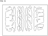
- the slip amount calculated as described above is displayed to be superimposed on the edged image information ( Fig. 11 ) at the time t.
- the slip amount is recommended to be displayed so as to be visually distinguishable from one another by arrows having lengths, thicknesses, colors or the like, each of which corresponds to the slip amount. It is Fig. 16 that schematically illustrates this.
- the wear energy calculation processing unit 706 extracts the ground contact force, which corresponds to the angle ⁇ T of the tire shaft 51, from the storage unit, computes these, and calculates wear energy.
- Such processing as described above is executed, whereby the region at the time of performing the matching processing for calculating the slip amount can be set automatically, and accordingly, a load applied to the matching processing can also be reduced.
- the range in which such image pattern matching for calculating the slip amount of the tire 5 can be set automatically and appropriately.
Landscapes
- Engineering & Computer Science (AREA)
- Physics & Mathematics (AREA)
- General Physics & Mathematics (AREA)
- Computer Vision & Pattern Recognition (AREA)
- Theoretical Computer Science (AREA)
- Quality & Reliability (AREA)
- Mechanical Engineering (AREA)
- Tires In General (AREA)
- Length Measuring Devices By Optical Means (AREA)
Claims (4)
- Reifentestgerät (1) vom Trommeltyp, umfassend:eine Trommel (10) mit einem Übertragungsabschnitt (11) an einer äußeren Umfangsflächeeine Abbildungsvorrichtung (14), die eine Bodenkontaktfläche eines Reifens (5) von einer Innenseite der Trommel (10) über den Übertragungsabschnitt (11) abbildet, wobei der Reifen (5) an einer Reifenwelle (51) befestigt ist;eine Bodenkontaktflächen-Abbildungsverarbeitungseinheit (701), die unter Verwendung der Abbildungsvorrichtung (14) die Bodenkontaktfläche abbildet, wenn der Reifen (5) in Bodenkontakt mit dem Übertragungsabschnitt (11) gebracht wird, wodurch Bildinformationen der Bodenkontaktfläche des gesamten Umfangs oder eines Teils des Reifens (5) erfasst werden, wobei die Bildinformationen die abgebildete Bodenkontaktfläche des Reifens in jedem Winkel θT der Reifenwelle (51) sind;eine Kantenverarbeitungseinheit (702), die eine Kantenverarbeitung der Bildinformationen der abgebildeten Bodenkontaktfläche des Reifens (5) durchführt;eine Teilungsverarbeitungseinheit (703), die eine Teilungsverarbeitung der Bildinformation, die der Kantenverarbeitung unterzogen wurde, in Bereiche durchführt, die eine vorbestimmte Auflösungsbedingung erfüllen;eine Anpassungsverarbeitungseinheit (704), die eine Anpassungsverarbeitung unter Verwendung der unterteilten Bereiche durchführt,wobei die Anpassungsverarbeitungseinheit (704) einen der durch die Teilungsverarbeitungseinheit (703) geteilten Bereiche als eine Schablone annimmt und eine Anpassungsverarbeitung zum Anpassen des Bereichs der Schablone und der Bildinformation der Bodenkontaktoberfläche des Reifens (5) aneinander durchführt, wobei die Bildinformation, die angepasst wird, der Kantenverarbeitung zu einer anderen Zeit als dem geteilten Bereich der Schablone unterzogen wird; undeine Schlupfbetragsberechnungs-Verarbeitungseinheit (705), die einen Schlupfbetrag unter Verwendung eines Ergebnisses der Anpassungsverarbeitung und eines durch einen Rotationsbetrag der Trommel (10) erzeugten Bodenkontaktflächen-Bewegungsbetrags berechnet,wobei der Bewegungsbetrag der Bodenkontaktfläche eine Differenzzeit multipliziert mit einer Geschwindigkeit der Trommel (10) darstellt.
- Reifentestgerät (1) nach Anspruch 1,
wobei die Teilungsverarbeitungseinheit (703):die Bildinformation, die der Kantenverarbeitung unterzogen wird, in Bereiche mit einer vorbestimmten Größe unterteilt; undin jedem der unterteilten Bereiche eine Verarbeitung zum Wiederholen der Unterteilung des Bereichs durchführt, bis eine Anzahl von hellen Fleckenpixeln in dem Bereich kleiner als ein vorbestimmter Schwellenwert wird. - Reifentestgerät (1) nach Anspruch 1 oder 2,
wobei die Schlupfbetragsberechnungs-Verarbeitungseinheit (705):eine Koordinate eines Punktes an einer vorbestimmten Position in dem geteilten Bereich und eine Koordinate eines entsprechenden Punktes in dem angepassten Bereich berechnet und dadurch eine Verschiebung berechnet; undBerechnen des Schlupfbetrags unter Verwendung der berechneten Verschiebung. - Computerprogramm, das Anweisungen enthält, die, wenn das Programm von einem Computer ausgeführt wird, den Computer veranlassen, wie folgt zu funktionieren:eine Bodenkontaktoberflächen-Abbildungsverarbeitungseinheit (701), die unter Verwendung einer Abbildungsvorrichtung (14) eine Bodenkontaktoberfläche abbildet, wenn ein Reifen (5) in Bodenkontakt mit einem Übertragungsabschnitt (11) einer Trommel (10) gebracht wird, wodurch Bildinformationen der Bodenkontaktoberfläche des gesamten Umfangs oder eines Teils des Reifens (5) erfasst werden,wobei die Bildinformation die abgebildete Bodenkontaktfläche des Reifens bei jedem Winkel θT einer Reifenwelle (51) ist;die Abbildungsvorrichtung (14) die Bodenkontaktfläche des Reifens (5) von der Innenseite der Trommel (10) über den Übertragungsabschnitt (11) abbildet, der an einer äußeren Umfangsfläche der Trommel (10) vorgesehen ist, wobei der Reifen (5) an der Reifenwelle (51) befestigt ist;eine Kantenverarbeitungseinheit (702), die eine Kantenverarbeitung der Bildinformation der abgebildeten Bodenkontaktfläche des Reifens (5) durchführt;eine Teilungsverarbeitungseinheit (703), die eine Teilungsverarbeitung der Bildinformation, die der Kantenverarbeitung unterzogen wurde, in Bereiche durchführt, die eine vorbestimmte Auflösungsbedingung erfüllen;eine Anpassungsverarbeitungseinheit (704), die eine Anpassungsverarbeitung unter Verwendung der unterteilten Bereiche durchführt,wobei die Anpassungsverarbeitungseinheit (704) einen der durch die Teilungsverarbeitungseinheit (703) geteilten Bereiche als eine Schablone annimmt und eine Anpassungsverarbeitung zum Anpassen des Bereichs der Schablone und der Bildinformation der Bodenkontaktfläche des Reifens (5) aneinander durchführt, wobei die Bildinformation, die angepasst wird, der Kantenverarbeitung zu einer anderen Zeit als der geteilte Bereich der Schablone unterzogen wird; und
eine Schlupfbetragsberechnungs-Verarbeitungseinheit (705), die einen Schlupfbetrag unter Verwendung eines Ergebnisses der Anpassungsverarbeitung und eines durch einen Rotationsbetrag der Trommel (10) erzeugten Bodenkontaktflächen-Bewegungsbetrags berechnet,wobei der Bewegungsbetrag der Bodenkontaktfläche eine Differenzzeit multipliziert mit einer Geschwindigkeit der Trommel (10) darstellt.
Applications Claiming Priority (2)
| Application Number | Priority Date | Filing Date | Title |
|---|---|---|---|
| JP2018176926A JP6467104B1 (ja) | 2018-09-21 | 2018-09-21 | タイヤ試験装置 |
| PCT/JP2019/034724 WO2020059490A1 (ja) | 2018-09-21 | 2019-09-04 | タイヤ試験装置 |
Publications (3)
| Publication Number | Publication Date |
|---|---|
| EP3686572A1 EP3686572A1 (de) | 2020-07-29 |
| EP3686572A4 EP3686572A4 (de) | 2021-01-20 |
| EP3686572B1 true EP3686572B1 (de) | 2022-03-16 |
Family
ID=65270623
Family Applications (1)
| Application Number | Title | Priority Date | Filing Date |
|---|---|---|---|
| EP19862009.8A Active EP3686572B1 (de) | 2018-09-21 | 2019-09-04 | Reifenprüfvorrichtung |
Country Status (6)
| Country | Link |
|---|---|
| US (2) | US20200400533A1 (de) |
| EP (1) | EP3686572B1 (de) |
| JP (1) | JP6467104B1 (de) |
| KR (1) | KR102101646B1 (de) |
| CN (1) | CN111247412B (de) |
| WO (1) | WO2020059490A1 (de) |
Families Citing this family (1)
| Publication number | Priority date | Publication date | Assignee | Title |
|---|---|---|---|---|
| WO2021145010A1 (ja) * | 2020-01-15 | 2021-07-22 | 日本国土開発株式会社 | 回転式破砕装置 |
Family Cites Families (21)
| Publication number | Priority date | Publication date | Assignee | Title |
|---|---|---|---|---|
| JPH0363504A (ja) * | 1989-08-01 | 1991-03-19 | Ohtsu Tire & Rubber Co Ltd :The | タイヤ形状撮影方法及び装置 |
| US5347588A (en) * | 1991-10-11 | 1994-09-13 | Bridgestone | Method and apparatus for video imaging of tire ground contact patch |
| US5357799A (en) * | 1992-07-14 | 1994-10-25 | Bridgestone Corporation | Method and apparatus for determining abrasion potential of tire treads |
| US5616839A (en) * | 1996-01-29 | 1997-04-01 | Ford Motor Company | Apparatus and method for measuring contact force distribution of a tire |
| JP4198610B2 (ja) | 2004-01-30 | 2008-12-17 | 株式会社ブリヂストン | タイヤ踏面の接地部測定装置、及びタイヤ踏面の接地部測定方法 |
| JP4150351B2 (ja) * | 2004-03-22 | 2008-09-17 | 株式会社ブリヂストン | タイヤ踏面の接地部測定方法 |
| JP2006133015A (ja) * | 2004-11-04 | 2006-05-25 | Yokohama Rubber Co Ltd:The | タイヤ接地形状測定方法及び装置 |
| JP2008256619A (ja) | 2007-04-06 | 2008-10-23 | Yokohama Rubber Co Ltd:The | タイヤ試験装置およびタイヤ試験方法 |
| KR20090046181A (ko) * | 2007-11-05 | 2009-05-11 | 한국타이어 주식회사 | 주행 타이어의 접지형상 측정장치 |
| JP5176517B2 (ja) | 2007-12-07 | 2013-04-03 | 横浜ゴム株式会社 | タイヤ踏面測定装置 |
| US7908917B2 (en) * | 2008-08-12 | 2011-03-22 | Kobe Steel, Ltd. | Driving control method of tire testing machine and tire testing machine |
| JP5243166B2 (ja) * | 2008-09-25 | 2013-07-24 | 株式会社ブリヂストン | タイヤ接地部の摩擦エネルギーの測定方法 |
| JP2011203207A (ja) * | 2010-03-26 | 2011-10-13 | Bridgestone Corp | タイヤの接地特性の測定方法及び測定装置 |
| JP5533216B2 (ja) | 2010-05-10 | 2014-06-25 | 横浜ゴム株式会社 | タイヤ性能測定システム及びタイヤ性能測定方法 |
| CN101886983A (zh) * | 2010-06-10 | 2010-11-17 | 沈阳理工大学 | 一种轮胎运动特性仿真系统 |
| KR101311868B1 (ko) * | 2011-11-17 | 2013-09-27 | 한국타이어 주식회사 | 타이어의 동적 접지압과 접지형상 측정장치 |
| JP6386304B2 (ja) | 2014-08-29 | 2018-09-05 | 東洋ゴム工業株式会社 | タイヤ踏面の接地面挙動測定装置、及びタイヤ踏面の接地面挙動測定方法 |
| JP6544018B2 (ja) | 2015-04-21 | 2019-07-17 | 横浜ゴム株式会社 | タイヤ解析装置及びタイヤ解析方法 |
| JP6514620B2 (ja) | 2015-10-01 | 2019-05-15 | Toyo Tire株式会社 | タイヤ接地面測定方法 |
| CN206496732U (zh) * | 2016-12-24 | 2017-09-15 | 安徽佳通乘用子午线轮胎有限公司 | 一种滚动轮胎胎面滑移测量系统 |
| CN108225798B (zh) * | 2017-12-26 | 2020-04-24 | 东南大学 | 基于边缘增强识别的轮胎滑移量测试系统及测试方法 |
-
2018
- 2018-09-21 JP JP2018176926A patent/JP6467104B1/ja active Active
-
2019
- 2019-09-04 CN CN201980005210.0A patent/CN111247412B/zh active Active
- 2019-09-04 US US16/648,161 patent/US20200400533A1/en not_active Abandoned
- 2019-09-04 WO PCT/JP2019/034724 patent/WO2020059490A1/ja not_active Ceased
- 2019-09-04 EP EP19862009.8A patent/EP3686572B1/de active Active
- 2019-09-04 KR KR1020207005422A patent/KR102101646B1/ko active Active
-
2021
- 2021-06-14 US US17/346,601 patent/US20210302273A1/en not_active Abandoned
Also Published As
| Publication number | Publication date |
|---|---|
| KR102101646B1 (ko) | 2020-04-17 |
| CN111247412B (zh) | 2021-10-29 |
| EP3686572A4 (de) | 2021-01-20 |
| US20200400533A1 (en) | 2020-12-24 |
| EP3686572A1 (de) | 2020-07-29 |
| US20210302273A1 (en) | 2021-09-30 |
| WO2020059490A1 (ja) | 2020-03-26 |
| CN111247412A (zh) | 2020-06-05 |
| KR20200035084A (ko) | 2020-04-01 |
| JP6467104B1 (ja) | 2019-02-06 |
| JP2020046383A (ja) | 2020-03-26 |
Similar Documents
| Publication | Publication Date | Title |
|---|---|---|
| US7377181B2 (en) | In-situ large area optical strain measurement using an encoded dot pattern | |
| CN105934310B (zh) | 刀具形状测定装置以及刀具形状测定方法 | |
| US20190128665A1 (en) | Method for the three dimensional measurement of a moving objects during a known movement | |
| EP3026632A2 (de) | Verbesserungen an oder im zusammenhang mit digitalen bildkorrelationssystemen | |
| EP2700903A1 (de) | Vorrichtung zur messung einer reifenoberflächenform und verfahren zur messung einer reifenoberflächenform | |
| US20170372466A1 (en) | Information processing apparatus and method of selecting viewpoint for measuring object, and measuring system | |
| EP3431920A1 (de) | Vorrichtung, system und verfahren zur überprüfung der kurbelwellenform | |
| EP3855154B1 (de) | Reifenprüfvorrichtung | |
| CN104802513B (zh) | 3d数字样张 | |
| EP3473996A1 (de) | System und verfahren zur berechnung des reibungskoeffizients des reifenkontakts | |
| KR100499764B1 (ko) | 디지털 이미지에서 객체를 측정하는 방법 및 시스템 | |
| CN107810384B (zh) | 条纹投影方法、条纹投影装置和计算机程序产品 | |
| EP3686572B1 (de) | Reifenprüfvorrichtung | |
| EP3861284A1 (de) | Optischer oberflächencodierer | |
| CN114323591B (zh) | 一种基于数字图像相关法的光畸变测量方法及测试系统 | |
| CN115049744A (zh) | 机器人手眼坐标转换方法、装置、计算机设备和存储介质 | |
| EP3193158B1 (de) | System und verfahren zur beurteilung des visuellen erscheinungsbildes einer reflektierenden oberfläche | |
| US11555751B2 (en) | Noncontact optical torque measurement of rotating component | |
| CN112991376B (zh) | 红外图像中的设备轮廓标注方法及系统 | |
| JP7516832B2 (ja) | タイヤの測定方法及びタイヤの表示方法 | |
| JP3384617B2 (ja) | 物体計測装置及びその方法 | |
| KR20250129664A (ko) | 로봇 표면 개질 시스템들 및 방법들 | |
| JP2010181270A (ja) | タイヤ状態推定方法、タイヤ状態推定装置、及びタイヤ状態推定プログラム | |
| JP2018534593A (ja) | 力測定によって物体の表面における圧力の作用を検出するためのシステム及び方法 | |
| JP2016061699A (ja) | タイヤ状態評価システムおよびタイヤ状態評価方法 |
Legal Events
| Date | Code | Title | Description |
|---|---|---|---|
| STAA | Information on the status of an ep patent application or granted ep patent |
Free format text: STATUS: THE INTERNATIONAL PUBLICATION HAS BEEN MADE |
|
| PUAI | Public reference made under article 153(3) epc to a published international application that has entered the european phase |
Free format text: ORIGINAL CODE: 0009012 |
|
| STAA | Information on the status of an ep patent application or granted ep patent |
Free format text: STATUS: THE APPLICATION HAS BEEN PUBLISHED |
|
| AK | Designated contracting states |
Kind code of ref document: A1 Designated state(s): AL AT BE BG CH CY CZ DE DK EE ES FI FR GB GR HR HU IE IS IT LI LT LU LV MC MK MT NL NO PL PT RO RS SE SI SK SM TR |
|
| AX | Request for extension of the european patent |
Extension state: BA ME |
|
| STAA | Information on the status of an ep patent application or granted ep patent |
Free format text: STATUS: REQUEST FOR EXAMINATION WAS MADE |
|
| 17P | Request for examination filed |
Effective date: 20200928 |
|
| RBV | Designated contracting states (corrected) |
Designated state(s): AL AT BE BG CH CY CZ DE DK EE ES FI FR GB GR HR HU IE IS IT LI LT LU LV MC MK MT NL NO PL PT RO RS SE SI SK SM TR |
|
| A4 | Supplementary search report drawn up and despatched |
Effective date: 20201221 |
|
| RIC1 | Information provided on ipc code assigned before grant |
Ipc: G01M 17/02 20060101AFI20201215BHEP Ipc: G06T 7/10 20170101ALI20201215BHEP Ipc: G01B 11/24 20060101ALI20201215BHEP Ipc: B60C 19/00 20060101ALI20201215BHEP |
|
| GRAP | Despatch of communication of intention to grant a patent |
Free format text: ORIGINAL CODE: EPIDOSNIGR1 |
|
| STAA | Information on the status of an ep patent application or granted ep patent |
Free format text: STATUS: GRANT OF PATENT IS INTENDED |
|
| RIC1 | Information provided on ipc code assigned before grant |
Ipc: B60C 11/03 20060101ALI20210917BHEP Ipc: G06T 7/12 20170101ALI20210917BHEP Ipc: G06T 7/00 20170101ALI20210917BHEP Ipc: B60C 99/00 20060101ALI20210917BHEP Ipc: G01M 17/02 20060101AFI20210917BHEP |
|
| DAV | Request for validation of the european patent (deleted) | ||
| DAX | Request for extension of the european patent (deleted) | ||
| INTG | Intention to grant announced |
Effective date: 20211015 |
|
| GRAS | Grant fee paid |
Free format text: ORIGINAL CODE: EPIDOSNIGR3 |
|
| GRAA | (expected) grant |
Free format text: ORIGINAL CODE: 0009210 |
|
| STAA | Information on the status of an ep patent application or granted ep patent |
Free format text: STATUS: THE PATENT HAS BEEN GRANTED |
|
| AK | Designated contracting states |
Kind code of ref document: B1 Designated state(s): AL AT BE BG CH CY CZ DE DK EE ES FI FR GB GR HR HU IE IS IT LI LT LU LV MC MK MT NL NO PL PT RO RS SE SI SK SM TR |
|
| REG | Reference to a national code |
Ref country code: GB Ref legal event code: FG4D |
|
| REG | Reference to a national code |
Ref country code: CH Ref legal event code: EP |
|
| REG | Reference to a national code |
Ref country code: DE Ref legal event code: R096 Ref document number: 602019012681 Country of ref document: DE |
|
| REG | Reference to a national code |
Ref country code: IE Ref legal event code: FG4D |
|
| REG | Reference to a national code |
Ref country code: AT Ref legal event code: REF Ref document number: 1476228 Country of ref document: AT Kind code of ref document: T Effective date: 20220415 |
|
| REG | Reference to a national code |
Ref country code: LT Ref legal event code: MG9D |
|
| REG | Reference to a national code |
Ref country code: NL Ref legal event code: MP Effective date: 20220316 |
|
| PG25 | Lapsed in a contracting state [announced via postgrant information from national office to epo] |
Ref country code: SE Free format text: LAPSE BECAUSE OF FAILURE TO SUBMIT A TRANSLATION OF THE DESCRIPTION OR TO PAY THE FEE WITHIN THE PRESCRIBED TIME-LIMIT Effective date: 20220316 Ref country code: RS Free format text: LAPSE BECAUSE OF FAILURE TO SUBMIT A TRANSLATION OF THE DESCRIPTION OR TO PAY THE FEE WITHIN THE PRESCRIBED TIME-LIMIT Effective date: 20220316 Ref country code: NO Free format text: LAPSE BECAUSE OF FAILURE TO SUBMIT A TRANSLATION OF THE DESCRIPTION OR TO PAY THE FEE WITHIN THE PRESCRIBED TIME-LIMIT Effective date: 20220616 Ref country code: LT Free format text: LAPSE BECAUSE OF FAILURE TO SUBMIT A TRANSLATION OF THE DESCRIPTION OR TO PAY THE FEE WITHIN THE PRESCRIBED TIME-LIMIT Effective date: 20220316 Ref country code: HR Free format text: LAPSE BECAUSE OF FAILURE TO SUBMIT A TRANSLATION OF THE DESCRIPTION OR TO PAY THE FEE WITHIN THE PRESCRIBED TIME-LIMIT Effective date: 20220316 Ref country code: BG Free format text: LAPSE BECAUSE OF FAILURE TO SUBMIT A TRANSLATION OF THE DESCRIPTION OR TO PAY THE FEE WITHIN THE PRESCRIBED TIME-LIMIT Effective date: 20220616 |
|
| REG | Reference to a national code |
Ref country code: AT Ref legal event code: MK05 Ref document number: 1476228 Country of ref document: AT Kind code of ref document: T Effective date: 20220316 |
|
| PG25 | Lapsed in a contracting state [announced via postgrant information from national office to epo] |
Ref country code: LV Free format text: LAPSE BECAUSE OF FAILURE TO SUBMIT A TRANSLATION OF THE DESCRIPTION OR TO PAY THE FEE WITHIN THE PRESCRIBED TIME-LIMIT Effective date: 20220316 Ref country code: GR Free format text: LAPSE BECAUSE OF FAILURE TO SUBMIT A TRANSLATION OF THE DESCRIPTION OR TO PAY THE FEE WITHIN THE PRESCRIBED TIME-LIMIT Effective date: 20220617 Ref country code: FI Free format text: LAPSE BECAUSE OF FAILURE TO SUBMIT A TRANSLATION OF THE DESCRIPTION OR TO PAY THE FEE WITHIN THE PRESCRIBED TIME-LIMIT Effective date: 20220316 |
|
| PG25 | Lapsed in a contracting state [announced via postgrant information from national office to epo] |
Ref country code: NL Free format text: LAPSE BECAUSE OF FAILURE TO SUBMIT A TRANSLATION OF THE DESCRIPTION OR TO PAY THE FEE WITHIN THE PRESCRIBED TIME-LIMIT Effective date: 20220316 |
|
| PG25 | Lapsed in a contracting state [announced via postgrant information from national office to epo] |
Ref country code: SM Free format text: LAPSE BECAUSE OF FAILURE TO SUBMIT A TRANSLATION OF THE DESCRIPTION OR TO PAY THE FEE WITHIN THE PRESCRIBED TIME-LIMIT Effective date: 20220316 Ref country code: SK Free format text: LAPSE BECAUSE OF FAILURE TO SUBMIT A TRANSLATION OF THE DESCRIPTION OR TO PAY THE FEE WITHIN THE PRESCRIBED TIME-LIMIT Effective date: 20220316 Ref country code: RO Free format text: LAPSE BECAUSE OF FAILURE TO SUBMIT A TRANSLATION OF THE DESCRIPTION OR TO PAY THE FEE WITHIN THE PRESCRIBED TIME-LIMIT Effective date: 20220316 Ref country code: PT Free format text: LAPSE BECAUSE OF FAILURE TO SUBMIT A TRANSLATION OF THE DESCRIPTION OR TO PAY THE FEE WITHIN THE PRESCRIBED TIME-LIMIT Effective date: 20220718 Ref country code: ES Free format text: LAPSE BECAUSE OF FAILURE TO SUBMIT A TRANSLATION OF THE DESCRIPTION OR TO PAY THE FEE WITHIN THE PRESCRIBED TIME-LIMIT Effective date: 20220316 Ref country code: EE Free format text: LAPSE BECAUSE OF FAILURE TO SUBMIT A TRANSLATION OF THE DESCRIPTION OR TO PAY THE FEE WITHIN THE PRESCRIBED TIME-LIMIT Effective date: 20220316 Ref country code: CZ Free format text: LAPSE BECAUSE OF FAILURE TO SUBMIT A TRANSLATION OF THE DESCRIPTION OR TO PAY THE FEE WITHIN THE PRESCRIBED TIME-LIMIT Effective date: 20220316 Ref country code: AT Free format text: LAPSE BECAUSE OF FAILURE TO SUBMIT A TRANSLATION OF THE DESCRIPTION OR TO PAY THE FEE WITHIN THE PRESCRIBED TIME-LIMIT Effective date: 20220316 |
|
| PG25 | Lapsed in a contracting state [announced via postgrant information from national office to epo] |
Ref country code: PL Free format text: LAPSE BECAUSE OF FAILURE TO SUBMIT A TRANSLATION OF THE DESCRIPTION OR TO PAY THE FEE WITHIN THE PRESCRIBED TIME-LIMIT Effective date: 20220316 Ref country code: IS Free format text: LAPSE BECAUSE OF FAILURE TO SUBMIT A TRANSLATION OF THE DESCRIPTION OR TO PAY THE FEE WITHIN THE PRESCRIBED TIME-LIMIT Effective date: 20220716 Ref country code: AL Free format text: LAPSE BECAUSE OF FAILURE TO SUBMIT A TRANSLATION OF THE DESCRIPTION OR TO PAY THE FEE WITHIN THE PRESCRIBED TIME-LIMIT Effective date: 20220316 |
|
| REG | Reference to a national code |
Ref country code: DE Ref legal event code: R097 Ref document number: 602019012681 Country of ref document: DE |
|
| PLBE | No opposition filed within time limit |
Free format text: ORIGINAL CODE: 0009261 |
|
| STAA | Information on the status of an ep patent application or granted ep patent |
Free format text: STATUS: NO OPPOSITION FILED WITHIN TIME LIMIT |
|
| PG25 | Lapsed in a contracting state [announced via postgrant information from national office to epo] |
Ref country code: DK Free format text: LAPSE BECAUSE OF FAILURE TO SUBMIT A TRANSLATION OF THE DESCRIPTION OR TO PAY THE FEE WITHIN THE PRESCRIBED TIME-LIMIT Effective date: 20220316 |
|
| 26N | No opposition filed |
Effective date: 20221219 |
|
| PG25 | Lapsed in a contracting state [announced via postgrant information from national office to epo] |
Ref country code: SI Free format text: LAPSE BECAUSE OF FAILURE TO SUBMIT A TRANSLATION OF THE DESCRIPTION OR TO PAY THE FEE WITHIN THE PRESCRIBED TIME-LIMIT Effective date: 20220316 |
|
| PG25 | Lapsed in a contracting state [announced via postgrant information from national office to epo] |
Ref country code: MC Free format text: LAPSE BECAUSE OF FAILURE TO SUBMIT A TRANSLATION OF THE DESCRIPTION OR TO PAY THE FEE WITHIN THE PRESCRIBED TIME-LIMIT Effective date: 20220316 |
|
| REG | Reference to a national code |
Ref country code: CH Ref legal event code: PL |
|
| REG | Reference to a national code |
Ref country code: BE Ref legal event code: MM Effective date: 20220930 |
|
| PG25 | Lapsed in a contracting state [announced via postgrant information from national office to epo] |
Ref country code: LU Free format text: LAPSE BECAUSE OF NON-PAYMENT OF DUE FEES Effective date: 20220904 |
|
| PG25 | Lapsed in a contracting state [announced via postgrant information from national office to epo] |
Ref country code: LI Free format text: LAPSE BECAUSE OF NON-PAYMENT OF DUE FEES Effective date: 20220930 Ref country code: IT Free format text: LAPSE BECAUSE OF FAILURE TO SUBMIT A TRANSLATION OF THE DESCRIPTION OR TO PAY THE FEE WITHIN THE PRESCRIBED TIME-LIMIT Effective date: 20220316 Ref country code: IE Free format text: LAPSE BECAUSE OF NON-PAYMENT OF DUE FEES Effective date: 20220904 Ref country code: CH Free format text: LAPSE BECAUSE OF NON-PAYMENT OF DUE FEES Effective date: 20220930 |
|
| PG25 | Lapsed in a contracting state [announced via postgrant information from national office to epo] |
Ref country code: BE Free format text: LAPSE BECAUSE OF NON-PAYMENT OF DUE FEES Effective date: 20220930 |
|
| PG25 | Lapsed in a contracting state [announced via postgrant information from national office to epo] |
Ref country code: CY Free format text: LAPSE BECAUSE OF FAILURE TO SUBMIT A TRANSLATION OF THE DESCRIPTION OR TO PAY THE FEE WITHIN THE PRESCRIBED TIME-LIMIT Effective date: 20220316 |
|
| GBPC | Gb: european patent ceased through non-payment of renewal fee |
Effective date: 20230904 |
|
| PG25 | Lapsed in a contracting state [announced via postgrant information from national office to epo] |
Ref country code: MK Free format text: LAPSE BECAUSE OF FAILURE TO SUBMIT A TRANSLATION OF THE DESCRIPTION OR TO PAY THE FEE WITHIN THE PRESCRIBED TIME-LIMIT Effective date: 20220316 Ref country code: HU Free format text: LAPSE BECAUSE OF FAILURE TO SUBMIT A TRANSLATION OF THE DESCRIPTION OR TO PAY THE FEE WITHIN THE PRESCRIBED TIME-LIMIT; INVALID AB INITIO Effective date: 20190904 |
|
| PG25 | Lapsed in a contracting state [announced via postgrant information from national office to epo] |
Ref country code: GB Free format text: LAPSE BECAUSE OF NON-PAYMENT OF DUE FEES Effective date: 20230904 |
|
| PG25 | Lapsed in a contracting state [announced via postgrant information from national office to epo] |
Ref country code: GB Free format text: LAPSE BECAUSE OF NON-PAYMENT OF DUE FEES Effective date: 20230904 |
|
| PG25 | Lapsed in a contracting state [announced via postgrant information from national office to epo] |
Ref country code: MT Free format text: LAPSE BECAUSE OF FAILURE TO SUBMIT A TRANSLATION OF THE DESCRIPTION OR TO PAY THE FEE WITHIN THE PRESCRIBED TIME-LIMIT Effective date: 20220316 |
|
| PGFP | Annual fee paid to national office [announced via postgrant information from national office to epo] |
Ref country code: FR Payment date: 20250922 Year of fee payment: 7 |
|
| PG25 | Lapsed in a contracting state [announced via postgrant information from national office to epo] |
Ref country code: TR Free format text: LAPSE BECAUSE OF FAILURE TO SUBMIT A TRANSLATION OF THE DESCRIPTION OR TO PAY THE FEE WITHIN THE PRESCRIBED TIME-LIMIT Effective date: 20220316 |
|
| PGFP | Annual fee paid to national office [announced via postgrant information from national office to epo] |
Ref country code: DE Payment date: 20250930 Year of fee payment: 7 |