EP3686873B1 - Unité d'affichage à del - Google Patents
Unité d'affichage à del Download PDFInfo
- Publication number
- EP3686873B1 EP3686873B1 EP18923760.5A EP18923760A EP3686873B1 EP 3686873 B1 EP3686873 B1 EP 3686873B1 EP 18923760 A EP18923760 A EP 18923760A EP 3686873 B1 EP3686873 B1 EP 3686873B1
- Authority
- EP
- European Patent Office
- Prior art keywords
- rear body
- led display
- display unit
- lamp plate
- hole
- Prior art date
- Legal status (The legal status is an assumption and is not a legal conclusion. Google has not performed a legal analysis and makes no representation as to the accuracy of the status listed.)
- Active
Links
Images


Classifications
-
- G—PHYSICS
- G09—EDUCATION; CRYPTOGRAPHY; DISPLAY; ADVERTISING; SEALS
- G09F—DISPLAYING; ADVERTISING; SIGNS; LABELS OR NAME-PLATES; SEALS
- G09F9/00—Indicating arrangements for variable information in which the information is built-up on a support by selection or combination of individual elements
- G09F9/30—Indicating arrangements for variable information in which the information is built-up on a support by selection or combination of individual elements in which the desired character or characters are formed by combining individual elements
- G09F9/301—Indicating arrangements for variable information in which the information is built-up on a support by selection or combination of individual elements in which the desired character or characters are formed by combining individual elements flexible foldable or roll-able electronic displays, e.g. thin LCD, OLED
-
- H—ELECTRICITY
- H10—SEMICONDUCTOR DEVICES; ELECTRIC SOLID-STATE DEVICES NOT OTHERWISE PROVIDED FOR
- H10W—GENERIC PACKAGES, INTERCONNECTIONS, CONNECTORS OR OTHER CONSTRUCTIONAL DETAILS OF DEVICES COVERED BY CLASS H10
- H10W90/00—Package configurations
-
- G—PHYSICS
- G09—EDUCATION; CRYPTOGRAPHY; DISPLAY; ADVERTISING; SEALS
- G09F—DISPLAYING; ADVERTISING; SIGNS; LABELS OR NAME-PLATES; SEALS
- G09F9/00—Indicating arrangements for variable information in which the information is built-up on a support by selection or combination of individual elements
- G09F9/30—Indicating arrangements for variable information in which the information is built-up on a support by selection or combination of individual elements in which the desired character or characters are formed by combining individual elements
- G09F9/33—Indicating arrangements for variable information in which the information is built-up on a support by selection or combination of individual elements in which the desired character or characters are formed by combining individual elements being semiconductor devices, e.g. diodes
-
- H—ELECTRICITY
- H10—SEMICONDUCTOR DEVICES; ELECTRIC SOLID-STATE DEVICES NOT OTHERWISE PROVIDED FOR
- H10W—GENERIC PACKAGES, INTERCONNECTIONS, CONNECTORS OR OTHER CONSTRUCTIONAL DETAILS OF DEVICES COVERED BY CLASS H10
- H10W78/00—Detachable holders for supporting packaged chips in operation
Definitions
- the application belongs to the technical field of LED display screens, in particular to an LED display unit.
- LED display screen has the advantages of high brightness, low working voltage, low power consumption, large size, long service life, impact resistance and stable performance, and is widely used in people's production and life.
- the development prospect of LED display screen is extremely broad, and it is developing towards higher brightness, higher weather resistance, higher luminous density, higher luminance uniformity, higher reliability and full color.
- LED display screens are widely used in sports venues, commercial applications, banks, securities, postal services, docks, shopping malls, railway stations, telecommunications, agencies, monitoring, schools, restaurants, hotels, entertainment, and other outdoor places for advertising.
- LED display screen such as outdoor advertisement, large scene display, LED display tiles or large screen game interfaces.
- Large screen displays are usually spliced by a plurality of display devices through light boxes to form large screens or super large screens.
- the whole screen of the LED large-screen display is spliced by a plurality of LED boxes.
- traction and hoisting equipment are needed to complete the splicing.
- construction personnels need to perform complicated wiring, power connection and line connection work behind the display screen. The overall process is complex and prone to errors.
- spliced LED large-screen displays usually focus on seamless splicing, the convenience and stability of splicing and installation.
- the existing spliced LED large-screen displays are basically planar, there are few large curved screens.
- the few large curved screens usually realize curved surface effects by setting splicing angles of LED lamp boxes with multiple planes. This curved surface effect is not a real curved surface.
- Their LED light boxes still adopt the traditional box structure and do not actually realize curved surface design.
- CN203799594U provides a bendable LED display screen, in which two adjacent LED display modules are connected by a soft connecting piece to realize bending.
- CN107833523A discloses a flexible LED display screen, in which a plurality of bottom housing strips are sequentially arranged into a bottom housing panel assembly, and they are connected through flexible connecting parts, so that adjacent bottom housing strips could be bent.
- US2016/212864A1 proposes an image display device having a flexible display unit which is transformable in shape.
- US9671530B2 teaches an optical member supporter and curved display device including the same, focusing on how to maintain the luminance uniformity of curved screens.
- the existing LED display screen adopts a traditional planar LED display unit structure, can only realize curved LED display screen by adjusting the splicing angle of each LED display unit, and does not actually realize curved design.
- an LED display unit capable of realizing any curved surface is provided.
- the above LED display unit of the present application further comprises an elastic stop piece for limiting the ultimate bending degree of the lamp plate, wherein the elastic stop piece is positioned between the lamp plate and the rear body.
- the elastic stop piece is set as a strip-shaped elastic piece; each of the rear body unit is equally spaced on the elastic stop piece.
- the side of the lamp plate facing away from the LED lamps is provided with positioning posts, correspondingly, the rear body unit is provided with positioning holes; the lamp plate and the rear body are fixedly connected through the matching of the positioning posts and positioning holes, or fasteners, the positioning holes and the positioning posts are matched to fixedly connect the lamp plate and the rear body.
- the centers of the positioning posts are provided with internal threaded holes
- the fasteners are connection screws
- the connection screws pass through the positioning holes and are matched with the internal threaded holes to fixedly connect the lamp plate and the rear body.
- the positioning holes are stepped holes, the threaded portion of the connection screw is matched with the small end of the stepped hole, and the head of the connection screw is positioned in the stepped hole.
- the outer surfaces of the positioning posts are provided with external threads, the fasteners are nuts, the positioning posts pass through the positioning holes and are matched with the nuts to fixedly connect the lamp plate and the rear body.
- the positioning holes are stepped holes, the threaded portion of the positioning post is matched with the small end of the stepped hole, and the nut is positioned in the stepped hole.
- the positioning post is set to be multiple and distributed in rows.
- the positioning post is a cylinder, the end close to the lamp plate is a front end, and the other end is a rear end; the diameter of the front end is larger than the diameter of the rear end; the elastic stop piece is provided with a plurality of first through holes corresponding to the rear ends, and the elastic stop piece is sleeved on the rear end through the first through hole.
- the length of the first through hole is greater than the length of the rear end; when the LED display unit is bent, the positioning post slides along the first through hole.
- the elastic stop piece is provided with a second through hole, and the stop block of the rear body is inserted into the second through hole; when the LED display unit is bent, the stop block slides along the second through hole, and when the stop block abuts the end of the second through hole in the sliding direction of the positioning post, the positioning post abuts against the end of the first through hole in the sliding direction of the positioning post, or the positioning post does not abut against the end of the first through hole in the sliding direction of the positioning post.
- the rear body unit C is provided with a third through hole
- the lamp plate is correspondingly provided with a connector for connecting a power box, and the connector is inserted into the third through hole.
- the side of the rear body unit connected to the other rear body unit is set as an inclined plane, and the inclined plane is inclined from one end of the rear body unit near the lamp plate to one end of the rear body unit facing away from the lamp plate.
- the LED display unit provided by the application has the beneficial effects that compared with the prior art, the LED display unit of the application adopts a flexible lamp plate, can directly adjust a single LED display unit to form a curved surface, can also arbitrarily adjust the curved surface shape, and the curved surface shape formed by a plurality of LED display units is more closely attached, and even can be assembled into a special-shaped curved surface; A plurality of rear body units are fixed on the lamp plate, and gaps exist between rearbody units, which is beneficial to releasing bending stress and preventing rearbody from breaking during bending.
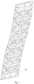
- an LED display unit provided by an embodiment of the present application includes a front body 1, a lamp plate 2 and a rear body 3, wherein the lamp plate 2 is bendable and flexible, the rear body 3 comprises a plurality of rear body units 31, the front body 1 is covered on one side of the lamp plate 2 provided with LED lamps, each of the rear body units 31 is fixedly connected to a side of the lamp plate 2 facing away from the LED lamps, and adjacent rear body units 31 are arranged at intervals.
- a bendable and flexible lamp plate is adopted, so that every single LED display unit can be directly adjusted into a curved surface and can be adjusted into any curved surface shape, and the curved surface shape formed by a plurality of LED display units is more closely attached, and even can be assembled into special-shaped curved surfaces; a plurality of rear body units 31 are fixed on the lamp plate 2, and gaps exist between the rear body units 31, which is beneficial to releasing bending stress and preventing the rear body 3 from breaking during bending.
- the lamp plate 2 comprises a PCB board, LED lamps and electronic components, wherein the LED lamps are positioned on one side of the PCB board, and the electronic components are welded on the side of the PCB board facing away from the LED lamps.
- the front body 1 is a mesh mask, which can protect LED lamps and prolong the service life of the lamp plate 2.
- it further includes an elastic stop piece 4 for limiting the ultimate bending degree of the lamp plate 2, and the elastic stop piece 4 is positioned between the lamp plate 2 and the rear body 3; Limiting the ultimate bending degree of the LED display unit can prevent the LED display unit from being damaged due to excessive bending and prolong the service life of the LED display unit.
- the elastic stop piece 4 is set as a strip-shaped elastic piece; Material can be saved, and the ultimate bending degree of the LED display unit can be increased to adjust more curved surface shapes.
- each rear body unit 31 is equally spaced on the elastic stop piece 4; so that the stress is uniform everywhere and the service life of the LED display unit is prolonged.
- the side of the lamp plate 2 facing away from the LED lamps is provided with positioning posts 21, correspondingly, the rear body unit 31 is provided with positioning holes 311;the lamp plate 2 and the rear body 3 are fixedly connected through the matching of the positioning posts 21 and positioning holes 311; the positioning posts 21 and positioning holes 311 form an interference fit, the connecting structure is simple, and is convenient for disassembly, assembly and maintenance.
- the side of the lamp plate 2 facing away from the LED lamps is provided with positioning posts 21, correspondingly, the rear body unit 31 is provided with positioning holes 311; fasteners, the positioning holes 311 and the positioning posts 21 are matched to fixedly connect the lamp plate 2 and the rear body 3.
- the connection is more solid and reliable, is not easy to fall apart, and is convenient for disassembly, assembly and maintenance.
- the centers of the positioning posts 21 are provided with internal threaded holes 211, the fasteners are connection screws 5, the connection screws 5 pass through the positioning holes 311 and are matched with the internal threaded holes 211 to fixedly connect the lamp plate 2 and the rear body 3.
- the connecting structure is simple and convenient for processing and maintenance.
- the positioning holes 311 are stepped holes, the threaded portion of the connection screw 5 is matched with the small end of the stepped hole, and the head of the connection screw 5 is positioned in the stepped hole. It can prevent the connection screw 5 from protruding out of the rear body 3, causing wear and loosening. At the same time, it can play a waterproof role.
- the outer surfaces of the positioning posts 21 are provided with external threads, the fasteners are nuts, the positioning posts 21 pass through the positioning holes 311 and are matched with the nuts to fixedly connect the lamp plate 2 and the rear body 3.
- the connecting structure is simple and convenient for processing and maintenance.
- the positioning holes 311 are stepped holes, the threaded portion of the positioning post 21 is matched with the small end of the stepped hole, and the nut is positioned in the stepped hole. It can prevent the nut from protruding out of the rear body 3, causing wear and loosening. At the same time, it can play a waterproof role.
- the positioning post is set to be multiple and distributed in rows.
- the layout of lamp plate 2 is reasonably planned to facilitate processing and installation.
- the plurality of positioning posts 21 are distributed in five rows, two elastic stop pieces 4 are provided, and the two elastic stop pieces 4 are respectively sleeved on the second row and the fourth row of positioning posts 21;
- the ultimate bending degree of the LED display unit can be well limited.
- the positioning post is a cylinder 21, the end close to the lamp plate is a front end 212, and the other end is a rear end 213; the diameter of the front end 212 is larger than the diameter of the rear end 213; the elastic stop piece 4 is provided with a plurality of first through holes 41 corresponding to the rear ends 213, and the elastic stop piece 4 is sleeved on the rear end 213 through the first through hole 41.
- the elastic stop piece 4 could be fasten more firmly.
- the length of the first through hole 41 is greater than the left and right lengths of the rear end 213; when the LED display unit is bent, the positioning post 21 slides along the first through hole 41. When the positioning post 21 moves to the leftmost or rightmost end of the first through hole 41, the positioning post 21 cannot continue to move to the left or right. At this time, the bending of the LED display unit is at ultimate bending degree to prevent the LED display unit from excessively bending.
- the elastic stop piece 4 is provided with a second through hole 42, and the stop block 32 of the rear body 3 is inserted into the second through hole 42; when the LED display unit is bent, the stop block 32 slides along the second through hole 42, and when the stop block 32 abuts the end of the second through hole 42 in the sliding direction of the positioning post 21, the positioning post 21 abuts against the end of the first through hole 41 in the sliding direction of the positioning post 21, or the positioning post 21 does not abut against the end of the first through hole 41 in the sliding direction of the positioning post 21. In this way, the impact force received by the positioning post 21 when the LED display unit is bent to the ultimate degree can be transferred to the stop block 32, so as to prevent the positioning post 21 from falling off.
- the centerlines of the first through hole 41 and the second through hole 42 in the length direction are located in the same straight line, and the second through hole 42 is disposed near the first through hole 41; It is convenient for processing and maintenance.
- a plurality of the rear body units are divided into rear body unit B31b, rear body unit A31a for fixed connection with the box of the LED display screen and rear body unit C31c for fixed connection with the power box of the LED display screen, the rear body units A31a are located at the left and right ends of the rear body 3, the rear body unit C31c is located in the middle of the rear body 3, and the rear body units B31b are located between the rear body unit A31a and the rear body unit C31c.
- the LED display screen comprises an LED display unit, a box body and a power box, wherein the box body is fixedly connected with the rear body unit A31a, and the power box is fixedly connected with the rear body unit C31c, so that the rear body 3 is prevented from being tightly connected with the box body, reducing bend resistance of the LED display unit.
- a third through hole 312 is provided on the rear body unit C31c, a connector 22 is correspondingly provided on the lamp plate 2, and the connector 22 is inserted into the third through hole 312.
- External device is electrically connected with the connector 22 to control the LED display unit.
- the side of the rear body unit 31 connected to the other rear body unit 31 is set as an inclined plane, and the inclined plane is inclined from one end of the rear body unit 31 near the lamp plate 2 to one end of the rear body unit 31 facing away from the lamp plate 2.
- Increasing the gap between the rear body unit 31 is beneficial to release bending stress and prevent rear body 3 from breaking during bending.
Landscapes
- Physics & Mathematics (AREA)
- General Physics & Mathematics (AREA)
- Engineering & Computer Science (AREA)
- Theoretical Computer Science (AREA)
- Devices For Indicating Variable Information By Combining Individual Elements (AREA)
- Illuminated Signs And Luminous Advertising (AREA)
Claims (14)
- Unité d'affichage à diodes électroluminescentes (DEL), comprenant un corps avant (1), une plaque de lampe (2) et un corps arrière (3), dans laquelle la plaque de lampe (2) est flexible et pliable, le corps arrière (3) comprend une pluralité d'unités de corps arrière (31), le corps avant (1) est couvert par un côté de la plaque de lampe (2) pourvue de lampes à DEL, chacune des unités de corps arrière (31) est reliée de manière fixe à un côté de la plaque de lampe (2) qui est orienté à l'opposé des lampes à DEL, et les unités de corps arrière adjacentes (31) sont disposées à intervalles réguliers; et
caractérisé en ce qu'une pluralité d'unités de corps arrière (31) sont divisées en une unité de corps arrière B (31b), une unité de corps arrière A (31a) pour une connexion fixe avec le boîtier d'un écran d'affichage LED et une unité de corps arrière C (31c) pour une connexion fixe avec le boîtier d'alimentation électrique de l'écran d'affichage LED, dans lequel l'unité de corps arrière A (31a) est située aux extrémités gauche et droite du corps arrière (3), l'unité de corps arrière C (31c) est située au centre du corps arrière (3), et l'unité de corps arrière B (31b) est située entre l'unité de corps arrière A (31a) et l'unité de corps arrière C (31c). - Unité d'affichage à DEL selon la revendication 1, comprenant en outre une pièce d'arrêt élastique (4) pour limiter le degré de flexion final de la plaque de lampe (2), dans laquelle la pièce d'arrêt élastique (4) est située entre la plaque de lampe (2) et l'unité de corps arrière (3).
- Unité d'affichage à DEL selon la revendication 2, dans laquelle la pièce d'arrêt élastique (4) est configurée comme une pièce élastique en forme de bande; chacune des unités de corps arrière (31) est espacée à intervalles réguliers sur la pièce d'arrêt élastique (4).
- Unité d'affichage à DEL selon la revendication 2, dans laquelle le côté de la plaque de lampe (2) le plus éloigné des lampes à DEL est pourvu de broches de positionnement (21), et de manière correspondante, l'unité de corps arrière (31) est pourvue de trous de positionnement (311);
la plaque de lampe (2) et le corps arrière (3) sont reliés de manière fixe au moyen de broches de positionnement (21) et de trous de positionnement (311) ou d'éléments de fixation adaptés, les trous de positionnement (311) et les broches de positionnement (21) étant appariés pour relier de manière fixe la plaque de lampe (2) et le corps arrière (3). - Unité d'affichage à diodes électroluminescentes selon la revendication 4, dans laquelle les centres des broches de positionnement (21) sont pourvus de trous taraudés (211), les éléments de fixation sont des vis de liaison (5), les vis de liaison (5) traversent les trous de positionnement (311) et sont appariées avec les trous taraudés (211) pour relier fixement la plaque de lampe (2) et le corps arrière (3).
- Unité d'affichage à DEL selon la revendication 5, dans laquelle les trous de positionnement (311) sont des trous étagés, la partie taraudée de la vis de connexion (5) correspond à la plus petite extrémité du trou étagé, et la tête de la vis de connexion (5) est positionnée dans le trou étagé.
- Unité d'affichage à diodes électroluminescentes selon la revendication 4, dans laquelle les surfaces extérieures des broches de positionnement (21) sont munies de filets externes, les éléments de fixation sont des écrous, les broches de positionnement (21) passent à travers les trous de positionnement (311) et s'adaptent aux écrous pour connecter de manière fixe la plaque de lampe (2) et le corps arrière (3).
- Unité d'affichage à DEL selon la revendication 7, dans laquelle les trous de positionnement (311) sont des trous étagés, la partie filetée de la broche de positionnement (21) est adaptée à la plus petite extrémité du trou étagé, et l'écrou est placé dans le trou étagé.
- Unité d'affichage à diodes électroluminescentes selon l'une quelconque des revendications 4 à 8, dans laquelle la broche de positionnement (21) est configurée selon une configuration multiple et répartie en rangées.
- Unité d'affichage à DEL selon la revendication 9, dans laquelle la broche de positionnement (21) est un cylindre, l'extrémité la plus proche de la plaque de lampe (2) est une extrémité avant (212), et l'autre extrémité est une extrémité arrière (213);le diamètre de l'extrémité avant (212) étant plus grand que le diamètre de l'extrémité arrière (213);la pièce d'arrêt élastique (4) est pourvue d'une pluralité de premiers trous traversants (41) correspondant aux extrémités arrière (213), et la pièce d'arrêt élastique (4) est gainée dans l'extrémité arrière (213) en passant par le premier trou traversant (41).
- Unité d'affichage à DEL selon la revendication 10, dans laquelle la longueur du premier trou traversant (41) est supérieure à la longueur de l'extrémité arrière (213); lorsque l'unité d'affichage à DEL est fléchie, la broche de positionnement (21) glisse le long du premier trou traversant (41).
- Unité d'affichage à DEL selon la revendication 11, dans laquelle la pièce d'arrêt élastique (4) est pourvue d'un second trou traversant (42), et un bloc d'arrêt (32) du corps arrière (3) est inséré dans le second trou traversant (42); lorsque l'unité d'affichage à DEL est fléchie, le bloc d'arrêt (32) coulisse le long du second trou traversant (42), et lorsque le bloc d'arrêt (32) s'arrête contre l'extrémité du second trou traversant (42) dans la direction de coulissement de la broche de positionnement (21), la broche de positionnement (21) s'arrête contre l'extrémité du premier trou traversant (41) dans la direction de coulissement de la broche de positionnement (21), ou la broche de positionnement (21) ne s'arrête pas contre l'extrémité du premier trou traversant (41) dans la direction de coulissement de la broche de positionnement (21).
- Unité d'affichage à DEL selon la revendication 1, dans laquelle l'unité de corps arrière C (31c) est pourvue d'un troisième trou traversant (312), la plaque de lampe (2) est pourvue de manière correspondante d'un connecteur (22) pour connecter un boîtier d'alimentation électrique, et le connecteur (22) est inséré dans le troisième trou traversant (312).
- Unité d'affichage à DEL selon la revendication 1, dans laquelle le côté de l'unité de corps arrière (31) relié à l'autre unité de corps arrière (31) est configuré comme un plan incliné, et le plan incliné est incliné depuis une extrémité de l'unité de corps arrière (31) située à proximité de la plaque de lampe (2) vers une extrémité de l'unité de corps arrière (31) éloignée de la plaque de lampe (2).
Applications Claiming Priority (1)
| Application Number | Priority Date | Filing Date | Title |
|---|---|---|---|
| PCT/CN2018/117253 WO2020103143A1 (fr) | 2018-11-23 | 2018-11-23 | Unité d'affichage à del |
Publications (3)
| Publication Number | Publication Date |
|---|---|
| EP3686873A1 EP3686873A1 (fr) | 2020-07-29 |
| EP3686873A4 EP3686873A4 (fr) | 2021-06-30 |
| EP3686873B1 true EP3686873B1 (fr) | 2022-11-30 |
Family
ID=70773462
Family Applications (1)
| Application Number | Title | Priority Date | Filing Date |
|---|---|---|---|
| EP18923760.5A Active EP3686873B1 (fr) | 2018-11-23 | 2018-11-23 | Unité d'affichage à del |
Country Status (3)
| Country | Link |
|---|---|
| US (1) | US11145635B2 (fr) |
| EP (1) | EP3686873B1 (fr) |
| WO (1) | WO2020103143A1 (fr) |
Families Citing this family (7)
| Publication number | Priority date | Publication date | Assignee | Title |
|---|---|---|---|---|
| EP3886079B1 (fr) * | 2018-11-23 | 2023-12-13 | Shenzhen Gloshine Technology Co., Ltd. | Écran d'affichage à del |
| USD954147S1 (en) * | 2019-12-09 | 2022-06-07 | Roe Visual Co., Ltd. | LED display screen |
| USD954149S1 (en) * | 2020-05-20 | 2022-06-07 | H2Vr Holdco, Inc. | LED tile |
| CN111997992B (zh) * | 2020-09-23 | 2024-08-06 | 深圳市光祥科技股份有限公司 | 锁紧装置 |
| CN114973977B (zh) * | 2021-02-24 | 2024-05-17 | 常州明耀半导体科技有限公司 | 一种拼接式led透明屏 |
| CN114203059B (zh) * | 2022-02-18 | 2022-04-29 | 深圳市优景观复光电有限公司 | 一种多角度调节装置 |
| USD1040122S1 (en) * | 2022-05-12 | 2024-08-27 | Shenzhen Tyworth Display Co., Ltd. | LED display |
Citations (2)
| Publication number | Priority date | Publication date | Assignee | Title |
|---|---|---|---|---|
| CN102829305B (zh) * | 2012-08-29 | 2014-08-20 | 深圳市通普科技有限公司 | 显示屏单元支架、显示屏单元及显示屏箱体 |
| CN104008707B (zh) * | 2014-04-25 | 2016-09-07 | 河北立翔慧科电子设备有限公司 | 一种可弯曲led显示屏的定弧杆和定弧机构 |
Family Cites Families (10)
| Publication number | Priority date | Publication date | Assignee | Title |
|---|---|---|---|---|
| KR101695989B1 (ko) * | 2010-11-01 | 2017-01-13 | 삼성전자주식회사 | 휴대용 단말기 |
| KR101986796B1 (ko) * | 2013-01-14 | 2019-06-10 | 삼성디스플레이 주식회사 | 표시 장치 |
| CN203338684U (zh) * | 2013-06-06 | 2013-12-11 | 湖南易事达光电科技有限公司 | 可以任意调节角度的led显示屏 |
| KR20150018339A (ko) * | 2013-08-08 | 2015-02-23 | 삼성전자주식회사 | 디스플레이장치 |
| KR20150026028A (ko) | 2013-08-30 | 2015-03-11 | 엘지전자 주식회사 | 영상표시장치 |
| KR102288238B1 (ko) * | 2013-09-03 | 2021-08-09 | 가부시키가이샤 한도오따이 에네루기 켄큐쇼 | 발광 장치 |
| CN203799594U (zh) | 2014-03-07 | 2014-08-27 | 深圳市创显光电有限公司 | 可弯曲的led显示屏 |
| WO2015145510A1 (fr) * | 2014-03-26 | 2015-10-01 | 株式会社Joled | Appareil d'affichage d'image et procédé de fabrication d'un appareil d'affichage d'image |
| KR102291662B1 (ko) * | 2015-02-02 | 2021-08-20 | 삼성디스플레이 주식회사 | 표시 장치 |
| CN107833523A (zh) | 2017-11-08 | 2018-03-23 | 深圳蓝普科技有限公司 | 一种柔性led显示屏 |
-
2018
- 2018-11-23 EP EP18923760.5A patent/EP3686873B1/fr active Active
- 2018-11-23 WO PCT/CN2018/117253 patent/WO2020103143A1/fr not_active Ceased
- 2018-11-23 US US16/631,833 patent/US11145635B2/en active Active
Patent Citations (2)
| Publication number | Priority date | Publication date | Assignee | Title |
|---|---|---|---|---|
| CN102829305B (zh) * | 2012-08-29 | 2014-08-20 | 深圳市通普科技有限公司 | 显示屏单元支架、显示屏单元及显示屏箱体 |
| CN104008707B (zh) * | 2014-04-25 | 2016-09-07 | 河北立翔慧科电子设备有限公司 | 一种可弯曲led显示屏的定弧杆和定弧机构 |
Also Published As
| Publication number | Publication date |
|---|---|
| WO2020103143A1 (fr) | 2020-05-28 |
| US20210225818A1 (en) | 2021-07-22 |
| EP3686873A1 (fr) | 2020-07-29 |
| US11145635B2 (en) | 2021-10-12 |
| EP3686873A4 (fr) | 2021-06-30 |
Similar Documents
| Publication | Publication Date | Title |
|---|---|---|
| US11145635B2 (en) | LED display unit | |
| EP3886079B1 (fr) | Écran d'affichage à del | |
| CN209216457U (zh) | Led显示单元 | |
| EP2755195B1 (fr) | Écran d'affichage à DEL flexible | |
| TW200609619A (en) | Lighting device, lighting module, and liquid crystal display | |
| KR20150003943U (ko) | 미세 피치를 갖는 led 디스플레이 | |
| CN209591374U (zh) | Led箱体和led屏 | |
| CN109215513A (zh) | Led显示单元 | |
| CN209216473U (zh) | Led显示屏 | |
| CN118865815A (zh) | 一种可调弯显示屏 | |
| CN208384927U (zh) | 一种柔性led显示屏 | |
| CN205038924U (zh) | Led显示屏单元及大屏幕led显示屏 | |
| CN103511991B (zh) | 一种led背光模组中反射片的固定结构 | |
| CN210984117U (zh) | Led显示模组 | |
| CN208077539U (zh) | 一种分区显示的led显示屏 | |
| CN203349037U (zh) | 一种led灯条及采用该led灯条的背光模组 | |
| CN106663390A (zh) | 户外广告装置 | |
| CN215635946U (zh) | 一种弧形led显示屏 | |
| CN212113073U (zh) | 一种显示单元及led显示屏 | |
| CN202887634U (zh) | 一种led显示模组 | |
| CN209705981U (zh) | 一种固定架 | |
| CN114299822A (zh) | 一种基于大功率led的微小间距led显示屏模组 | |
| CN223842573U (zh) | 一种基于超高透光led显示制作技术的透明屏 | |
| CN221801260U (zh) | 一种方便组装的led屏幕 | |
| CN209657700U (zh) | 一种超高清小间距led显示屏 |
Legal Events
| Date | Code | Title | Description |
|---|---|---|---|
| STAA | Information on the status of an ep patent application or granted ep patent |
Free format text: STATUS: UNKNOWN |
|
| STAA | Information on the status of an ep patent application or granted ep patent |
Free format text: STATUS: THE INTERNATIONAL PUBLICATION HAS BEEN MADE |
|
| PUAI | Public reference made under article 153(3) epc to a published international application that has entered the european phase |
Free format text: ORIGINAL CODE: 0009012 |
|
| STAA | Information on the status of an ep patent application or granted ep patent |
Free format text: STATUS: REQUEST FOR EXAMINATION WAS MADE |
|
| 17P | Request for examination filed |
Effective date: 20200128 |
|
| AK | Designated contracting states |
Kind code of ref document: A1 Designated state(s): AL AT BE BG CH CY CZ DE DK EE ES FI FR GB GR HR HU IE IS IT LI LT LU LV MC MK MT NL NO PL PT RO RS SE SI SK SM TR |
|
| AX | Request for extension of the european patent |
Extension state: BA ME |
|
| A4 | Supplementary search report drawn up and despatched |
Effective date: 20210528 |
|
| RIC1 | Information provided on ipc code assigned before grant |
Ipc: G09F 9/33 20060101AFI20210521BHEP Ipc: G09F 9/30 20060101ALI20210521BHEP |
|
| DAV | Request for validation of the european patent (deleted) | ||
| DAX | Request for extension of the european patent (deleted) | ||
| GRAP | Despatch of communication of intention to grant a patent |
Free format text: ORIGINAL CODE: EPIDOSNIGR1 |
|
| STAA | Information on the status of an ep patent application or granted ep patent |
Free format text: STATUS: GRANT OF PATENT IS INTENDED |
|
| GRAS | Grant fee paid |
Free format text: ORIGINAL CODE: EPIDOSNIGR3 |
|
| INTG | Intention to grant announced |
Effective date: 20220930 |
|
| GRAA | (expected) grant |
Free format text: ORIGINAL CODE: 0009210 |
|
| STAA | Information on the status of an ep patent application or granted ep patent |
Free format text: STATUS: THE PATENT HAS BEEN GRANTED |
|
| AK | Designated contracting states |
Kind code of ref document: B1 Designated state(s): AL AT BE BG CH CY CZ DE DK EE ES FI FR GB GR HR HU IE IS IT LI LT LU LV MC MK MT NL NO PL PT RO RS SE SI SK SM TR |
|
| REG | Reference to a national code |
Ref country code: CH Ref legal event code: EP Ref country code: GB Ref legal event code: FG4D |
|
| REG | Reference to a national code |
Ref country code: AT Ref legal event code: REF Ref document number: 1535277 Country of ref document: AT Kind code of ref document: T Effective date: 20221215 Ref country code: DE Ref legal event code: R096 Ref document number: 602018043852 Country of ref document: DE |
|
| REG | Reference to a national code |
Ref country code: IE Ref legal event code: FG4D |
|
| REG | Reference to a national code |
Ref country code: LT Ref legal event code: MG9D |
|
| REG | Reference to a national code |
Ref country code: NL Ref legal event code: MP Effective date: 20221130 |
|
| PG25 | Lapsed in a contracting state [announced via postgrant information from national office to epo] |
Ref country code: SE Free format text: LAPSE BECAUSE OF FAILURE TO SUBMIT A TRANSLATION OF THE DESCRIPTION OR TO PAY THE FEE WITHIN THE PRESCRIBED TIME-LIMIT Effective date: 20221130 Ref country code: PT Free format text: LAPSE BECAUSE OF FAILURE TO SUBMIT A TRANSLATION OF THE DESCRIPTION OR TO PAY THE FEE WITHIN THE PRESCRIBED TIME-LIMIT Effective date: 20230331 Ref country code: NO Free format text: LAPSE BECAUSE OF FAILURE TO SUBMIT A TRANSLATION OF THE DESCRIPTION OR TO PAY THE FEE WITHIN THE PRESCRIBED TIME-LIMIT Effective date: 20230228 Ref country code: LT Free format text: LAPSE BECAUSE OF FAILURE TO SUBMIT A TRANSLATION OF THE DESCRIPTION OR TO PAY THE FEE WITHIN THE PRESCRIBED TIME-LIMIT Effective date: 20221130 Ref country code: FI Free format text: LAPSE BECAUSE OF FAILURE TO SUBMIT A TRANSLATION OF THE DESCRIPTION OR TO PAY THE FEE WITHIN THE PRESCRIBED TIME-LIMIT Effective date: 20221130 Ref country code: ES Free format text: LAPSE BECAUSE OF FAILURE TO SUBMIT A TRANSLATION OF THE DESCRIPTION OR TO PAY THE FEE WITHIN THE PRESCRIBED TIME-LIMIT Effective date: 20221130 |
|
| REG | Reference to a national code |
Ref country code: AT Ref legal event code: MK05 Ref document number: 1535277 Country of ref document: AT Kind code of ref document: T Effective date: 20221130 |
|
| PG25 | Lapsed in a contracting state [announced via postgrant information from national office to epo] |
Ref country code: RS Free format text: LAPSE BECAUSE OF FAILURE TO SUBMIT A TRANSLATION OF THE DESCRIPTION OR TO PAY THE FEE WITHIN THE PRESCRIBED TIME-LIMIT Effective date: 20221130 Ref country code: PL Free format text: LAPSE BECAUSE OF FAILURE TO SUBMIT A TRANSLATION OF THE DESCRIPTION OR TO PAY THE FEE WITHIN THE PRESCRIBED TIME-LIMIT Effective date: 20221130 Ref country code: LV Free format text: LAPSE BECAUSE OF FAILURE TO SUBMIT A TRANSLATION OF THE DESCRIPTION OR TO PAY THE FEE WITHIN THE PRESCRIBED TIME-LIMIT Effective date: 20221130 Ref country code: IS Free format text: LAPSE BECAUSE OF FAILURE TO SUBMIT A TRANSLATION OF THE DESCRIPTION OR TO PAY THE FEE WITHIN THE PRESCRIBED TIME-LIMIT Effective date: 20230330 Ref country code: HR Free format text: LAPSE BECAUSE OF FAILURE TO SUBMIT A TRANSLATION OF THE DESCRIPTION OR TO PAY THE FEE WITHIN THE PRESCRIBED TIME-LIMIT Effective date: 20221130 Ref country code: GR Free format text: LAPSE BECAUSE OF FAILURE TO SUBMIT A TRANSLATION OF THE DESCRIPTION OR TO PAY THE FEE WITHIN THE PRESCRIBED TIME-LIMIT Effective date: 20230301 |
|
| PG25 | Lapsed in a contracting state [announced via postgrant information from national office to epo] |
Ref country code: NL Free format text: LAPSE BECAUSE OF FAILURE TO SUBMIT A TRANSLATION OF THE DESCRIPTION OR TO PAY THE FEE WITHIN THE PRESCRIBED TIME-LIMIT Effective date: 20221130 |
|
| PG25 | Lapsed in a contracting state [announced via postgrant information from national office to epo] |
Ref country code: SM Free format text: LAPSE BECAUSE OF FAILURE TO SUBMIT A TRANSLATION OF THE DESCRIPTION OR TO PAY THE FEE WITHIN THE PRESCRIBED TIME-LIMIT Effective date: 20221130 Ref country code: RO Free format text: LAPSE BECAUSE OF FAILURE TO SUBMIT A TRANSLATION OF THE DESCRIPTION OR TO PAY THE FEE WITHIN THE PRESCRIBED TIME-LIMIT Effective date: 20221130 Ref country code: EE Free format text: LAPSE BECAUSE OF FAILURE TO SUBMIT A TRANSLATION OF THE DESCRIPTION OR TO PAY THE FEE WITHIN THE PRESCRIBED TIME-LIMIT Effective date: 20221130 Ref country code: DK Free format text: LAPSE BECAUSE OF FAILURE TO SUBMIT A TRANSLATION OF THE DESCRIPTION OR TO PAY THE FEE WITHIN THE PRESCRIBED TIME-LIMIT Effective date: 20221130 Ref country code: CZ Free format text: LAPSE BECAUSE OF FAILURE TO SUBMIT A TRANSLATION OF THE DESCRIPTION OR TO PAY THE FEE WITHIN THE PRESCRIBED TIME-LIMIT Effective date: 20221130 Ref country code: AT Free format text: LAPSE BECAUSE OF FAILURE TO SUBMIT A TRANSLATION OF THE DESCRIPTION OR TO PAY THE FEE WITHIN THE PRESCRIBED TIME-LIMIT Effective date: 20221130 |
|
| PG25 | Lapsed in a contracting state [announced via postgrant information from national office to epo] |
Ref country code: SK Free format text: LAPSE BECAUSE OF FAILURE TO SUBMIT A TRANSLATION OF THE DESCRIPTION OR TO PAY THE FEE WITHIN THE PRESCRIBED TIME-LIMIT Effective date: 20221130 Ref country code: AL Free format text: LAPSE BECAUSE OF FAILURE TO SUBMIT A TRANSLATION OF THE DESCRIPTION OR TO PAY THE FEE WITHIN THE PRESCRIBED TIME-LIMIT Effective date: 20221130 |
|
| REG | Reference to a national code |
Ref country code: DE Ref legal event code: R097 Ref document number: 602018043852 Country of ref document: DE |
|
| PLBE | No opposition filed within time limit |
Free format text: ORIGINAL CODE: 0009261 |
|
| STAA | Information on the status of an ep patent application or granted ep patent |
Free format text: STATUS: NO OPPOSITION FILED WITHIN TIME LIMIT |
|
| 26N | No opposition filed |
Effective date: 20230831 |
|
| PG25 | Lapsed in a contracting state [announced via postgrant information from national office to epo] |
Ref country code: SI Free format text: LAPSE BECAUSE OF FAILURE TO SUBMIT A TRANSLATION OF THE DESCRIPTION OR TO PAY THE FEE WITHIN THE PRESCRIBED TIME-LIMIT Effective date: 20221130 |
|
| PG25 | Lapsed in a contracting state [announced via postgrant information from national office to epo] |
Ref country code: IT Free format text: LAPSE BECAUSE OF FAILURE TO SUBMIT A TRANSLATION OF THE DESCRIPTION OR TO PAY THE FEE WITHIN THE PRESCRIBED TIME-LIMIT Effective date: 20221130 |
|
| REG | Reference to a national code |
Ref country code: CH Ref legal event code: PL |
|
| PG25 | Lapsed in a contracting state [announced via postgrant information from national office to epo] |
Ref country code: MC Free format text: LAPSE BECAUSE OF FAILURE TO SUBMIT A TRANSLATION OF THE DESCRIPTION OR TO PAY THE FEE WITHIN THE PRESCRIBED TIME-LIMIT Effective date: 20221130 |
|
| PG25 | Lapsed in a contracting state [announced via postgrant information from national office to epo] |
Ref country code: LU Free format text: LAPSE BECAUSE OF NON-PAYMENT OF DUE FEES Effective date: 20231123 |
|
| PG25 | Lapsed in a contracting state [announced via postgrant information from national office to epo] |
Ref country code: CH Free format text: LAPSE BECAUSE OF NON-PAYMENT OF DUE FEES Effective date: 20231130 |
|
| PG25 | Lapsed in a contracting state [announced via postgrant information from national office to epo] |
Ref country code: MC Free format text: LAPSE BECAUSE OF FAILURE TO SUBMIT A TRANSLATION OF THE DESCRIPTION OR TO PAY THE FEE WITHIN THE PRESCRIBED TIME-LIMIT Effective date: 20221130 Ref country code: LU Free format text: LAPSE BECAUSE OF NON-PAYMENT OF DUE FEES Effective date: 20231123 Ref country code: CH Free format text: LAPSE BECAUSE OF NON-PAYMENT OF DUE FEES Effective date: 20231130 |
|
| REG | Reference to a national code |
Ref country code: BE Ref legal event code: MM Effective date: 20231130 |
|
| REG | Reference to a national code |
Ref country code: IE Ref legal event code: MM4A |
|
| PG25 | Lapsed in a contracting state [announced via postgrant information from national office to epo] |
Ref country code: IE Free format text: LAPSE BECAUSE OF NON-PAYMENT OF DUE FEES Effective date: 20231123 |
|
| PG25 | Lapsed in a contracting state [announced via postgrant information from national office to epo] |
Ref country code: BE Free format text: LAPSE BECAUSE OF NON-PAYMENT OF DUE FEES Effective date: 20231130 |
|
| PG25 | Lapsed in a contracting state [announced via postgrant information from national office to epo] |
Ref country code: IE Free format text: LAPSE BECAUSE OF NON-PAYMENT OF DUE FEES Effective date: 20231123 Ref country code: BE Free format text: LAPSE BECAUSE OF NON-PAYMENT OF DUE FEES Effective date: 20231130 |
|
| PG25 | Lapsed in a contracting state [announced via postgrant information from national office to epo] |
Ref country code: BG Free format text: LAPSE BECAUSE OF FAILURE TO SUBMIT A TRANSLATION OF THE DESCRIPTION OR TO PAY THE FEE WITHIN THE PRESCRIBED TIME-LIMIT Effective date: 20221130 |
|
| PG25 | Lapsed in a contracting state [announced via postgrant information from national office to epo] |
Ref country code: BG Free format text: LAPSE BECAUSE OF FAILURE TO SUBMIT A TRANSLATION OF THE DESCRIPTION OR TO PAY THE FEE WITHIN THE PRESCRIBED TIME-LIMIT Effective date: 20221130 |
|
| PG25 | Lapsed in a contracting state [announced via postgrant information from national office to epo] |
Ref country code: CY Free format text: LAPSE BECAUSE OF FAILURE TO SUBMIT A TRANSLATION OF THE DESCRIPTION OR TO PAY THE FEE WITHIN THE PRESCRIBED TIME-LIMIT; INVALID AB INITIO Effective date: 20181123 |
|
| PG25 | Lapsed in a contracting state [announced via postgrant information from national office to epo] |
Ref country code: HU Free format text: LAPSE BECAUSE OF FAILURE TO SUBMIT A TRANSLATION OF THE DESCRIPTION OR TO PAY THE FEE WITHIN THE PRESCRIBED TIME-LIMIT; INVALID AB INITIO Effective date: 20181123 |
|
| PG25 | Lapsed in a contracting state [announced via postgrant information from national office to epo] |
Ref country code: TR Free format text: LAPSE BECAUSE OF FAILURE TO SUBMIT A TRANSLATION OF THE DESCRIPTION OR TO PAY THE FEE WITHIN THE PRESCRIBED TIME-LIMIT Effective date: 20221130 |
|
| PGFP | Annual fee paid to national office [announced via postgrant information from national office to epo] |
Ref country code: DE Payment date: 20251117 Year of fee payment: 8 |
|
| PGFP | Annual fee paid to national office [announced via postgrant information from national office to epo] |
Ref country code: GB Payment date: 20251126 Year of fee payment: 8 |
|
| PGFP | Annual fee paid to national office [announced via postgrant information from national office to epo] |
Ref country code: FR Payment date: 20251127 Year of fee payment: 8 |