EP3686996B1 - Antennensystem mit mehreren paneelen - Google Patents
Antennensystem mit mehreren paneelen Download PDFInfo
- Publication number
- EP3686996B1 EP3686996B1 EP20162136.4A EP20162136A EP3686996B1 EP 3686996 B1 EP3686996 B1 EP 3686996B1 EP 20162136 A EP20162136 A EP 20162136A EP 3686996 B1 EP3686996 B1 EP 3686996B1
- Authority
- EP
- European Patent Office
- Prior art keywords
- panel
- reflector
- panels
- antenna
- illustrates
- Prior art date
- Legal status (The legal status is an assumption and is not a legal conclusion. Google has not performed a legal analysis and makes no representation as to the accuracy of the status listed.)
- Active
Links
Images













Classifications
-
- H—ELECTRICITY
- H01—ELECTRIC ELEMENTS
- H01Q—ANTENNAS, i.e. RADIO AERIALS
- H01Q15/00—Devices for reflection, refraction, diffraction or polarisation of waves radiated from an antenna, e.g. quasi-optical devices
- H01Q15/14—Reflecting surfaces; Equivalent structures
- H01Q15/16—Reflecting surfaces; Equivalent structures curved in two dimensions [2D], e.g. paraboloidal
- H01Q15/161—Collapsible reflectors
- H01Q15/162—Collapsible reflectors composed of a plurality of rigid panels
-
- H—ELECTRICITY
- H01—ELECTRIC ELEMENTS
- H01Q—ANTENNAS, i.e. RADIO AERIALS
- H01Q1/00—Details of, or arrangements associated with, antennas
- H01Q1/12—Supports; Mounting means
-
- H—ELECTRICITY
- H01—ELECTRIC ELEMENTS
- H01Q—ANTENNAS, i.e. RADIO AERIALS
- H01Q1/00—Details of, or arrangements associated with, antennas
- H01Q1/08—Means for collapsing antennas or parts thereof
- H01Q1/088—Quick-releasable antenna elements
-
- H—ELECTRICITY
- H01—ELECTRIC ELEMENTS
- H01Q—ANTENNAS, i.e. RADIO AERIALS
- H01Q1/00—Details of, or arrangements associated with, antennas
- H01Q1/12—Supports; Mounting means
- H01Q1/1207—Supports; Mounting means for fastening a rigid aerial element
-
- H—ELECTRICITY
- H01—ELECTRIC ELEMENTS
- H01Q—ANTENNAS, i.e. RADIO AERIALS
- H01Q1/00—Details of, or arrangements associated with, antennas
- H01Q1/12—Supports; Mounting means
- H01Q1/125—Means for positioning
-
- H—ELECTRICITY
- H01—ELECTRIC ELEMENTS
- H01Q—ANTENNAS, i.e. RADIO AERIALS
- H01Q1/00—Details of, or arrangements associated with, antennas
- H01Q1/12—Supports; Mounting means
- H01Q1/125—Means for positioning
- H01Q1/1264—Adjusting different parts or elements of an aerial unit
-
- H—ELECTRICITY
- H01—ELECTRIC ELEMENTS
- H01Q—ANTENNAS, i.e. RADIO AERIALS
- H01Q15/00—Devices for reflection, refraction, diffraction or polarisation of waves radiated from an antenna, e.g. quasi-optical devices
- H01Q15/14—Reflecting surfaces; Equivalent structures
-
- H—ELECTRICITY
- H01—ELECTRIC ELEMENTS
- H01Q—ANTENNAS, i.e. RADIO AERIALS
- H01Q19/00—Combinations of primary active antenna elements and units with secondary devices, e.g. with quasi-optical devices, for giving the antenna a desired directional characteristic
- H01Q19/10—Combinations of primary active antenna elements and units with secondary devices, e.g. with quasi-optical devices, for giving the antenna a desired directional characteristic using reflecting surfaces
- H01Q19/12—Combinations of primary active antenna elements and units with secondary devices, e.g. with quasi-optical devices, for giving the antenna a desired directional characteristic using reflecting surfaces wherein the surfaces are concave
-
- H—ELECTRICITY
- H01—ELECTRIC ELEMENTS
- H01Q—ANTENNAS, i.e. RADIO AERIALS
- H01Q3/00—Arrangements for changing or varying the orientation or the shape of the directional pattern of the waves radiated from an antenna or antenna system
- H01Q3/02—Arrangements for changing or varying the orientation or the shape of the directional pattern of the waves radiated from an antenna or antenna system using mechanical movement of antenna or antenna system as a whole
- H01Q3/08—Arrangements for changing or varying the orientation or the shape of the directional pattern of the waves radiated from an antenna or antenna system using mechanical movement of antenna or antenna system as a whole for varying two co-ordinates of the orientation
Definitions
- This disclosure is generally related to a multi-panel directional antenna. More specifically, this disclosure is related to a directional antenna that can be transported in a compact package, and is easily assembled by an end-user.
- Directional antennas typically include a wide parabolic reflector, and can include a feed assembly that is orthogonal to the concave face of the parabolic reflector. If such a directional antenna were to be packaged in a box in assembled form, the box would require the dimensions of the full antenna, but would have mostly empty space. On the other hand, if the antenna feed assembly were to be packaged detached from the parabolic reflector, the box would still need to have two dimensions that match the height and width of the parabolic reflector.
- any unused space in the antenna packaging may result in consuming valuable storage space in a warehouse.
- the large packaging dimensions can result in large shipping costs when the directional antenna is to be shipped to a reseller or to a customer.
- a high-performance portable communication unit includes an antenna, a receiver assembly and an RF transmit electronics assembly for use in terrestrial point-to-point communications or as a ground station in a satellite communication system.
- the unit is disassembled, folded down and stowed in two airline checkable hard-shell cases.
- Each case can be equipped with shoulder straps such that it can be carried like a backpack, a set of wheels so it can be rolled, attached to a frame so that it can be carried as a backpack and which allows attachment of accessories.
- the cases and their interiors have been designed to provide protection for the communication unit, while the construction of the unit itself involves novel mechanical features that allow for compact stowage as well as for rapid disassembly and assembly.”
- a satellite antenna adapter comprising a bottom plate comprising a top surface and a bottom surface, a reflector mounting plate coupled to the bottom plate.
- the bottom surface of the bottom plate is constructed to removably couple to a tripod.
- the top surface of the bottom plate is constructed to removably couple to a satellite antenna feed.
- the reflector mounting plate is constructed to removably couple to a satellite reflector and is substantially perpendicular to the top surface of the bottom plate.”
- the present invention relates to a reflector antenna for transportation and, more specifically, to a reflector antenna for transportation to receive a satellite signal.
- An aspect of the present invention includes: a main reflector which reflects the satellite signal and is composed of a plurality of separated main reflectors to be incised by a plurality of cutting lines; a sub-reflector to correct a pointing direction of the main reflector; and a feed horn which is protruded from the center of the main reflector and inserts the satellite signal reflected by the main reflector, wherein a magnet member is mounted in a cut surface of the separated main reflector.”
- Embodiments of the present invention solve the problem of packaging a kit for a directional antenna in a compact container.
- the kit can include multiple near-equal size panels that can be assembled into a multi-panel parabolic reflector, and can include an antenna feed assembly and mounting assembly that may be easy to fasten against the parabolic reflector.
- a directional antenna with a three-panel parabolic reflector may be packaged using a box with a width that may be approximately one-third the width of the parabolic reflector.
- the kit includes the components necessary for deploying the antenna to an installation site.
- typical antenna systems have the reflector and antenna feeds shipped in separate packages.
- the reflector is typically shipped as a single component, which can have a width and depth that consumes too much space (e.g., shelf space) in a warehouse or during shipping.
- the kit for the multi-panel directional antenna of the present invention can be packaged in a single container to facilitate ensuring that the technician has the components necessary for deploying the directional antenna when the technician is at the installation site.
- FIG. 1A illustrates a three-panel directional antenna 100 in accordance with an embodiment.
- Antenna 100 can include a parabolic reflector 102 made up of a center panel 104 and two side panels 106 and 108, and can have a parabolic shape at least along an X-axis (e.g., the width of parabolic reflector 102).
- parabolic reflector 102 may also have a parabolic shape along a Y-axis.
- parabolic reflector 102 may be a parabolic trough that may have a linear (or near-linear) shape along the Y-axis.
- parabolic reflector 102 may have a width 120 along an X-axis that is between 34.8 cm (13.7") and 36.3 cm (14.3"), and a height 122 along a Y-axis that is between 25.9 cm (10.2") and 27.2 cm (10.7").
- width 120 may be 36.2 cm (14.25") and height 122 may be 26.7cm (10.51").
- width 120 may be 35.1 cm (13.82”) and height 122 may be 27.1 cm (10.67”).
- width 120 may be 35.1 cm (13.82") and height 122 may be 27.1 cm (10.67").
- the depth (e.g., along a Z-axis) of assembled directional antenna 100 can be between 17.8 cm (7") and 19.1 cm (7.5"), such as approximately 18.4 cm (7.24").
- Antenna 100 can also include a feed assembly 110 that may be mounted on a concave side of parabolic reflector 102, and can include a mounting assembly 112 that may be coupled to a surface on a convex side of parabolic reflector 102.
- Parabolic reflector 102 may receive a radio signal that may travel toward the concave surface of parabolic reflector 102 approximately along the Z axis, and may reflect the radio signal toward feed pins near a front end 118 of feed assembly 110.
- side panels 106 and 108 may be coupled directly to center panel 104 via a set of fasteners (not shown). Alternatively or in addition to these embodiments, side panels 106 and 108 may be fastened next to center panel 104 via a multi-panel fastener (not shown) coupled to panels 102, 104, and 106, and coupled to mounting assembly 112.
- feed assembly 110 can be mounted on the concave side of parabolic reflector 102, so that feed assembly 110 is substantially orthogonal to parabolic reflector 102.
- feed assembly 110 may be coupled to the multi-panel fastener via an opening of center panel 104, or may be coupled directly to center panel 104.
- Mounting assembly 112 can include a mounting assembly for mounting antenna 100 to a flat surface, or to a pole.
- the mounting assembly can include a square plate with prong and screw hole openings about its face, and two perpendicularly extending flanges from two opposing edges of the plate. Each flange may have an arcuate toothed cutout for mounting the bracket to a pole.
- a parabolic reflector (e.g., parabolic reflector 102, or a sub-reflector near front-end 118) is generally a parabola- shaped reflective device, used to collect or distribute energy such as radio waves.
- the parabolic reflector typically functions due to the geometric properties of the paraboloid shape: if the angle of incidence to the inner surface of the collector equals the angle of reflection, then any incoming ray that is parallel to the axis of the dish (e.g., along the Z axis) will be reflected to a central point, or "locus" near front-end 118. Because many types of energy can be reflected in this way, parabolic reflectors can be used to collect and concentrate energy entering the reflector at a particular angle.
- Antenna feed 110 may include an assembly that comprises the elements of an antenna feed mechanism, an antenna feed conductor, and an associated connector.
- the antenna feed system may include an antenna feed and a radio transceiver.
- FIG. IB illustrates an exemplary radio signal exchange between two multi-panel directional antennas in accordance with an embodiment.
- a directional antenna 152 may be fastened onto a pole 154 by wrapping a brace 158 through a pair of openings on a mounting brace 156 and around pole 154.
- Pole 154 can include, for example, a tree branch, a tree stem, or a segment of a radio tower, a telephone pole, a power- line pole, etc.
- directional antenna 152 may be aimed at another directional antenna 162, which may be fastened against another surface 164, such as a building wall, or any other solid or rigid surface.
- directional antenna 162 may emit radio signals from a set of feed pins within an antenna feed 166. These radio signals can travel toward, and may be captured by, directional antenna 152. Some radio signals may travel directly from antenna feed 166 of antenna 162 toward an antenna feed 160 of antenna 152 (e.g., signal 168). Other radio signals may be reflected by the reflector of antenna 152 toward antenna feed 160 (e.g., signals 17 and 172), which may increase the signal strength of the signals received by directional antenna 152.
- the parabolic reflector of directional antenna 162 may also serve to increase the gain of the radio signals transmitted toward directional antenna 152 by reflecting radio signals emitted by antenna feed 166 toward directional antenna 152 (e.g., signal 172).
- FIG. 2A illustrates a packaging configuration 200 of a disassembled multi-panel directional antenna in accordance with an embodiment.
- the antenna components can be packaged into a kit that includes a container (not shown) so that the components are arranged in configuration 200 within the container.
- side panels 204 and 206 can be stacked on top of center panel 202.
- This configuration can result in a package base (e.g., along an X-axis and Z-axis) that may be approximately one-third the surface area of an assembled parabolic reflector.
- package base e.g., along an X-axis and Z-axis
- assembled parabolic reflector 102 of FIG. 1A has width 120 and height 122.
- the stack of panels 202, 204, and 206 can have depth 220 that is approximately one-third of width 120 for the assembled reflector 102, and can have length 222 that is approximately equal to height 122 of assembled reflector 102.
- depth 220 can be approximately 5", and height can be between 10.2" and 10.7".
- feed assembly 208 can be configured so that its long side may be approximately parallel to (e.g., not orthogonal to) the surface of panels 202, 204, and/or 206. This configuration can result in the kit having a height along the Y-axis that may be less than the length of feed assembly 208 (e.g., the length of feed assembly 208 along the Z-axis).
- a multi- panel fastener 210 and mounting assembly 212 can be arranged in the container to be substantially coplanar with feed assembly 208.
- the kit may also include protective cushioning and movement-limiting material (e.g., a packaging insert), diagnostic testing equipment, spare parts, assembly and/or repair tools, an instruction booklet, and any other information or parts that may facilitate assembling or deploying the directional antenna.
- the container may be reusable, reclosable, constructed from a lightweight yet protective material, and dimensioned to closely enclose the contents of the kit.
- the amount of free space left within the container may be equal to or less than twenty-five percent of the volume of the enclosed container.
- FIG. 2B illustrates a side view of packaging configuration 200 for the multi-panel antenna in accordance with an embodiment.
- Panels 202, 204, and 206 can be stacked on top of each other so that their concave side is facing upward along a Y-axis.
- feed assembly 208 can be oriented over panel 202 so that the longest dimension of feed assembly 208 is parallel to the longest dimension of panel 202.
- multi-panel fastener 210 may partially overlap a portion of feed assembly 208, and can be oriented approximately next to a proximal end of feed assembly 208.
- Mounting assembly 212 can be oriented approximately next to the longest dimension of feed assembly 208, such as near the distal end of feed assembly 208. Moreover, a locking band can be oriented approximately next to mounting assembly 212.
- locking band 214 can be used to mount mounting assembly 212 (and the directional antenna) on a pole by inserting locking band 214 into slots at two opposing side walls of mounting assembly 212, and wrapping locking band 214 around the pole. Once locking band 214 is in place, a user can tighten locking band 214 (e.g., shrink the circumference of locking band 214) by rotating a screw 215 on locking band 214.
- FIG. 2C illustrates a side view of a packaging insert 216 on top of stacked panels 202, 204, and 206 in accordance with an embodiment.
- packaging insert 216 can have a length 224 that is approximately equal to length 222 of stacked panels 202, 204, and 206.
- width 224 can be approximately 10.5".
- a bottom surface of packaging insert 216 can have a convex curvature that approximately contours the concave curvature of reflector panel 202. This convex curvature increases the volume inside packaging insert 216 when compared to a packaging insert that has a flat (or near-flat) bottom surface.
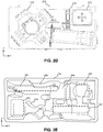
- FIG. 2D illustrates a top view of packaging configuration 200 for the multi-panel antenna in accordance with an embodiment.
- Feed assembly 208 can be placed on top of panel 206 so that the longest side of feed assembly 208 is aligned along the longest side of panel 206 (e.g., approximately along the X-axis).
- Feed assembly 208, multi-panel fastener 210, mounting assembly 212, and locking band 214 can be arranged to occupy a surface area smaller than the surface of center panel 202.
- FIG. 2E illustrates a top view of packaging insert 216 in accordance with an embodiment.
- Packaging insert 216 can include a slot 252 for packing feed assembly 208, a slot 260 for packing mounting assembly 212, a slot 262 for packing a power adapter (e.g., a power-over-Ethernet (PoE) adapter), a slot 268 for packing locking band 214, and a slot 264 for packing a power cord for the power adaptor.
- Packaging insert 216 can also include a side- wall 254 that holds a distal end of multi-panel fastener 210, and a side-wall 256 that holds a proximal end of multi-panel fastener 210.
- multi-panel fastener 210 can slide into packaging insert 216 so that its distal end rests against side-wall 254, and so that its proximal end rests at least against side-wall 256.
- the proximal end of multi-panel fastener 210 can rest between side walls 256 and 258.
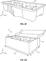
- FIG. 2F illustrates an angled view of packaging insert 216 in accordance with an embodiment.
- packaging insert 216 can be made by using a mold to create a contour on a pliable material.
- packaging insert 216 include molded cardboard, molded plastic, or molded polystyrene.
- FIG. 2G illustrates an angled view of packaging insert 216 inside a container 270 in a accordance with an embodiment.
- Container 270 can be used to contain and protect a multi-panel antenna kit. Specifically, the stack of panels 202, 204, and 206 can be placed into container 270 so that they rest on a floor inside container 270, and packaging insert 216 can be placed on top of the stacked panels. The remaining components of the kit can be inserted into their corresponding slots formed on insert 216. The slots created on insert 216 can prevent the kit components from shifting or bumping into each other while the kit is being shipped or otherwise transported to another location (e.g., transported to an antenna tower during deployment).
- container 270 can have a depth 272 between ten percent and twenty percent wider than one third of the width of the assembled multi-panel antenna. Moreover, container 270 can have a length 274 between five percent and fifteen percent longer than the height of the multi-panel antenna. Depth 272 can be between 12.7 cm (5") and 15.2 cm (6"), length 274 can be between 27.9 cm (11") and 30.5 cm (12"), and container 270 can have a height 276 that is between 10.2 cm (4") and 12.7 cm (5"). For example, depth 272 can be approximately 13.3 cm (5.25"), length 274 can be approximately 29.2 cm (11.5"), and height 726 can be approximately 11.4 cm (4.5").
- the depth of container 270 can be approximately one third the width of an assembled antenna, and height 276 can be less than the depth of the assembled antenna (e.g., when packaging antenna 100 with a width 36.2 cm (14.25”) and depth 18.4 cm (7.24”)).
- FIG. 3A illustrates an exploded view of the three-panel antenna system 300 in accordance with an embodiment.
- a center panel 302 can include a set of openings 316 and 318 for coupling a multi-panel fastener 310 to a convex side (e.g., the rear side) of center panel 302.
- openings 316 and 318 may be a part of a snap-fit coupler that can secure multi-panel fastener 310 onto the convex side of antenna system 300.
- Center panel 302 can also include an opening 314 for passing a proximal end of a feed assembly 308 toward multi-panel fastener 310. Coupling the proximal end of feed assembly 308 with multi-panel fastener 310 may secure feed assembly 308 to antenna system 300, and may also further secure multi-panel fastener 310 to panels 302, 304, and 306.
- Multi-panel fastener 310 can include a threaded coupler 350 that can be used to couple multi-panel fastener 310 to a mounting assembly 312, or to any other type of mountain equipment, such as a threaded pipe.
- mounting assembly 312 can include a mounting bracket 352, a ball joint 354 that can be coupled to mounting bracket 352 (e.g., with a screw).
- Mounting assembly 312 can also include a lock nut 356 that may be positioned between mounting bracket 352 and ball joint 354, and can mate with threaded coupler 350 of multi-panel fastener 310.
- Ball joint 354 can include a curved convex surface (e.g., a spherical, or near-spherical surface) that can mate with a central orifice (e.g., a curved concave surface) at threaded coupler 350, which can allow a user to adjust an azimuth, elevation, or rotational angle of the parabolic reflector.
- threaded coupler 356 to threaded coupler 350, which increases the friction between ball joint 354 and threaded coupler 350. Coupling threaded coupler 356 to threaded coupler 350 effectively couples multi-panel fastener 310 (and the parabolic reflector) to mounting assembly 312, and the increased friction locks the parabolic reflector into place.
- the panels may be constructed from a material suitable for reflecting radio signals toward feed assembly 308, such as aluminum.
- Aluminum may provide advantages over other materials, such as a relatively high strength-to-weight ratio, and a relatively simpler manufacturing process. Aluminum may also be polished to increase the reflectivity of the surface.
- panels 302, 304, and/or 306 may be manufactured from steel that may be finished with a nickel or chromium plating.
- panels 302, 304, and/or 306 may be manufactured from metal, ceramic, and/or plastic composites that may have an aluminum-plated surface or other reflective overlays. While the examples above describe manufacturing reflector panels using aluminum, nickel, and/or chromium, any other materials that have the aforementioned structural and reflective properties may be used in addition to, or in place of, aluminum, nickel, and/or chromium.
- reflector panels 302, 304, and/or 306 may have the same or different surface features and patterns.
- center reflector panel 302 may have a solid surface that is free of any features that may create a grid, screen, or mesh-like appearance (e.g., a grid of indents, openings, or through-holes). Manufacturing a solid surface may be achieved with a simpler process than manufacturing a mesh-like surface, at the cost of retaining unnecessary weight.
- side reflector panels 304 and 306 may be manufactured with a plurality of openings that may produce a grid, screen, or mesh-like appearance.
- openings can minimize the weight of side reflector panels 304 and 306, and may minimize environmental loads on panels 304 and 306, such as from wind, snow, rain, and ice.
- the size of the openings may have a diameter less than 1/10 of a wavelength for the radio signals that are to be reflected toward, and captured by, a set of feed pins in feed assembly 308.
- Such size constraints for the openings may allow side panels 304 and 306 to maintain similar, if not equivalent, reflective properties as the solid surface of central panel 302.
- Panels 302, 304, and 306 may be connected to each other in a simple assembly process that does not compromise the rigidity or integrity of the parabolic reflector when exposed to wind, rain, and/or other elemental forces.
- the simple assembly process should be simple enough for an untrained technician to assemble directional antenna system 300 in the field.
- the assembly process may be realized by a connecting system or locking mechanisms that may minimize the use of additional parts, tools, time, and skill required to lock and/or unlock side panels 304 and 306 to/from center panel 302.
- One or more types of known locking mechanisms and methods may be used to connect side panels 304 and 306 to center panel 302, regardless of whether panels 302, 304, and 306 are aligned vertically or horizontally.
- the locking mechanisms may enable panels 302, 304, and 306 to be fastened to each other, for example, by snapping them together, hooking or sliding them to interlock, etc.
- panels 302, 304, and 306 may be permanently interlocked.
- the panels may be separated simply by reversing the steps of the assembly process, which may involve also triggering a release before separating two adjoined components of directional antenna system 300.
- FIG. 3B illustrates an exploded top view of three-panel directional antenna system 300 in accordance with an embodiment.
- center panel 302 can include angled edges 324 and 326 that may extend from a rear (convex) surface of antenna system 300 from opposing sides of center panel 302.
- Side panels 304 and 306 can also include angled edges 328 and 330, respectively, along at least one side that may be fastened to center panel 302.
- Angled edge 328 of side panel 304 can be mated with angled edge 324 of center panel 302, and angled edge 330 of side panel 306 can be mated with angled edge 326 of center panel 302.
- angled edges 324 and 328 can include couplers for fastening side panel 304 to center panel 302.
- angled edges 326 and 330 can include couplers for coupling side panel 306 to center panel 302.
- angled edges 324 and 328 can include one or more post and slot couplers.
- multi-panel fastener 310 can include a pair of sleeves 332 and 334 that can further fasten side panels 304 and 306 to center panel 302. For example, after side panels 304 and 306 are coupled to center panel 302, sleeve 332 can slide over a portion of angled edges 324 and 328, and sleeve 334 can slide over a portion of angled edges 326 and 330.
- Multi-panel fastener 310 can also include an opening 320, which can be used to fasten feed assembly 308 to multi-panel fastener 310.
- feed assembly 308 can include a wedge anchor 322, or any other type of fastener that can interlock with opening 320.
- Wedge anchor 322 allows a user to secure inter-panel fastener 110 to center panel 302 without requiring additional tools, such as a screw and screw driver.
- a proximal end of feed assembly 308 can be passed through an opening of center panel 302 and inserted into an opening of multi-panel fastener 310, at which point wedge anchor 322 can mate with opening 320 to fasten feed assembly 308 to multi-panel fastener 310.
- Wedge anchor 322 can include a release button that protrudes past opening 320 on a top surface of multi-panel fastener 310. A user may press on the release button to disengage wedge anchor 322 from opening 320, and release feed assembly 308 from multi-panel fastener 310, without requiring additional tools for disassembling antenna system 300.
- FIG. 3C illustrates an exploded bottom view of three-panel directed antenna system 300 in accordance with an embodiment.
- feed assembly 308 can house a radio transceiver and one or more feed pins.
- the radio transceiver can generate RF signals that radiate from the antenna feed pins at a distal end of feed assembly 308.
- a proximal end of feed assembly 308 can include an interface port 338 that can provide power and/or a network connection to the radio transceiver housed inside feed assembly 308.
- interface port 338 can include an Ethernet port (e.g., a Power-over-Ethernet port), a Universal Serial Bus (USB) port, an IEEE 1394 (e.g., Firewire) port, a Thunderbolt port, or any other interface port now known or later developed.
- Multi-panel fastener 310 can include an opening 340 for exposing network port 338. When feed assembly 308 is mated with multi-panel fastener 310, interface port 338 may be exposed via opening 340.
- FIG. 3D illustrates an exploded side view of three-panel directed antenna system 300 in accordance with an embodiment.
- angled edge 328 of side panel 304 can include an edge segment 342.
- sleeve 332 may slide over edge segment 342 to prevent panel 304 from sliding along a Y-axis.
- FIG. 3E illustrates a curved receptacle surface 358 on a distal end of multi- panel fastener 310 in accordance with an embodiment.
- the proximal end of multi-panel fastener 310 can be coupled to center panel 302, and the distal end can include a central orifice 358 that may be coupled to ball joint 354, and can include a threaded circular outer surface for screwing a lock nut 356 to threaded coupler 350 on the distal end of multi-panel fastener 310.
- central orifice 358 can include a curved concave surface, with a curvature substantially similar to the curved convex surface of ball joint 354.
- Screwing lock nut 356 to threaded coupler 350 may effectively secure ball joint 354 to multi-panel fastener 310.
- Ball joint 356 can be coupled to mounting bracket 352 via a screw 360, and can include a set of prongs (e.g., four prongs positioned in a square configuration) that insert into a corresponding set of holes on mounting bracket 352 to prevent ball joint 356 from rotating.
- the curved surface of ball joint 354 may be pressed against the curved surface of central orifice 358 by tightening (e.g., via a rotating motion) lock nut 356 to threaded coupler 358 so that ball joint 354 is in between lock nut 354 and threaded coupler 350.
- mounting assembly 310 may include a door 360 to cover a network cable (not shown) that may be connected to antenna feed assembly 308 (not shown).
- door 360 may be crescent-shaped, and may be attached to a base of multi-panel fastener 310 and/or to the convex outer side of center reflector panel 302.
- FIG. 4A illustrates a process 400 for packaging a multi-panel directional antenna 400 in accordance with an embodiment.
- a factory worker may place the reflector panels into a container, in a stacked configuration (operation 402), and may place a packaging insert into the container, on top of the stacked reflector panels (operation 404).
- the factory worker may also place the mounting assembly and the antenna feed assembly into the packaging insert, either before or after placing the insert into the container (operation 406).
- the factory worker may then close the container (operation 408) and can seal the container (operation 410).
- the individual panels may be wrapped in plastic, polystyrene foam (e.g., Styrofoam), bubble wrap, paper, or any shielding or dampening material that may prevent the panels from getting scratched or bumping into each other during shipping.
- placing the panels into the container may involve sliding the individual panels into slots within a packaging insert at a bottom of the container, such that the slots may cause the panels to stand on one edge, with the concave side of the individual panels facing one side of the box.
- securing the panels within the container may involve sliding another packaging insert on a top edge of the individual panels, to prevent the panels from bumping into each other during shipping.
- the packaging inserts at the bottom surface and top surface of the container may include slots holding the mounting assembly and antenna feed assembly to prevent them from bumping onto each other or the reflector panels during shipping.
- FIG. 4B illustrates a process 450 for assembling a multi-panel directional antenna 400 in accordance with an embodiment.
- An end-user may install the directional antenna by first aligning inter-panel fasteners of the side reflector panels with corresponding inter-panel fasteners of the center reflector panels (operation 452).
- the inter-panel fasteners may include post and slot couplings along an angled edge of the reflector panels.
- the end-user may then fasten the individual reflector panels to each other to form a parabolic reflector (operation 454). If the parabolic reflector is formed from three individual panels, fastening the panels may involve fastening the side reflector panels to the center reflector panel.
- the end-user may also fasten the mounting assembly to a convex side of the center reflector panel (operation 456), and may fasten the antenna feed assembly to a concave side of the center reflector panel (operation 458).
- the end-user may then mount the directional antenna onto a mounting surface, such as a wall or a pole, by fastening the mounting assembly to the mounting surface (operation 460).
- a mounting surface such as a wall or a pole
- the end-user can put the antenna to use by aiming the directional antenna toward a remote directional antenna (operation 462), and connecting a network cable to a network port of the antenna feed assembly (operation 464)
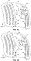
- FIG. 5A illustrates a set of panels being aligned during a panel assembly process in accordance with an embodiment.
- side panels 504 and 506 can be moved toward a center panel 502, at a slightly higher (or lower) elevation than center panel 502 so that a set of posts along angled edges 508 and 510 can pass through corresponding slots along angled edges 512 and 514.
- a slot and post coupler implements an inter-panel fastener that allows a side panel to be coupled to center panel 502.
- a slot 516 can include an elongated shape, with a wider opening along a segment of slot 516 (e.g., along a center segment of slot 516).
- a corresponding post 518 can include a wider head at the tip than along the rest of post 518.
- the wider opening along slot 516 may be sufficiently wide to allow the head of post 518 to pass through slot 516 so that angled edge 508 and the head of post 518 are at opposing sides of angled edge 512.
- the remainder of slot 516 may be sufficiently narrow to prevent the head of post 518 from passing through slot 516 when the head of post 518 is not aligned with the wider opening of slot 516.
- FIG. 5B illustrates a set of panels being fastened during a panel assembly process in accordance with an embodiment.
- side panels 506 and 508 may be slid along a Y-axis (e.g., downward) to fasten a set of couplings along the angled edges.
- sliding panel 504 along the Y-axis e.g., downward
- Fastening the couplings along angled edges 508 and 512 can prevent panel 504 from moving along an X-axis and/or a Z-axis with respect to panel 502, but may not prevent panel 504 from moving along at least one direction along the Y-axis (e.g., downward).
- an additional fastener may be used to secure side panels 504 and 506 to center panel 502 along at least the Y-axis.
- FIG. 5C illustrates a mounting assembly being fastened to a set of panels during a panel assembly process in accordance with an embodiment.
- a multi-panel fastener 550 may be fastened to center panel 502, which can also prevent side panels 504 and 506 from moving along a Y-axis.
- Multi-panel fastener 550 can include a sleeve 514 that can slide over an edge segment 512 of panel 504, and can include another sleeve 516 that may slide over an edge segment of panel 506 (not shown).
- center panel 502 and multi-panel fastener 550 can include a set of fasteners for fastening multi-panel fastener 550 to center panel 502, such as a wedge anchor, a snap fastener, or any other fastener that may produce a rigid coupling between center panel 502 and multi-panel fastener 550.
- center panel 502 can include a pair of openings 520 and 522 for coupling multi-panel fastener 510 to center panel 502.
- Multi-panel fastener 550 can include a set of fasteners 524 and 526 (e.g., wedge anchors) that can fasten multi-panel fastener 550 to openings 520 and 522, respectively.
- FIG. 5D illustrates a rear angled view of an assembled multi-panel directional antenna 500 in accordance with an embodiment.
- the fasteners along the angled edges of panels 502, 504, and 506 can fasten side panels 504 and 506 to center panel 504 along the X-axis and/or the Z-axis
- multi-panel fastener 550 can fasten side panels 504 and 506 to center panel 504 along the X-axis and the Y-axis.
- multi-panel fastener 550 can assist securing panels 502, 504, and 506 to each other to form a rigid parabolic reflector, and can also include a mounting assembly 530 for mounting directional antenna 500 onto an external surface.
- FIG. 6A illustrates a close-up view of a mounting assembly 600 in accordance with an embodiment.
- mounting assembly 600 can include an antenna- feed fastener 602 for fastening an antenna feed to mounting assembly 600.
- a back side of the feed assembly may be inserted into antenna feed fastener 602, and a wedge-anchor fastener (not shown) can anchor against an opening on mounting assembly 600 (not shown).
- Mounting assembly 600 can also include a set of center-panel fasteners 604 and 606, and a set of side-panel fasteners 608 and 610.
- Center-panel fasteners 604 and 606 may include a wedge-anchor fastener, which may fasten mounting assembly 600 to a center panel of a parabolic reflector.
- Side-panel fastener 608, for example, can include a sleeve 614 which may be defined by a curved surface 616, as well as a pair of stops 618 and 620.
- Curved surface 616 may wrap around the mated the curved edge segments of a side panel and center panel of the parabolic reflector, and stops 618 and 620 may prevent the side panel from moving along the Y-axis (e.g., the vertical axis).
- FIG. 6B illustrates the mounting assembly 600 being coupled to a rear surface of a multi-panel directional antenna in accordance with an embodiment.
- a sleeve 622 of side-panel fastener 610 may slide over a curved-edge segment 630 of a side panel 628, and stops 624 and 626 may slide into a pair of recessed segments of side panel 628 that define curved-edge segment 630.
- a screw (not shown) can optionally be inserted into a set of screw -holes 640 on the side edges of panels 628 and 638 to further secure panel 628 onto panel 638.
- FIG. 7A illustrates a front view of an assembled multi-panel directional antenna
- FIG. 7B illustrates a rear view of the assembled multi-panel directional antenna in accordance with an embodiment.
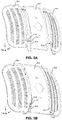
- the side panels of directional antenna 700 can include perforated side panels.
- side panel 704 can include a plurality of holes arranged in multiple columns that each span a Y-axis. In some embodiments, the columns may be equally spaced from each other along an X-axis. Alternatively, the columns may be organized into two or more groups of rows, where the spacing between two neighboring groups is larger than the spacing between two neighboring columns within a group.
- the side panels can include rounded corners, and the perforated columns near the rounded corners may be shorter than other perforated columns away from the rounded corner.
- the perforated columns in column group 708 may be shorter closer to an outer edge of side panel 704, whereas the perforated columns of a column group 706 may be of equal height.
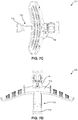
- FIG. 7C illustrates a side view of an assembled multi-panel directional antenna 700 in accordance with an embodiment.
- directional antenna 700 can include a parabolic reflector 702 that can have a parabolic shape along a Y-axis. The parabolic shape can reflect radio waves toward a front end 712 of feed assembly 710.
- FIG. 7D illustrates a top view of an assembled multi-panel directional antenna 700 in accordance with an embodiment.
- parabolic reflector 702 can have a parabolic shape along a X-axis, such that the parabolic shape can reflect radio waves toward front end 712 of feed assembly 710.
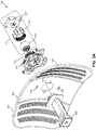
- FIG. 7E illustrates an exploded view of antenna feed assembly 710 in accordance with an embodiment.
- Antenna feed assembly 710 can include a feed housing 752, which may house an antenna tube, a sub-reflector 754, a printed circuit board 756, a battery, a interfacing connector 760, a radio transceiver, a feed conductor, feed pins 758, and director pins.
- the housing can have a closed end and an open end. The open end may be surrounded by a base collar that may be adapted to lay against the surface surrounding a central aperture of a parabolic reflector.
- the housing may be constructed from materials that may protect the feed components from outdoor exposure, such as fairly rigid plastics.
- the antenna tube may extend from inside the housing and may project past the open end of the housing. Similar to feed housing 752, the antenna tube may also have an open end and a closed end, and the dimensions of the antenna tube may be adjusted in accordance to the size of sub-reflector 754.
- An interfacing cable (not shown) may be routed through the tube and connected to the interfacing connector 760 (e.g., an Ethernet port).
- the exterior portion of the tube projecting outside of the housing may have a threaded portion for inserting into the aperture of the reflector and securing to the mounting assembly.
- Sub-reflector 754 can have a shape that may radiate waves toward the main parabolic reflector, and may be situated in the closed end portion of feed housing 752.
- the printed circuit board having RF control circuitry, may receive power from the battery that may be connected to the circuit board, or may receive power from the interfacing cable (e.g., a Power-over- Ethernet cable).
- the circuit board may serve as the platform for the interfacing connector, radio transceiver, feed conductor, feed pins, and director pins.
- interfacing connector 760 may be coupled to the radio transceiver for power and data input and output purposes, when configured with a digital cable.
- the radio transceiver may generate an F signal that can be coupled to the feed conductor, which in turn, can be coupled to the feed pins.
- Feed pins 758 may radiate the RF signal to sub-reflector 754, which then may radiates the RF signal to the parabolic reflector (e.g., reflector 714).
- the director pins which may be passive radiators or parasitic elements, may help focus or reradiate waves to feed pins 758 in order maximize the waves radiated from sub-reflector 754 to the parabolic reflector.
- FIG. 7F illustrates an exemplary integrated radio transceiver and feed 770 in accordance with an embodiment.
- radio transceiver and feed 770 can integrate the functions of a radio transceiver, the functions of an antenna feed conductor, and the functions of a conventional antenna feed mechanism.
- Integrated radio transceiver and feed 7700 may be located in antenna feed mechanism 710.
- Integrated radio transceiver and feed 770 may be assembled on a common substrate, which may be a multi-layer printed circuit board (PCB) 778.
- PCB printed circuit board
- Integrated radio transceiver and feed 770 can include a digital connector 771, which may be an Ethernet connector, a USB connector, or any other digital connector now known or later developed.
- a digital signal from a client station may be transmitted to, or received from, the digital connector 771 over a digital cable.
- the digital cable may include a power component.
- the power component may be provided over an Ethernet cable, a USB cable, or other equivalent digital cable.
- digital connector 771 may be coupled to a radio transceiver 773 via conductor 772.
- Conductor 772 may be implemented by a metal by a metal connector on a PCB 778.
- Radio transceiver 773 may be coupled to an antenna feed conductor 774, which in turn couples to antenna feed pins 775.
- Radio transceiver 773 can generate an RF signal that radiate from antenna feed pins 775 radiate toward an antenna reflector, such as toward a parabolic reflector panel, or sub-reflectors 777.
- the radiated signal may be modified and enhanced by director pins 776 and/or sub-reflectors 777.
- antenna feed pins 775 can include two pins that may be located on opposite sides of PCB 778, and the pins may be electrically connected together.
- an antenna feed pin 775 may implement a half wave-length dipole.
- director pins 776 and sub-reflectors 777 may modify away from that of a half-wave length dipole.
- director pins 776 may operate as passive radiators or parasitic elements.
- director pins 776 may not have a wired input. Rather, director pins 776 may absorb radio waves that have radiated from another active antenna element in proximity, such as feed pins 775, and may re-radiate the radio waves in phase with the active element so that director pins 776 may augments the total transmitted signal.
- An example of an antenna that uses passive radiators is the Yagi, which typically has a reflector behind the driven element, and one or more directors in front of the driven element, which may act respectively like a reflector and lenses in a flashlight to create a "beam.”
- parasitic elements may be used to alter the radiation parameters of nearby active elements.
- director pins 776 may be electrically isolated in integrated radio transceiver and feed 770. Alternatively, director pins 776 may be grounded. For example, director pins 776 can include two pins that may be inserted through PCB 208, such that two pins may remain at each side of PCB 208, as illustrated in FIG. 7F . Antenna feed pins 775 and director pins 776 may be mounted perpendicular to a surface of PCB 778. Moreover, antenna feed pins 775 and/or director pins 776 may be implemented with surface mounted (SMT) pins.
- SMT surface mounted
- antenna feed pins 775 and director pins 776 may allow the transmission of radio waves to be planar to the integrated radio transceiver and feed 770.
- the electric field may be tangential to the metal of PCB 778, such that at the metal surface, the electric field may be zero.
- antenna feed pins 775 and director pins 776 may emit approximately equal F and H plane radiation patterns that can provide for effective illumination of the antenna, thus increasing the microwave system efficiency.
- FIG. 7G illustrates another example of an integrated radio transceiver and feed 780 comprising a housing 781 with an antenna tube 783 in accordance with an embodiment.
- Housing 781 may be a weather-proof housing, such as a plastic housing that may enclose the elements of integrated radio transceiver and feed 780.
- Housing 781 may conform to the shape of sub-reflector 777. In some embodiments, housing 781 may permit interchangeability of the sub-reflector 777.
- sub-reflector 777 may reflect radiated waves 782 back toward a reflective antenna (e.g., a parabolic antenna reflector panel).
- the radiation pattern and parameters may be modified by sub-reflector antenna 777, which may be located near antenna feed pins 775.
- Director pins 776 and/or sub-reflector 777 can be selected to modify the antenna pattern and beam width, such as to improve the microwave system performance.
- tube 783 may also be adjusted to various lengths in order to accommodate reflectors of different sizes.
- a digital cable may be routed through tube 783, and can connect to digital connector 771.
- Digital connector 771 may have a weatherized connector, such as a weatherized Ethernet or USB connector.
- FIG. 8A illustrates an exemplary two-panel directional antenna 800 in accordance with an embodiment.
- Directional antenna 800 can include two panels 802 and 804 that together form a parabolic reflector.
- a mounting assembly 808 can be coupled to a rear (convex) side of the parabolic reflector
- a feed assembly 806 can be coupled to a front (concave) side of the parabolic reflector.
- FIG. 8B illustrates an exploded view of mounting assembly 808 in accordance with an embodiment.
- mounting assembly 808 can include a multi-panel fastener 810, with a proximal end that can include a flat surface with two or more openings for fastening multi-panel fastener 810 to a rear surface of side panels 802 and 804.
- the distal end of multi-panel fastener 810 can include a threaded circular outer surface for screwing a lock nut 814 to multi-panel fastener 810.
- Lock nut 814 and the distal end of multi-panel fastener 810 can each include an orifice for securing a ball joint 812 between multi-panel fastener 810 and lock nut 814.
- Ball joint 812 can include a set of prongs which can be coupled to a mounting base 816.
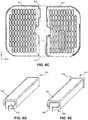
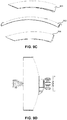
- FIG. 8C illustrates two panels 802 and 804 of the directional antenna in accordance with an embodiment.
- panels 802 and 804 can include a set of couplings, which can fasten panels 802 and 804 together.
- couplings 820 and 822 can each include a bore and sleeve coupling.
- panel 804 can include bores along an inside edge (e.g., for couplings 820 and 822), and panel 802 can include sleeves along an inside edge.
- panel 802 can include a bore for one coupling and a sleeve for another coupling, and panel 804 can include the corresponding bore and sleeve for coupling panel 804 to panel 802.
- a bore may snap-fit into a receiving sleeve.
- the sleeve on an inside edge of one panel may be positioned to couple with a bore on the inside edge of the other panel.
- coupling the bores to their corresponding sleeves may involve moving at least one panel along the Z-axis, to insert the bores into the corresponding sleeves.
- a bore may be slid into a sleeve.
- panels 802 and 804 may first be aligned along the X-axis and Z-axis, and one panel may then be moved along the Y-axis to slide the bores into the sleeves.
- the inner edge of panels 802 and 804 may have a semi-circularly shaped cutout along the middle section of the edge. When the inner edges of the panels are placed next to each other and vertically aligned, the cutouts form the reflector' s central aperture for receiving the antenna feed assembly.
- two or more panels may be coupled using a combination of one or more of an elbow lock seam; a z-clip fastener, a retention clip, a standing seam attachment bracket, and/or any other fastener now known or later developed.
- various interconnects may also be used to secure the panels together, such as a bolt, a screw, a pronged rivet, and a tension pin.
- FIG. 8D illustrates an exemplary bore-and-sleeve coupling 830 in accordance with an embodiment.
- Coupling 830 can include a bore 832, which can slide into a sleeve 834 along a Z-axis from either end of sleeve 834.
- Sleeve 834 can surround a portion of bore 832 along a Z-axis, which may secure bore 832 along an X-axis and Y-axis.
- FIG. 8E illustrates an exemplary bore-and-sleeve coupling 840 with a stopper 846 in accordance with an embodiment.
- coupling 840 can include a sleeve 844, which itself can include an opening 848 at one end, and a stopper 846 at an opposing end.
- a bore 842 can be slid into opening 848, until one end of bore 842 makes contact with stopper 846.
- FIG. 8F illustrates an assembled two-panel directional antenna 800 in accordance with an embodiment.
- FIG. 8G illustrates a front view of the assembled two-panel directional antenna 800
- FIG. 8H illustrates a back view of the assembled two- panel directional antenna 800 in accordance with an embodiment.
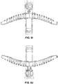
- FIG. 8I illustrates a top view of the assembled two-panel directional antenna 800
- FIG. 8J illustrates a bottom view of the assembled two-panel directional antenna 800 in accordance with an embodiment.
- FIG. 9A illustrates an exemplary three-panel directional antenna in accordance with an embodiment.
- the antenna system can include a reflector that may be formed from three panels 902, 904, and 906.
- panels 902, 904, and 906, and/or an antenna feed assembly 908 may be attached to, and fastened against, a mounting assembly 910.
- panels 904 and 906 may be fastened against center panel 902, and/or may also be fastened to each other.
- FIG. 9B illustrates an exploded view of the three-panel directional antenna in accordance with an embodiment.
- panels 902, 904, and 906 may be arranged in an overlapping formation to increase the structural rigidity of the reflector.
- center panel 802 may include a central opening for coupling feed assembly 908 to mounting assembly 910.
- side panels 804 and 806 may be essentially mirror images of each other, and each may have a substantially semi-circular cutout extending from an inner edge. When side panels 904 and 906 are aligned vertically with their inner edges touching one another, the cutouts may form the shape of the central opening on center panel 902 for receiving antenna feed assembly 908.
- central panel 902 may overlap a portion of side panels 904 and 906.
- panels 902, 904, and 906 may include a sliding track system to connect and hold panels 902, 904, and 906 in a configuration that forms the parabolic reflector.
- a track may be positioned along one or both of the top and bottom edges.
- a carriage may lie along one or both of the top and bottom edges.
- a track on center panel 902 may allow a carriage on side panels 904 and 906 to slide die panels 904 and 906 into place, until the central opening of center panel 902 is aligned with the central opening formed by side panels 904 and 906.
- a stopper may be provided along the tracks to limit movement of the carriages once they have slid side panels 904 and 906 to their target locations. Moreover, the panels of the parabolic reflector are further strengthened and stabilized when antenna feed assembly 908 is inserted into the central opening of the reflector, and antenna feed assembly 908 is connected to the base of mounting assembly 910.
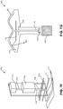
- FIG. 9C illustrates a packaging configuration for the disassembled three- panel directional antenna in accordance with an embodiment.
- panels 902, 904, and 906 may be packaged into a container in a stacked configuration, such that center panel 902 may be sandwiched between side panels 904 and 906.
- center panel 902 may be stacked above side panels 904 and 906, or may be stacked underneath side panels 904 and 906.
- panels 902, 904, and 906 may be stacked vertically within a container, with their concave surfaces facing toward a top surface or a bottom surface of the container.
- the stacked panels may be placed in the container so that panels 902, 904, and 906 may be stacked horizontally, with their concave surfaces facing toward a side surface of the container.
- FIG. 9D illustrates a side view of the assembled three-panel directional antenna in accordance with an embodiment.
- FIG. 9E illustrates a front view of the assembled three-panel directional antenna
- FIG. 9F illustrates a back view of the assembled three-panel directional antenna in accordance with an embodiment
- FIG. 9G illustrates a top view of the assembled three-panel directional antenna
- FIG. 9H illustrates a bottom view of the assembled three- panel directional antenna in accordance with an embodiment.
Landscapes
- Physics & Mathematics (AREA)
- Electromagnetism (AREA)
- Aerials With Secondary Devices (AREA)
- Engineering & Computer Science (AREA)
- Manufacturing & Machinery (AREA)
- Support Of Aerials (AREA)
Claims (6)
- Bausatz für ein Mehrpaneelantennensystem, wobei der Bausatz Folgendes umfasst:einen Satz von Reflektorpaneelen (104, 106, 108), der ein Mittenreflektorpaneel (104) und zwei Seitenreflektorpaneele (106, 108) beinhaltet,wobei ein jeweiliges Reflektorpaneel eine gekrümmte Oberfläche beinhaltet, die einen Abschnitt eines Parabolreflektors (102) für das Mehrpaneelantennensystem ausbildet, und wobei die Krümmungen des Mittenreflektorpaneels (104) und der zwei Seitenreflektorpaneele (106, 108) im Wesentlichen ähnlich sind, um Stapeln des Mittenreflektorpaneels und der zwei Seitenreflektorpaneele zu erleichtern;ein Mehrpaneelbefestigungselement (210) zum Zusammenkoppeln des Mittenreflektorpaneels und der zwei Seitenreflektorpaneele, um den Parabolreflektor auszubilden,eine Zuführungsbaugruppe (208) für das Mehrpaneelantennensystem;eine Montagebaugruppe (212); undeinen Behälter (270), der Folgendes umfasst:einen Einsatz (216), der im Innern des Behälters (270) oben auf den Reflektorpaneelen (104, 106, 108) ruht,wobei der Einsatz (216) das Mehrpaneelbefestigungselement (210), die Zuführungsbaugruppe (208) und die Montagebaugruppe (212) von den Reflektorpaneelen trennt, wobei der Einsatz (216) einen ausgeformten Einsatz beinhaltet, der Aufnahmen (252, 260, 262, 264, 268) für das Mehrpaneelbefestigungselement, die Montagebaugruppe und die Zuführungsbaugruppe beinhaltet, wobei der ausgeformte Einsatz (216) eine konvexe Krümmung aufweist, die die konkave Oberfläche der gestapelten Reflektorpaneele nachkonturiert, und wobei die Abmessungen des ausgeformten Einsatzes (216) Einsetzen des ausgeformten Einsatzes innerhalb des Behälters (270) und oben auf den am Boden des Behälters platzierten gestapelten Reflektorpaneelen erleichtern.
- Bausatz nach Anspruch 1, wobei die konvexe Krümmung des ausgeformten Einsatzes die gekrümmte Oberfläche eines jeweiligen Reflektorpaneels nachkonturiert.
- Bausatz nach Anspruch 1, wobei die konvexe Krümmung des ausgeformten Einsatzes dafür ausgelegt ist, das Mittenreflektorpaneel und die zwei Seitenreflektorpaneele in der gestapelten Konfiguration aufzunehmen; oderder ausgeformte Einsatz dafür ausgelegt ist, das Mittenreflektorpaneel und die zwei Seitenreflektorpaneele getrennt aufzunehmen,wobei der ausgeformte Einsatz das Mittenreflektorpaneel und die zwei Seitenreflektorpaneele in die gestapelte Konfiguration hinein anordnet.
- Bausatz nach Anspruch 1, wobei die Reflektorpaneele mit einem Abschirm- oder Dämpfungsmaterial umwickelt sind, um die Reflektorpaneele zu schützen.
- Bausatz nach Anspruch 1, wobei die Montagebaugruppe Folgendes umfasst:eine Montagehalterung;ein Kugelgelenk, gekoppelt an die Montagehalterung; undeine Kontermutter zwischen dem Kugelgelenkt und der Montagehalterung, wobei die Kontermutter einsetzbar ist zum Koppeln der Montagebaugruppe an eine Gewindekupplung an einem Distalabschnitt des Mehrpaneelbefestigungselements.
- Bausatz nach Anspruch 1, ferner umfassend ein oder mehrere der Folgenden:eine Pfostenarretierschelle;ein Netzteil; undeine Power-over-Ethernet-Stromversorgung bzw. PoE-Stromversorgung; undein Stromversorgungskabel.
Priority Applications (3)
| Application Number | Priority Date | Filing Date | Title |
|---|---|---|---|
| EP21185690.1A EP3913736B1 (de) | 2014-12-02 | 2016-01-15 | Antennensystem mit mehreren paneelen |
| PL20162136T PL3686996T3 (pl) | 2014-12-02 | 2016-01-15 | Wielopanelowy układ antenowy |
| EP23186642.7A EP4254667A3 (de) | 2014-12-02 | 2016-01-15 | Antennensystem mit mehreren paneelen |
Applications Claiming Priority (5)
| Application Number | Priority Date | Filing Date | Title |
|---|---|---|---|
| US201462086525P | 2014-12-02 | 2014-12-02 | |
| US201562191232P | 2015-07-10 | 2015-07-10 | |
| US14/886,744 US9847584B2 (en) | 2014-12-02 | 2015-10-19 | Multi-panel antenna system |
| PCT/US2016/013729 WO2016090386A2 (en) | 2014-12-02 | 2016-01-15 | Multi-panel antenna system |
| EP16702299.5A EP3227957B1 (de) | 2014-12-02 | 2016-01-15 | Antennensystem mit mehreren paneelen |
Related Parent Applications (1)
| Application Number | Title | Priority Date | Filing Date |
|---|---|---|---|
| EP16702299.5A Division EP3227957B1 (de) | 2014-12-02 | 2016-01-15 | Antennensystem mit mehreren paneelen |
Related Child Applications (3)
| Application Number | Title | Priority Date | Filing Date |
|---|---|---|---|
| EP23186642.7A Division EP4254667A3 (de) | 2014-12-02 | 2016-01-15 | Antennensystem mit mehreren paneelen |
| EP21185690.1A Division-Into EP3913736B1 (de) | 2014-12-02 | 2016-01-15 | Antennensystem mit mehreren paneelen |
| EP21185690.1A Division EP3913736B1 (de) | 2014-12-02 | 2016-01-15 | Antennensystem mit mehreren paneelen |
Publications (2)
| Publication Number | Publication Date |
|---|---|
| EP3686996A1 EP3686996A1 (de) | 2020-07-29 |
| EP3686996B1 true EP3686996B1 (de) | 2021-09-08 |
Family
ID=56079762
Family Applications (4)
| Application Number | Title | Priority Date | Filing Date |
|---|---|---|---|
| EP16702299.5A Active EP3227957B1 (de) | 2014-12-02 | 2016-01-15 | Antennensystem mit mehreren paneelen |
| EP23186642.7A Pending EP4254667A3 (de) | 2014-12-02 | 2016-01-15 | Antennensystem mit mehreren paneelen |
| EP20162136.4A Active EP3686996B1 (de) | 2014-12-02 | 2016-01-15 | Antennensystem mit mehreren paneelen |
| EP21185690.1A Active EP3913736B1 (de) | 2014-12-02 | 2016-01-15 | Antennensystem mit mehreren paneelen |
Family Applications Before (2)
| Application Number | Title | Priority Date | Filing Date |
|---|---|---|---|
| EP16702299.5A Active EP3227957B1 (de) | 2014-12-02 | 2016-01-15 | Antennensystem mit mehreren paneelen |
| EP23186642.7A Pending EP4254667A3 (de) | 2014-12-02 | 2016-01-15 | Antennensystem mit mehreren paneelen |
Family Applications After (1)
| Application Number | Title | Priority Date | Filing Date |
|---|---|---|---|
| EP21185690.1A Active EP3913736B1 (de) | 2014-12-02 | 2016-01-15 | Antennensystem mit mehreren paneelen |
Country Status (8)
| Country | Link |
|---|---|
| US (2) | US9847584B2 (de) |
| EP (4) | EP3227957B1 (de) |
| CN (2) | CN105762481B (de) |
| CY (1) | CY1123373T1 (de) |
| ES (1) | ES2797105T3 (de) |
| LT (1) | LT3227957T (de) |
| PL (3) | PL3913736T3 (de) |
| WO (1) | WO2016090386A2 (de) |
Families Citing this family (21)
| Publication number | Priority date | Publication date | Assignee | Title |
|---|---|---|---|---|
| US9847584B2 (en) * | 2014-12-02 | 2017-12-19 | Ubiquiti Networks, Inc. | Multi-panel antenna system |
| USD800100S1 (en) | 2015-05-01 | 2017-10-17 | Ubiquiti Networks, Inc. | Multiple panel reflector dish antenna |
| CN107535062B (zh) * | 2015-05-14 | 2019-11-19 | 株式会社东芝 | 电子设备以及电子设备的制造方法 |
| US10153559B1 (en) * | 2016-06-23 | 2018-12-11 | Harris Corporation | Modular center fed reflector antenna system |
| USD816069S1 (en) * | 2016-06-28 | 2018-04-24 | Jasco Products Company LLC | Antenna |
| WO2018191383A1 (en) * | 2017-04-11 | 2018-10-18 | Carpe Diem Technologies, Inc. | System and method of manufacturing a cylindrical nanoimprint lithography master |
| CN107946771B (zh) * | 2017-11-21 | 2019-08-16 | 上海航天测控通信研究所 | 开口波导偶极子馈电抛物线反射面短背射天线的馈源结构 |
| US11252832B2 (en) | 2017-12-08 | 2022-02-15 | Hewlett-Packard Development Company, L.P. | Display devices with push-button assemblies |
| CN109301441B (zh) * | 2018-10-29 | 2024-02-20 | 广东中元创新科技有限公司 | 一种可降低多径衰减的八木天线 |
| CN209766630U (zh) * | 2018-12-11 | 2019-12-10 | 广东侨华科技有限公司 | 室外天线 |
| CN110034995A (zh) * | 2019-02-27 | 2019-07-19 | 浙江胜百信息科技有限公司 | 一种户外天线网桥 |
| US10847892B2 (en) * | 2019-03-18 | 2020-11-24 | Antenna World Inc. | Wide band log periodic reflector antenna for cellular and Wifi |
| CN110109230B (zh) * | 2019-05-24 | 2020-07-28 | 西安交通大学 | 一种非球面类复杂曲面工件的智能化拼接装配方法 |
| US10893264B1 (en) | 2019-06-21 | 2021-01-12 | Voxx International Corporation | Traffic light-type signal strength meter/indicator linked to an antenna AGC circuit |
| BR102019023048A2 (pt) * | 2019-11-01 | 2021-05-18 | Vivensis Pr Century Indústria E Comércio Ltda | disposição introduzida em antena de recepção doméstica |
| CN111540998B (zh) * | 2020-05-09 | 2021-04-30 | 捷宇五金电子(深圳)有限公司 | 一种应用于5g移动通信的便携式天线 |
| TWI755032B (zh) * | 2020-08-18 | 2022-02-11 | 國立中正大學 | 電磁波繞行式結構及電磁波繞行方法 |
| US12074372B2 (en) | 2020-09-23 | 2024-08-27 | Nokia Solutions And Networks Oy | Method and apparatus for antenna with notched multi-element reflector |
| EP4305704A4 (de) * | 2021-03-08 | 2025-02-26 | Datapath, Inc. | Transportables satellitenantennenendgerät |
| TW202406207A (zh) * | 2022-04-20 | 2024-02-01 | 美商阿泰訊控股公司 | 改進的rfid天線 |
| KR102571852B1 (ko) * | 2023-06-27 | 2023-08-29 | 국방과학연구소 | 볼륨형 전파흡수구조체 어셈블리 |
Family Cites Families (45)
| Publication number | Priority date | Publication date | Assignee | Title |
|---|---|---|---|---|
| US3140491A (en) * | 1963-01-24 | 1964-07-07 | Boeing Co | Diffraction shield consisting of notched ring which frames passive reflector |
| US3599218A (en) * | 1968-09-11 | 1971-08-10 | Trw Inc | Lightweight collapsible dish structure and parabolic reflector embodying same |
| US4378560A (en) * | 1980-05-22 | 1983-03-29 | Khorsand Hossein M | Reflector support structure |
| US4893132A (en) * | 1988-10-28 | 1990-01-09 | Radiation Systems, Inc. Technical Products Division | Assembly system for maintaining reflector segments of an antenna in precision alignment |
| US5061945A (en) * | 1990-02-12 | 1991-10-29 | Hull Harold L | Portable satellite antenna system |
| US5050976A (en) * | 1990-06-28 | 1991-09-24 | The United States Of America As Represented By The Secretary Of The Air Force | Hub and petal apparatus for mosaic mirrors and millimeter wave antennas |
| JP2853658B2 (ja) * | 1996-06-04 | 1999-02-03 | 日本電気株式会社 | アンテナ支持構造 |
| US6340956B1 (en) * | 1999-11-12 | 2002-01-22 | Leland H. Bowen | Collapsible impulse radiating antenna |
| EP1134838A1 (de) * | 2000-03-14 | 2001-09-19 | Lucent Technologies Inc. | Antennengehäuse (Radom) |
| US6531992B1 (en) * | 2001-03-20 | 2003-03-11 | Netune Communications, Inc. | Back frame assembly |
| EP1425820A1 (de) * | 2001-09-13 | 2004-06-09 | Fractus, S.A. | Mehrfach abgestufte und flächenausfüllende masse-ebenen für miniatur- und mehrband-antennen |
| US7218289B2 (en) * | 2005-09-08 | 2007-05-15 | Norsat International Inc. | Portable high-speed data and broadcast-quality video terminal for terrestrial and satellite communications |
| US7324057B2 (en) * | 2005-09-26 | 2008-01-29 | Gideon Argaman | Low wind load parabolic dish antenna fed by crosspolarized printed dipoles |
| US7443355B2 (en) * | 2006-11-09 | 2008-10-28 | Kvh Industries, Inc. | Antenna feed-tube-to-amplifier coupling |
| US8816923B2 (en) * | 2007-02-07 | 2014-08-26 | Electronic Controlled Systems, Inc. | Motorized satellite television antenna system |
| US7969375B2 (en) * | 2007-05-10 | 2011-06-28 | Viasat, Inc. | Spherical motor positioning |
| US7965256B2 (en) | 2007-05-24 | 2011-06-21 | Asc Signal Corporation | Segmented antenna reflector |
| US7872614B2 (en) * | 2007-10-31 | 2011-01-18 | Communications & Power Industries, Inc. | System and method for providing a deployable phasing structure |
| US7755564B2 (en) * | 2007-10-31 | 2010-07-13 | Communications & Power Industries, Inc. | Deployable phasing system for emulating reflective surfaces |
| US7859479B2 (en) * | 2008-03-25 | 2010-12-28 | The United States Of America As Represented By The Secretary Of The Air Force | Antenna for compact satellite terminal |
| US8497810B2 (en) * | 2009-03-18 | 2013-07-30 | Kvh Industries, Inc. | Multi-band antenna system for satellite communications |
| US8466847B2 (en) * | 2009-06-04 | 2013-06-18 | Ubiquiti Networks, Inc. | Microwave system |
| CN102239599B (zh) | 2009-06-04 | 2015-06-03 | 优波网络公司 | 天线馈电系统 |
| WO2010144831A2 (en) * | 2009-06-12 | 2010-12-16 | Strydesky Gregory L | Segmented antenna reflector |
| EP2532035A1 (de) * | 2010-05-06 | 2012-12-12 | The Government of the United States of America as represented by the Secretary of the Navy | Einsetzbarer satellitenreflektor mit niedriger passiver intermodulation |
| US8373589B2 (en) * | 2010-05-26 | 2013-02-12 | Detect, Inc. | Rotational parabolic antenna with various feed configurations |
| US8405570B2 (en) * | 2010-05-27 | 2013-03-26 | Andrew Llc | Segmented antenna reflector with shield |
| KR101113822B1 (ko) * | 2010-06-15 | 2012-02-29 | (주)인텔리안테크놀로지스 | 위성안테나용 반사경조립체 및 그 제조방법 |
| FR2966646B1 (fr) * | 2010-10-26 | 2013-10-04 | Thales Sa | Positionneur d'antenne parabolique |
| KR101166728B1 (ko) * | 2011-01-27 | 2012-07-19 | (주)인텔리안테크놀로지스 | 다중 편파 위성 신호를 위한 편파기 회전 기구 및 이를 구비한 위성 신호 수신 장치 |
| KR101172437B1 (ko) * | 2011-03-09 | 2012-08-08 | (주)인텔리안테크놀로지스 | 다중 편파 송수신이 가능한 위성 통신용 안테나 |
| KR101209775B1 (ko) * | 2011-03-15 | 2012-12-07 | (주)인텔리안테크놀로지스 | 위성 통신용 안테나 |
| US9401546B2 (en) * | 2011-09-20 | 2016-07-26 | Lockheed Martin Corporation | mmW low sidelobe constant beamwidth scanning antenna system |
| IL217059A (en) * | 2011-12-18 | 2015-07-30 | Or Hama Energy Ltd | Lightweight system and method for dynamic solar energy utilization |
| US9350083B2 (en) | 2012-03-10 | 2016-05-24 | Harris Corporation | Portable satellite communication system |
| US9225071B2 (en) | 2012-04-06 | 2015-12-29 | Ubiquiti Networks, Inc. | Antenna assembly for long-range high-speed wireless communications |
| US9136610B2 (en) * | 2012-10-30 | 2015-09-15 | Viasat, Inc. | Satellite antenna adapter for tripod |
| US9293836B2 (en) * | 2012-11-06 | 2016-03-22 | Kabushiki Kaisha Toshiba | Antenna apparatus |
| US9531067B2 (en) | 2013-02-08 | 2016-12-27 | Ubiquiti Networks, Inc. | Adjustable-tilt housing with flattened dome shape, array antenna, and bracket mount |
| US9991581B2 (en) * | 2013-04-26 | 2018-06-05 | RF elements s.r.o. | Ball joint mounts |
| EP2804259B1 (de) * | 2013-05-15 | 2019-09-18 | Alcatel- Lucent Shanghai Bell Co., Ltd | Radom für eine Antenne mit Konkavreflektor |
| US10622698B2 (en) * | 2013-08-02 | 2020-04-14 | Windmill International, Inc. | Antenna positioning system with automated skewed positioning |
| TWI552433B (zh) * | 2014-07-14 | 2016-10-01 | 啟碁科技股份有限公司 | 可折疊收納之衛星天線 |
| KR101457931B1 (ko) * | 2014-07-15 | 2014-11-04 | 삼성탈레스 주식회사 | 자석 절개선을 가지는 운반용 반사판 안테나 |
| US9847584B2 (en) * | 2014-12-02 | 2017-12-19 | Ubiquiti Networks, Inc. | Multi-panel antenna system |
-
2015
- 2015-10-19 US US14/886,744 patent/US9847584B2/en active Active
- 2015-12-02 CN CN201510868094.9A patent/CN105762481B/zh active Active
- 2015-12-02 CN CN201520984373.7U patent/CN205657158U/zh not_active Expired - Lifetime
-
2016
- 2016-01-04 US US14/987,674 patent/US9698491B2/en active Active
- 2016-01-15 EP EP16702299.5A patent/EP3227957B1/de active Active
- 2016-01-15 EP EP23186642.7A patent/EP4254667A3/de active Pending
- 2016-01-15 WO PCT/US2016/013729 patent/WO2016090386A2/en not_active Ceased
- 2016-01-15 PL PL21185690.1T patent/PL3913736T3/pl unknown
- 2016-01-15 PL PL16702299T patent/PL3227957T3/pl unknown
- 2016-01-15 EP EP20162136.4A patent/EP3686996B1/de active Active
- 2016-01-15 LT LTEP16702299.5T patent/LT3227957T/lt unknown
- 2016-01-15 PL PL20162136T patent/PL3686996T3/pl unknown
- 2016-01-15 EP EP21185690.1A patent/EP3913736B1/de active Active
- 2016-01-15 ES ES16702299T patent/ES2797105T3/es active Active
-
2020
- 2020-06-09 CY CY20201100523T patent/CY1123373T1/el unknown
Also Published As
| Publication number | Publication date |
|---|---|
| EP3686996A1 (de) | 2020-07-29 |
| WO2016090386A3 (en) | 2016-08-18 |
| LT3227957T (lt) | 2020-07-10 |
| US9847584B2 (en) | 2017-12-19 |
| CN205657158U (zh) | 2016-10-19 |
| EP3913736A1 (de) | 2021-11-24 |
| EP3227957B1 (de) | 2020-03-11 |
| EP3913736B1 (de) | 2023-07-26 |
| PL3227957T3 (pl) | 2021-01-25 |
| PL3686996T3 (pl) | 2022-02-07 |
| PL3913736T3 (pl) | 2024-01-22 |
| EP4254667A3 (de) | 2023-11-15 |
| CY1123373T1 (el) | 2022-03-24 |
| CN105762481A (zh) | 2016-07-13 |
| ES2797105T3 (es) | 2020-12-01 |
| US9698491B2 (en) | 2017-07-04 |
| EP4254667A2 (de) | 2023-10-04 |
| CN105762481B (zh) | 2019-09-27 |
| EP3227957A2 (de) | 2017-10-11 |
| US20160156106A1 (en) | 2016-06-02 |
| EP3913736C0 (de) | 2023-07-26 |
| WO2016090386A2 (en) | 2016-06-09 |
| US20160156107A1 (en) | 2016-06-02 |
Similar Documents
| Publication | Publication Date | Title |
|---|---|---|
| EP3686996B1 (de) | Antennensystem mit mehreren paneelen | |
| US7911406B2 (en) | Modular digital UHF/VHF antenna | |
| CN206379471U (zh) | 抛物面天线反射装置以及用于天线系统的扼流护罩装置 | |
| US7626557B2 (en) | Digital UHF/VHF antenna | |
| US11009297B2 (en) | Fluidicially coupled heat pipes and method therefor | |
| US20120033383A1 (en) | Cooling System for Cylindrical Antenna | |
| US8550407B2 (en) | Large rigid deployable structures and method of deploying and locking such structures | |
| US20070252701A1 (en) | Radio frequency identification (rfid) portal antenna mounting frame | |
| US20090073049A1 (en) | Ultra compact UHF Satcom antenna | |
| CN102369635A (zh) | 具有密封无线电设备外壳的平板天线 | |
| US7352331B2 (en) | Space telecommunications integrated antenna system for mobile terrestrial stations (Satcoms) | |
| US8604997B1 (en) | Vertical array antenna | |
| WO2018090435A1 (zh) | 飞行器 | |
| US6469911B1 (en) | Solar shield for electronic devices | |
| JP6952215B2 (ja) | スペースクラフト、ランチャ、およびスペースクラフトのスタック | |
| CA2604405A1 (en) | Digital uhf/vhf antenna | |
| JP2017224943A (ja) | 放送用アンテナ装置 | |
| JP4105025B2 (ja) | アンテナ装置 | |
| US9812761B1 (en) | Article, integrated device, apparatus and method for mounting a satellite feed structure to an antenna reflector unit | |
| JP3752548B2 (ja) | 可搬型展開アンテナ | |
| JPH0336088Y2 (de) | ||
| JPS6031294Y2 (ja) | パラボラアンテナ | |
| CA2689943A1 (en) | Enhanced digital uhf vhf antenna | |
| CA2606930A1 (en) | Modular digital uhf/vhf antenna | |
| ITRM940117A1 (it) | Antenna multifascio in grado di ricevere/trasmettere segnali alla stessa frequenza, da/verso piu' direzioni coplanari, simultaneamente |
Legal Events
| Date | Code | Title | Description |
|---|---|---|---|
| PUAI | Public reference made under article 153(3) epc to a published international application that has entered the european phase |
Free format text: ORIGINAL CODE: 0009012 |
|
| STAA | Information on the status of an ep patent application or granted ep patent |
Free format text: STATUS: REQUEST FOR EXAMINATION WAS MADE |
|
| 17P | Request for examination filed |
Effective date: 20200310 |
|
| AC | Divisional application: reference to earlier application |
Ref document number: 3227957 Country of ref document: EP Kind code of ref document: P |
|
| AK | Designated contracting states |
Kind code of ref document: A1 Designated state(s): AL AT BE BG CH CY CZ DE DK EE ES FI FR GB GR HR HU IE IS IT LI LT LU LV MC MK MT NL NO PL PT RO RS SE SI SK SM TR |
|
| GRAP | Despatch of communication of intention to grant a patent |
Free format text: ORIGINAL CODE: EPIDOSNIGR1 |
|
| STAA | Information on the status of an ep patent application or granted ep patent |
Free format text: STATUS: GRANT OF PATENT IS INTENDED |
|
| INTG | Intention to grant announced |
Effective date: 20210420 |
|
| GRAS | Grant fee paid |
Free format text: ORIGINAL CODE: EPIDOSNIGR3 |
|
| GRAA | (expected) grant |
Free format text: ORIGINAL CODE: 0009210 |
|
| STAA | Information on the status of an ep patent application or granted ep patent |
Free format text: STATUS: THE PATENT HAS BEEN GRANTED |
|
| AC | Divisional application: reference to earlier application |
Ref document number: 3227957 Country of ref document: EP Kind code of ref document: P |
|
| AK | Designated contracting states |
Kind code of ref document: B1 Designated state(s): AL AT BE BG CH CY CZ DE DK EE ES FI FR GB GR HR HU IE IS IT LI LT LU LV MC MK MT NL NO PL PT RO RS SE SI SK SM TR |
|
| REG | Reference to a national code |
Ref country code: GB Ref legal event code: FG4D |
|
| REG | Reference to a national code |
Ref country code: AT Ref legal event code: REF Ref document number: 1429401 Country of ref document: AT Kind code of ref document: T Effective date: 20210915 Ref country code: CH Ref legal event code: EP |
|
| REG | Reference to a national code |
Ref country code: IE Ref legal event code: FG4D |
|
| REG | Reference to a national code |
Ref country code: DE Ref legal event code: R096 Ref document number: 602016063636 Country of ref document: DE |
|
| REG | Reference to a national code |
Ref country code: NL Ref legal event code: FP |
|
| REG | Reference to a national code |
Ref country code: LT Ref legal event code: MG9D |
|
| PG25 | Lapsed in a contracting state [announced via postgrant information from national office to epo] |
Ref country code: RS Free format text: LAPSE BECAUSE OF FAILURE TO SUBMIT A TRANSLATION OF THE DESCRIPTION OR TO PAY THE FEE WITHIN THE PRESCRIBED TIME-LIMIT Effective date: 20210908 Ref country code: SE Free format text: LAPSE BECAUSE OF FAILURE TO SUBMIT A TRANSLATION OF THE DESCRIPTION OR TO PAY THE FEE WITHIN THE PRESCRIBED TIME-LIMIT Effective date: 20210908 Ref country code: ES Free format text: LAPSE BECAUSE OF FAILURE TO SUBMIT A TRANSLATION OF THE DESCRIPTION OR TO PAY THE FEE WITHIN THE PRESCRIBED TIME-LIMIT Effective date: 20210908 Ref country code: HR Free format text: LAPSE BECAUSE OF FAILURE TO SUBMIT A TRANSLATION OF THE DESCRIPTION OR TO PAY THE FEE WITHIN THE PRESCRIBED TIME-LIMIT Effective date: 20210908 Ref country code: FI Free format text: LAPSE BECAUSE OF FAILURE TO SUBMIT A TRANSLATION OF THE DESCRIPTION OR TO PAY THE FEE WITHIN THE PRESCRIBED TIME-LIMIT Effective date: 20210908 Ref country code: NO Free format text: LAPSE BECAUSE OF FAILURE TO SUBMIT A TRANSLATION OF THE DESCRIPTION OR TO PAY THE FEE WITHIN THE PRESCRIBED TIME-LIMIT Effective date: 20211208 Ref country code: LT Free format text: LAPSE BECAUSE OF FAILURE TO SUBMIT A TRANSLATION OF THE DESCRIPTION OR TO PAY THE FEE WITHIN THE PRESCRIBED TIME-LIMIT Effective date: 20210908 Ref country code: BG Free format text: LAPSE BECAUSE OF FAILURE TO SUBMIT A TRANSLATION OF THE DESCRIPTION OR TO PAY THE FEE WITHIN THE PRESCRIBED TIME-LIMIT Effective date: 20211208 |
|
| REG | Reference to a national code |
Ref country code: AT Ref legal event code: MK05 Ref document number: 1429401 Country of ref document: AT Kind code of ref document: T Effective date: 20210908 |
|
| PG25 | Lapsed in a contracting state [announced via postgrant information from national office to epo] |
Ref country code: GR Free format text: LAPSE BECAUSE OF FAILURE TO SUBMIT A TRANSLATION OF THE DESCRIPTION OR TO PAY THE FEE WITHIN THE PRESCRIBED TIME-LIMIT Effective date: 20211209 |
|
| PG25 | Lapsed in a contracting state [announced via postgrant information from national office to epo] |
Ref country code: AT Free format text: LAPSE BECAUSE OF FAILURE TO SUBMIT A TRANSLATION OF THE DESCRIPTION OR TO PAY THE FEE WITHIN THE PRESCRIBED TIME-LIMIT Effective date: 20210908 |
|
| PG25 | Lapsed in a contracting state [announced via postgrant information from national office to epo] |
Ref country code: IS Free format text: LAPSE BECAUSE OF FAILURE TO SUBMIT A TRANSLATION OF THE DESCRIPTION OR TO PAY THE FEE WITHIN THE PRESCRIBED TIME-LIMIT Effective date: 20220108 Ref country code: SM Free format text: LAPSE BECAUSE OF FAILURE TO SUBMIT A TRANSLATION OF THE DESCRIPTION OR TO PAY THE FEE WITHIN THE PRESCRIBED TIME-LIMIT Effective date: 20210908 Ref country code: SK Free format text: LAPSE BECAUSE OF FAILURE TO SUBMIT A TRANSLATION OF THE DESCRIPTION OR TO PAY THE FEE WITHIN THE PRESCRIBED TIME-LIMIT Effective date: 20210908 Ref country code: RO Free format text: LAPSE BECAUSE OF FAILURE TO SUBMIT A TRANSLATION OF THE DESCRIPTION OR TO PAY THE FEE WITHIN THE PRESCRIBED TIME-LIMIT Effective date: 20210908 Ref country code: PT Free format text: LAPSE BECAUSE OF FAILURE TO SUBMIT A TRANSLATION OF THE DESCRIPTION OR TO PAY THE FEE WITHIN THE PRESCRIBED TIME-LIMIT Effective date: 20220110 Ref country code: EE Free format text: LAPSE BECAUSE OF FAILURE TO SUBMIT A TRANSLATION OF THE DESCRIPTION OR TO PAY THE FEE WITHIN THE PRESCRIBED TIME-LIMIT Effective date: 20210908 Ref country code: AL Free format text: LAPSE BECAUSE OF FAILURE TO SUBMIT A TRANSLATION OF THE DESCRIPTION OR TO PAY THE FEE WITHIN THE PRESCRIBED TIME-LIMIT Effective date: 20210908 |
|
| REG | Reference to a national code |
Ref country code: DE Ref legal event code: R097 Ref document number: 602016063636 Country of ref document: DE |
|
| PLBE | No opposition filed within time limit |
Free format text: ORIGINAL CODE: 0009261 |
|
| STAA | Information on the status of an ep patent application or granted ep patent |
Free format text: STATUS: NO OPPOSITION FILED WITHIN TIME LIMIT |
|
| PG25 | Lapsed in a contracting state [announced via postgrant information from national office to epo] |
Ref country code: DK Free format text: LAPSE BECAUSE OF FAILURE TO SUBMIT A TRANSLATION OF THE DESCRIPTION OR TO PAY THE FEE WITHIN THE PRESCRIBED TIME-LIMIT Effective date: 20210908 |
|
| 26N | No opposition filed |
Effective date: 20220609 |
|
| PG25 | Lapsed in a contracting state [announced via postgrant information from national office to epo] |
Ref country code: SI Free format text: LAPSE BECAUSE OF FAILURE TO SUBMIT A TRANSLATION OF THE DESCRIPTION OR TO PAY THE FEE WITHIN THE PRESCRIBED TIME-LIMIT Effective date: 20210908 Ref country code: MC Free format text: LAPSE BECAUSE OF FAILURE TO SUBMIT A TRANSLATION OF THE DESCRIPTION OR TO PAY THE FEE WITHIN THE PRESCRIBED TIME-LIMIT Effective date: 20210908 |
|
| REG | Reference to a national code |
Ref country code: CH Ref legal event code: PL |
|
| REG | Reference to a national code |
Ref country code: BE Ref legal event code: MM Effective date: 20220131 |
|
| PG25 | Lapsed in a contracting state [announced via postgrant information from national office to epo] |
Ref country code: LU Free format text: LAPSE BECAUSE OF NON-PAYMENT OF DUE FEES Effective date: 20220115 |
|
| PG25 | Lapsed in a contracting state [announced via postgrant information from national office to epo] |
Ref country code: FR Free format text: LAPSE BECAUSE OF NON-PAYMENT OF DUE FEES Effective date: 20220131 Ref country code: BE Free format text: LAPSE BECAUSE OF NON-PAYMENT OF DUE FEES Effective date: 20220131 |
|
| PG25 | Lapsed in a contracting state [announced via postgrant information from national office to epo] |
Ref country code: LI Free format text: LAPSE BECAUSE OF NON-PAYMENT OF DUE FEES Effective date: 20220131 Ref country code: CH Free format text: LAPSE BECAUSE OF NON-PAYMENT OF DUE FEES Effective date: 20220131 |
|
| PG25 | Lapsed in a contracting state [announced via postgrant information from national office to epo] |
Ref country code: IT Free format text: LAPSE BECAUSE OF FAILURE TO SUBMIT A TRANSLATION OF THE DESCRIPTION OR TO PAY THE FEE WITHIN THE PRESCRIBED TIME-LIMIT Effective date: 20210908 Ref country code: IE Free format text: LAPSE BECAUSE OF NON-PAYMENT OF DUE FEES Effective date: 20220115 |
|
| PG25 | Lapsed in a contracting state [announced via postgrant information from national office to epo] |
Ref country code: MK Free format text: LAPSE BECAUSE OF FAILURE TO SUBMIT A TRANSLATION OF THE DESCRIPTION OR TO PAY THE FEE WITHIN THE PRESCRIBED TIME-LIMIT Effective date: 20210908 Ref country code: CY Free format text: LAPSE BECAUSE OF FAILURE TO SUBMIT A TRANSLATION OF THE DESCRIPTION OR TO PAY THE FEE WITHIN THE PRESCRIBED TIME-LIMIT Effective date: 20210908 |
|
| PG25 | Lapsed in a contracting state [announced via postgrant information from national office to epo] |
Ref country code: HU Free format text: LAPSE BECAUSE OF FAILURE TO SUBMIT A TRANSLATION OF THE DESCRIPTION OR TO PAY THE FEE WITHIN THE PRESCRIBED TIME-LIMIT; INVALID AB INITIO Effective date: 20160115 |
|
| PG25 | Lapsed in a contracting state [announced via postgrant information from national office to epo] |
Ref country code: TR Free format text: LAPSE BECAUSE OF FAILURE TO SUBMIT A TRANSLATION OF THE DESCRIPTION OR TO PAY THE FEE WITHIN THE PRESCRIBED TIME-LIMIT Effective date: 20210908 |
|
| PG25 | Lapsed in a contracting state [announced via postgrant information from national office to epo] |
Ref country code: MT Free format text: LAPSE BECAUSE OF FAILURE TO SUBMIT A TRANSLATION OF THE DESCRIPTION OR TO PAY THE FEE WITHIN THE PRESCRIBED TIME-LIMIT Effective date: 20210908 |
|
| PGFP | Annual fee paid to national office [announced via postgrant information from national office to epo] |
Ref country code: GB Payment date: 20251204 Year of fee payment: 11 |
|
| PGFP | Annual fee paid to national office [announced via postgrant information from national office to epo] |
Ref country code: NL Payment date: 20251215 Year of fee payment: 11 |
|
| PGFP | Annual fee paid to national office [announced via postgrant information from national office to epo] |
Ref country code: LV Payment date: 20251203 Year of fee payment: 11 |
|
| PGFP | Annual fee paid to national office [announced via postgrant information from national office to epo] |
Ref country code: PL Payment date: 20251212 Year of fee payment: 11 |
|
| PGFP | Annual fee paid to national office [announced via postgrant information from national office to epo] |
Ref country code: DE Payment date: 20251203 Year of fee payment: 11 |
|
| PGFP | Annual fee paid to national office [announced via postgrant information from national office to epo] |
Ref country code: CZ Payment date: 20260106 Year of fee payment: 11 |