EP3687025A1 - Vorladeschaltung und vorladeverfahren für hochspannungsbatteriepack - Google Patents
Vorladeschaltung und vorladeverfahren für hochspannungsbatteriepack Download PDFInfo
- Publication number
- EP3687025A1 EP3687025A1 EP19200314.3A EP19200314A EP3687025A1 EP 3687025 A1 EP3687025 A1 EP 3687025A1 EP 19200314 A EP19200314 A EP 19200314A EP 3687025 A1 EP3687025 A1 EP 3687025A1
- Authority
- EP
- European Patent Office
- Prior art keywords
- charging
- module
- switching
- switching module
- main
- Prior art date
- Legal status (The legal status is an assumption and is not a legal conclusion. Google has not performed a legal analysis and makes no representation as to the accuracy of the status listed.)
- Granted
Links
Images





Classifications
-
- H—ELECTRICITY
- H02—GENERATION; CONVERSION OR DISTRIBUTION OF ELECTRIC POWER
- H02J—ELECTRIC POWER NETWORKS; CIRCUIT ARRANGEMENTS OR SYSTEMS FOR SUPPLYING OR DISTRIBUTING ELECTRIC POWER; SYSTEMS FOR STORING ELECTRIC ENERGY
- H02J7/00—Circuit arrangements for charging or discharging batteries or for supplying loads from batteries
- H02J7/60—Circuit arrangements for charging or discharging batteries or for supplying loads from batteries including safety or protection arrangements
- H02J7/62—Circuit arrangements for charging or discharging batteries or for supplying loads from batteries including safety or protection arrangements against overcurrent
-
- H—ELECTRICITY
- H02—GENERATION; CONVERSION OR DISTRIBUTION OF ELECTRIC POWER
- H02J—ELECTRIC POWER NETWORKS; CIRCUIT ARRANGEMENTS OR SYSTEMS FOR SUPPLYING OR DISTRIBUTING ELECTRIC POWER; SYSTEMS FOR STORING ELECTRIC ENERGY
- H02J7/00—Circuit arrangements for charging or discharging batteries or for supplying loads from batteries
- H02J7/90—Regulation of charging or discharging current or voltage
-
- G—PHYSICS
- G06—COMPUTING OR CALCULATING; COUNTING
- G06F—ELECTRIC DIGITAL DATA PROCESSING
- G06F13/00—Interconnection of, or transfer of information or other signals between, memories, input/output devices or central processing units
- G06F13/38—Information transfer, e.g. on bus
- G06F13/40—Bus structure
- G06F13/4063—Device-to-bus coupling
- G06F13/4068—Electrical coupling
- G06F13/4072—Drivers or receivers
- G06F13/4077—Precharging or discharging
-
- H—ELECTRICITY
- H02—GENERATION; CONVERSION OR DISTRIBUTION OF ELECTRIC POWER
- H02H—EMERGENCY PROTECTIVE CIRCUIT ARRANGEMENTS
- H02H9/00—Emergency protective circuit arrangements for limiting excess current or voltage without disconnection
- H02H9/001—Emergency protective circuit arrangements for limiting excess current or voltage without disconnection limiting speed of change of electric quantities, e.g. soft switching on or off
-
- H—ELECTRICITY
- H02—GENERATION; CONVERSION OR DISTRIBUTION OF ELECTRIC POWER
- H02J—ELECTRIC POWER NETWORKS; CIRCUIT ARRANGEMENTS OR SYSTEMS FOR SUPPLYING OR DISTRIBUTING ELECTRIC POWER; SYSTEMS FOR STORING ELECTRIC ENERGY
- H02J7/00—Circuit arrangements for charging or discharging batteries or for supplying loads from batteries
- H02J7/865—Battery or charger load switching, e.g. concurrent charging and load supply
-
- H—ELECTRICITY
- H02—GENERATION; CONVERSION OR DISTRIBUTION OF ELECTRIC POWER
- H02M—APPARATUS FOR CONVERSION BETWEEN AC AND AC, BETWEEN AC AND DC, OR BETWEEN DC AND DC, AND FOR USE WITH MAINS OR SIMILAR POWER SUPPLY SYSTEMS; CONVERSION OF DC OR AC INPUT POWER INTO SURGE OUTPUT POWER; CONTROL OR REGULATION THEREOF
- H02M3/00—Conversion of DC power input into DC power output
- H02M3/22—Conversion of DC power input into DC power output with intermediate conversion into AC
- H02M3/24—Conversion of DC power input into DC power output with intermediate conversion into AC by static converters
- H02M3/28—Conversion of DC power input into DC power output with intermediate conversion into AC by static converters using discharge tubes with control electrode or semiconductor devices with control electrode to produce the intermediate AC
- H02M3/325—Conversion of DC power input into DC power output with intermediate conversion into AC by static converters using discharge tubes with control electrode or semiconductor devices with control electrode to produce the intermediate AC using devices of a triode or a transistor type requiring continuous application of a control signal
- H02M3/335—Conversion of DC power input into DC power output with intermediate conversion into AC by static converters using discharge tubes with control electrode or semiconductor devices with control electrode to produce the intermediate AC using devices of a triode or a transistor type requiring continuous application of a control signal using semiconductor devices only
- H02M3/33507—Conversion of DC power input into DC power output with intermediate conversion into AC by static converters using discharge tubes with control electrode or semiconductor devices with control electrode to produce the intermediate AC using devices of a triode or a transistor type requiring continuous application of a control signal using semiconductor devices only with automatic control of the output voltage or current, e.g. flyback converters
-
- B—PERFORMING OPERATIONS; TRANSPORTING
- B60—VEHICLES IN GENERAL
- B60L—PROPULSION OF ELECTRICALLY-PROPELLED VEHICLES; SUPPLYING ELECTRIC POWER FOR AUXILIARY EQUIPMENT OF ELECTRICALLY-PROPELLED VEHICLES; ELECTRODYNAMIC BRAKE SYSTEMS FOR VEHICLES IN GENERAL; MAGNETIC SUSPENSION OR LEVITATION FOR VEHICLES; MONITORING OPERATING VARIABLES OF ELECTRICALLY-PROPELLED VEHICLES; ELECTRIC SAFETY DEVICES FOR ELECTRICALLY-PROPELLED VEHICLES
- B60L2270/00—Problem solutions or means not otherwise provided for
- B60L2270/20—Inrush current reduction, i.e. avoiding high currents when connecting the battery
Definitions
- Embodiments of the present disclosure relate to the field of battery technologies, and in particular, to a pre-charging circuit and a pre-charging method for a high voltage battery pack.
- the inventor has found that there are at least the following problems in the prior art: compared with conventional fuel vehicles, the biggest disadvantage of new energy vehicles is that the charging speed is high, and the charging time of new energy vehicles is much longer than the refueling time of fuel vehicles, thereby greatly wasting the customer' time. Based on this pain point in usage, many companies have developed a fast charging function, which greatly shortens the time for charging new energy vehicles.
- the existing fast charging branch and the discharging branch does not provide protection for high voltage switch, thus the high voltage switch may not be controlled sometimes, which greatly threatens the safety of battery pack and vehicles.
- an embodiment of the present disclosure provides a pre-charging circuit for a high voltage battery pack, comprising: a high voltage battery pack, a main positive switching module, a main positive pre-charging module, a charging switching module, a charging pre-charging module, a main negative switching module, and a control module; wherein, a positive electrode of the high voltage battery pack is connected to a first end of the main positive switching module and a first end of the charging switching module respectively, and a negative electrode of the high voltage battery pack is connected to a first end of the main negative switching module; a second end of the main positive switching module is connected to a main positive connection end of the pre-charging circuit, and a second end of the charging switching module is connected to a charging connection end of the pre-charging circuit, a second end of the main negative switching module is connected to a main negative connection end of the pre-charging circuit, the main positive pre-charging module is connected in parallel with the main positive switching module, and the charging pre-charging module is
- An embodiment of the present disclosure further provides a pre-charging method for the high voltage battery pack applied to the pre-charging circuit for the high voltage battery pack mentioned in the above embodiment, the pre-charging method comprises the following steps: during the charging process, controlling the charging pre-charging module to be switched on; detecting a voltage at the first end of the charging switching module and a voltage at the second end of the charging switching module; determining if the voltage at the first end of the charging switching module and the voltage at the second end at the charging switching module conform with a first constraint relationship; if so, switching on the charging switching module, and switching off the charging pre-charging module; during the discharging process: controlling the main positive pre-charging module to be switched on; detecting a voltage at the first end of the main positive switching module and a voltage at the second end of the main positive switching module; determining if the voltage at the first end of the main positive switching module and the voltage at the second end of the main positive switching module conform with the second constraint relationship; and if so, switching on the main positive
- the present embodiment provides a pre-charging circuit for the high voltage battery pack.
- the high voltage battery pack pre-charges the capacitive component of the charging module through the charging pre-charging module, and the charging switching module is switched on after determining that the voltage at the first end of the charging switching module and the voltage at the second end of the charging switching module conform with the first constraint relationship, thereby reducing the difference between the voltage at the first end of the charging switching module and the voltage at the second end of the charging switching module.
- the high voltage battery pack pre-charges the capacitive component of the charging module through the main positive pre-charging module, and the main positive switching module is switched on after determining that the voltage at the first end of the main positive switching module and the voltage at the second end of the main positive switching module comply with the second constraint relationship, thereby reducing the difference between the voltage at the first end of the main positive switching module and the voltage at the second end of the main positive switching module.
- the pre-charging circuit for the high voltage battery pack further comprises a main negative pre-charging module connected in parallel with the main negative switching module.
- the main negative pre-charging module may be used as a backup pre-charging module for the main positive pre-charging module or the charging pre-charging module, or may cooperate with the main positive pre-charging module or the charging pre-charging module to realize hierarchical pre-charging.
- the charging pre-charging module comprises a charging pre-charging switch and a first resistor network connected in series;
- the main positive pre-charging module comprises a main positive pre-charging switch and a second resistor network connected in series.
- the main negative pre-charging module comprises a main negative pre-charging switch and a third resistor network connected in series.
- the pre-charging circuit for the high voltage battery pack further comprises a first current detecting module; the second end of the charging switching module is connected to the charging connection end through the first current detecting module, the first current detecting module is connected to the control module; the control module reports an over-current fault when determining that a current value detected by the first current detecting module exceeds a first threshold.
- the over-current problem occurred in the charging process may be detected and reported in time.
- the pre-charging circuit for the high voltage battery pack further comprises a second current detecting module; the second end of the main positive switching module is connected to the main positive connection end through the second current detecting module, the second current detecting module is connected to the control module; the control module reports an over-current fault when determining that a current value detected by the second current detecting module exceeds a second threshold.
- the over-current defect occurred in the discharging process may be detected and reported in time.
- the pre-charging circuit for the high voltage battery pack further comprises a third current detecting module; the second end of the main negative switching module is connected to the main negative connection end through the third current detecting module, and the third current detecting module is connected to the control module; during a charging process, the control module reports an over-current fault when determining that a current value detected by the third current detecting module exceeds the first threshold; during a discharging process, the control module reports an over-current fault when determining that the current value detected by the third current detecting module exceeds the second threshold.
- the pre-charging circuit for the high voltage battery pack further comprises a charging module and a discharging module; a first end of the charging module is connected to the charging connection end, a second end of the charging module is connected to the main negative connection end, and a first end of the discharging module is connected to the main positive connection end, a second end of the discharging module is connected to the main negative connection end.
- the discharging module comprises N load sub-modules
- the pre-charging circuit for the high voltage battery pack further comprises N fourth current detecting modules, and the N load sub-modules and the N fourth current detecting modules are in one-to-one correspondence; wherein, a first end of each of the load sub-modules is connected to a second end of corresponding fourth current detecting module through a load switch, a first end of each of the fourth current detecting modules is connected to the main positive connection end, a second end of each of the load sub-modules is connected to the main negative connection end; each of the fourth current detecting modules is connected to the control module; during a discharging process, the control module reports an over-current fault when determining that a current value detected by the fourth current detecting module exceeds a third threshold; wherein, N is a positive integer.
- the over-current defect occurred in the discharging process may be detected and reported in time.
- the pre-charging method further comprises: switching on the main negative switching module, before controlling the charging pre-charging module to be switched on, or before controlling the main positive pre-charging module to be switched on.
- the pre-charging circuit for the high voltage battery pack further comprises a main negative pre-charging module connected in parallel with the main negative switching module; during a charging process, the pre-charging method further comprises during a charging process, the pre-charging method further comprises performing the following steps before detecting the voltage at the first end of the charging switching module and the voltage at the second end at the charging switching module: controlling the main negative pre-charging module to be switched on; detecting a voltage at the first end of the main negative switching module and a voltage at the second end of the main negative switching module; determining if the voltage at the first end of the main negative switching module and the voltage at the second end at the main negative switching module conform with a third constraint relationship; and if so, switching on the main negative switching module, and switching off the main negative pre-charging module; during a discharging process, the pre-charging method further comprises, performing the following steps before detecting the voltage at the first end of the main positive switching module and the voltage at the second end of the main positive switching module: controlling the main
- the pre-charging circuit for the high voltage battery pack further comprises a main negative pre-charging module connected in parallel with the main negative switching module; during a charging process, the pre-charging method further comprises controlling the main negative pre-charging module to be switched on before detecting the voltage at the first end of the charging switching module and the voltage at the second end at the charging switching module: and the pre-charging method further comprises performing the following steps, after switching on the charging switching module and switching off the charging pre-charging module: detecting a voltage at the first end of the main negative switching module and a voltage at the second end of the main negative switching module; determining if the voltage at the first end of the main negative switching module and the voltage at the second end at the main negative switching module conform with a third constraint relationship; and if so, switching on the main negative switching module, and switching off the main negative pre-charging module; and during a discharging process, the pre-charging method further comprises controlling the main negative pre-charging module to be switched on, before detecting the voltage at the first end
- the pre-charging method further comprises: determining that an insulation resistance of the high voltage battery pack conforms with a preset requirement, before controlling the charging pre-charging module to be switched on, or before controlling the main positive pre-charging module to be switched on.
- the control module performs charging or discharging after the insulation resistance of the high voltage battery pack conforms with the preset requirement, thereby improving safety.
- the pre-charging circuit for the high voltage battery pack further comprises a first current detecting module; a second end of the charging switching module is connected to the charging connection end through the first current detecting module, and the first current detecting module is connected to the control module; during a charging process, the pre-charging method further comprises: reporting an over-current fault when determining that a current value detected by the first current detecting module exceeds a first threshold, after switching on the charging switching module and switching off the charging pre-charging module.
- the pre-charging circuit for the high voltage battery pack further comprises a second current detecting module; a second end of the main positive switching module is connected to the main positive connection end through the second current detecting module, and the second current detecting module is connected to the control module; during a discharging process, the pre-charging method further comprises: reporting an over-current fault when determining that a current value detected by the second current detecting module exceeds a second threshold, after switching on the main positive switching module and switching off the main positive pre-charging module.
- the pre-charging circuit for the high voltage battery pack further comprises a third current detecting module; a second end of the main negative switching module is connected to the main negative connection end through the third current detecting module, and the third current detecting module is connected to the control module; during a charging process, after switching on the charging switching module and switching off the charging pre-charging module, the pre-charging method further comprises: reporting an over-current fault when determining that a current value detected by the third current detecting module exceeds the first threshold; during a discharging process, the pre-charging method further comprises: reporting an over-current fault when determining that the current value detected by the third current detecting module exceeds the second threshold, after switching on the main positive switching module and switching off the main positive pre-charging module.
- the pre-charging circuit for the high voltage battery pack further comprises a discharging module and N fourth current detecting modules, the discharging module comprises N load sub-modules, and the N load sub-modules and the N fourth current detecting modules are in one-to-one correspondence; a first end of each of the load sub-modules is connected to a second end of corresponding fourth current detecting module through a load switch, a first end of each of the fourth current detecting modules is connected to the main positive connection end, a second end of each of the load sub-modules is connected to the main negative connection end; each of the fourth current detecting modules is connected to the control module; during a discharging process, after switching on the main positive switching module and switching off the main positive pre-charging module, the pre-charging method further comprises: reporting an over-current fault when determining that a current value detected by the fourth current detecting module exceeds a third threshold.
- the pre-charging circuit and the pre-charging method for a high voltage battery pack of the present disclosure avoid a large current generated at the moment when the charging switching module and the main positive switching module are switched on, due to an excessive voltage differences across the charging switching module and the main positive switching module, thereby avoiding the influence of large current on life and controllability of the charging switching module and the main positive switching module.
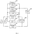
- the embodiment of the present disclosure relates to a pre-charging circuit for the high voltage battery pack, as shown in FIG. 1 , the pre-charging circuit comprises: a high voltage battery pack 101, a main positive switching module 102, a main positive pre-charging module 103, a charging switching module 104, a charging pre-charging module 105, a main negative switching module 106 and a control module 107.
- the positive electrode of the high voltage battery pack 101 is connected to the first end of the main positive switching module 102 and the first end of the charging switching module 104, respectively, the negative electrode of the high voltage battery pack 101 is connected to the first end of the main negative switching module 106; the second end of the main positive switching module 102 is connected to the main positive connection end 122 of the pre-charging circuit, the second end of the charging switching module 104 is connected to the charging connection end 121 of the pre-charging circuit, and the second end of the main negative switching module 106 is connected to the main negative connection end 123 of the pre-charging circuit.
- the main positive pre-charging module 103 is connected in parallel with the main positive switching module 102, and the charging pre-charging module 105 is connected in parallel with the charging switching module 104.
- the control module 107 controls the charging pre-charging module 105 to be switched on, detects the voltage at the first end of the charging switching module 104 and the voltage at the second end of the charging switching module 104, after determining that the voltage at the first end of the charging switching module 104 and the voltage at the second end of the charging switching module 104 conform with a first constraint relationship, the charging switching module 104 is switched on and the charging pre-charging module 105 is switched off.
- the control module 107 controls the main positive pre-charging module 103 to be switched on, detects the voltage at the first end of the main positive switching module 102 and the voltage at the second end of the main positive switching module 102, after determining that the voltage at the first end of the main positive switching module 102 and the voltage at the second end of the main positive switching module 102 conform with a second constraint relationship, the main positive switching module 102 is switched on and the main positive pre-charging module 103 is switched off.
- control module 107 may control the main negative switching module 106 to be switched on before controlling the charging pre-charging module 105 to be switched on.
- control module 107 may simultaneously switches on the main negative switching module 106 and the charging pre-charging module.
- control module 107 may control the main negative switching module 106 to be switched on after controlling the charging pre-charging module 105 to be switched on.
- control module 107 may control the main negative switching module 106 to be switched on before controlling the main positive switching module 103 to be switched on. Alternatively, the control module 107 may simultaneously switches on the main negative switching module 106 and the main positive switching module 103. Alternatively, the control module may control the main negative switching module 106 to be switched on after controlling the main positive switching module 103 to be switched on.
- the pre-charging circuit for the high voltage battery pack is shown in FIG. 2 , and the pre-charging circuit further comprises a charging module 108 and a discharging module 109; the first end of the charging module 108 is connected to the charging connection end 121, and the second end of the charging module 108 is connected to the main negative connection end 123, the first end of the discharging module 109 is connected to the main positive connection end 122, and the second end of the discharging module 109 is connected to the main negative connection end 123.
- the first end of the main negative switching module 106 is taken as a reference ground.
- the charging pre-charging module 105 comprises a charging pre-charging switch and a first resistor network connected in series.
- the main positive pre-charging module 103 comprises a main positive pre-charging switch and a second resistor network connected in series.
- the first resistor network may be a first resistor and the second resistor network may be a second resistor.
- the pre-charging time of the capacitive component across the charging module may be changed. If the resistance of the first resistor is increased, the current in a branch of the charging pre-charging module 105 is reduced, and the pre-charging time of the capacitive component across the charging module is increased. If the resistance of the first resistor is reduced, the current in the branch of the charging pre-charging module 105 is increased, and the pre-charging time of the capacitive component across the charging module is reduced.
- the pre-charging time of the capacitive component across the discharging module may be changed. If the resistance of the second resistor is increased, the current in a branch of the main positive pre-charging module 103 is reduced, and the pre-charging time of the capacitive component across the discharging module is increased. If the resistance of the second resistor is reduced, the current in the branch of the main positive pre-charging module 103 is increased, and the pre-charging time of the capacitive component across the discharging module is reduced.
- the capacitive component across the charging module may be a capacitor connected between the first end of the charging module and the second end of the charging module
- the capacitive component across the discharging module may be a capacitor connected between the first end of the discharging module and the second end of the discharging module.
- the high voltage battery pack pre-charges the capacitive component across the discharging module through the main positive pre-charging module, reducing the difference between the voltage at the first end of the main positive switching module and the voltage at the second end of the main positive switching module, such that an excessive inrush current will not be generated at the moment when the main positive switching module is switched on, and the influence of excessive surge current on the life and stability of the main positive switching module is avoided.
- the high voltage battery pack pre-charges the capacitive component across the charging module through the charging pre-charging module, reducing the difference between the voltage at the first end of the charging switching module and the voltage at the second end of the charging switching module, such that an excessive inrush current will not be generated at the moment when the charging switching module is switched on, and the influence of excessive surge current on the life and stability of the charging switching module is avoided.
- the first constraint relationship may be that the voltage at the second end of the charging switching module 104 is not less than k times the voltage at the first end of the charging switching module 104, where k is a positive number less than 1.
- the second constraint relationship may be that the voltage at the second end of the main positive switching module 102 is not less than t times the voltage at the first end of the main positive switching module 102, where t is a positive number less than 1.
- the values of k and t may be same or different, and the specific values may be set according to the specific structure of the pre-charging circuit for the high voltage battery pack, the parameters of individual components, etc.
- control logic of the pre-charging circuit for the high voltage battery pack will be illustrated below in conjunction with the specific circuit diagram of the pre-charging circuit for the high voltage battery pack.
- the circuit diagram of the pre-charging circuit for the high voltage battery pack is shown in FIG. 3 .
- V represents the high voltage battery pack
- S1 represents the charging pre-charging switch
- S2 represents the charging switching module
- S3 represents the main positive pre-charging switch
- S4 represents the main positive switching module
- S5 represents the main negative switching module
- R1 represents the first resistor network
- R2 represents a second resistor network.
- U1 represents the voltage at the first end of the main positive switching module and the voltage at the first end of the charging switching module
- U2 represents the voltage at the second end of the main positive switching module
- U3 represents the voltage at the second end of the charging switching module.
- the charging module may be a fast charging socket
- the discharging module may be a power consumption apparatus for vehicle, such as a motor, an air conditioner, an inverter, etc.
- the first constraint relationship is that the voltage at the second end of the charging switching module is 0.8 times the voltage at the first end of the charging switching module
- the second constraint relationship is that the voltage at the first end of the main positive switching module is 0.8 times the voltage at the second end of the main positive switching module.
- the control module switches on S1 and S5, and the high voltage battery pack charges the capacitive component across the charging module.
- the control module performs voltage sampling on U1 and U3, and when U1 and U3 conform with the first constraint relationship, the control module switches on S2 and switches off S1, and the charging module charges the high voltage battery pack.
- the control module switches on S3 and S5, and the high voltage battery pack charges the capacitive component across the discharging module, for example, the X capacitor across the discharging module.
- the control module performs voltage sampling on U1 and U2, and when U1 and U2 conform with the second constraint relationship, the control module switches on S4 and switches off S3, and the high voltage battery discharges through the discharging module.
- the pre-charging circuit for the high voltage battery pack may have other circuit configurations.
- the pre-charging circuit for the high voltage battery pack comprises a high voltage battery pack, a charging switching module, a main positive switching module, a main negative switching module, and a main negative pre-charging module, wherein the positive electrode of the high voltage battery pack is connected to the first end of the main positive switching module and the first end of the charging switching module respectively, the negative electrode of the high voltage battery pack is connected to the first end of the main negative switching module; the second end of the main positive switching module is connected to the first end of the discharging module, the second end of the charging switching module is connected to the first end of the charging module, and the second end of the charging module and the second end of the discharging module are connected to the second end of the main negative switching module, respectively.
- the main negative pre-charging module is connected in parallel with the main negative switching module, and the main negative pre-charging module comprises a main negative pre-charging switch and a third resistor network.
- the circuit diagram of the pre-charging circuit is shown in FIG. 4 .
- V represents the high voltage battery pack
- S2 represents the charging switching module
- S4 represents the main positive switching module
- S5 represents the main negative switching module
- S6 represents the main negative pre-charging switch
- R3 represents the third resistor network.
- the control module firstly controls S6 to be switched on, and after the voltage at the second end of the main negative switching module is 0.8 times the voltage at the first end of the main negative switching module, S5 is switched on and S6 is switched off.
- control module determines if the insulation resistance of the high voltage battery pack conforms with a preset requirement before controlling the main positive pre-charging module to be switched on, or before controlling the charging pre-charging module to be switched on, that is, in the implementation, if the insulation resistance of the high voltage battery pack is within a safe range, so as to ensure the safety of the pre-charging circuit for the high voltage battery pack.
- the safety range of insulation resistance may be set according to specific requirements.
- the pre-charging circuit for the high voltage battery pack further comprises a first current detecting module 111; a second end of the charging switching module is connected to a charging connection end 121 through the first current detecting module 111, and the first current detecting module 111 is connected to the control module 107; the control module 107 reports an over-current fault when determining that the current value detected by the first current detecting module 111 exceeds a first threshold.
- the pre-charging circuit for the high voltage battery pack further comprises a second current detecting module 112.
- a second end of the main positive switching module is connected to the main positive connection end 122 through the second current detecting module 112.
- the second current detecting module 112 is connected to the control module 107.
- the control module 107 reports an over-current fault when determining that the current value detected by the second current detecting module 112 exceeds a second threshold.
- the pre-charging circuit for the high voltage battery pack further comprises a third current detecting module 113; a second end of the main negative switching module is connected to the main negative connection terminal 123 through the third current detecting module 113; the third current detecting module 113 is connected to the control module 107.
- the control module 107 reports an over-current fault when determining that the current value detected by the third current detecting module 113 exceeds the first threshold; during the discharging, the control module 107 reports an over-current fault when determining that the current value detected by the third current detecting module 113 exceeds the second threshold.
- the discharging module comprises N load sub-modules 1091
- the pre-charging circuit for the high voltage battery pack further comprises N fourth current detecting modules 114
- the N load sub-modules 1091 and the N fourth current detecting modules 114 are in one-to-one correspondence.
- a first end of each load sub-modules 1091 is connected to a second end of the corresponding fourth current detecting module 114 through a load switch S7, and a first end of the fourth current detecting module 114 is connected to the main positive connection end 122.
- each load sub-module 1091 is connected to the main negative connection end 123; each fourth current detecting module 114 is connected to the control module 107 respectively (not shown); and during the discharging, the control module 107 reports an over-current fault when determining that the current value detected by the fourth current detecting module 114 exceeds a third threshold; where N is a positive integer.
- control module could detect an over-current fault and thus avoiding the effect of the over-current fault on the high voltage battery pack.
- the first threshold, the second threshold, and the third threshold may be determined according to an operating current, a maximum current value, or other parameters of respective components in the pre-charging circuit for the high voltage battery pack.
- the specific values of the first threshold, the second threshold, and the third threshold are not limited in the present embodiment.
- control module may selectively perform strategies, such as switching off a corresponding switch, reducing power, etc.
- control module may report an over-current fault in time when the current flowing through the branch of any of the main positive switching module, the charging switching module, the main negative switching module and respective load switches is located is too large, such that the control module may take measures in time to prevent the current from being too large and thereby damaging the switching modules in the high voltage battery pack and the circuit.
- first current detecting module, the second current detecting module, the third current detecting module, and the fourth current detecting module may be current sensors, or may be other circuits capable of detecting current, and the types of the current detecting module, the second current detecting module, the third current detecting module, and the fourth current detecting module are not limited in the present embodiment.
- both the current of the charging branch and the current of the discharging branch may be detected when charging and discharging take place simultaneously, thereby obtaining the actual current flowing into the high voltage battery pack.
- each module involved in this embodiment is a logic module, and in practical applications, a logical unit may be implemented by a physical unit, a part of a physical unit, or a combination of multiple physical units.
- the present embodiment does not introduce a unit that is less closely related to the technical problem to be solved by the present disclosure, but it does not mean that there are no other units existing in the present embodiment.
- the present embodiment provides a pre-charging circuit for the high voltage battery pack.
- the high voltage battery pack pre-charges the capacitive component of the charging module through the charging pre-charging module, and the charging switching module is switched on after determining that the voltage at the first end of the charging switching module and the voltage at the second end of the charging switching module conform with the first constraint relationship, thereby reducing the difference between the voltage at the first end of the charging switching module and the voltage at the second end of the charging switching module.
- the high voltage battery pack pre-charges the capacitive component of the charging module through the main positive pre-charging module, and the main positive switching module is switched on after determining that the voltage at the first end of the main positive switching module and the voltage at the second end of the main positive switching module comply with the second constraint relationship, thereby reducing the difference between the voltage at the first end of the main positive switching module and the voltage at the second end of the main positive switching module.
- Another embodiment of the present disclosure relates to a pre-charging circuit for the high voltage battery pack and is further improved on the basis of the embodiment described with reference to FIGS. 1-5 , and the specific improvement is that a main negative pre-charging module is provided for the main negative switching module and the main negative pre-charging module may be used as a backup pre-charging module or a pre-charging circuit for the high voltage battery pack to realize hierarchical pre-charging.
- the pre-charging circuit for the high voltage battery pack further comprises a main negative pre-charging module 110 connected in parallel with the main negative switching module 106.
- the primary negative pre-charging module 110 is used as a backup pre-charging module.
- the pre-charging circuit for the high voltage battery pack performs pre-charging through the main negative pre-charging module 110.
- the pre-charging effect nay be achieved by the main negative pre-charging module when a fault occurs in the main positive pre-charging module or the charging pre-charging module, thereby improving the reliability of the pre-charging circuit for the high voltage battery pack.
- the main negative pre-charging module 110 cooperates with the main positive pre-charging module 103 and the charging pre-charging module 105 respectively, to achieve hierarchical pre-charging in a discharging process and hierarchical pre-charging in a charging process.
- the main negative pre-charging module comprises a main negative pre-charging switch and a third resistor network connected in series
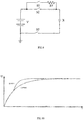
- the circuit diagram of the pre-charging circuit for the high voltage battery pack is shown in FIG. 7 .
- V represents a high voltage battery pack
- S1 represents a charging pre-charging switch
- R1 represents a first resistor network
- S2 represents a charging switching module
- S3 represents a main positive pre-charging switch
- R2 represents a second resistor network
- S4 represents a main positive switch module
- S5 represents a main negative switching module
- S6 represents a main negative pre-charging switch
- R3 represents a third resistor network.
- U1 represents the voltage at the first end of the charging switching module and the voltage at the first end of the main positive switching module
- U2 represents the voltage at the second end of the main positive switching module
- U3 represents the voltage at the second end of the charging switching module
- U4 represents the voltage at the first end of the main negative switching module
- U5 represents the voltage at the second end of the main negative switching module.
- FIG. 8 the simulation diagram of a pre-charging circuit for the high voltage battery pack that does not adopt hierarchical pre-charge is shown in FIG. 9 , and the simulation results of the simulation diagrams shown in FIG. 8 and FIG. 9 are shown in FIG. 10 .
- the pre-charging is mainly performed on a capacitive component across the charging module, as shown in FIG. 8 and FIG. 9 , X represents the capacitive component across the charging module, V represents the high voltage battery pack, S1 represents the charging pre-charging switch, R1 represents a first resistor network, S2 represents the charging switching module, S5 represents the main negative switching module, S6 represents the main negative pre-charging switch, and R3 represents the third resistor network.
- abscissa (t) represents the charging time
- ordinate (U) represents the voltage across X capacitor
- curve 1 is a curve showing the simulation result when adopting hierarchical pre-charging
- curve 2 is a curve showing the simulation result not when hierarchical pre-charging is not adopted.
- the pre-charging time of the charging circuit adopting hierarchical pre-charging is smaller than that of the charging circuit without hierarchical pre-charging.
- S3 and S6 are firstly switched on, and the control module continuously performs voltage sampling on U4 and U5.
- U4 and U5 conforms with the third constraint relationship, for example, when U4 is 0.5 times U5, S5 is switched on and S6 is switched off.
- the control module detects U1 and U2, and when U2 is 0.8 times U1, S4 is switched on and S3 is switched off. At this time, the hierarchical pre-charging is completed.
- the third constraint relationship may be that the voltage at the first end U4 of the main negative switching module is not less than p times the voltage at the second end U5 of the main negative switching module, and p is a positive number less than 1.
- the specific value of p may be set according to the specific structure of the pre-charging circuit for the high voltage battery pack, the parameters of respective components, etc.
- the above-mentioned pre-charging method implemented through the pre-charging circuit for the high voltage battery pack is only an example, and in practical applications, the hierarchical pre-charging may also be implemented by other ways.
- U1 and U3 may be sampled firstly, and after S2 is switched on according to the sampling result, U4 and U5 are then sampled.
- U1 and U2 may be sampled firstly, and after S4 is switched on according to the sampling result, U4 and U5 are then sampled.
- the present embodiment does not limit the specific process of implementing hierarchical pre-charging.
- the first end of the main negative switching module 106 is taken as a reference ground; and when detecting the voltage at the first end of the main negative switching module 106 and the voltage at the second end of the main negative switching module 106, the voltage at the first end of the main positive switching module 102 is taken as a reference ground.
- each module involved in this embodiment is a logic module, and in practical applications, a logical unit may be implemented by a physical unit, a part of a physical unit, or a combination of multiple physical units.
- the present embodiment does not introduce a unit that is less closely related to the technical problem to be solved by the present disclosure, but it does not mean that there are no other units existing in the present embodiment.
- the main negative pre-charging module is connected in parallel with the main negative switching module, such that the main negative pre-charging module may be used as a backup pre-charging module, or may be used to achieve hierarchical pre-charging.
- the main negative pre-charging module is used as a backup pre-charging module, the pre-charging effect may be achieved by the main negative pre-charging module when a fault occurs in the main positive pre-charging module or the charging pre-charging module, thereby improving the reliability of the pre-charging circuit for the high voltage battery pack.
- the main negative pre-charging module cooperates with the main positive pre-charging module and the charging pre-charging module respectively, thereby realizing hierarchical pre-charging and reducing the pre-charging time.
- Yet another embodiment of the present disclosure relates to a pre-charging method for the high voltage battery pack applied to the pre-charging circuit for the high voltage battery pack mentioned in the above embodiment.
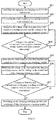
- Step 201 controlling the charging pre-charging module to be switched on.
- control module firstly switches on the main negative switching module and controls the charging pre-charging module to be switched on.
- control module simultaneously switches on the main negative switching module and the charging pre-charging module.
- control module firstly switches on the charging pre-charging module and then switches on the main negative switching module.
- Step 202 detecting the voltage at the first end of the charging switching module and the voltage at the second end of the charging switching module.
- Step 203 determining whether the voltage at the first end of the charging switching module and the voltage at the second end of the charging switching module conform with a first constraint relationship.
- step 204 is performed; otherwise, the process returns to step 202.
- Step 204 switching on the charging switching module and switching off the charging pre-charging module.
- the pre-charging circuit for the high voltage battery pack further comprises a charging module, a first end of the charging module is connected to the charging connection end 121, and the main negative connection end is connected to a second end of the charging module.
- the charging pre-charging module When the charging pre-charging module is switched on, the high voltage battery pack pre-charges a capacitive component across the charging module, and after the charging switching module is switched on, the charging module charges the high voltage battery pack.
- the pre-charging circuit for the high voltage battery pack further comprises a first current detecting module, the second end of the charging switching module is connected to the charging connection end by the first current detecting module, and the first current detecting module is connected to the control module.
- the control module monitors the current of the branch of the charging switching module through the first current detecting module after the charging switching module is switched on and the charging pre-charging module is switched off.
- the control module reports an over-current fault when determining that the current value detected by the first current detecting module exceeds the first threshold.
- control module reduces the current of the branch of the charging switching module by performing strategies, such as switching off the charging switching module or the main negative switching module, reducing power, etc.
- the pre-charging method of the high voltage battery pack is shown in FIG. 12 , the pre-charging method comprises the following steps: Step 301: controlling the main positive pre-charging module to be switched on.
- control module firstly switches on the main negative switching module and then controls the main positive pre-charging module to be switched on.
- the control module simultaneously switches on the main negative switching module and the main positive pre-charging module.
- the control module firstly switches on the main positive pre-charging module and then switches on the main negative switching module.
- Step 302 detecting the voltage at the first end of the main positive switching module and the voltage at the second end of the main positive switching module.
- Step 303 determining whether the voltage at the first end of the main positive switching module and the voltage at the second end of the main positive switching module conform with a second constraint relationship.
- step 304 is performed; otherwise, the process returns to step 302.
- Step 304 switching on the main positive switching module and switching off the main positive pre-charging module.
- the pre-charging circuit for the high voltage battery pack further comprises a discharging module, the main positive connection end is connected to the first end of the discharging module, and the main negative connection end is connected to the second end of the discharging module.
- the high voltage battery pack pre-charges a capacitive component across the discharging module, and after the main positive switching module is switched on, the high voltage battery pack is discharged to the discharging module.
- the pre-charging circuit for the high voltage battery pack further comprises a second current detecting module, the second end of the main positive switching module is connected to the main positive connection terminal through the second current detecting module, and the second current detecting module is connected to the control module.
- the control module monitors the current in the branch of the main positive switching module through the second current detecting module, after the main positive switching module is switched on and the main positive pre-charging module is switched off.
- the control module reports an over-current fault when determining that the current value detected by the second current detecting module exceeds the second threshold.
- the pre-charging circuit for the high voltage battery pack further comprises a third current detecting module, the second end of the main negative switching module is connected to the main negative connection end through the third current detecting module; and the third current detecting module is connected to the control module .
- the control module reports an over-current fault when determining that the current value detected by the third current detecting module exceeds the first threshold;
- the pre-charging method further comprises: reporting an over-current fault when determining that the current value detected by the third current detecting module exceeds the second threshold.
- control module reduces the current in the branch of the main positive switching module by performing strategies, such as switching off the main positive switching module or the main negative switching module, reducing power, etc.
- the discharging module comprises N load sub-modules
- the pre-charging circuit for the high voltage battery pack further comprises N fourth current detecting modules
- the N load sub-modules are in one-to-one correspondence with the N fourth current detecting modules; a first end of each of the load sub-modules is connected to a second end of a corresponding fourth current detecting module through a load switch, a first end of each of the fourth current detecting modules is connected to the main positive connection end, a second end of each of the load sub-modules is connected to the main negative connection end; each of the fourth current detecting modules is connected to the control module.
- the control module monitors the current in the branch of each of load sub-modules is located through the fourth current detecting module after controlling the main positive switching module to be switched on and the main positive pre-charging module to be switched off, and reports an over-current fault when determining that a current value detected by the fourth current detecting module exceeds a third threshold.
- the number of current detecting modules can be determined according to the number of switches in the pre-charging circuit for the high voltage battery pack.
- a current detecting module may be provided in the branch of each switch, or be provided in branches of some switches. The present embodiment does not limit the number and position of the current detecting module.
- control module determines that the insulation resistance of the high voltage battery pack conforms with a preset requirement before controlling the charging pre-charging module to be switched on.
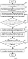
- FIG. 13 a schematic diagram of the overall strategy of the pre-charging method for the high voltage battery pack is shown in FIG. 13 , and the method comprises the following steps:
- step 3013 if the insulation resistance conforms with the preset requirement, step 3013 is performed, otherwise, step 3014 is performed.
- the preset requirement may be set as needed.
- the preset requirement is that the insulation resistance is greater than a fifth preset value.
- Step 3013 performing charging or a discharging.
- steps 201 to 204 are performed. If the discharge process is performed currently, after the insulation resistance value conforms withs the preset requirement, steps 301 to 304 are performed.
- Step 3014 reporting an insulation fault.
- the present embodiment is a method embodiment corresponding to the embodiment described with reference to FIGS. 1-5 , and the present embodiment can be implemented in cooperation with the embodiment described with reference to FIGS. 1-5 .
- the related technical details mentioned in the embodiment described with reference to FIGS. 1-5 still work in the present embodiment, and are not described herein again for conciseness.
- the related technical details mentioned in the present embodiment may also be applied to the embodiment described with reference to FIGS. 1-5 .
- Still another embodiment of the present disclosure relates to a pre-charging method for the high voltage battery pack and it is a further improvement made based on the embodiment described with reference to FIGS. 11-13 , the specific improvement is that the hierarchical pre-charging during the charging process is achieved by controlling the sequences of switching on and switching off the charging switching module, the charging pre-charging module, the main negative switching module, and the main negative pre-charging module; and the hierarchical pre-charging during the discharging process is achieved by controlling the sequences of switching on and switching off the main positive switching module, the main positive pre-charging module, the main positive switching module, and the main negative pre-charging module.
- the pre-charging method for the high voltage battery pack of the present embodiment comprises steps 401 to 408, wherein steps 401, 406 to 408 are substantially the same as steps 201 to 204 of the embodiment described with reference to FIGS. 11-13 , respectively, which will not be described in detail herein. The following are the differences:
- step 401 is presented as a previous step of step 402 for clear description.
- step 402 and step 401 may be performed simultaneously, or step 402 may be performed firstly and then step 401 is performed, and the sequence of steps 401 and 402 is not limited in the present embodiment.
- Step 403 detecting the voltage at the first end of the main negative switching module and the voltage at the second end of the main negative switching module.
- Step 404 determining whether the voltage at the first end of the main negative switching module and the voltage at the second end of the main negative switching module conform with the third constraint relationship.
- step 405 is performed; otherwise, the process returns to step 403.
- Step 405 switching on the main negative switching module and switching off the main negative pre-charging module.
- Step 406 detecting the voltage at the first end of the charging switching module and the voltage at the second end of the charging switching module.
- Step 407 determining whether the voltage at the first end of the charging switching module and the voltage at the second end of the charging switching module conform with the second constraint relationship.
- step 408 is performed; otherwise, step 406 is performed again.
- Step 408 switching on the charging switching module and switching off the charging pre-charging module.
- the control module achieves the hierarchical pre-charging during the charging process by performing steps 401 to 408.
- the pre-charging method for the high voltage battery pack of the present embodiment comprises steps 501 to 508, the steps 501, 506 to 508 are substantially the same as the steps 301 to 304 of the embodiment described with reference to FIGS. 11-13 , respectively, which will not be described in detail herein. The following are the differences:
- step 501 is presented as a previous step of step 502 for clear description2.
- step 502 and step 501 may be performed simultaneously, or step 502 may be performed firstly and then step 501 is performed, and the sequence of steps 501 and 502 is not limited in the present embodiment.
- Step 503 detecting the voltage at the first end of the main negative switching module and the voltage at the second end of the main negative switching module.
- Step 504 determining whether the voltage at the first end of the main negative switching module and the voltage at the second end of the main negative switching module conform with the third constraint relationship.
- step 505 is performed; otherwise, the process returns to step 503.
- Step 505 switching on the main negative switching module and switching off the main negative pre-charging module.
- Step 506 detecting the voltage at the first end of the main positive switching module and the voltage at the second end of the main positive switching module.
- Step 507 determining whether the voltage at the first end of the main positive switching module and the voltage at the second end of the main positive switching module conform with the second constraint relationship.
- step 508 is performed; otherwise, step 506 is performed again.
- Step 508 switching on the main positive switching module and switching off the main positive pre-charging module.
- the voltage across the main negative switching module is detected first, and the main negative switching module is controlled to be switched on according to the detection result, and then the voltage across the charging switching module is detected, and the charging switching module is controlled to be switched on according to the detection result, so as achieve the hierarchical pre-charging.
- the hierarchical pre-charging in the charging process can be realized in other ways.
- the control module firstly controls the main negative pre-charging module and the charging pre-charging module to be switched on, and detects the voltage at the first end of the charging switching module and the voltage at the second end of the charging switching module; determines if the voltage at the first end of the charging switching module and the voltage at the second end of the charging switching module conform with the first constraint relationship; if so, the charging switching module is switched on, and the charging pre-charging module is switched off.
- the control module detects the voltage at the first end of the main negative switching module and the voltage at the second end of the main negative switching module after the charging switching module is switched on and the charging pre-charging module is switched off; determines if the voltage at the first end of the main negative switching module and the voltage at the second end of the main negative switching module conform with the third constraint relationship; if so, the main negative switching module is switched on, and the main negative pre-charging module is switched off.
- the sequence of controlling the main negative switching module and the charging switching module when implementing the hierarchical pre-charging during the charging process is not limited in the present embodiment.
- the voltage across the main negative switching module is detected first, and the main negative switching module is controlled to be switched on according to the detection result, and then the voltage across the main positive switching module is detected, and the main positive switch is controlled to be switched on according to the detection result, so as to achieve the hierarchical pre-charging.
- the hierarchical pre-charging in the discharging process may be realized in other ways.
- the control module firstly controls the main negative pre-charging module and the main positive pre-charging module to be switched on, and detects the voltage at the first end of the main positive switching module and the voltage at the second end of the main positive switching module; determines if the voltage at the first end of the main positive switching module and the voltage at the second end of the main positive switching module conform with the second constraint relationship; if so, the main positive switching module is switched on, and the main positive pre-charging module is switched off.
- the control module detects the voltage at the first end of the main negative switching module and the voltage at the second end of the main negative switching module after the main positive switching module is switched on and the main positive pre-charging module is switched off; determines if the voltage at the first end of the main negative switching module and the voltage at the second end of the main negative switching module conform with the third constraint relationship; if so, the main negative switching module is switched on, and the main negative pre-charging module is switched off.
- the sequence of controlling the main negative switching module and the charging switching module when implementing the hierarchical pre-charging during the discharging process is not limited in the present embodiment.
- the present embodiment is a method embodiment corresponding to the embodiment described with reference to FIGS. 6-10 , and the present embodiment can be implemented in cooperation with the embodiment described with reference to FIGS. 6-10 .
- the related technical details mentioned in the embodiment described with reference to FIGS. 6-10 still work in the present embodiment, and are not described herein again for conciseness.
- the related technical details mentioned in the present embodiment may also be applied to the embodiment described with reference to FIGS. 6-10 .
Landscapes
- Engineering & Computer Science (AREA)
- Power Engineering (AREA)
- General Engineering & Computer Science (AREA)
- Theoretical Computer Science (AREA)
- Computer Hardware Design (AREA)
- Physics & Mathematics (AREA)
- General Physics & Mathematics (AREA)
- Charge And Discharge Circuits For Batteries Or The Like (AREA)
- Secondary Cells (AREA)
Applications Claiming Priority (1)
| Application Number | Priority Date | Filing Date | Title |
|---|---|---|---|
| CN201910064176.6A CN109818393B (zh) | 2019-01-23 | 2019-01-23 | 一种高压电池组的预充电路和预充方法 |
Publications (2)
| Publication Number | Publication Date |
|---|---|
| EP3687025A1 true EP3687025A1 (de) | 2020-07-29 |
| EP3687025B1 EP3687025B1 (de) | 2021-07-21 |
Family
ID=66604871
Family Applications (1)
| Application Number | Title | Priority Date | Filing Date |
|---|---|---|---|
| EP19200314.3A Active EP3687025B1 (de) | 2019-01-23 | 2019-09-29 | Vorladeschaltung und vorladeverfahren für hochspannungsbatteriepack |
Country Status (4)
| Country | Link |
|---|---|
| US (1) | US11404894B2 (de) |
| EP (1) | EP3687025B1 (de) |
| CN (1) | CN109818393B (de) |
| WO (1) | WO2020151601A1 (de) |
Cited By (3)
| Publication number | Priority date | Publication date | Assignee | Title |
|---|---|---|---|---|
| EP4015287A1 (de) * | 2020-12-21 | 2022-06-22 | Volvo Truck Corporation | Ladesystem für einen energiespeicher in einem fahrzeug und verfahren zur steuerung des ladesystems |
| US12176748B2 (en) | 2020-12-21 | 2024-12-24 | Volvo Truck Corporation | Charging system for an energy storage in a vehicle and a method for controlling the charging system |
| US12301046B2 (en) | 2020-12-21 | 2025-05-13 | Volvo Truck Corporation | Charging system for a vehicle and a method for controlling the charging system |
Families Citing this family (31)
| Publication number | Priority date | Publication date | Assignee | Title |
|---|---|---|---|---|
| CN109818393B (zh) * | 2019-01-23 | 2020-05-19 | 宁德时代新能源科技股份有限公司 | 一种高压电池组的预充电路和预充方法 |
| CN112398183B (zh) * | 2019-08-15 | 2023-04-07 | 比亚迪股份有限公司 | 预充电路、能量转换装置及车辆 |
| US20210249872A1 (en) * | 2020-02-06 | 2021-08-12 | Samsung Sdi Co., Ltd. | Battery system |
| CN111555382A (zh) * | 2020-04-17 | 2020-08-18 | 北汽福田汽车股份有限公司 | 一种电池系统及电池系统的控制方法、车辆 |
| US11245268B1 (en) | 2020-07-24 | 2022-02-08 | Inventus Power, Inc. | Mode-based disabling of communiction bus of a battery management system |
| US12224603B2 (en) | 2020-06-02 | 2025-02-11 | Inventus Power, Inc. | Mode-based disabling of communication bus of a battery management system |
| US11588334B2 (en) | 2020-06-02 | 2023-02-21 | Inventus Power, Inc. | Broadcast of discharge current based on state-of-health imbalance between battery packs |
| US11509144B2 (en) | 2020-06-02 | 2022-11-22 | Inventus Power, Inc. | Large-format battery management system with in-rush current protection for master-slave battery packs |
| US11594892B2 (en) | 2020-06-02 | 2023-02-28 | Inventus Power, Inc. | Battery pack with series or parallel identification signal |
| WO2021243550A1 (en) | 2020-06-02 | 2021-12-09 | Inventus Power, Inc. | Large-format battery management system |
| US12301031B1 (en) | 2020-06-02 | 2025-05-13 | Inventus Power, Inc. | Large-format battery management systems with gateway PCBA |
| KR20220035787A (ko) * | 2020-09-14 | 2022-03-22 | 주식회사 엘지에너지솔루션 | 프리차지 저항 이상 판단 방법 및 이를 적용한 배터리 시스템 |
| CN112092629B (zh) * | 2020-09-18 | 2022-05-13 | 广州小鹏汽车科技有限公司 | 高压配电盒、电池系统和高压配电盒的控制方法 |
| KR102722929B1 (ko) * | 2020-10-06 | 2024-10-25 | 주식회사 엘지에너지솔루션 | 배터리 팩, 배터리 시스템 및 프리차지 방법 |
| KR20220055366A (ko) * | 2020-10-26 | 2022-05-03 | 주식회사 엘지에너지솔루션 | 충전 관리 장치, 충전 관리 방법 및 전기 차량 |
| CN112491260A (zh) * | 2020-11-25 | 2021-03-12 | 珠海格力电器股份有限公司 | 一种充电保护电路、方法及开关电源 |
| US11945326B2 (en) * | 2020-12-18 | 2024-04-02 | Preh Gmba | Method and charging device for charging a high-voltage battery of an electric vehicle |
| CN113071315B (zh) * | 2021-03-10 | 2022-10-11 | 重庆长安汽车股份有限公司 | 电动汽车高压电气系统连接完整性检测方法及系统 |
| ES2960182T3 (es) * | 2021-03-10 | 2024-03-01 | Jiangsu Contemporary Amperex Tech Ltd | Circuito de protección, lazo de alto voltaje, aparato eléctrico, método de control, dispositivo y medio |
| EP4070982A1 (de) * | 2021-04-08 | 2022-10-12 | Nxp B.V. | Systeme und verfahren zur erhöhung der verfügbarkeit von herabgesetztem drehmoment |
| CN113561780B (zh) * | 2021-09-03 | 2023-05-12 | 广州小鹏汽车科技有限公司 | 一种高压配电系统、高压配电系统的控制方法和车辆 |
| CN113635767A (zh) * | 2021-09-03 | 2021-11-12 | 广州小鹏汽车科技有限公司 | 一种高压配电系统、高压配电系统的控制方法和车辆 |
| CN113868170B (zh) * | 2021-09-08 | 2024-04-26 | 维沃移动通信有限公司 | 处理器、阻抗调节方法及电子设备 |
| US20250015613A1 (en) * | 2021-11-19 | 2025-01-09 | Inventus Power, Inc. | Large-Format Battery Management System with In-Rush Protection |
| CN114267217A (zh) * | 2021-12-03 | 2022-04-01 | 北京百通科信机械设备有限公司 | 一种电动车电池实训装置和系统 |
| CN116449737A (zh) * | 2022-01-10 | 2023-07-18 | 上海桔晟科技有限公司 | 下电控制电路和下电控制电路的控制方法 |
| CN115123013B (zh) * | 2022-08-03 | 2025-06-24 | 东软睿驰汽车技术(沈阳)有限公司 | 继电器的上电控制方法、装置、电子设备和可读存储介质 |
| CN115133627A (zh) * | 2022-08-24 | 2022-09-30 | 小米汽车科技有限公司 | 充放电电路结构、集成配电单元、动力电池包及车辆 |
| CN220391004U (zh) * | 2023-06-28 | 2024-01-26 | 宁德时代新能源科技股份有限公司 | 电池高压盒、电池包及车辆 |
| CN118596863B (zh) * | 2024-08-08 | 2024-11-19 | 比亚迪股份有限公司 | 可切换电阻网络、电路、系统、方法、装置、介质、产品及车辆 |
| CN119135023A (zh) * | 2024-11-12 | 2024-12-13 | 珠海格力电器股份有限公司 | 一种电机控制系统及其保护装置和控制方法 |
Citations (3)
| Publication number | Priority date | Publication date | Assignee | Title |
|---|---|---|---|---|
| WO2015019144A2 (en) * | 2013-08-09 | 2015-02-12 | Toyota Jidosha Kabushiki Kaisha | Vehicle and method for controlling the vehicle |
| JP2017184333A (ja) * | 2016-03-28 | 2017-10-05 | 住友重機械工業株式会社 | 突入電流低減回路 |
| CN108248390A (zh) * | 2018-01-15 | 2018-07-06 | 浙江吉利汽车研究院有限公司 | 一种高压电池放电电路及其控制方法 |
Family Cites Families (29)
| Publication number | Priority date | Publication date | Assignee | Title |
|---|---|---|---|---|
| JP4874632B2 (ja) * | 2005-11-15 | 2012-02-15 | プライムアースEvエナジー株式会社 | 電池パック |
| CN102549877B (zh) * | 2009-11-11 | 2015-11-25 | 美商源捷有限公司 | 多电池组的联锁机制 |
| FR2959357B1 (fr) * | 2010-04-27 | 2017-08-11 | Denso Corp | Dispositif d'alimentation electrique pour vehicule |
| KR20130049880A (ko) * | 2011-11-07 | 2013-05-15 | 삼성에스디아이 주식회사 | 배터리 팩 및 이의 제어 방법 |
| US9350187B2 (en) * | 2012-01-09 | 2016-05-24 | Johnson Controls Technology Llc | Pre-charging vehicle bus using parallel battery packs |
| JP5787176B2 (ja) * | 2012-04-05 | 2015-09-30 | 株式会社デンソー | 車両の電源制御装置 |
| US9266433B2 (en) * | 2012-07-23 | 2016-02-23 | Ford Global Technologies, Llc | Low cost charger circuit with precharge |
| JP5803965B2 (ja) * | 2013-03-25 | 2015-11-04 | トヨタ自動車株式会社 | 車両 |
| DE102013008586A1 (de) * | 2013-05-17 | 2014-11-20 | Audi Ag | Vorladen eines Kraftfahrzeug-Hochvoltnetzes |
| US9925933B2 (en) * | 2013-08-30 | 2018-03-27 | Ford Global Technologies, Llc | Pre-charge quick key cycling protection |
| US9802558B2 (en) * | 2013-09-27 | 2017-10-31 | GM Global Technology Operations LLC | Distributed vehicle battery high-voltage bus systems and methods |
| CN104901355A (zh) | 2015-04-14 | 2015-09-09 | 北汽福田汽车股份有限公司 | 一种电动汽车预充电装置及方法 |
| JP6041031B1 (ja) * | 2015-10-02 | 2016-12-07 | ミツミ電機株式会社 | 二次電池保護集積回路、二次電池保護装置及び電池パック |
| JP6508005B2 (ja) * | 2015-11-10 | 2019-05-08 | トヨタ自動車株式会社 | 電源装置 |
| JP6308225B2 (ja) * | 2016-01-13 | 2018-04-11 | トヨタ自動車株式会社 | 車載電源システム |
| CN106143346B (zh) | 2016-04-22 | 2019-03-26 | 恒大法拉第未来智能汽车(广东)有限公司 | 车辆及其用于车辆的开关系统 |
| CN107482741B (zh) | 2016-06-13 | 2019-09-20 | 宝沃汽车(中国)有限公司 | 充电控制方法与系统 |
| JP6493353B2 (ja) * | 2016-10-13 | 2019-04-03 | トヨタ自動車株式会社 | 電力供給システム |
| CN206211584U (zh) | 2016-11-07 | 2017-05-31 | 东南(福建)汽车工业有限公司 | 一种电动汽车快速充电安全保护电路 |
| CN207117205U (zh) * | 2017-04-24 | 2018-03-16 | 深圳市道通智能航空技术有限公司 | 多串电池组管理系统 |
| CN107482260A (zh) | 2017-05-27 | 2017-12-15 | 宝沃汽车(中国)有限公司 | 电池系统的加热继电器故障检测方法、装置、系统及车辆 |
| CN207117237U (zh) * | 2017-07-31 | 2018-03-16 | 惠州市蓝微新源技术有限公司 | 一种电池组的软启动电路 |
| CN107452995B (zh) * | 2017-08-21 | 2020-01-31 | 上海空间电源研究所 | 基于can总线的空间高压蓄电池组信息管理总线组网系统 |
| CN107528368A (zh) * | 2017-08-31 | 2017-12-29 | 惠州市蓝微新源技术有限公司 | 一种电池组放电控制电路 |
| CN107571739A (zh) | 2017-09-27 | 2018-01-12 | 风度(常州)汽车研发院有限公司 | 预充电装置、系统及方法 |
| CN107585058A (zh) | 2017-09-29 | 2018-01-16 | 北京新能源汽车股份有限公司 | 一种充电装置及电动汽车 |
| CN207925612U (zh) | 2018-01-18 | 2018-09-28 | 宁波吉利汽车研究开发有限公司 | 一种分布式电池管理系统 |
| CN108808819B (zh) * | 2018-07-17 | 2023-06-23 | 深圳昱泽新能源有限公司 | 一种锂电储能备电系统 |
| CN109818393B (zh) | 2019-01-23 | 2020-05-19 | 宁德时代新能源科技股份有限公司 | 一种高压电池组的预充电路和预充方法 |
-
2019
- 2019-01-23 CN CN201910064176.6A patent/CN109818393B/zh active Active
- 2019-09-29 EP EP19200314.3A patent/EP3687025B1/de active Active
- 2019-09-30 US US16/587,126 patent/US11404894B2/en active Active
-
2020
- 2020-01-17 WO PCT/CN2020/072855 patent/WO2020151601A1/zh not_active Ceased
Patent Citations (3)
| Publication number | Priority date | Publication date | Assignee | Title |
|---|---|---|---|---|
| WO2015019144A2 (en) * | 2013-08-09 | 2015-02-12 | Toyota Jidosha Kabushiki Kaisha | Vehicle and method for controlling the vehicle |
| JP2017184333A (ja) * | 2016-03-28 | 2017-10-05 | 住友重機械工業株式会社 | 突入電流低減回路 |
| CN108248390A (zh) * | 2018-01-15 | 2018-07-06 | 浙江吉利汽车研究院有限公司 | 一种高压电池放电电路及其控制方法 |
Cited By (4)
| Publication number | Priority date | Publication date | Assignee | Title |
|---|---|---|---|---|
| EP4015287A1 (de) * | 2020-12-21 | 2022-06-22 | Volvo Truck Corporation | Ladesystem für einen energiespeicher in einem fahrzeug und verfahren zur steuerung des ladesystems |
| US12176748B2 (en) | 2020-12-21 | 2024-12-24 | Volvo Truck Corporation | Charging system for an energy storage in a vehicle and a method for controlling the charging system |
| US12301046B2 (en) | 2020-12-21 | 2025-05-13 | Volvo Truck Corporation | Charging system for a vehicle and a method for controlling the charging system |
| US12381411B2 (en) | 2020-12-21 | 2025-08-05 | Volvo Truck Corporation | Charging system for an energy storage in a vehicle and a method for controlling the charging system |
Also Published As
| Publication number | Publication date |
|---|---|
| US11404894B2 (en) | 2022-08-02 |
| CN109818393A (zh) | 2019-05-28 |
| EP3687025B1 (de) | 2021-07-21 |
| US20200235586A1 (en) | 2020-07-23 |
| CN109818393B (zh) | 2020-05-19 |
| WO2020151601A1 (zh) | 2020-07-30 |
Similar Documents
| Publication | Publication Date | Title |
|---|---|---|
| EP3687025B1 (de) | Vorladeschaltung und vorladeverfahren für hochspannungsbatteriepack | |
| US11942775B2 (en) | High voltage battery cluster, and overcurrent protection circuit and switch box thereof | |
| AU2021255319B2 (en) | Protection device and protection method for photovoltaic power generation system, and photovoltaic power generation system | |
| CN106809037B (zh) | 轨道车辆控制系统及轨道车辆 | |
| JP5386185B2 (ja) | 電力変換装置 | |
| CN112615358B (zh) | 一种船舶直流组网电力推进系统及短路故障快速保护方法 | |
| CN103646805B (zh) | 一种直流断路器拓扑 | |
| CN103269166A (zh) | 具有预充电保护功能的变频器 | |
| CN102055176A (zh) | 一种用于保护电动汽车接触器的方法及电池管理系统 | |
| EP2795758A1 (de) | Anordnung zur steuerung der stromübertragung in einem hvdc-stromübertragungssystem | |
| CN107017673A (zh) | 电压断开结构 | |
| CN115102135B (zh) | 一种基于晶闸管的低损耗双向直流固态断路器及其控制方法 | |
| CN111965515A (zh) | 一种防反灌二极管故障识别方法 | |
| Sakuraba et al. | Evaluation of novel hybrid protection based on pyroswitch and fuse technologies | |
| CN212708991U (zh) | 一种带预充和放电功能的车载充电器 | |
| CN208842232U (zh) | 电池管理系统中保护预充继电器的控制电路 | |
| CN109066605B (zh) | 直流输电系统正负极直流断路器的协调动作控制策略 | |
| CN103378588A (zh) | 一种新能源汽车高压电器盒 | |
| CN103944149B (zh) | 一种蓄电池馈电保护电路 | |
| CN106712152B (zh) | 一种电动车动力电池的功率分配方法、装置及电动车 | |
| CN108336717A (zh) | 一种适用于调相机变压器组启机过程全区域的启机保护方法 | |
| JP2026504967A (ja) | 大電力周期的負荷のためのハイブリッド異常保護回路 | |
| CN204316118U (zh) | 充放电设备 | |
| CN110165641B (zh) | 柔性直流输电系统中直流断路器的重合方法 | |
| CN113964806A (zh) | 电气防火限流式短路保护方法 |
Legal Events
| Date | Code | Title | Description |
|---|---|---|---|
| PUAI | Public reference made under article 153(3) epc to a published international application that has entered the european phase |
Free format text: ORIGINAL CODE: 0009012 |
|
| STAA | Information on the status of an ep patent application or granted ep patent |
Free format text: STATUS: REQUEST FOR EXAMINATION WAS MADE |
|
| 17P | Request for examination filed |
Effective date: 20191018 |
|
| AK | Designated contracting states |
Kind code of ref document: A1 Designated state(s): AL AT BE BG CH CY CZ DE DK EE ES FI FR GB GR HR HU IE IS IT LI LT LU LV MC MK MT NL NO PL PT RO RS SE SI SK SM TR |
|
| AX | Request for extension of the european patent |
Extension state: BA ME |
|
| STAA | Information on the status of an ep patent application or granted ep patent |
Free format text: STATUS: EXAMINATION IS IN PROGRESS |
|
| 17Q | First examination report despatched |
Effective date: 20201216 |
|
| GRAP | Despatch of communication of intention to grant a patent |
Free format text: ORIGINAL CODE: EPIDOSNIGR1 |
|
| STAA | Information on the status of an ep patent application or granted ep patent |
Free format text: STATUS: GRANT OF PATENT IS INTENDED |
|
| INTG | Intention to grant announced |
Effective date: 20210506 |
|
| GRAS | Grant fee paid |
Free format text: ORIGINAL CODE: EPIDOSNIGR3 |
|
| GRAA | (expected) grant |
Free format text: ORIGINAL CODE: 0009210 |
|
| STAA | Information on the status of an ep patent application or granted ep patent |
Free format text: STATUS: THE PATENT HAS BEEN GRANTED |
|
| AK | Designated contracting states |
Kind code of ref document: B1 Designated state(s): AL AT BE BG CH CY CZ DE DK EE ES FI FR GB GR HR HU IE IS IT LI LT LU LV MC MK MT NL NO PL PT RO RS SE SI SK SM TR |
|
| REG | Reference to a national code |
Ref country code: GB Ref legal event code: FG4D |
|
| REG | Reference to a national code |
Ref country code: CH Ref legal event code: EP |
|
| REG | Reference to a national code |
Ref country code: DE Ref legal event code: R096 Ref document number: 602019006242 Country of ref document: DE |
|
| REG | Reference to a national code |
Ref country code: AT Ref legal event code: REF Ref document number: 1413500 Country of ref document: AT Kind code of ref document: T Effective date: 20210815 |
|
| REG | Reference to a national code |
Ref country code: IE Ref legal event code: FG4D |
|
| REG | Reference to a national code |
Ref country code: LT Ref legal event code: MG9D |
|
| REG | Reference to a national code |
Ref country code: NL Ref legal event code: MP Effective date: 20210721 |
|
| REG | Reference to a national code |
Ref country code: AT Ref legal event code: MK05 Ref document number: 1413500 Country of ref document: AT Kind code of ref document: T Effective date: 20210721 |
|
| PG25 | Lapsed in a contracting state [announced via postgrant information from national office to epo] |
Ref country code: LT Free format text: LAPSE BECAUSE OF FAILURE TO SUBMIT A TRANSLATION OF THE DESCRIPTION OR TO PAY THE FEE WITHIN THE PRESCRIBED TIME-LIMIT Effective date: 20210721 Ref country code: AT Free format text: LAPSE BECAUSE OF FAILURE TO SUBMIT A TRANSLATION OF THE DESCRIPTION OR TO PAY THE FEE WITHIN THE PRESCRIBED TIME-LIMIT Effective date: 20210721 Ref country code: BG Free format text: LAPSE BECAUSE OF FAILURE TO SUBMIT A TRANSLATION OF THE DESCRIPTION OR TO PAY THE FEE WITHIN THE PRESCRIBED TIME-LIMIT Effective date: 20211021 Ref country code: HR Free format text: LAPSE BECAUSE OF FAILURE TO SUBMIT A TRANSLATION OF THE DESCRIPTION OR TO PAY THE FEE WITHIN THE PRESCRIBED TIME-LIMIT Effective date: 20210721 Ref country code: NO Free format text: LAPSE BECAUSE OF FAILURE TO SUBMIT A TRANSLATION OF THE DESCRIPTION OR TO PAY THE FEE WITHIN THE PRESCRIBED TIME-LIMIT Effective date: 20211021 Ref country code: NL Free format text: LAPSE BECAUSE OF FAILURE TO SUBMIT A TRANSLATION OF THE DESCRIPTION OR TO PAY THE FEE WITHIN THE PRESCRIBED TIME-LIMIT Effective date: 20210721 Ref country code: PT Free format text: LAPSE BECAUSE OF FAILURE TO SUBMIT A TRANSLATION OF THE DESCRIPTION OR TO PAY THE FEE WITHIN THE PRESCRIBED TIME-LIMIT Effective date: 20211122 Ref country code: SE Free format text: LAPSE BECAUSE OF FAILURE TO SUBMIT A TRANSLATION OF THE DESCRIPTION OR TO PAY THE FEE WITHIN THE PRESCRIBED TIME-LIMIT Effective date: 20210721 Ref country code: RS Free format text: LAPSE BECAUSE OF FAILURE TO SUBMIT A TRANSLATION OF THE DESCRIPTION OR TO PAY THE FEE WITHIN THE PRESCRIBED TIME-LIMIT Effective date: 20210721 Ref country code: FI Free format text: LAPSE BECAUSE OF FAILURE TO SUBMIT A TRANSLATION OF THE DESCRIPTION OR TO PAY THE FEE WITHIN THE PRESCRIBED TIME-LIMIT Effective date: 20210721 Ref country code: ES Free format text: LAPSE BECAUSE OF FAILURE TO SUBMIT A TRANSLATION OF THE DESCRIPTION OR TO PAY THE FEE WITHIN THE PRESCRIBED TIME-LIMIT Effective date: 20210721 |
|
| PG25 | Lapsed in a contracting state [announced via postgrant information from national office to epo] |
Ref country code: PL Free format text: LAPSE BECAUSE OF FAILURE TO SUBMIT A TRANSLATION OF THE DESCRIPTION OR TO PAY THE FEE WITHIN THE PRESCRIBED TIME-LIMIT Effective date: 20210721 Ref country code: LV Free format text: LAPSE BECAUSE OF FAILURE TO SUBMIT A TRANSLATION OF THE DESCRIPTION OR TO PAY THE FEE WITHIN THE PRESCRIBED TIME-LIMIT Effective date: 20210721 Ref country code: GR Free format text: LAPSE BECAUSE OF FAILURE TO SUBMIT A TRANSLATION OF THE DESCRIPTION OR TO PAY THE FEE WITHIN THE PRESCRIBED TIME-LIMIT Effective date: 20211022 |
|
| REG | Reference to a national code |
Ref country code: DE Ref legal event code: R097 Ref document number: 602019006242 Country of ref document: DE |
|
| PG25 | Lapsed in a contracting state [announced via postgrant information from national office to epo] |
Ref country code: DK Free format text: LAPSE BECAUSE OF FAILURE TO SUBMIT A TRANSLATION OF THE DESCRIPTION OR TO PAY THE FEE WITHIN THE PRESCRIBED TIME-LIMIT Effective date: 20210721 |
|
| REG | Reference to a national code |
Ref country code: BE Ref legal event code: MM Effective date: 20210930 |
|
| PLBE | No opposition filed within time limit |
Free format text: ORIGINAL CODE: 0009261 |
|
| STAA | Information on the status of an ep patent application or granted ep patent |
Free format text: STATUS: NO OPPOSITION FILED WITHIN TIME LIMIT |
|
| PG25 | Lapsed in a contracting state [announced via postgrant information from national office to epo] |
Ref country code: SM Free format text: LAPSE BECAUSE OF FAILURE TO SUBMIT A TRANSLATION OF THE DESCRIPTION OR TO PAY THE FEE WITHIN THE PRESCRIBED TIME-LIMIT Effective date: 20210721 Ref country code: SK Free format text: LAPSE BECAUSE OF FAILURE TO SUBMIT A TRANSLATION OF THE DESCRIPTION OR TO PAY THE FEE WITHIN THE PRESCRIBED TIME-LIMIT Effective date: 20210721 Ref country code: RO Free format text: LAPSE BECAUSE OF FAILURE TO SUBMIT A TRANSLATION OF THE DESCRIPTION OR TO PAY THE FEE WITHIN THE PRESCRIBED TIME-LIMIT Effective date: 20210721 Ref country code: MC Free format text: LAPSE BECAUSE OF FAILURE TO SUBMIT A TRANSLATION OF THE DESCRIPTION OR TO PAY THE FEE WITHIN THE PRESCRIBED TIME-LIMIT Effective date: 20210721 Ref country code: EE Free format text: LAPSE BECAUSE OF FAILURE TO SUBMIT A TRANSLATION OF THE DESCRIPTION OR TO PAY THE FEE WITHIN THE PRESCRIBED TIME-LIMIT Effective date: 20210721 Ref country code: CZ Free format text: LAPSE BECAUSE OF FAILURE TO SUBMIT A TRANSLATION OF THE DESCRIPTION OR TO PAY THE FEE WITHIN THE PRESCRIBED TIME-LIMIT Effective date: 20210721 Ref country code: AL Free format text: LAPSE BECAUSE OF FAILURE TO SUBMIT A TRANSLATION OF THE DESCRIPTION OR TO PAY THE FEE WITHIN THE PRESCRIBED TIME-LIMIT Effective date: 20210721 |
|
| 26N | No opposition filed |
Effective date: 20220422 |
|
| PG25 | Lapsed in a contracting state [announced via postgrant information from national office to epo] |
Ref country code: LU Free format text: LAPSE BECAUSE OF NON-PAYMENT OF DUE FEES Effective date: 20210929 Ref country code: IT Free format text: LAPSE BECAUSE OF FAILURE TO SUBMIT A TRANSLATION OF THE DESCRIPTION OR TO PAY THE FEE WITHIN THE PRESCRIBED TIME-LIMIT Effective date: 20210721 Ref country code: IE Free format text: LAPSE BECAUSE OF NON-PAYMENT OF DUE FEES Effective date: 20210929 Ref country code: BE Free format text: LAPSE BECAUSE OF NON-PAYMENT OF DUE FEES Effective date: 20210930 |
|
| REG | Reference to a national code |
Ref country code: CH Ref legal event code: PL |
|
| P01 | Opt-out of the competence of the unified patent court (upc) registered |
Effective date: 20230516 |
|
| PG25 | Lapsed in a contracting state [announced via postgrant information from national office to epo] |
Ref country code: CY Free format text: LAPSE BECAUSE OF FAILURE TO SUBMIT A TRANSLATION OF THE DESCRIPTION OR TO PAY THE FEE WITHIN THE PRESCRIBED TIME-LIMIT Effective date: 20210721 |
|
| PG25 | Lapsed in a contracting state [announced via postgrant information from national office to epo] |
Ref country code: LI Free format text: LAPSE BECAUSE OF NON-PAYMENT OF DUE FEES Effective date: 20220930 Ref country code: HU Free format text: LAPSE BECAUSE OF FAILURE TO SUBMIT A TRANSLATION OF THE DESCRIPTION OR TO PAY THE FEE WITHIN THE PRESCRIBED TIME-LIMIT; INVALID AB INITIO Effective date: 20190929 Ref country code: CH Free format text: LAPSE BECAUSE OF NON-PAYMENT OF DUE FEES Effective date: 20220930 |
|
| PG25 | Lapsed in a contracting state [announced via postgrant information from national office to epo] |
Ref country code: MK Free format text: LAPSE BECAUSE OF FAILURE TO SUBMIT A TRANSLATION OF THE DESCRIPTION OR TO PAY THE FEE WITHIN THE PRESCRIBED TIME-LIMIT Effective date: 20210721 |
|
| PG25 | Lapsed in a contracting state [announced via postgrant information from national office to epo] |
Ref country code: TR Free format text: LAPSE BECAUSE OF FAILURE TO SUBMIT A TRANSLATION OF THE DESCRIPTION OR TO PAY THE FEE WITHIN THE PRESCRIBED TIME-LIMIT Effective date: 20210721 |
|
| REG | Reference to a national code |
Ref country code: DE Ref legal event code: R081 Ref document number: 602019006242 Country of ref document: DE Owner name: CONTEMPORARY AMPEREX TECHNOLOGY (HONG KONG) LI, HK Free format text: FORMER OWNER: CONTEMPORARY AMPEREX TECHNOLOGY CO., LTD., NINGDE CITY, FUJIAN, CN |
|
| REG | Reference to a national code |
Ref country code: GB Ref legal event code: 732E Free format text: REGISTERED BETWEEN 20240815 AND 20240821 |
|
| PG25 | Lapsed in a contracting state [announced via postgrant information from national office to epo] |
Ref country code: MT Free format text: LAPSE BECAUSE OF FAILURE TO SUBMIT A TRANSLATION OF THE DESCRIPTION OR TO PAY THE FEE WITHIN THE PRESCRIBED TIME-LIMIT Effective date: 20210721 |
|
| PGFP | Annual fee paid to national office [announced via postgrant information from national office to epo] |
Ref country code: DE Payment date: 20250805 Year of fee payment: 7 |
|
| PGFP | Annual fee paid to national office [announced via postgrant information from national office to epo] |
Ref country code: GB Payment date: 20250807 Year of fee payment: 7 |
|
| PGFP | Annual fee paid to national office [announced via postgrant information from national office to epo] |
Ref country code: FR Payment date: 20250808 Year of fee payment: 7 |