EP3687129A1 - Procédé de transmission, dispositif terminal et dispositif de réseau - Google Patents
Procédé de transmission, dispositif terminal et dispositif de réseau Download PDFInfo
- Publication number
- EP3687129A1 EP3687129A1 EP17928419.5A EP17928419A EP3687129A1 EP 3687129 A1 EP3687129 A1 EP 3687129A1 EP 17928419 A EP17928419 A EP 17928419A EP 3687129 A1 EP3687129 A1 EP 3687129A1
- Authority
- EP
- European Patent Office
- Prior art keywords
- message
- terminal device
- network device
- preset time
- secondary carrier
- Prior art date
- Legal status (The legal status is an assumption and is not a legal conclusion. Google has not performed a legal analysis and makes no representation as to the accuracy of the status listed.)
- Pending
Links
- 238000000034 method Methods 0.000 title claims abstract description 55
- 230000005540 biological transmission Effects 0.000 title claims abstract description 19
- 238000012545 processing Methods 0.000 claims description 14
- 230000015654 memory Effects 0.000 description 43
- 238000004891 communication Methods 0.000 description 14
- 230000006870 function Effects 0.000 description 12
- 238000010586 diagram Methods 0.000 description 11
- 230000008569 process Effects 0.000 description 7
- 230000002776 aggregation Effects 0.000 description 4
- 238000004220 aggregation Methods 0.000 description 4
- 238000010295 mobile communication Methods 0.000 description 4
- 230000001360 synchronised effect Effects 0.000 description 4
- 230000004913 activation Effects 0.000 description 3
- 238000004590 computer program Methods 0.000 description 3
- 230000008878 coupling Effects 0.000 description 3
- 238000010168 coupling process Methods 0.000 description 3
- 238000005859 coupling reaction Methods 0.000 description 3
- 230000000977 initiatory effect Effects 0.000 description 2
- 230000007774 longterm Effects 0.000 description 2
- 230000003287 optical effect Effects 0.000 description 2
- 230000003068 static effect Effects 0.000 description 2
- 230000003213 activating effect Effects 0.000 description 1
- 230000001413 cellular effect Effects 0.000 description 1
- 239000003795 chemical substances by application Substances 0.000 description 1
- 238000013500 data storage Methods 0.000 description 1
- 238000013461 design Methods 0.000 description 1
- 239000013307 optical fiber Substances 0.000 description 1
- 239000004065 semiconductor Substances 0.000 description 1
- 239000007787 solid Substances 0.000 description 1
- 238000012360 testing method Methods 0.000 description 1
- 230000001960 triggered effect Effects 0.000 description 1
Images


Classifications
-
- H—ELECTRICITY
- H04—ELECTRIC COMMUNICATION TECHNIQUE
- H04W—WIRELESS COMMUNICATION NETWORKS
- H04W56/00—Synchronisation arrangements
- H04W56/0005—Synchronisation arrangements synchronizing of arrival of multiple uplinks
-
- H—ELECTRICITY
- H04—ELECTRIC COMMUNICATION TECHNIQUE
- H04L—TRANSMISSION OF DIGITAL INFORMATION, e.g. TELEGRAPHIC COMMUNICATION
- H04L27/00—Modulated-carrier systems
- H04L27/26—Systems using multi-frequency codes
-
- H—ELECTRICITY
- H04—ELECTRIC COMMUNICATION TECHNIQUE
- H04W—WIRELESS COMMUNICATION NETWORKS
- H04W72/00—Local resource management
- H04W72/04—Wireless resource allocation
- H04W72/044—Wireless resource allocation based on the type of the allocated resource
- H04W72/0453—Resources in frequency domain, e.g. a carrier in FDMA
-
- H—ELECTRICITY
- H04—ELECTRIC COMMUNICATION TECHNIQUE
- H04W—WIRELESS COMMUNICATION NETWORKS
- H04W72/00—Local resource management
- H04W72/20—Control channels or signalling for resource management
- H04W72/23—Control channels or signalling for resource management in the downlink direction of a wireless link, i.e. towards a terminal
Definitions
- This application relates to the communications field, and more specifically, to a transmission method, a terminal device, and a network device.
- MTA Carrier Aggregation, CA
- MTA-based uplink 2 carrier aggregation has been put into commercial use, for example, South Korea LG U+ has been successfully put into commercial use.
- a plurality of operators are actively testing and preparing, and are ready for commercial use.
- a terminal device After receiving a secondary carrier activation message, a terminal device supports a maximum of 34 ms activation delay.
- This application provides a transmission method, a terminal device, and a network device, to flexibly adjust a time for triggering resynchronization of an uplink secondary carrier cell.
- a transmission method includes: sending, by a terminal device, a second message to a network device after receiving a first message that is sent by the network device and that is used to instruct to activate a secondary carrier cell, where the second message is used to indicate a preset time; and receiving, by the terminal device, a third message that is sent by the network device based on the preset time, where the third message is used to instruct to trigger resynchronization of the secondary carrier cell.
- the third message is a PDCCH order.
- a time for triggering resynchronization of an uplink secondary carrier cell can be flexibly adjusted.
- the method further includes: determining, by the terminal device, the preset time based on a preparation time for demodulating a physical downlink control channel PDCCH by the terminal device.
- the terminal device determines the preset time based on an antenna status of the terminal device.
- the preset time is a time difference between a moment at which the terminal device receives the first message and a moment at which the terminal device receives the third message.
- the second message is a media access control layer control element MCE.
- duration of the preset time is less than or equal to 30 ms.
- the transmission method in this embodiment of this application helps quickly reduce a time for triggering resynchronization of an uplink secondary carrier cell, and improve an uplink throughput.
- a transmission method includes: receiving, by a network device after sending a first message used to instruct to activate a secondary carrier cell, a second message sent by a terminal device, where the second message is used to indicate a preset time; and sending, by the network device, the third message to the terminal device based on the preset time, where the third message is used to instruct to trigger resynchronization of the secondary carrier cell.
- the third message is a PDCCH order.
- a time for triggering resynchronization of an uplink secondary carrier cell can be flexibly adjusted.
- the preset time is a time difference between a moment at which the network device sends the first message and a moment at which the network device sends the third message.
- the second message is a media access control layer control element MCE.
- duration of the preset time is less than or equal to 30 ms.
- the transmission method in this embodiment of this application helps quickly reduce a time for triggering resynchronization of an uplink secondary carrier cell, and improve an uplink throughput.
- a terminal device includes: a transceiver module, configured to send a second message to a network device after receiving a first message that is sent by the network device and that is used to instruct to activate a secondary carrier cell, where the second message is used to indicate a preset time; and a processing module, configured to receive a third message that is sent by the network device based on the preset time, where the third message is used to instruct to trigger resynchronization of the secondary carrier cell.
- the processing module is further configured to determine the preset time based on a preparation time for demodulating a physical downlink control channel PDCCH by the terminal device.
- the preset time is a time difference between a moment at which the transceiver module receives the first message and a moment at which the transceiver module receives the third message.
- the second message is a media access control layer control element MCE.
- duration of the preset time is less than or equal to 30 ms.
- the terminal device in this embodiment of this application may notify the network device of the preset time in advance. This helps quickly reduce a time for triggering resynchronization of an uplink secondary carrier cell, and improve an uplink throughput.
- a network device includes: a transceiver module, configured to: after sending a first message used to instruct to activate a secondary carrier cell, receive a second message sent by a terminal device, where the second message is used to indicate a preset time; and a processing module, configured to send the third message to the terminal device based on the preset time, where the third message is used to instruct to trigger resynchronization of the secondary carrier cell.
- the preset time is a time difference between a moment at which the transceiver module sends the first message and a moment at which the transceiver module sends the third message.
- the second message is a media access control layer control element MCE.
- duration of the preset time is less than or equal to 30 ms.
- the terminal device may notify the network device of the preset time in advance. This helps quickly reduce a time for triggering resynchronization of an uplink secondary carrier cell, and improve an uplink throughput.
- a terminal device includes a memory and a processor.
- the memory is configured to store an instruction
- the processor is configured to invoke the instruction in the memory, to perform operations in the method in the first aspect or any one of the possible implementations of the first aspect.
- a network device includes a memory and a processor.
- the memory is configured to store an instruction
- the processor is configured to invoke the instruction in the memory, to perform operations in the method in the second aspect or any one of the possible implementations of the second aspect.
- a communications system includes a terminal device and/or a network device.
- the terminal device is the terminal device in the third aspect, the fifth aspect, or any one of the possible implementations of the third aspect and the fifth aspect.
- the network device is the network device in the fourth aspect, the sixth aspect, or any one of the possible implementations of the fourth aspect and the sixth aspect.
- a computer-readable storage medium stores an instruction.
- the instruction When the instruction is run on a computer, the computer is enabled to perform the methods according to the foregoing aspects.
- a system chip includes an input/output interface, at least one processor, at least one memory, and a bus.
- the at least one memory is configured to store an instruction
- the at least one processor is configured to invoke the instruction in the at least one memory, to perform operations of the methods in the foregoing aspects.
- GSM Global System of Mobile Communication
- CDMA Code Division Multiple Access
- WCDMA Wideband Code Division Multiple Access
- GPRS General Packet Radio Service
- LTE Long Term Evolution
- FDD Frequency Division Duplex
- TDD Time Division Duplex
- Universal Mobile Telecommunication System Universal Mobile Telecommunication System
- UMTS Universal Mobile Telecommunication System
- a terminal device in the embodiments of this application may be referred to as user equipment, an access terminal, a subscriber unit, a subscriber station, a mobile station, a mobile console, a remote station, a remote terminal, a mobile device, a user terminal, a terminal, a wireless communications device, a user agent, a user apparatus, or the like.
- the terminal device may also be a cellular phone, a cordless phone, a session initiation protocol (Session Initiation Protocol, SIP) phone, a wireless local loop (Wireless Local Loop, WLL) station, a personal digital assistant (Personal Digital Assistant, PDA), a handheld device having a wireless communication function, a computing device, another processing device connected to a wireless modem, a vehicle-mounted device, a wearable device, a terminal device in a future 5G network, a terminal device in a future evolved public land mobile network (Public Land Mobile Network, PLMN), or the like. This is not limited in the embodiments of this application.
- SIP Session Initiation Protocol
- WLL Wireless Local Loop
- PDA Personal Digital Assistant
- a network device in the embodiments of this application may be a device configured to communicate with the terminal device.
- the network device may be a base transceiver station (Base Transceiver Station, BTS) in the global system for mobile communications (Global System of Mobile communication, GSM) or the code division multiple access (Code Division Multiple Access, CDMA) system, or may be a NodeB (NodeB, NB) in the wideband code division multiple access (Wideband Code Division Multiple Access, WCDMA) system, or may be an evolved NodeB (Evolutional NodeB, eNB or eNodeB) in the LTE system, or may be a radio controller in a cloud radio access network (Cloud Radio Access Network, CRAN) scenario.
- BTS Base Transceiver Station
- GSM Global System of Mobile communication
- CDMA Code Division Multiple Access
- NodeB NodeB
- WCDMA Wideband Code Division Multiple Access
- Evolutional NodeB, eNB or eNodeB evolved NodeB
- eNB evolved
- the network device may be a relay node, an access point, a vehicle-mounted device, a wearable device, a network device in the future 5G network, a network device in the future evolved PLMN network, or the like. This is not limited in the embodiments of this application.
- FIG. 1 is an application scenario of a technical solution according to an embodiment of this application.
- the terminal device may report a capability of the terminal device to the network device, for example, a preparation time for demodulating a physical downlink control channel (Physical Downlink Control Channel, PDCCH) by the terminal device.
- PDCCH Physical Downlink Control Channel
- the network device After learning of the capability of the terminal device, the network device sends, based on the capability of the terminal device, a message for triggering resynchronization of the secondary carrier cell to the terminal device.
- PDCCH Physical Downlink Control Channel
- FIG. 2 is a schematic flowchart of a transmission method 100 according to an embodiment of this application. As shown in FIG. 2 , the method 100 includes the following steps.
- a terminal device receives a first message sent by a network device.
- the network device sends the first message to the terminal device, where the first message is used to instruct the terminal device to activate a secondary carrier cell.
- the terminal device After receiving the first message, the terminal device sends a second message to the network device.
- the network device receives the second message sent by the terminal device, where the second message is used to indicate a preset time.
- the network device sends the third message to the terminal device based on the preset time, where the third message is used to instruct the terminal device to trigger resynchronization of the secondary carrier cell.
- the network device when an MTA is enabled, the network device sends the first message to the terminal device, and the first message is used to instruct the terminal device to activate the secondary carrier cell.
- the terminal device After receiving the first message, the terminal device sends the second message to the network device, to report a capability, that is, the preset time, of the terminal device.
- the network device After receiving the second message, the network device sends, based on the preset time that is of the terminal device and that is carried in the second message, the third message to the terminal device, and the third message is used to instruct the terminal device to trigger resynchronization of the secondary carrier cell.
- the preset time is less than or equal to 30 ms. It should be understood that the preset time may be a time period, or may be a moment. This is not limited in this application.
- a current implementation is that a PDCCH order (PDCCH order) is sent after a delay of 30 ms after activation, to trigger SCC resynchronization.
- PDCCH order PDCCH order
- a terminal device with a relatively strong capability does not need to wait for such a long time, and an excessively long waiting time causes a performance loss.
- a time for triggering resynchronization of an uplink secondary carrier cell can be flexibly adjusted.
- the method further includes: determining, by the terminal device, the preset time based on a preparation time for demodulating a physical downlink control channel PDCCH by the terminal device.
- the terminal device activates the uplink SCC, and the terminal device determines the preset time based on the preparation time for demodulating the physical downlink control channel PDCCH by the terminal device.
- the terminal device may determine the preset time based on the preparation time for demodulating the physical downlink control channel PDCCH by the terminal device, or may determine the preset time based on an antenna status of the terminal device, or may determine the preset time based on another condition that is related to the capability of the terminal device. This application is not limited thereto.
- the preset time is a time difference between a moment at which the terminal device receives the first message and a moment at which the terminal device receives the third message.
- the preset time is ⁇ t
- the sending, by the network device, the third message to the terminal device based on the preset time includes: sending, by the network device, the third message to the terminal device after sending the first message and waiting for ⁇ t.
- the terminal device sends the second message to the network device, and the second message carries the preset time ⁇ t. After sending the first message, the network device waits for ⁇ t, and sends the third message to the terminal device.
- the network device determines the preset time in the second message as duration from sending the first message to sending the third message.
- a moment at which the network device sends the first message to the terminal device, a moment at which the terminal device sends the second message to the network device, and a moment at which the network device receives the second message are considered as a same moment, and a delay from sending the first message by the network device to receiving the second message by the network device is not considered.
- the delay is relatively short, for example, about 1 ms, and can be ignored.
- ⁇ t 1 is determined as 1 ms.
- the ⁇ t 1 is determined as 5 ms.
- the preset time ⁇ t is less than or equal to 30 ms.
- the second message is a media access control layer control element MCE
- the MCE is used to indicate the preset time
- the MCE may be an MCE predefined by the network device and the terminal device.
- the terminal sends, based on the capability of the terminal device, an uplink media access control control element (MCE Control Element, MCE) by using a logical channel identifier (Logical Channel Identify, LCID) resource negotiated in advance by the network device and the terminal device, to notify the network device of the preset time.
- MCE Control Element MCE
- LCID logical channel identifier
- a field in the MCE may include information about the preset time
- the MCE is an MCE used by the network device and the terminal device through negotiation
- the field in the MCE is also agreed upon by the network device and the terminal device through negotiation.
- the terminal device notifies the network device of the preset time in advance, to help quickly reduce a time for triggering resynchronization of the uplink secondary carrier cell, and improve an uplink throughput and competitiveness of uplink carrier aggregation.
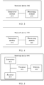
- FIG. 3 is a schematic block diagram of a terminal device 200 according to an embodiment of this application. As shown in FIG. 3 , the terminal device 200 includes:
- the processing module 220 is further configured to determine the preset time based on a preparation time for demodulating a physical downlink control channel PDCCH by the terminal device.
- the preset time is a time difference between a moment at which the transceiver module receives the first message and a moment at which the transceiver module receives the third message.
- the second message is a media access control layer control element MCE.
- duration of the preset time is less than or equal to 30 ms.
- the terminal device in this embodiment of this application may notify the network device of the preset time in advance. This helps quickly reduce a time for triggering resynchronization of an uplink secondary carrier cell, and improve an uplink throughput.
- FIG. 4 is a schematic block diagram of a network device 300 according to an embodiment of this application. As shown in FIG. 4 , the network device 300 includes:
- the preset time is a time difference between a moment at which the transceiver module sends the first message and a moment at which the transceiver module sends the third message.
- the second message is a media access control layer control element MCE.
- duration of the preset time is less than or equal to 30 ms.
- the terminal device may notify the network device of the preset time in advance. This helps quickly reduce a time for triggering resynchronization of an uplink secondary carrier cell, and improve an uplink throughput.
- FIG. 5 is a schematic structural diagram of a terminal device 400 according to an embodiment of this application.
- the terminal device 400 includes a processor 401, a memory 402, a receiver 403, and a transmitter 404. A communication connection is performed between these components.
- the memory 402 is configured to store an instruction
- the processor 401 is configured to execute the instruction stored in the memory 402, control the receiver 403 to receive information, and control the transmitter 404 to send information.
- the processor 401 is configured to execute the instruction stored in the memory 402, the processor 401 may be configured to perform an operation and/or a function corresponding to the processing module 220 in the terminal device 200.
- the receiver 403 and the transmitter 404 may be configured to perform an operation and/or a function corresponding to the transceiver module 210 in the terminal device 200. For brevity, details are not described herein again.
- FIG. 6 is a schematic structural diagram of a network device 500 according to an embodiment of this application.
- the network device 500 includes a processor 5601, a memory 502, a receiver 503, and a transmitter 504. A communication connection is performed between these components.
- the memory 502 is configured to store an instruction
- the processor 501 is configured to execute the instruction stored in the memory 502, control the receiver 503 to receive information, and control the transmitter 504 to send information.
- the processor 501 is configured to execute the instruction stored in the memory 502, the processor 501 may be configured to perform an operation and/or a function corresponding to the processing module 320 in the network device 300.
- the receiver 503 and the transmitter 504 may be configured to perform an operation and/or a function corresponding to the transceiver module 310 in the network device 300. For brevity, details are not described herein again.
- FIG. 7 is a schematic block diagram of a communications system 600 according to an embodiment of this application.
- the communications system 600 includes a terminal device 610 and/or a network device 620.
- the terminal device 610 may be the terminal device 200 or the terminal device 400
- the network device 620 may be the network device 300 or the network device 500.
- An embodiment of this application further provides a system chip.
- the system chip includes an input/output interface, at least one processor, at least one memory, and a bus.
- the at least one memory is configured to store an instruction
- the at least one processor is configured to invoke the instruction in the at least one memory, to perform operations of the methods in the foregoing aspects.
- the processor may be an integrated circuit chip and has a signal processing capability.
- steps in the foregoing method embodiments can be implemented by using a hardware integrated logic circuit in the processor, or by using instructions in a form of software.
- the processor may be a general-purpose processor, a digital signal processor (Digital Signal Processor, DSP), an application specific integrated circuit (Application Specific Integrated Circuit, ASIC), a field programmable gate array (Field Programmable Gate Array, FPGA) or another programmable logic device, a discrete gate or transistor logic device, or a discrete hardware component.
- DSP Digital Signal Processor
- ASIC Application Specific Integrated Circuit
- FPGA Field Programmable Gate Array
- the general-purpose processor may be a microprocessor, or the processor may be any conventional processor or the like. Steps of the methods disclosed with reference to the embodiments of this application may be directly executed and accomplished by using a hardware decoding processor, or may be executed and accomplished by using a combination of hardware and software modules in the decoding processor.
- a software module may be located in a mature storage medium in the art, such as a random access memory, a flash memory, a read-only memory, a programmable read-only memory, an electrically erasable programmable memory, a register, or the like. The storage medium is located in the memory, and the processor reads information in the memory and completes the steps in the foregoing methods in combination with hardware of the processor.
- the memory in the embodiments of this application may be a volatile memory or a non-volatile memory, or may include a volatile memory and a non-volatile memory.
- the non-volatile memory may be a read-only memory (Read-Only Memory, ROM), a programmable read-only memory (Programmable ROM, PROM), an erasable programmable read-only memory (Erasable PROM, EPROM), an electrically erasable programmable read-only memory (Electrically EPROM, EEPROM), or a flash memory.
- the volatile memory may be a random access memory (Random Access Memory, RAM), used as an external cache.
- RAMs may be used, for example, a static random access memory (Static RAM, SRAM), a dynamic random access memory (Dynamic RAM, DRAM), a synchronous dynamic random access memory (Synchronous DRAM, SDRAM), a double data rate synchronous dynamic random access memory (Double Data Rate SDRAM, DDR SDRAM), an enhanced synchronous dynamic random access memory (Enhanced SDRAM, ESDRAM), a synchlink dynamic random access memory (Synchlink DRAM, SLDRAM), and a direct rambus random access memory (Direct Rambus RAM, DR RAM).
- Static RAM static random access memory
- DRAM dynamic random access memory
- DRAM synchronous dynamic random access memory
- SDRAM double data rate synchronous dynamic random access memory
- Enhanced SDRAM, ESDRAM enhanced synchronous dynamic random access memory
- Synchlink DRAM, SLDRAM synchlink dynamic random access memory
- Direct Rambus RAM Direct Rambus RAM
- system and “network” may be used interchangeably in this specification.
- the term “and/or” in this specification describes only an association relationship for associated objects and represents that three relationships may exist. For example, A and/or B may represent the following three cases: Only A exists, both A and B exist, and only B exists.
- the character “/" in this specification generally indicates an “or” relationship between the associated objects.
- B corresponding to A indicates that B is associated with A, and B may be determined according to A.
- determining A according to B does not mean that B is determined according to A only; that is, B may also be determined according to A and/or other information.
- All or some of the foregoing embodiments may be implemented by using software, hardware, firmware, or any combination thereof.
- the embodiments may be implemented completely or partially in a form of a computer program product.
- the computer program product may include one or more computer instructions.
- the computer may be a general-purpose computer, a dedicated computer, a computer network, or other programmable apparatuses.
- the computer instructions may be stored in a computer-readable storage medium or may be transmitted from a computer-readable storage medium to another computer-readable storage medium.
- the computer instructions may be transmitted from a website, computer, server, or data center to another website, computer, server, or data center in a wired (for example, a coaxial cable, an optical fiber, or a digital subscriber line (DSL)) or wireless (for example, infrared, radio, and microwave, or the like) manner.
- the computer-readable storage medium may be any usable medium accessible by a computer, or a data storage device, such as a server or a data center, integrating one or more usable media.
- the usable medium may be a magnetic medium (for example, a floppy disk, a hard disk, or a magnetic disk), an optical medium (for example, a DVD), a semiconductor medium (for example, a solid-state drive Solid State Disk (SSD)), or the like.
- a magnetic medium for example, a floppy disk, a hard disk, or a magnetic disk
- an optical medium for example, a DVD
- a semiconductor medium for example, a solid-state drive Solid State Disk (SSD)
- the disclosed systems, apparatuses, and methods may be implemented in other manners.
- the described apparatus embodiments are merely examples.
- the unit division is merely logical function division and may be other division in actual implementation.
- a plurality of units or components may be combined or integrated into another system, or some features may be ignored or not performed.
- the displayed or discussed mutual couplings or direct couplings or communication connections may be implemented by using some interfaces.
- the indirect couplings or communication connections between the apparatuses or units may be implemented in electronic, mechanical, or other forms.
- the units described as separate parts may or may not be physically separate, and parts displayed as units may or may not be physical units, may be located in one position, or may be distributed on a plurality of network units. Some or all of the units may be selected based on actual requirements to achieve the objectives of the solutions of the embodiments.
- the functions When the functions are implemented in the form of a software functional unit and sold or used as an independent product, the functions may be stored in a computer-readable storage medium.
- the software product is stored in a storage medium, and includes several instructions for instructing a computer device (which may be a personal computer, a server, a network device, or the like) to perform all or some of the steps of the methods described in the embodiments of this application.
- the foregoing storage medium includes: any medium that can store program code, such as a USB flash drive, a removable hard disk, a read-only memory, a random access memory, a magnetic disk, or an optical disc.
Landscapes
- Engineering & Computer Science (AREA)
- Computer Networks & Wireless Communication (AREA)
- Signal Processing (AREA)
- Mobile Radio Communication Systems (AREA)
Applications Claiming Priority (1)
| Application Number | Priority Date | Filing Date | Title |
|---|---|---|---|
| PCT/CN2017/106134 WO2019071589A1 (fr) | 2017-10-13 | 2017-10-13 | Procédé de transmission, dispositif terminal et dispositif de réseau |
Publications (2)
| Publication Number | Publication Date |
|---|---|
| EP3687129A1 true EP3687129A1 (fr) | 2020-07-29 |
| EP3687129A4 EP3687129A4 (fr) | 2020-11-04 |
Family
ID=66100217
Family Applications (1)
| Application Number | Title | Priority Date | Filing Date |
|---|---|---|---|
| EP17928419.5A Pending EP3687129A4 (fr) | 2017-10-13 | 2017-10-13 | Procédé de transmission, dispositif terminal et dispositif de réseau |
Country Status (5)
| Country | Link |
|---|---|
| US (1) | US11510158B2 (fr) |
| EP (1) | EP3687129A4 (fr) |
| JP (1) | JP6992173B2 (fr) |
| CN (1) | CN111194542B (fr) |
| WO (1) | WO2019071589A1 (fr) |
Families Citing this family (2)
| Publication number | Priority date | Publication date | Assignee | Title |
|---|---|---|---|---|
| WO2024045042A1 (fr) * | 2022-08-31 | 2024-03-07 | 北京小米移动软件有限公司 | Procédé, appareil et dispositif de déclenchement d'interaction de capacité et support de stockage |
| CN118828734B (zh) * | 2023-07-13 | 2025-10-03 | 中国移动通信集团设计院有限公司 | 小区切换方法、装置、设备和存储介质 |
Family Cites Families (10)
| Publication number | Priority date | Publication date | Assignee | Title |
|---|---|---|---|---|
| CN101583081B (zh) * | 2008-05-15 | 2012-01-25 | 电信科学技术研究院 | 一种同步承载建立的方法、系统和装置 |
| JP5278035B2 (ja) * | 2009-02-25 | 2013-09-04 | ソニー株式会社 | 通信装置及び通信方法、コンピューター・プログラム、並びに通信システム |
| CN103368763B (zh) * | 2012-04-10 | 2016-03-09 | 华为技术有限公司 | 监听的控制方法及设备 |
| EP2921018B1 (fr) | 2012-11-13 | 2020-09-02 | Nokia Technologies Oy | Indication de retard d'activation de cellule secondaire |
| CN104871636B (zh) * | 2013-12-20 | 2019-04-05 | 华为技术有限公司 | 一种辅载波变更的方法、终端、网络设备及系统 |
| JP6535970B2 (ja) * | 2014-02-26 | 2019-07-03 | シャープ株式会社 | 基地局装置、端末装置、および、無線通信方法 |
| CN105592560A (zh) * | 2014-10-21 | 2016-05-18 | 中兴通讯股份有限公司 | 上行辅载波状态控制方法、装置及基站 |
| CN111541527B (zh) * | 2015-11-20 | 2022-04-22 | 华为技术有限公司 | 一种下行同步的方法、装置及系统 |
| CN107241780A (zh) * | 2016-03-28 | 2017-10-10 | 北京信威通信技术股份有限公司 | 小区的上行同步方法及系统 |
| CN107196750B (zh) * | 2017-06-08 | 2020-03-20 | 上海华为技术有限公司 | 一种可重同步触发方法及基站 |
-
2017
- 2017-10-13 WO PCT/CN2017/106134 patent/WO2019071589A1/fr not_active Ceased
- 2017-10-13 EP EP17928419.5A patent/EP3687129A4/fr active Pending
- 2017-10-13 JP JP2020520825A patent/JP6992173B2/ja active Active
- 2017-10-13 CN CN201780095742.9A patent/CN111194542B/zh active Active
-
2020
- 2020-04-09 US US16/844,852 patent/US11510158B2/en active Active
Also Published As
| Publication number | Publication date |
|---|---|
| JP6992173B2 (ja) | 2022-02-03 |
| JP2020537447A (ja) | 2020-12-17 |
| CN111194542A (zh) | 2020-05-22 |
| US20200236642A1 (en) | 2020-07-23 |
| US11510158B2 (en) | 2022-11-22 |
| EP3687129A4 (fr) | 2020-11-04 |
| WO2019071589A1 (fr) | 2019-04-18 |
| CN111194542B (zh) | 2021-08-20 |
Similar Documents
| Publication | Publication Date | Title |
|---|---|---|
| US11825519B2 (en) | Random access method, terminal device, network device, and storage medium | |
| CN110063068B (zh) | 用于随机接入的方法和终端设备 | |
| CN110073711B (zh) | 用于随机接入的方法和设备 | |
| CN111132294B (zh) | 无线通信方法和设备 | |
| EP3923510B1 (fr) | Procédé de communication sans fil, dispositif de réseau et dispositif terminal | |
| US11792749B2 (en) | Information transmission method and device | |
| CN111294909A (zh) | 无线通信方法和设备 | |
| EP3720209A1 (fr) | Procédé de communication sans fil, terminal et dispositif de réseau | |
| EP3681200A1 (fr) | Procédé de communication sans fil, dispositif de réseau et dispositif terminal | |
| EP3731591A1 (fr) | Procédé de communication sans fil, équipement terminal et dispositif de réseau | |
| CN112135308A (zh) | 用于配置通信参数的方法和设备 | |
| US11510158B2 (en) | Transmission method, terminal device, and network device | |
| US11622376B2 (en) | Wireless communications method and device | |
| KR20210021053A (ko) | 채널 액세스 유형 지시 방법, 단말 기기 및 네트워크 기기 | |
| WO2018227500A1 (fr) | Procédé pour déterminer un nombre d'occurrences de transmission de préambule d'accès aléatoire, dispositif de réseau et dispositif terminal | |
| CN109565886B (zh) | 发送随机接入前导的方法和终端设备 |
Legal Events
| Date | Code | Title | Description |
|---|---|---|---|
| STAA | Information on the status of an ep patent application or granted ep patent |
Free format text: STATUS: THE INTERNATIONAL PUBLICATION HAS BEEN MADE |
|
| PUAI | Public reference made under article 153(3) epc to a published international application that has entered the european phase |
Free format text: ORIGINAL CODE: 0009012 |
|
| STAA | Information on the status of an ep patent application or granted ep patent |
Free format text: STATUS: REQUEST FOR EXAMINATION WAS MADE |
|
| 17P | Request for examination filed |
Effective date: 20200423 |
|
| AK | Designated contracting states |
Kind code of ref document: A1 Designated state(s): AL AT BE BG CH CY CZ DE DK EE ES FI FR GB GR HR HU IE IS IT LI LT LU LV MC MK MT NL NO PL PT RO RS SE SI SK SM TR |
|
| AX | Request for extension of the european patent |
Extension state: BA ME |
|
| A4 | Supplementary search report drawn up and despatched |
Effective date: 20201001 |
|
| RIC1 | Information provided on ipc code assigned before grant |
Ipc: H04L 27/26 20060101AFI20200925BHEP Ipc: H04W 56/00 20090101ALI20200925BHEP |
|
| DAV | Request for validation of the european patent (deleted) | ||
| DAX | Request for extension of the european patent (deleted) | ||
| STAA | Information on the status of an ep patent application or granted ep patent |
Free format text: STATUS: EXAMINATION IS IN PROGRESS |
|
| 17Q | First examination report despatched |
Effective date: 20220221 |