EP3687154A1 - Ensemble caméra et terminal - Google Patents
Ensemble caméra et terminal Download PDFInfo
- Publication number
- EP3687154A1 EP3687154A1 EP19205999.6A EP19205999A EP3687154A1 EP 3687154 A1 EP3687154 A1 EP 3687154A1 EP 19205999 A EP19205999 A EP 19205999A EP 3687154 A1 EP3687154 A1 EP 3687154A1
- Authority
- EP
- European Patent Office
- Prior art keywords
- cameras
- hole
- rotation
- plate
- camera assembly
- Prior art date
- Legal status (The legal status is an assumption and is not a legal conclusion. Google has not performed a legal analysis and makes no representation as to the accuracy of the status listed.)
- Granted
Links
Images



Classifications
-
- H—ELECTRICITY
- H04—ELECTRIC COMMUNICATION TECHNIQUE
- H04N—PICTORIAL COMMUNICATION, e.g. TELEVISION
- H04N23/00—Cameras or camera modules comprising electronic image sensors; Control thereof
- H04N23/50—Constructional details
-
- H—ELECTRICITY
- H04—ELECTRIC COMMUNICATION TECHNIQUE
- H04N—PICTORIAL COMMUNICATION, e.g. TELEVISION
- H04N23/00—Cameras or camera modules comprising electronic image sensors; Control thereof
- H04N23/60—Control of cameras or camera modules
- H04N23/698—Control of cameras or camera modules for achieving an enlarged field of view, e.g. panoramic image capture
-
- H—ELECTRICITY
- H04—ELECTRIC COMMUNICATION TECHNIQUE
- H04M—TELEPHONIC COMMUNICATION
- H04M1/00—Substation equipment, e.g. for use by subscribers
- H04M1/02—Constructional features of telephone sets
- H04M1/0202—Portable telephone sets, e.g. cordless phones, mobile phones or bar type handsets
- H04M1/026—Details of the structure or mounting of specific components
- H04M1/0264—Details of the structure or mounting of specific components for a camera module assembly
-
- H—ELECTRICITY
- H04—ELECTRIC COMMUNICATION TECHNIQUE
- H04N—PICTORIAL COMMUNICATION, e.g. TELEVISION
- H04N23/00—Cameras or camera modules comprising electronic image sensors; Control thereof
- H04N23/45—Cameras or camera modules comprising electronic image sensors; Control thereof for generating image signals from two or more image sensors being of different type or operating in different modes, e.g. with a CMOS sensor for moving images in combination with a charge-coupled device [CCD] for still images
-
- H—ELECTRICITY
- H04—ELECTRIC COMMUNICATION TECHNIQUE
- H04N—PICTORIAL COMMUNICATION, e.g. TELEVISION
- H04N23/00—Cameras or camera modules comprising electronic image sensors; Control thereof
- H04N23/50—Constructional details
- H04N23/54—Mounting of pick-up tubes, electronic image sensors, deviation or focusing coils
-
- H—ELECTRICITY
- H04—ELECTRIC COMMUNICATION TECHNIQUE
- H04N—PICTORIAL COMMUNICATION, e.g. TELEVISION
- H04N23/00—Cameras or camera modules comprising electronic image sensors; Control thereof
- H04N23/57—Mechanical or electrical details of cameras or camera modules specially adapted for being embedded in other devices
-
- H—ELECTRICITY
- H04—ELECTRIC COMMUNICATION TECHNIQUE
- H04N—PICTORIAL COMMUNICATION, e.g. TELEVISION
- H04N23/00—Cameras or camera modules comprising electronic image sensors; Control thereof
- H04N23/58—Means for changing the camera field of view without moving the camera body, e.g. nutating or panning of optics or image sensors
-
- H—ELECTRICITY
- H04—ELECTRIC COMMUNICATION TECHNIQUE
- H04N—PICTORIAL COMMUNICATION, e.g. TELEVISION
- H04N23/00—Cameras or camera modules comprising electronic image sensors; Control thereof
- H04N23/60—Control of cameras or camera modules
- H04N23/695—Control of camera direction for changing a field of view, e.g. pan, tilt or based on tracking of objects
-
- H—ELECTRICITY
- H04—ELECTRIC COMMUNICATION TECHNIQUE
- H04N—PICTORIAL COMMUNICATION, e.g. TELEVISION
- H04N23/00—Cameras or camera modules comprising electronic image sensors; Control thereof
- H04N23/90—Arrangement of cameras or camera modules, e.g. multiple cameras in TV studios or sports stadiums
-
- H—ELECTRICITY
- H04—ELECTRIC COMMUNICATION TECHNIQUE
- H04M—TELEPHONIC COMMUNICATION
- H04M2250/00—Details of telephonic subscriber devices
- H04M2250/20—Details of telephonic subscriber devices including a rotatable camera
Definitions
- a mobile phone is no longer just a tool for voice communications or surfing the Internet, but also essentially replaces a camera in daily life because of its increasingly powerful camera function.
- the mobile phone therefore has become a major tool carried around by the user for image capturing and video recording.
- the present disclosure relates generally to the field of electronic device technologies, and more specifically to a camera assembly and a terminal.
- Embodiments of the present disclosure provide a camera assembly and a terminal.
- a camera assembly including: a base; and two cameras located on the base.
- an angle between a first plane and a second plane is greater than 0 degrees and less than 180 degrees, back surfaces of the two cameras lean towards each other, the first plane is a plane perpendicular to an optical axis direction of one of the cameras, and the second plane is a plane perpendicular to an optical axis direction of the other of the cameras.
- the base includes: a rotation device fixedly connected to the two cameras, wherein the rotation device rotates to drive the two cameras to rotate from a parallel state to the tilted state or from the tilted state to the parallel state; and a control device connected to the rotation device to control rotation of the rotation device.
- a rotation device fixedly connected to the two cameras, wherein the rotation device rotates to drive the two cameras to rotate from a parallel state to the tilted state or from the tilted state to the parallel state
- a control device connected to the rotation device to control rotation of the rotation device.
- the rotation device includes: two rotation brackets, each of the rotation brackets being fixedly connected to one of the two cameras (2A, 2B); and a support bracket rotatably connected with the two rotation brackets to restrict a rotating direction of the two rotation brackets, wherein when the control device controls rotation of the two rotation brackets, the support bracket restricts the control devices to drive the two cameras to rotate from the parallel state to the tilted state, or to drive the two cameras to rotate from the tilted state to the parallel state.
- the support bracket has two receiving chambers, a partition plate is arranged between the two receiving chambers, the partition plate defines a through slot, and each of the two rotation brackets is placed in one of the two receiving chambers; each of the two receiving chambers is defined by a baseplate, a first vertical plate, and a second vertical plate, the first vertical plate is opposite the second vertical plate, wherein the baseplate is provided with at least one stop block and at least one resilient tab, a distance between the stop block and the partition plate is less than a distance between the resilient tab and the partition plate, and the first vertical plate defines a first through hole, and the second vertical plate defines a second through hole opposite the first through hole; each of the two rotation brackets comprises a first side plate and a second side plate opposite each other, and a third side plate connected to a side edge of the first side plate and a side edge of the second side plate, third side plates of the two rotation brackets are opposite each other, a moving plate (1114) extends from a bottom of the third side plate, and part
- control device includes: an electromagnet arranged on the partition plate; a controller configured to energize or de-energize the electromagnet, the moving plate is located between the electromagnet and the baseplate, and the moving plate is made from ferromagnetic material.
- the partition plate defines a receiving groove, and the electromagnet is arranged in the receiving groove.
- the electromagnet is fixed to the partition plate.
- walls defining the first through hole, the second through hole, the third through hole and the fourth through hole are provided with internal threads, the first through hole matches the third through hole, and the second through hole matches the fourth through hole;
- the first shaft and the second shaft are screws matching the internal threads, each of the screws comprises a screw head and a screw rod, and a screw cap is fixed at an end, opposite the screw head, of the screw rod.
- each of the two cameras is fixed to one of the two rotation brackets by means of a bonding layer.
- the moving plate of one of the two rotation brackets includes one first mobile plate
- the moving plate of the other one of the two rotation brackets includes two identical second mobile plates
- the two identical second mobile plates are arranged on two sides of the first mobile plate, and distances from the two identical second mobile plates to the first mobile plate are the same.
- two stop blocks are provided in each of the two receiving chambers, and two resilient tabs are provided in each of the two receiving chambers.
- the angle between the first plane and the second plane is greater than 90 degrees and less than 180 degrees.
- a terminal including the above camera assembly.
- the terminal further includes a processing component including one or more processors to execute an instruction of synthesizing a plurality of pictures taken by the two cameras into one or more wide-angle pictures.
- the two cameras are rear cameras.
- the technical scheme provided by the embodiment of the present disclosure may include the following beneficial effects: in the present embodiment, two cameras are adopted and the base is used to make the two cameras lean against each other, thus expanding the photographing range of the camera assembly, such that two non-wide-angle cameras with small photographing angle can constitute the above camera assembly, which can take a wide viewing picture with comparatively good picture details and features.
- orientation terms such as “inner,” “outer” or the like are generally in terms of a contour of the corresponding component.
- the terms such as “first” and “second” in embodiments of the present disclosure are used to distinguish one element from another element, and are not intended to indicate or imply any sequence or relative importance.
- a wide-angle camera of a terminal has a large viewing angle, and can take a comparatively wide picture and be used to capture large-scale photographs.
- a camera light sensing chip due to a fixed area of a camera light sensing chip, there are more distortions in details of the picture compared with a small-view-angle camera.
- various embodiments of the present disclosure provide a camera assembly, and the camera assembly includes a base and two cameras, and the two cameras are located on the base.
- an angle between a first plane and a second plane is greater than 0 degree and less than 180 degrees, and back surfaces of the two cameras lean towards each other.
- the first plane is a plane perpendicular to an optical axis direction of one of the cameras and the second plane is a plane perpendicular to an optical axis direction of the other one of the cameras.
- the photographing range of the two cameras must be larger than that of a single camera and the two cameras are leant against each other, such that the photographing range of the camera assembly can be further expanded.
- the two cameras with a smaller photographing angle can be used to form the above-mentioned camera assembly, which can take a broader picture with comparatively good details and features.
- FIG. 1 is a schematic view of a camera assembly according to an exemplary embodiment. As illustrated in FIG. 1 , the camera assembly includes a base 1 and two cameras, namely a camera 2A and a camera 2B.
- the camera 2A and the camera 2B are arranged on the base 1, and the base 1 sets the camera 2A and the camera 2B in a tilted state. As illustrated in FIG. 1 .
- an angle ⁇ between a first plane 21 and a second plane 22 is greater than 0 degree and less than 180 degrees, and back surfaces of the two cameras (a back surface 20 A of the camera 2A and a back surface 20B of the camera 2B) are opposite each other, that means the back surface 20 A and the back surface 20B lean towards each other.
- the first plane 21 is a plane perpendicular to an optical axis direction A of the cameras 2A
- the second plane 22 is a plane perpendicular to an optical axis direction A* of the camera 2B.
- the optical axis direction of a camera refers to a lens optical axis direction of the camera, and also represents a photographing direction of the camera.
- the photographing range of the camera assembly further expands to both sides, such that a wide-angle camera is no long needed, and only two non-wide-angle cameras with a smaller photographing angle are needed.
- the camera assembly can also have a wider viewing angle and take a comparatively wide picture.
- the non-wide-angle camera can also take pictures having comparatively good details.
- the angle ⁇ between the first plane 21 and the second plane 22 is greater than 0 degree and less than 180 degrees.
- a value of the angle reflects the tilting degree of the two cameras.
- a large angle indicates a small tilting degree of the two cameras.
- a small angle indicates a large tilting degree of the two cameras.
- the value of angle needs to ensure that a plurality of pictures taken by the cameras 2A and the camera 2B separately can be synthesized into one or a plurality of wide-angle pictures.
- the angle can be determined by respective photographing angles and distances of the two cameras. In an embodiment, the angle may be greater than 90 degrees and less than 180 degrees.
- the base 1 can fix the two cameras, namely the camera 2A and the camera 2B in the tilted state as illustrated in FIG. 1 .
- the base may also rotate the two cameras to the tilted state when a large view picture needs to be taken.
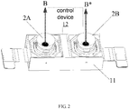
- FIG. 2 is a schematic view of a camera assembly according to an exemplary embodiment. As illustrated in FIG. 2 , the above base 1 includes a rotation structure 11 and a control structure 12.
- the rotation structure 11 is fixedly connected to the two cameras (the camera 2A and the camera 2B) and rotates to drive each of the cameras to rotate from a parallel state to the tilted state or from the tilted state to the parallel state.
- the control structure 12 is connected with the rotation structure 11 for controlling the rotation of the rotation structure 11.
- a photographing surface of a camera lens is a front surface of the camera, and a surface that is opposite the front surface of the camera is the back surface of the camera, and a side surface located between the front surface and the back surface of the camera is the side surface of the camera.
- the surfaces of the two cameras opposite each other are side surfaces of the two cameras.
- control structure 12 can control the rotation structure 11 to rotate the camera 2A and the camera 2B from the parallel state illustrated in FIG. 2 to the tilted state illustrated in FIG. 1 .
- control structure controls the rotation structure to rotate the two cameras from the tilted state illustrated in FIG. 1 to the parallel state illustrated in FIG. 2 .
- the photographing range of the camera assembly with the camera 2A and the camera 2B in the tilted state illustrated in FIG. 1 is larger than that of the camera assembly with the camera 2A and the camera 2B in the parallel state illustrated in FIG. 2 .
- the base can include the control structure and the rotation structure, such that the two cameras can be rotated in reverse directions to put the two cameras in the tilted state when needed, and thus, the viewing angle of the camera assembly is expanded to take a wide picture.
- the two cameras can also be restored to the normal parallel state in order to reset the camera and take a normal picture.
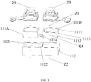
- FIG. 3 is an exploded view of a camera assembly according to an exemplary embodiment.
- the rotation structure 11 includes two rotation brackets, namely a rotation bracket 111A and a rotation bracket 111B, and a support bracket 112.
- each of the two rotation brackets is fixedly connected to one corresponding camera.
- the rotation bracket 111A may be fixedly connected to the camera 2A
- the rotation bracket 111B may be fixedly connected to the camera 2B.
- the rotation brackets rotate to drive the fixed cameras to rotate.
- the support bracket 112 is rotatably connected with the two rotation brackets to restrict rotating directions of the two rotation brackets.
- the control structure 12 controls the two rotation brackets to rotate
- each of the two rotation brackets only rotates backwards and forwards in one direction, but cannot freely rotate in other directions.
- the rotation brackets only drive the fixedly connected cameras to rotate from the parallel state to the tilted state, or to drive the corresponding cameras to rotate from the tilted state to the parallel state.
- a rotation device can be provided with two rotation brackets and one support bracket, each of the two rotation brackets is fixedly connected to one corresponding camera.
- the support bracket is rotatably connected to the two rotation brackets to restrict the rotating directions of the two rotation brackets.
- the rotation brackets are restricted to drive the corresponding cameras to rotate from the parallel state to the tilted state, or drive the corresponding cameras to rotate from the tilted state to the parallel state in a simple way.
- the support bracket 112 includes two receiving chambers 1121, and a partition plate 1122 is arranged between the two receiving chambers, and one rotation bracket is placed correspondingly in the receiving chamber 1121.
- FIG. 4 is a schematic view of a support bracket according to an exemplary embodiment. As illustrated in FIG. 4 , the partition plate 1122 defines a through slot 1123.
- the receiving chamber 1121 includes a first baseplate 11211, and a first vertical plate 11212 and a second vertical plate 11213 which are opposite each other.
- the first baseplate 11211 is provided with at least one stop block 1124 and at least one resilient tab 1125.
- a distance between the stop block 1124 and the partition plate 1122 is less than a distance between the resilient tab 1125 and the partition plate 1122. That is, the stop block 1124 is adjacent to the partition plate 1222, and the resilient tab 1125 is away from the partition plate 1222.
- each first baseplate 11211 is provided with two stop blocks 1124 and two resilient tabs 1125, and the two stop blocks 1124 are symmetrically arranged about an axis on the first baseplate 11211, and the two resilient tabs 1125 are also symmetrically arranged about an axis on the first baseplate 11211.
- the first vertical plate 11212 defines a first through hole K1, and the second vertical plate 11213 correspondingly defines a second through hole K2.
- the two rotation brackets are illustrated in FIG. 3 , taking the rotation bracket 111B which is marked as an example, the rotation bracket 111B includes a first side plate 1111 and a second side plate 1112 opposite each other, and a third side plate 1113 connecting with side edges of the first side plate 1111 and the second side plate 1112.
- Third side plates 1113 of the two rotation brackets are opposite each other, and a bottom of the third side plate 1113 extends outwards to form a moving plate 1114, and part of the moving plate 1114 is located in the through slot 1123.
- the first side plate 1111 defines a third through hole K3 (not illustrated in the drawings), and a first shaft Z1 is arranged in the third through hole K3.
- the second side plate 1112 defines a fourth through hole K4, and a second shaft Z2 is arranged in the fourth through hole K4.
- the first shaft Z1 passes through the first through hole K1, in this way, the first shaft Z1 rotatably connects the first side plate 1111 with the first vertical plate 11212.
- the second shaft Z2 passes through the second through hole K2, and thus the second shaft Z2 rotatably connects the second side plate 1112 with the second vertical plate 11213.
- the first shaft Z1 and the second shaft Z2 rotatably connect the rotation bracket 111 with the receiving chamber 1121.
- the rotation bracket 111A has the same structure as the rotation bracket 111B at corresponding positions, which will not be repeated here.
- FIG. 5 is a view of a structure of a camera assembly according to an exemplary embodiment, in which a single camera rotates to a tilted state. As illustrated in FIG. 5 , the rotation bracket drives the camera to rotate about an O-O* axis.
- the rotation bracket after being connected to the support bracket 112 by the two shafts, the rotation bracket only rotates about the axis defined by the two shafts, but the stop block 1124 and the through slot 1123 on the support bracket 112 restrict the rotation bracket to rotate within a small-angle range.
- the control structure 12 exerts a pulling force on the moving plate 1114 in the through slot 1123 to make the moving plate move away from the first baseplate 11211, the rotation bracket 111 is driven to rotate, the resilient tab 1125 is pressed downwards and deformed. The moving plate is stopped by the through slot 1123 after rotating to a certain angle and stops moving.
- the camera fixedly connected with the rotation bracket rotates from the parallel state to the tilted state, releasing the pulling force exerted on the moving plate 1114 in the through slot 1123.
- the rotation bracket rotates back under an elastic force of the resilient tab 1125 until the rotation bracket is stopped by the stop block 1124, and then the camera fixedly connected with the rotation bracket rotates from the tilted state to the parallel state.
- the support bracket and the rotation brackets according to various embodiments of the disclosure may be configured as above, and the structure is simple and easy to realize.
- the control structure includes: an electromagnet 121 arranged on the partition plate 1122 (in which the electromagnet 121 may be fixed on the partition plate 1122), and a controller 122 configured to energize or de-energize the electromagnet 121.
- the moving plate is located between the electromagnet 121 and the first baseplate 11211, and the moving plate 1114 is made from ferromagnetic material.
- the electromagnet 121 After the controller 122 energizes the electromagnet 121, the electromagnet 121 generates a magnetic field which exerts an electromagnetic attraction F on the moving plate 1114 towards the electromagnet 121, and the electromagnetic attraction F makes the moving plate 1114 to lean outwards and towards the electromagnet 121, which drives the rotation bracket to rotate outward.
- the rotation bracket rotates outwards with the camera.
- the resilient tab 1125 on the first baseplate 1211 is pressed, and when the resilient tab 1125 is deformed to a certain position, the through slot 1123 prevents the moving plate 1114 from further leaning and rotating.
- the two cameras are in the tilted state to take a wide picture.
- the controller 122 can de-energize the electromagnet 121, which releases the electromagnetic attraction exerted on the moving plate 1114 in the through slot 1123, and the resilient tab under the rotation bracket exerts a pulling force away from the first baseplate 11211 by a restoring force generated by its own deformation, and the pulling force makes the rotation bracket rotate back with the camera.
- the stop blocks 1124 prevent the rotation brackets from continuing to rotate, thereby maintaining the two cameras in the parallel state.
- the controller energizes or de-energizes the electromagnet to control the rotation of the rotation brackets, and the structure is simple and easy to realize.
- the partition plate 1122 defines a receiving groove 11221, and the electromagnet 121 is fixed in the receiving groove 11221.
- the electromagnet may be fixed in the receiving groove of the partition plate to ensure the structural stability of the camera assembly.
- hole walls defining the first through hole K1, the second through hole K2, the third through hole K3 and the fourth through hole K4 are provided with internal threads.
- the first through hole K1 matches the third through hole K3, positions of them correspond to each other to enable the first shaft Z1 to pass through the first through hole K1 and the third through hole K3.
- the second through hole K2 matches the fourth through hole K4, positions of them correspond to each other to enable the second shaft Z2 to pass through the second through hole K2 and the fourth through hole K4.
- the first shaft Z1 and the second shaft Z2 are screws matching the internal threads.
- the first shaft Z1 and the second shaft Z2 are therefore threadedly connected with the rotation bracket and the support bracket.
- Each of the screw includes a screw head and a screw rod.
- the screw rod is provided with a screw cap fixed to an end opposite the screw head of the screw rod, such that the screw can be prevented from failing from the through hole.
- the first shaft and the second shaft rotate in a screw manner, which prevents the first shaft and the second shaft rotating freely, and the screw cap fixed on the screw prevents the screw from failing so as to ensure the structural stability of the camera assembly.
- a bonding layer is arranged between the camera 2 and the corresponding rotation bracket.
- the camera is adhered and fixed to the rotation bracket by the bonding layer and the fixation is simple and easy to realize.
- the bottom of the third side plate 1113 of one rotation bracket 111B extends and forms a first mobile plate
- the bottom of the third side plate 1113 of the other rotation bracket 111A extends and forms two identical second mobile plates.
- the two identical second mobile plates are arranged on both sides of the first mobile plate, and distances from the two identical second mobile plates to the first mobile plate are the same.
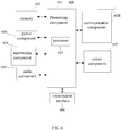
- FIG. 6 is a block diagram of a terminal according to an exemplary embodiment.
- a terminal 600 may be a mobile phone, a game console, a computer, a tablet device, a personal digital assistant, etc.
- the terminal 600 may include one or more of the following components: a processing component 601, a memory 602, a power component 603, a multimedia component 604, an audio component 605, an input/output (I/O) interface 606, a sensor component 607, and a communication component 608.
- a processing component 601 a memory 602, a power component 603, a multimedia component 604, an audio component 605, an input/output (I/O) interface 606, a sensor component 607, and a communication component 608.
- the processing component 601 usually controls the overall operation of terminal 600, such as operations associated with display, telephone call, data communication, camera operation and recording operation.
- the processing component 601 may include one or more processors 620 to execute instructions, such as an instruction of synthesizing a plurality of pictures taken by the two cameras into one or more wide-angle pictures to achieve wide-angle effect.
- the processing component 601 may include one or more modules to facilitate interaction between the processing component 601 and other components.
- the processing component 601 may include a multimedia module to facilitate interaction between the multimedia component 604 and the processing component 601, and the processing component 601 may also include the above controller 122 to control the rotation of the two cameras in the camera assembly.
- the memory 602 is configured to store various types of data to support operation at the terminal 600. Examples of these data include instructions for any application or method that operates on the terminal 600, such as contact data, phone book data, messages, pictures, videos, etc.
- the memory 602 may be achieved by any type of volatile or non-volatile storage devices or their combination, such as a static random access memory (SRAM), an electrically erasable programmable read only memory (EEPROM), an erasable programmable read-only memory (EPROM), a programmable read-only memory (PROM), a read-only memory (ROM), a magnetic memory, a flash memory, a magnetic or optical disc.
- SRAM static random access memory
- EEPROM electrically erasable programmable read only memory
- EPROM erasable programmable read-only memory
- PROM programmable read-only memory
- ROM read-only memory
- magnetic memory a magnetic memory
- flash memory a flash memory
- magnetic or optical disc a magnetic or optical disc.
- the power component 603 provides power for various components of the terminal 600.
- the power component 603 may include a power management system, one or more power sources, and other components associated with generating, managing and distributing power for the terminal 600.
- the multimedia component 604 includes a screen providing an output interface between the terminal 600 and a user.
- the screen may include a liquid crystal display (LCD) and a touch panel (TP).
- the screen can include an OLED (organic light emitting diode) display, or other types of displays.
- the screen may be implemented as a touch screen to receive input signals from the user.
- the touch panel includes one or more touch sensors to sense touch, sliding and gestures on the touch panel.
- the touch sensor may not only sense the boundary of the touch or sliding operation, but also detect the duration and pressure associated with the touch or sliding operation.
- the multimedia component 604 can include a front camera, and the camera assembly comprising the two rear cameras.
- the front camera and/or rear cameras may receive external multimedia data.
- Each of the front camera and the rear cameras may be a fixed optical lens system with focal length and optical zoom capability.
- the audio component 605 is configured to output and/or input audio signals.
- the audio component 605 includes a microphone (MIC).
- the microphone When the terminal 600 is in an operational mode, such as a calling mode, a recording mode and a speech recognition mode, the microphone is configured to receive external audio signals.
- the received audio signal may be further stored in the memory 602 or transmitted via the communication component 608.
- the audio component 605 also includes a speaker for outputting audio signals.
- the I/O interface 606 is configured to provide interface between the processing component 601 and a peripheral interface module, the above peripheral interface module may be a keyboard, a click wheel, a button, etc.
- the button may include, but is not limited to, a home page button, a volume button, a start button and a lock button.
- modules may have modular configurations, or are composed of discrete components, but nonetheless can be referred to as “modules” in general.
- the "components,” “portions,” “modules” or “units” referred to herein may or may not be in modular forms.
- the sensor component 607 includes one or more sensors to provide status assessments of various aspects of the terminal 600.
- the sensor component 607 may detect the on/off state of the terminal 600, relative positioning of components, such as a display and a keypad of terminal 600.
- the sensor component 607 may also detect the position change of the terminal 600 or a component of the terminal 600, and presence or absence of user contact with the terminal 600, the orientation or acceleration/deceleration of terminal 600 and the temperature change of terminal 600.
- the sensor component 607 may include a proximity sensor configured to detect the presence of a nearby object without any physical contact.
- the sensor module 607 may also include an optical sensor, such as a CMOS or CCD image sensor, so as to use in imaging applications.
- the sensor component 607 may also include an acceleration sensor, a gyroscope sensor, a magnetic sensor, a pressure sensor or a temperature sensor.
- the communication component 608 is configured to facilitate wired or wireless communication between the terminal 600 and other devices.
- the terminal 600 may access wireless networks based on communication standards, such as Wi-Fi, 2G, 3G, 4G, or 5G.
- the communication component 608 receives broadcast signals or broadcast related information from an external broadcast management system via a broadcast channel.
- the communication component 608 also includes a near field communication (NFC) module to facilitate short-range communication.
- NFC near field communication
- the NFC module may be implemented based on radio frequency identification (RFID) technology, infrared data association (IrDA) technology, ultra-wideband (UWB) technology, Bluetooth (BT) technology and other technologies.
- RFID radio frequency identification
- IrDA infrared data association
- UWB ultra-wideband
- Bluetooth Bluetooth
- the terminal 600 may be implemented by one or more application specific integrated circuits (ASIC), digital signal processors (DSPs), digital signal processing devices (DSPDs), programmable logic devices (PLDs), field programmable gate arrays (FPGAs), controllers, microcontrollers, microprocessors or other electronic components by performing the above methods.
- ASIC application specific integrated circuits
- DSPs digital signal processors
- DSPDs digital signal processing devices
- PLDs programmable logic devices
- FPGAs field programmable gate arrays
- controllers microcontrollers, microprocessors or other electronic components by performing the above methods.
- a non-transitory computer-readable storage medium including instructions is provided, such as the memory 602 including instructions, and the above instructions may be executed by the processor 620 of the terminal 600 so as to accomplish the above method.
- the non-transitory computer-readable storage medium may be the ROM, a random-access memory (RAM), a CD-ROM, a tape, a floppy disk, an optical data storage device, etc.
- the operations described in this disclosure can be implemented as operations performed by a data processing apparatus on data stored on one or more computer-readable storage devices or received from other sources.
- the terms “some embodiments,” “example,” and the like may indicate a specific feature described in connection with the embodiment or example, a structure, a material or feature included in at least one embodiment or example.
- the schematic representation of the above terms is not necessarily directed to the same embodiment or example.
Landscapes
- Engineering & Computer Science (AREA)
- Signal Processing (AREA)
- Multimedia (AREA)
- Human Computer Interaction (AREA)
- Studio Devices (AREA)
- Accessories Of Cameras (AREA)
- Cameras In General (AREA)
Applications Claiming Priority (1)
| Application Number | Priority Date | Filing Date | Title |
|---|---|---|---|
| CN201910074684.2A CN111491076B (zh) | 2019-01-25 | 2019-01-25 | 摄像头组件及终端 |
Publications (2)
| Publication Number | Publication Date |
|---|---|
| EP3687154A1 true EP3687154A1 (fr) | 2020-07-29 |
| EP3687154B1 EP3687154B1 (fr) | 2023-08-09 |
Family
ID=68392806
Family Applications (1)
| Application Number | Title | Priority Date | Filing Date |
|---|---|---|---|
| EP19205999.6A Active EP3687154B1 (fr) | 2019-01-25 | 2019-10-29 | Ensemble caméra et terminal |
Country Status (3)
| Country | Link |
|---|---|
| US (1) | US10848671B2 (fr) |
| EP (1) | EP3687154B1 (fr) |
| CN (1) | CN111491076B (fr) |
Families Citing this family (4)
| Publication number | Priority date | Publication date | Assignee | Title |
|---|---|---|---|---|
| CN110995908B (zh) | 2020-01-07 | 2021-08-03 | 维沃移动通信有限公司 | 一种电子设备、拍照方法和拍照装置 |
| CN113194234A (zh) * | 2021-04-29 | 2021-07-30 | 杭州海康威视数字技术股份有限公司 | 一种用于监控高空区域的摄像机 |
| CN114845034B (zh) * | 2022-07-05 | 2022-11-15 | 荣耀终端有限公司 | 一种摄像头组件及终端设备 |
| EP4738853A1 (fr) * | 2024-03-05 | 2026-05-06 | Rovco Limited | Système de caméra destiné à être utilisé dans des environnements hostiles |
Citations (5)
| Publication number | Priority date | Publication date | Assignee | Title |
|---|---|---|---|---|
| CN202172446U (zh) * | 2011-08-29 | 2012-03-21 | 华为终端有限公司 | 一种广角拍照装置 |
| CN101833231B (zh) * | 2010-03-19 | 2012-05-23 | 中国人民解放军国防科学技术大学 | 拼接全景相机视域的调节装置及调节方法 |
| WO2016156996A1 (fr) * | 2015-04-02 | 2016-10-06 | Corephotonics Ltd. | Structure de moteur à double bobine mobile dans une camera à module optique double |
| EP3364233A1 (fr) * | 2017-02-15 | 2018-08-22 | Samsung Electronics Co., Ltd. | Module de caméra à barillet d'objectif |
| WO2018188609A1 (fr) * | 2017-04-11 | 2018-10-18 | 中兴通讯股份有限公司 | Dispositif, procédé et équipement de photographie |
Family Cites Families (6)
| Publication number | Priority date | Publication date | Assignee | Title |
|---|---|---|---|---|
| JP5417138B2 (ja) * | 2009-12-07 | 2014-02-12 | 株式会社東芝 | カメラモジュール |
| TW201513660A (zh) * | 2013-09-25 | 2015-04-01 | Univ Nat Central | 具有雙鏡頭之影像擷取系統 |
| CN205987110U (zh) * | 2016-08-29 | 2017-02-22 | 广东光阵光电科技有限公司 | 一种多角度独立拍摄双摄像头 |
| CN107396067A (zh) * | 2017-08-29 | 2017-11-24 | 浙江大华技术股份有限公司 | 一种双镜头摄像机 |
| CN208316849U (zh) * | 2018-07-04 | 2019-01-01 | 广州广牌电子科技有限公司 | 一种电视机双摄像头转动装置 |
| CN108965682B (zh) * | 2018-09-26 | 2024-05-24 | 上海航盛实业有限公司 | 一种adas双目摄像头及车载电子安全系统 |
-
2019
- 2019-01-25 CN CN201910074684.2A patent/CN111491076B/zh active Active
- 2019-10-26 US US16/664,818 patent/US10848671B2/en active Active
- 2019-10-29 EP EP19205999.6A patent/EP3687154B1/fr active Active
Patent Citations (5)
| Publication number | Priority date | Publication date | Assignee | Title |
|---|---|---|---|---|
| CN101833231B (zh) * | 2010-03-19 | 2012-05-23 | 中国人民解放军国防科学技术大学 | 拼接全景相机视域的调节装置及调节方法 |
| CN202172446U (zh) * | 2011-08-29 | 2012-03-21 | 华为终端有限公司 | 一种广角拍照装置 |
| WO2016156996A1 (fr) * | 2015-04-02 | 2016-10-06 | Corephotonics Ltd. | Structure de moteur à double bobine mobile dans une camera à module optique double |
| EP3364233A1 (fr) * | 2017-02-15 | 2018-08-22 | Samsung Electronics Co., Ltd. | Module de caméra à barillet d'objectif |
| WO2018188609A1 (fr) * | 2017-04-11 | 2018-10-18 | 中兴通讯股份有限公司 | Dispositif, procédé et équipement de photographie |
Also Published As
| Publication number | Publication date |
|---|---|
| US20200244877A1 (en) | 2020-07-30 |
| EP3687154B1 (fr) | 2023-08-09 |
| CN111491076A (zh) | 2020-08-04 |
| US10848671B2 (en) | 2020-11-24 |
| CN111491076B (zh) | 2021-11-16 |
Similar Documents
| Publication | Publication Date | Title |
|---|---|---|
| US9692953B2 (en) | Camera-lens automatic pop-up assembly | |
| US11210970B2 (en) | Foldable display device | |
| US10848671B2 (en) | Camera assembly and terminal | |
| US10757322B2 (en) | Method of setting initial position of camera, camera, and camera system | |
| EP3032821B1 (fr) | Procédé et dispositif pour la photographie d'une image | |
| JP6529517B2 (ja) | カメラデバイスの位置決め制御方法及び位置決め制御装置、カメラデバイス、コンピュータプログラム並びにコンピュータ読み取り可能な記憶媒体 | |
| CN106662724A (zh) | 移动终端 | |
| JP2016533100A (ja) | 撮影パラメータの調節方法、装置、プログラム、及び記録媒体 | |
| US10574877B2 (en) | Mobile terminal | |
| KR102446264B1 (ko) | 이동 단말기 | |
| CN107515669B (zh) | 显示方法及装置 | |
| CN106791339B (zh) | 成像系统及其控制方法 | |
| CN112911093A (zh) | 摄像头模组、电子设备、拍摄处理方法及存储介质 | |
| CN112887523A (zh) | 摄像头模组、电子设备、拍摄处理方法及存储介质 | |
| JP2016539438A (ja) | コンテンツ表示方法、コンテンツ表示装置、プログラム及び記録媒体 | |
| CN105205093B (zh) | 图库中图片处理的方法及装置 | |
| CN114071001B (zh) | 控制方法、装置、电子设备及存储介质 | |
| CN114697570B (zh) | 用于显示图像的方法、电子设备及芯片 | |
| CN114721578A (zh) | 输入控件显示方法及装置、电子设备、存储介质 | |
| CN111565264B (zh) | 相机组件以及移动终端 | |
| CN216751912U (zh) | 驱动器、摄像头模组及终端设备 | |
| CN112235499B (zh) | 摄像头的安装结构、摄像模组及终端 | |
| US20230007181A1 (en) | Zoom control method, apparatus and medium | |
| CN217508811U (zh) | 电子设备 | |
| WO2017107617A1 (fr) | Procédé et dispositif d'affichage d'interface |
Legal Events
| Date | Code | Title | Description |
|---|---|---|---|
| PUAI | Public reference made under article 153(3) epc to a published international application that has entered the european phase |
Free format text: ORIGINAL CODE: 0009012 |
|
| STAA | Information on the status of an ep patent application or granted ep patent |
Free format text: STATUS: THE APPLICATION HAS BEEN PUBLISHED |
|
| AK | Designated contracting states |
Kind code of ref document: A1 Designated state(s): AL AT BE BG CH CY CZ DE DK EE ES FI FR GB GR HR HU IE IS IT LI LT LU LV MC MK MT NL NO PL PT RO RS SE SI SK SM TR |
|
| AX | Request for extension of the european patent |
Extension state: BA ME |
|
| STAA | Information on the status of an ep patent application or granted ep patent |
Free format text: STATUS: REQUEST FOR EXAMINATION WAS MADE |
|
| 17P | Request for examination filed |
Effective date: 20200911 |
|
| RBV | Designated contracting states (corrected) |
Designated state(s): AL AT BE BG CH CY CZ DE DK EE ES FI FR GB GR HR HU IE IS IT LI LT LU LV MC MK MT NL NO PL PT RO RS SE SI SK SM TR |
|
| STAA | Information on the status of an ep patent application or granted ep patent |
Free format text: STATUS: EXAMINATION IS IN PROGRESS |
|
| 17Q | First examination report despatched |
Effective date: 20210415 |
|
| REG | Reference to a national code |
Ref country code: DE Ipc: H04N0023540000 Ref country code: DE Ref legal event code: R079 Ref document number: 602019034458 Country of ref document: DE Free format text: PREVIOUS MAIN CLASS: H04N0005225000 Ipc: H04N0023540000 |
|
| GRAP | Despatch of communication of intention to grant a patent |
Free format text: ORIGINAL CODE: EPIDOSNIGR1 |
|
| STAA | Information on the status of an ep patent application or granted ep patent |
Free format text: STATUS: GRANT OF PATENT IS INTENDED |
|
| RIC1 | Information provided on ipc code assigned before grant |
Ipc: H04N 23/45 20230101ALI20230302BHEP Ipc: H04N 23/698 20230101ALI20230302BHEP Ipc: H04N 23/695 20230101ALI20230302BHEP Ipc: H04N 23/58 20230101ALI20230302BHEP Ipc: H04N 23/57 20230101ALI20230302BHEP Ipc: H04N 23/54 20230101AFI20230302BHEP |
|
| INTG | Intention to grant announced |
Effective date: 20230320 |
|
| GRAS | Grant fee paid |
Free format text: ORIGINAL CODE: EPIDOSNIGR3 |
|
| GRAA | (expected) grant |
Free format text: ORIGINAL CODE: 0009210 |
|
| STAA | Information on the status of an ep patent application or granted ep patent |
Free format text: STATUS: THE PATENT HAS BEEN GRANTED |
|
| P01 | Opt-out of the competence of the unified patent court (upc) registered |
Effective date: 20230620 |
|
| AK | Designated contracting states |
Kind code of ref document: B1 Designated state(s): AL AT BE BG CH CY CZ DE DK EE ES FI FR GB GR HR HU IE IS IT LI LT LU LV MC MK MT NL NO PL PT RO RS SE SI SK SM TR |
|
| REG | Reference to a national code |
Ref country code: GB Ref legal event code: FG4D |
|
| REG | Reference to a national code |
Ref country code: CH Ref legal event code: EP |
|
| REG | Reference to a national code |
Ref country code: IE Ref legal event code: FG4D |
|
| REG | Reference to a national code |
Ref country code: DE Ref legal event code: R096 Ref document number: 602019034458 Country of ref document: DE |
|
| REG | Reference to a national code |
Ref country code: LT Ref legal event code: MG9D |
|
| REG | Reference to a national code |
Ref country code: NL Ref legal event code: MP Effective date: 20230809 |
|
| REG | Reference to a national code |
Ref country code: AT Ref legal event code: MK05 Ref document number: 1598843 Country of ref document: AT Kind code of ref document: T Effective date: 20230809 |
|
| PG25 | Lapsed in a contracting state [announced via postgrant information from national office to epo] |
Ref country code: GR Free format text: LAPSE BECAUSE OF FAILURE TO SUBMIT A TRANSLATION OF THE DESCRIPTION OR TO PAY THE FEE WITHIN THE PRESCRIBED TIME-LIMIT Effective date: 20231110 |
|
| PG25 | Lapsed in a contracting state [announced via postgrant information from national office to epo] |
Ref country code: IS Free format text: LAPSE BECAUSE OF FAILURE TO SUBMIT A TRANSLATION OF THE DESCRIPTION OR TO PAY THE FEE WITHIN THE PRESCRIBED TIME-LIMIT Effective date: 20231209 |
|
| PG25 | Lapsed in a contracting state [announced via postgrant information from national office to epo] |
Ref country code: SE Free format text: LAPSE BECAUSE OF FAILURE TO SUBMIT A TRANSLATION OF THE DESCRIPTION OR TO PAY THE FEE WITHIN THE PRESCRIBED TIME-LIMIT Effective date: 20230809 Ref country code: RS Free format text: LAPSE BECAUSE OF FAILURE TO SUBMIT A TRANSLATION OF THE DESCRIPTION OR TO PAY THE FEE WITHIN THE PRESCRIBED TIME-LIMIT Effective date: 20230809 Ref country code: PT Free format text: LAPSE BECAUSE OF FAILURE TO SUBMIT A TRANSLATION OF THE DESCRIPTION OR TO PAY THE FEE WITHIN THE PRESCRIBED TIME-LIMIT Effective date: 20231211 Ref country code: NO Free format text: LAPSE BECAUSE OF FAILURE TO SUBMIT A TRANSLATION OF THE DESCRIPTION OR TO PAY THE FEE WITHIN THE PRESCRIBED TIME-LIMIT Effective date: 20231109 Ref country code: NL Free format text: LAPSE BECAUSE OF FAILURE TO SUBMIT A TRANSLATION OF THE DESCRIPTION OR TO PAY THE FEE WITHIN THE PRESCRIBED TIME-LIMIT Effective date: 20230809 Ref country code: LV Free format text: LAPSE BECAUSE OF FAILURE TO SUBMIT A TRANSLATION OF THE DESCRIPTION OR TO PAY THE FEE WITHIN THE PRESCRIBED TIME-LIMIT Effective date: 20230809 Ref country code: LT Free format text: LAPSE BECAUSE OF FAILURE TO SUBMIT A TRANSLATION OF THE DESCRIPTION OR TO PAY THE FEE WITHIN THE PRESCRIBED TIME-LIMIT Effective date: 20230809 Ref country code: IS Free format text: LAPSE BECAUSE OF FAILURE TO SUBMIT A TRANSLATION OF THE DESCRIPTION OR TO PAY THE FEE WITHIN THE PRESCRIBED TIME-LIMIT Effective date: 20231209 Ref country code: HR Free format text: LAPSE BECAUSE OF FAILURE TO SUBMIT A TRANSLATION OF THE DESCRIPTION OR TO PAY THE FEE WITHIN THE PRESCRIBED TIME-LIMIT Effective date: 20230809 Ref country code: GR Free format text: LAPSE BECAUSE OF FAILURE TO SUBMIT A TRANSLATION OF THE DESCRIPTION OR TO PAY THE FEE WITHIN THE PRESCRIBED TIME-LIMIT Effective date: 20231110 Ref country code: FI Free format text: LAPSE BECAUSE OF FAILURE TO SUBMIT A TRANSLATION OF THE DESCRIPTION OR TO PAY THE FEE WITHIN THE PRESCRIBED TIME-LIMIT Effective date: 20230809 Ref country code: AT Free format text: LAPSE BECAUSE OF FAILURE TO SUBMIT A TRANSLATION OF THE DESCRIPTION OR TO PAY THE FEE WITHIN THE PRESCRIBED TIME-LIMIT Effective date: 20230809 |
|
| PG25 | Lapsed in a contracting state [announced via postgrant information from national office to epo] |
Ref country code: PL Free format text: LAPSE BECAUSE OF FAILURE TO SUBMIT A TRANSLATION OF THE DESCRIPTION OR TO PAY THE FEE WITHIN THE PRESCRIBED TIME-LIMIT Effective date: 20230809 |
|
| PG25 | Lapsed in a contracting state [announced via postgrant information from national office to epo] |
Ref country code: ES Free format text: LAPSE BECAUSE OF FAILURE TO SUBMIT A TRANSLATION OF THE DESCRIPTION OR TO PAY THE FEE WITHIN THE PRESCRIBED TIME-LIMIT Effective date: 20230809 |
|
| PG25 | Lapsed in a contracting state [announced via postgrant information from national office to epo] |
Ref country code: SM Free format text: LAPSE BECAUSE OF FAILURE TO SUBMIT A TRANSLATION OF THE DESCRIPTION OR TO PAY THE FEE WITHIN THE PRESCRIBED TIME-LIMIT Effective date: 20230809 Ref country code: RO Free format text: LAPSE BECAUSE OF FAILURE TO SUBMIT A TRANSLATION OF THE DESCRIPTION OR TO PAY THE FEE WITHIN THE PRESCRIBED TIME-LIMIT Effective date: 20230809 Ref country code: ES Free format text: LAPSE BECAUSE OF FAILURE TO SUBMIT A TRANSLATION OF THE DESCRIPTION OR TO PAY THE FEE WITHIN THE PRESCRIBED TIME-LIMIT Effective date: 20230809 Ref country code: EE Free format text: LAPSE BECAUSE OF FAILURE TO SUBMIT A TRANSLATION OF THE DESCRIPTION OR TO PAY THE FEE WITHIN THE PRESCRIBED TIME-LIMIT Effective date: 20230809 Ref country code: DK Free format text: LAPSE BECAUSE OF FAILURE TO SUBMIT A TRANSLATION OF THE DESCRIPTION OR TO PAY THE FEE WITHIN THE PRESCRIBED TIME-LIMIT Effective date: 20230809 Ref country code: CZ Free format text: LAPSE BECAUSE OF FAILURE TO SUBMIT A TRANSLATION OF THE DESCRIPTION OR TO PAY THE FEE WITHIN THE PRESCRIBED TIME-LIMIT Effective date: 20230809 Ref country code: SK Free format text: LAPSE BECAUSE OF FAILURE TO SUBMIT A TRANSLATION OF THE DESCRIPTION OR TO PAY THE FEE WITHIN THE PRESCRIBED TIME-LIMIT Effective date: 20230809 |
|
| REG | Reference to a national code |
Ref country code: DE Ref legal event code: R097 Ref document number: 602019034458 Country of ref document: DE |
|
| PG25 | Lapsed in a contracting state [announced via postgrant information from national office to epo] |
Ref country code: IT Free format text: LAPSE BECAUSE OF FAILURE TO SUBMIT A TRANSLATION OF THE DESCRIPTION OR TO PAY THE FEE WITHIN THE PRESCRIBED TIME-LIMIT Effective date: 20230809 Ref country code: MC Free format text: LAPSE BECAUSE OF FAILURE TO SUBMIT A TRANSLATION OF THE DESCRIPTION OR TO PAY THE FEE WITHIN THE PRESCRIBED TIME-LIMIT Effective date: 20230809 |
|
| REG | Reference to a national code |
Ref country code: CH Ref legal event code: PL |
|
| PLBE | No opposition filed within time limit |
Free format text: ORIGINAL CODE: 0009261 |
|
| STAA | Information on the status of an ep patent application or granted ep patent |
Free format text: STATUS: NO OPPOSITION FILED WITHIN TIME LIMIT |
|
| REG | Reference to a national code |
Ref country code: BE Ref legal event code: MM Effective date: 20231031 |
|
| PG25 | Lapsed in a contracting state [announced via postgrant information from national office to epo] |
Ref country code: LU Free format text: LAPSE BECAUSE OF NON-PAYMENT OF DUE FEES Effective date: 20231029 |
|
| PG25 | Lapsed in a contracting state [announced via postgrant information from national office to epo] |
Ref country code: LU Free format text: LAPSE BECAUSE OF NON-PAYMENT OF DUE FEES Effective date: 20231029 |
|
| 26N | No opposition filed |
Effective date: 20240513 |
|
| PG25 | Lapsed in a contracting state [announced via postgrant information from national office to epo] |
Ref country code: CH Free format text: LAPSE BECAUSE OF NON-PAYMENT OF DUE FEES Effective date: 20231031 |
|
| PG25 | Lapsed in a contracting state [announced via postgrant information from national office to epo] |
Ref country code: CH Free format text: LAPSE BECAUSE OF NON-PAYMENT OF DUE FEES Effective date: 20231031 Ref country code: SI Free format text: LAPSE BECAUSE OF FAILURE TO SUBMIT A TRANSLATION OF THE DESCRIPTION OR TO PAY THE FEE WITHIN THE PRESCRIBED TIME-LIMIT Effective date: 20230809 |
|
| PG25 | Lapsed in a contracting state [announced via postgrant information from national office to epo] |
Ref country code: BE Free format text: LAPSE BECAUSE OF NON-PAYMENT OF DUE FEES Effective date: 20231031 |
|
| PG25 | Lapsed in a contracting state [announced via postgrant information from national office to epo] |
Ref country code: IE Free format text: LAPSE BECAUSE OF NON-PAYMENT OF DUE FEES Effective date: 20231029 |
|
| PG25 | Lapsed in a contracting state [announced via postgrant information from national office to epo] |
Ref country code: IE Free format text: LAPSE BECAUSE OF NON-PAYMENT OF DUE FEES Effective date: 20231029 |
|
| PG25 | Lapsed in a contracting state [announced via postgrant information from national office to epo] |
Ref country code: BG Free format text: LAPSE BECAUSE OF FAILURE TO SUBMIT A TRANSLATION OF THE DESCRIPTION OR TO PAY THE FEE WITHIN THE PRESCRIBED TIME-LIMIT Effective date: 20230809 |
|
| PG25 | Lapsed in a contracting state [announced via postgrant information from national office to epo] |
Ref country code: BG Free format text: LAPSE BECAUSE OF FAILURE TO SUBMIT A TRANSLATION OF THE DESCRIPTION OR TO PAY THE FEE WITHIN THE PRESCRIBED TIME-LIMIT Effective date: 20230809 |
|
| PG25 | Lapsed in a contracting state [announced via postgrant information from national office to epo] |
Ref country code: CY Free format text: LAPSE BECAUSE OF FAILURE TO SUBMIT A TRANSLATION OF THE DESCRIPTION OR TO PAY THE FEE WITHIN THE PRESCRIBED TIME-LIMIT; INVALID AB INITIO Effective date: 20191029 |
|
| PG25 | Lapsed in a contracting state [announced via postgrant information from national office to epo] |
Ref country code: HU Free format text: LAPSE BECAUSE OF FAILURE TO SUBMIT A TRANSLATION OF THE DESCRIPTION OR TO PAY THE FEE WITHIN THE PRESCRIBED TIME-LIMIT; INVALID AB INITIO Effective date: 20191029 |
|
| PG25 | Lapsed in a contracting state [announced via postgrant information from national office to epo] |
Ref country code: TR Free format text: LAPSE BECAUSE OF FAILURE TO SUBMIT A TRANSLATION OF THE DESCRIPTION OR TO PAY THE FEE WITHIN THE PRESCRIBED TIME-LIMIT Effective date: 20230809 |
|
| PGFP | Annual fee paid to national office [announced via postgrant information from national office to epo] |
Ref country code: DE Payment date: 20251021 Year of fee payment: 7 |
|
| PGFP | Annual fee paid to national office [announced via postgrant information from national office to epo] |
Ref country code: GB Payment date: 20251022 Year of fee payment: 7 |
|
| PGFP | Annual fee paid to national office [announced via postgrant information from national office to epo] |
Ref country code: FR Payment date: 20251030 Year of fee payment: 7 |