EP3687155A1 - Dispositif modulaire de caméra et procédé de détection optique - Google Patents
Dispositif modulaire de caméra et procédé de détection optique Download PDFInfo
- Publication number
- EP3687155A1 EP3687155A1 EP20150518.7A EP20150518A EP3687155A1 EP 3687155 A1 EP3687155 A1 EP 3687155A1 EP 20150518 A EP20150518 A EP 20150518A EP 3687155 A1 EP3687155 A1 EP 3687155A1
- Authority
- EP
- European Patent Office
- Prior art keywords
- module
- camera
- viewing areas
- camera device
- modules
- Prior art date
- Legal status (The legal status is an assumption and is not a legal conclusion. Google has not performed a legal analysis and makes no representation as to the accuracy of the status listed.)
- Granted
Links
Images

Classifications
-
- G—PHYSICS
- G03—PHOTOGRAPHY; CINEMATOGRAPHY; ANALOGOUS TECHNIQUES USING WAVES OTHER THAN OPTICAL WAVES; ELECTROGRAPHY; HOLOGRAPHY
- G03B—APPARATUS OR ARRANGEMENTS FOR TAKING PHOTOGRAPHS OR FOR PROJECTING OR VIEWING THEM; APPARATUS OR ARRANGEMENTS EMPLOYING ANALOGOUS TECHNIQUES USING WAVES OTHER THAN OPTICAL WAVES; ACCESSORIES THEREFOR
- G03B5/00—Adjustment of optical system relative to image or object surface other than for focusing
-
- G—PHYSICS
- G06—COMPUTING OR CALCULATING; COUNTING
- G06K—GRAPHICAL DATA READING; PRESENTATION OF DATA; RECORD CARRIERS; HANDLING RECORD CARRIERS
- G06K7/00—Methods or arrangements for sensing record carriers, e.g. for reading patterns
- G06K7/10—Methods or arrangements for sensing record carriers, e.g. for reading patterns by electromagnetic radiation, e.g. optical sensing; by corpuscular radiation
- G06K7/14—Methods or arrangements for sensing record carriers, e.g. for reading patterns by electromagnetic radiation, e.g. optical sensing; by corpuscular radiation using light without selection of wavelength, e.g. sensing reflected white light
- G06K7/1404—Methods for optical code recognition
- G06K7/1439—Methods for optical code recognition including a method step for retrieval of the optical code
-
- G—PHYSICS
- G03—PHOTOGRAPHY; CINEMATOGRAPHY; ANALOGOUS TECHNIQUES USING WAVES OTHER THAN OPTICAL WAVES; ELECTROGRAPHY; HOLOGRAPHY
- G03B—APPARATUS OR ARRANGEMENTS FOR TAKING PHOTOGRAPHS OR FOR PROJECTING OR VIEWING THEM; APPARATUS OR ARRANGEMENTS EMPLOYING ANALOGOUS TECHNIQUES USING WAVES OTHER THAN OPTICAL WAVES; ACCESSORIES THEREFOR
- G03B3/00—Focusing arrangements of general interest for cameras, projectors or printers
- G03B3/10—Power-operated focusing
-
- G—PHYSICS
- G03—PHOTOGRAPHY; CINEMATOGRAPHY; ANALOGOUS TECHNIQUES USING WAVES OTHER THAN OPTICAL WAVES; ELECTROGRAPHY; HOLOGRAPHY
- G03B—APPARATUS OR ARRANGEMENTS FOR TAKING PHOTOGRAPHS OR FOR PROJECTING OR VIEWING THEM; APPARATUS OR ARRANGEMENTS EMPLOYING ANALOGOUS TECHNIQUES USING WAVES OTHER THAN OPTICAL WAVES; ACCESSORIES THEREFOR
- G03B37/00—Panoramic or wide-screen photography; Photographing extended surfaces, e.g. for surveying; Photographing internal surfaces, e.g. of pipe
- G03B37/04—Panoramic or wide-screen photography; Photographing extended surfaces, e.g. for surveying; Photographing internal surfaces, e.g. of pipe with cameras or projectors providing touching or overlapping fields of view
-
- H—ELECTRICITY
- H04—ELECTRIC COMMUNICATION TECHNIQUE
- H04N—PICTORIAL COMMUNICATION, e.g. TELEVISION
- H04N13/00—Stereoscopic video systems; Multi-view video systems; Details thereof
- H04N13/20—Image signal generators
- H04N13/282—Image signal generators for generating image signals corresponding to three or more geometrical viewpoints, e.g. multi-view systems
-
- H—ELECTRICITY
- H04—ELECTRIC COMMUNICATION TECHNIQUE
- H04N—PICTORIAL COMMUNICATION, e.g. TELEVISION
- H04N23/00—Cameras or camera modules comprising electronic image sensors; Control thereof
- H04N23/45—Cameras or camera modules comprising electronic image sensors; Control thereof for generating image signals from two or more image sensors being of different type or operating in different modes, e.g. with a CMOS sensor for moving images in combination with a charge-coupled device [CCD] for still images
-
- H—ELECTRICITY
- H04—ELECTRIC COMMUNICATION TECHNIQUE
- H04N—PICTORIAL COMMUNICATION, e.g. TELEVISION
- H04N23/00—Cameras or camera modules comprising electronic image sensors; Control thereof
- H04N23/57—Mechanical or electrical details of cameras or camera modules specially adapted for being embedded in other devices
-
- H—ELECTRICITY
- H04—ELECTRIC COMMUNICATION TECHNIQUE
- H04N—PICTORIAL COMMUNICATION, e.g. TELEVISION
- H04N23/00—Cameras or camera modules comprising electronic image sensors; Control thereof
- H04N23/58—Means for changing the camera field of view without moving the camera body, e.g. nutating or panning of optics or image sensors
-
- H—ELECTRICITY
- H04—ELECTRIC COMMUNICATION TECHNIQUE
- H04N—PICTORIAL COMMUNICATION, e.g. TELEVISION
- H04N23/00—Cameras or camera modules comprising electronic image sensors; Control thereof
- H04N23/60—Control of cameras or camera modules
- H04N23/69—Control of means for changing angle of the field of view, e.g. optical zoom objectives or electronic zooming
-
- H—ELECTRICITY
- H04—ELECTRIC COMMUNICATION TECHNIQUE
- H04N—PICTORIAL COMMUNICATION, e.g. TELEVISION
- H04N23/00—Cameras or camera modules comprising electronic image sensors; Control thereof
- H04N23/60—Control of cameras or camera modules
- H04N23/695—Control of camera direction for changing a field of view, e.g. pan, tilt or based on tracking of objects
-
- H—ELECTRICITY
- H04—ELECTRIC COMMUNICATION TECHNIQUE
- H04N—PICTORIAL COMMUNICATION, e.g. TELEVISION
- H04N23/00—Cameras or camera modules comprising electronic image sensors; Control thereof
- H04N23/60—Control of cameras or camera modules
- H04N23/698—Control of cameras or camera modules for achieving an enlarged field of view, e.g. panoramic image capture
-
- H—ELECTRICITY
- H04—ELECTRIC COMMUNICATION TECHNIQUE
- H04N—PICTORIAL COMMUNICATION, e.g. TELEVISION
- H04N23/00—Cameras or camera modules comprising electronic image sensors; Control thereof
- H04N23/90—Arrangement of cameras or camera modules, e.g. multiple cameras in TV studios or sports stadiums
-
- H—ELECTRICITY
- H04—ELECTRIC COMMUNICATION TECHNIQUE
- H04N—PICTORIAL COMMUNICATION, e.g. TELEVISION
- H04N23/00—Cameras or camera modules comprising electronic image sensors; Control thereof
- H04N23/95—Computational photography systems, e.g. light-field imaging systems
- H04N23/958—Computational photography systems, e.g. light-field imaging systems for extended depth of field imaging
- H04N23/959—Computational photography systems, e.g. light-field imaging systems for extended depth of field imaging by adjusting depth of field during image capture, e.g. maximising or setting range based on scene characteristics
-
- G—PHYSICS
- G03—PHOTOGRAPHY; CINEMATOGRAPHY; ANALOGOUS TECHNIQUES USING WAVES OTHER THAN OPTICAL WAVES; ELECTROGRAPHY; HOLOGRAPHY
- G03B—APPARATUS OR ARRANGEMENTS FOR TAKING PHOTOGRAPHS OR FOR PROJECTING OR VIEWING THEM; APPARATUS OR ARRANGEMENTS EMPLOYING ANALOGOUS TECHNIQUES USING WAVES OTHER THAN OPTICAL WAVES; ACCESSORIES THEREFOR
- G03B2205/00—Adjustment of optical system relative to image or object surface other than for focusing
- G03B2205/0053—Driving means for the movement of one or more optical element
-
- H—ELECTRICITY
- H04—ELECTRIC COMMUNICATION TECHNIQUE
- H04N—PICTORIAL COMMUNICATION, e.g. TELEVISION
- H04N23/00—Cameras or camera modules comprising electronic image sensors; Control thereof
- H04N23/60—Control of cameras or camera modules
- H04N23/617—Upgrading or updating of programs or applications for camera control
Definitions
- the invention relates to a modular camera device and a method for the optical detection of a monitoring area according to the preamble of claims 1 and 11, respectively.
- cameras are used in a variety of ways to automatically detect object properties, for example for inspecting or measuring objects. Images of the object are taken and evaluated according to the task by image processing methods. Another application of cameras is reading codes. With the help of an image sensor, objects are recorded with the codes on them, the code areas are identified in the images and then decoded. Camera-based code readers can easily cope with code types other than one-dimensional bar codes, which like a matrix code are also two-dimensional and provide more information.
- OCR Optical Character Recognition
- handwriting is basically a reading of codes. Typical areas of application for code readers are supermarket checkouts, automatic parcel identification, sorting of mail items, baggage handling in airports and other logistics applications.
- a common detection situation is mounting the camera on a conveyor belt.
- the camera records images during the relative movement of the object stream on the conveyor belt and initiates further processing steps depending on the object properties obtained.
- processing steps consist, for example, in the further processing on a machine that acts on the objects being conveyed, which is adapted to the specific object, or in a change in the object stream in that certain objects are removed from the object stream as part of a quality control or the object stream is sorted into several sub-object streams.
- the camera is a camera-based code reader, the objects for correct sorting or similar processing steps are identified on the basis of the codes attached.
- the respective applications differ in their requirements, for example with regard to the required resolutions, working distances, recording frequencies and the like. So far, various device variants have been offered for this, which differ significantly from each other and are created in a separate product development process.
- a platform approach is possible on the software side, but there are hardly any synergies for the hardware, which leads to long development times and a high resource expenditure. This is due to the fact that a large number of steps are required for the respective hardware adaptation: select and implement a suitable image sensor, find a suitable lens or manufacture it in your own design, comparable steps for the light source and optics of the lighting, development of the associated electronics and implementation on a printed circuit board , optimize temperature management, and finally design and manufacture a housing.
- the EP 2 546 776 B1 discloses a camera-based code reader, which consists of several camera lines arranged side by side. Line scan cameras, however, still leave too few degrees of freedom for a modular concept.
- the camera device comprises several camera modules, each with an image sensor and receiving optics.
- the module field of view of each camera module is determined by the field of view of the receiving optics and the image sensor.
- the module viewing areas complement one another to form the monitoring area of the camera device.
- the invention is based on the basic idea of making the monitoring area adaptable.
- the individual module viewing areas are set together or coordinated.
- the overall field of view is enlarged or reduced by more or less mutual module viewing area.
- the overlap can in turn be used for various purposes, for example a higher resolution, a faster recording frequency or an expanded depth of field.
- the adaptation of the module viewing areas can be understood once in terms of a suitable choice when constructing the camera device from camera modules or when setting up the camera device at the point of use, but also dynamically in the sense of a reaction with an actuator system to the current detection situation.
- the invention has the advantage that a scalable camera platform is created. Comparatively simple camera devices can be set up for a wide variety of application requirements. This can save considerable development effort for device variants and also reduce the manufacturing costs.
- the camera module preferably has a tilting unit for changing the viewing direction. This means that the camera modules can be individually aligned in their viewing direction.
- the control and evaluation unit ensures a coordinated setting of the tilt direction.
- the module viewing areas complement each other to the desired monitoring area including overlap areas.
- the tilting unit preferably has a liquid lens or a moving coil unit.
- a tiltable liquid lens or a plunger coil unit (voice coil actuator) with sufficient degrees of freedom, a compact reception optic is created for adjusting module viewing areas.
- the image sensors of the camera modules are preferably arranged in a common plane.
- the alignment of the individual module viewing areas would also be possible by arranging the image sensors on a suitably curved surface.
- the manufacture and construction of the camera device are considerably simplified in the case of a flat arrangement.
- the module viewing areas can then be adjusted by tilting.
- the camera module preferably has a focus adjustment unit.
- the surveillance area is not only determined laterally by the area from which light is received, but also by the depth of field. Because the desired information cannot be derived from a blurred image, for example, no code can be read. For this reason, a focus adjustment can also be understood as an adjustment of the module viewing area.
- the control and evaluation unit in turn ensures a coordinated, common setting of the focus positions.
- the focus adjustment unit can be designed together with the tilting unit, that is, it can perform both functions. In particular, the examples of liquid lens or moving coil unit already mentioned for the tilting unit are suitable for this.
- the control and evaluation unit is preferably designed to set the module viewing areas and in particular their overlap as a function of a focus position.
- the goal may be that there are no gaps in the depth of field set by the focus position.
- a greater tilt towards one another may be necessary, so that a certain overlap or at least a gapless bordering of the module viewing areas is achieved even at a distance corresponding to the focus position.
- the control and evaluation unit is preferably designed to set the module viewing areas as a function of a geometry of an object to be detected.
- Object geometry preferably means a distance contour, ie the respective object distance from the camera device across the object.
- the object geometry is preferably measured, but can also be based on specifications or assumptions.
- the module viewing areas are then aligned accordingly in order to capture the object geometry as completely and precisely as possible.
- the focus position is preferably also set. Different focus positions are conceivable for each camera module if the object geometry leads to different distances in the respective module viewing areas.
- the control and evaluation unit is preferably designed to capture three-dimensional image data with the aid of the camera modules and to derive a working distance for which the module viewing areas are set.
- 3D acquisition is possible, for example, by evaluating the image data from at least two camera modules with an overlapping module viewing area using a stereoscopic method.
- Another embodiment uses special 3D camera modules in which, for example, a time-of-flight method is implemented. If the three-dimensional image data are to be used to set the module viewing areas, then a quick image acquisition relative to the dynamics of the scenery is advantageous so that the settings are made in good time so that the desired image information can still be acquired.
- the camera modules preferably form at least one linear arrangement which is connected in series with the control and evaluation unit. Such a linear arrangement enables a particularly simple structure.
- the signals for actuation or, conversely, the image or other output data are preferably passed through by the camera modules, and only at least one end of the series connection is connected to the control and evaluation unit.
- the camera device preferably has at least one lighting module. This illuminates the surveillance area.
- a coordinated control for forming a common lighting area is also for the lighting modules conceivable from module lighting areas analogous to the camera modules.
- the lighting modules can form a linear arrangement similar to the described preferred embodiment for camera modules. Lighting modules for generating a structured lighting pattern are conceivable, for example for an active stereoscopic method.
- the camera device preferably has at least one projection module. This creates a lighting pattern in the monitoring area that, unlike the lighting of a lighting module, does not support the acquisition of image data, but rather gives the user information. Examples are a target laser for marking the reading field of a code reader or status information which, for example, reports successful detection.
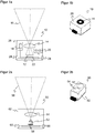
- Figure 1a shows a schematic sectional view of a camera module 10.
- Figure 1b is a supplementary exemplary 3D view.
- the camera module 10 has an image sensor 12 and an optical receiving system 14, which is represented here simply by a simple lens.
- the image sensor 12 is preferably the same for a whole family of cameras in which camera modules 10 are used, or at least has the same connections (pinning) for the simplest interchangeability. Then variants such as monochrome, colored, polarized and the like are also possible. Line cameras or event-based image sensors can also be used as an alternative to standard image sensors.
- the properties of image sensor 12 and receiving optics 14 and their arrangement determine a module viewing area 16 of the camera module. While the module viewing area 16 generally designates the area from which the image sensor 12 can receive and detect light, the depth of field area is also a further property of the module viewing area 16. Because with blurred image data, most of the required evaluations cannot be carried out.
- a focus adjustment 18 shown only schematically, is provided in order to change the depth of field.
- the focus adjustment 18 can be the distance between the image sensor 12 and the receiving optics 14 or directly Change the focal length of the receiving optics 14.
- An electronic focus adjustment 18 is to be preferred, since manual adjustment would be too complex for a large number of camera modules 10.
- a tilting unit 20 serves to laterally shift the module viewing area 16.
- the receiving optics 14 do not have to be physically tilted for this purpose, but rather the tilting unit 20 preferably comprises a suitable actuator system, for example in the form of a moving coil unit or tiltable liquid lens.
- the focus adjustment unit 18 and the tilting unit 20 can also be formed together.
- the position of the image sensor 12 with respect to the receiving optics 14 can be changed for tilting, but this is generally the more cumbersome solution for design reasons.
- a preprocessing unit 22 of the camera module 10 is connected to the image sensor 12.
- Various evaluation modules are conceivable for this, for example an FPGA (Field Programmable Gate Array), a special Al chip or a microcontroller.
- the preprocessing relates to tasks such as segmentation or filtering, in particular geocorrection with the intrinsic camera parameters, which prepares the assembly of partial images of individual camera modules 10 to form an overall image, or generally image processing, which leads to an improved reading result, particularly in code-reading systems.
- An Al chip supports image evaluation processes with neural networks (CNN, Convolutional Neural Networks) and can perform multidimensional matrix multiplications almost in real time. Deviating from the illustration, the preprocessing unit 22 can at least partially be integrated on a chip together with the image sensor 12.
- the camera module 10 communicates with other camera modules or higher-level electronics via electronic interfaces 24.
- Figure 1a shows exemplary interfaces 24 on both sides for a preferred row arrangement of a plurality of camera modules 10.
- the camera module 10 is accommodated in a housing 26.
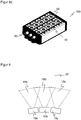
- FIG 2a shows a schematic sectional view and Figure 2b a supplementary exemplary 3D view of an illumination module 50.
- Illumination modules 50 can be combined with camera modules 10 to form a camera with active illumination.
- the basic structure of a lighting module 50 is similar to that of a camera module 10. It comprises a light source 52, for example an LED or a laser, and an illumination optics 54. A module illumination area 56 is thus generated.
- the module lighting area 56 is fixed.
- a variable module lighting area 56 with an actuator system corresponding to the focus adjustment 18 and / or the tilting unit 20 would also be conceivable. Focusing is useful, for example, when the lighting module 50 not only generates brightness, but a structured lighting pattern.
- a lighting control 58 with a lighting driver and other possible functions such as storing module properties, modulating the light source 52 and the like is provided.
- the lighting module 50 communicates with other modules or higher-level electronics via interfaces 60 and is surrounded by a housing 62.
- the three-dimensional view of the Figure 2b shows an embodiment in which an illumination module 50 has two light sources 52 and transmission optics 54, this number being to be understood purely by way of example, but is intended to indicate that multiple light sources 52 per camera module 10 are often required.
- Figure 3 shows a sectional view of a camera 100 with three camera modules 10a-c.
- the internal structure of the camera modules 10a-c became too Figure 1 presented and is no longer shown here for simplicity.
- the modular multi-camera concept naturally also allows a different number of camera modules 10a-c and a different arrangement than their linear arrangement.
- the respective module viewing areas 16a-c complement one another to form a monitoring area 30 of the camera 100.
- the adaptation of module viewing areas 16a-c to different monitoring areas 30 will be described later with reference to FIG Figures 6 to 9 explained in more detail.
- the front end of the camera 100 can preferably include at least one lighting module 50, not shown here.
- the camera modules 10a-c are supplemented with a processor module 70, which is also referred to as a common control and evaluation unit, and an interface module 80.
- the interface module 80 connects the camera modules 10a-c and, if appropriate, further modules such as lighting modules 50 to the processor module 70 and also has interfaces of the camera 100 on the outside.
- the processor module 70 communicates and cooperates with the preprocessing units 22 of the camera modules 10a-c.
- a housing 102 of the camera 100 is preferably produced in an also modular housing concept as an extruded profile in order to represent the different device variants.
- a suitable material is aluminum.
- the plurality of camera modules 10a-c and the monitoring area 30 composed of their module viewing areas 16a-c can serve a wide variety of application requirements.
- Some application examples for the scalable multi-camera 100 are briefly mentioned in the introduction, in particular inspection and measurement in an industrial environment as well as reading codes.
- module viewing areas 16a-c are arranged next to one another or strung together, the overall field of view and thus the monitoring area 30 are enlarged. There is preferably little or no overlap. It is conceivable to combine the individual images of the camera modules 10a-c to form an overall image (image stitching). However, for some applications such as code reading, this is not absolutely necessary. Rather, the data can then also be combined after a first decoder segmentation stage or from several (partial) decodings.
- the focus positions of the camera modules 10a-c can be set individually, a zone focus is possible. There is not the conventional single focus position of the entire camera 100, but camera modules 10a-c focus zone by zone according to individual module viewing areas 16a-c at different distances. In this way, scene elements can also be recorded sharply at widely differing distances outside the depth of field of a single camera module 10a-c.
- An example is the detection of objects or parcels that run side by side on a conveyor belt under the camera 10 and which can have very different heights.
- Redundancy in overlapping areas of the module viewing areas 16a-c can be used in a variety of ways, for example to increase the resolution, for an increased depth of field through complementary focus positions or to increase the image recording frequency.
- An illumination module 50 is then preferably used, which has a pattern generation element in the form of a diffractive optical element or microlens field and illuminates the jointly observed area with a structured pattern in order to ensure enough image features for the stereo correlation and thus the detection of a depth image that is as complete as possible.
- FIGS. 4a-c show some examples of device variants of the camera 100 with different module configurations in a three-dimensional view.
- camera modules 10 and lighting modules 50 that are similar to one another are preferably used, so that no variants are required at the module level.
- a camera module 10 is combined with two lighting modules 50.
- the processor module 70 can be accommodated in a side end cap of the housing 102 instead of under the modules 10, 50.
- the interface module 80 is located in the other side end cap.
- the length of the housing 102 preferably produced as an extruded profile, can be varied in order to accommodate wide camera modules 10 and lighting modules 50.
- Figure 4b showed an embodiment of the camera 100 with six camera modules 10 and nine lighting modules 15 Figure 3 shown, the modules 10, 50 are inserted into a first level and the processor module 70 into a second level of the extruded profile of the housing 102.
- Figure 4c shows an embodiment of the camera 100 with ten camera modules 10 and fifteen lighting modules 50. This corresponds to an extension of the embodiment according to Figure 4b .
- the camera modules 10 are each arranged in a row one after the other.
- the lighting modules 50 also form such rows.
- the combination of camera modules 10 and lighting modules 50 in the same line is conceivable, but technically more challenging. In any case, interconnection and arrangement of the regular rows of the Figures 4a-c differ.
- the signals are each made available by the upstream module 10, 50 and passed on to the downstream module 10, 50 or passed through.
- the signals arrive at the processor module 70 via the interface module 80.
- An additional interface card on the opposite side in the second end cap is not the only one for the smallest camera 100 Figure 4a possible.
- the processor module 70 can be designed for the respective camera 100 in different performance classes or sizes. However, it is also conceivable to continue the modular idea and to build up the respective processor module 70 from combined submodules.
- the interface module 80 and the processor module 70 or submodules thereof can be accommodated in any desired mixed form under the modules 10, 50 or in the side end caps of the housing 102.
- the mutual position of the module viewing areas 16a-c in the camera 100 should generally not be determined directly by the dimensions and distances of the camera modules 10a-c within the camera 100.
- the module viewing areas 16a-c vary when the viewing direction of the camera modules 10a-c is tilted. One way of achieving this is to tilt the entire camera modules 10a-c or to accommodate the camera modules 10a-c or at least the image sensors 12 on one sphere.
- FIG. 5 illustrates where the lateral camera modules 10a, c are tilted outwards by a curved support surface and this results in an overall larger monitoring area 30.
- such an arrangement is technically complex, inflexible and no longer completely modular.
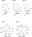
- the Figures 6a-c illustrate how an effective inclination of the camera modules 10 is also possible without physical inclination. This has the great advantage that the contact surface can remain flat. The camera modules 10 accordingly remain physically aligned parallel to one another, the image sensors 12 lie in a flat plane. The camera 100 can thus be manufactured much more cheaply and easily.
- Figure 6a first shows a vertical arrangement without tilting as a reference.
- tilting to the left is achieved by moving the receiving optics 14 to the left and thus tilting the associated module viewing area 16 to the left becomes. Instead, the image sensor 12 could also be shifted to the right.
- the tilting is achieved with an additional optical component 28, for example an optical wedge or prism.
- the tilting is preferably variable in that the tilting unit 20 is equipped with a corresponding actuator system.
- An exemplary embodiment of this is a moving coil unit (3D voice coil actuator), which allows a combination of lens tilt and lateral lens offset in up to five degrees of freedom.
- Another possibility is offered by adaptive lenses, in particular liquid lenses, which are not only adjustable in their focal length by means of additional electrodes, but are also tiltable.
- the lateral movement of image sensor 12 and / or receiving optics 14 for effectively tilting a camera module 10 should not be excluded by such preferred implementations.
- Some forms of tilting a camera module 10 lead to a focus plane no longer arranged in parallel.
- a focus plane no longer arranged in parallel.
- the image sensor 12 can be tilted, preferably in a Scheimpflug arrangement. Depth of field can be a problem, especially with strong tilt angles.
- the effective tilting of camera modules 10 and thus shifting module viewing areas 16 can be used to adapt the monitoring area 30.
- the camera modules 10 or their module viewing areas 16 are preferably aligned with the aid of the tilting unit 20 and possibly the focus adjustment unit 18 such that a monitoring area 30 suitable for the application is created depending on the focus position and the object contour to be recorded.
- Figures 7a-b show the situation for a very close focus position 32 with tilted right camera module 10b.
- the module viewing areas 16a-b move closer together.
- the entire field of view indicated by an arrow or the usable monitoring area 30 can be enlarged by at least partially canceling the tilt or even adjusting a tilt directed away from the other camera module 10a-b.
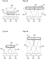
- the Figures 8a-b substantiate the concept using an example with three camera modules 10a-c. With the aid of the tilting unit 20, the tilting in the respective camera modules 10a-c depends on the set focus distance. In the example of the Figures 8a-b only the set focus position is known, in the following example the Figures 9a-b the object distance.
- the Figures 9a-b illustrate the even more favorable case in which even the object distance is known.
- the camera is mounted on a conveyor belt, this corresponds to the object height.
- the object width is preferably even known.
- the tilting and thus the module viewing areas 16a-c can be aligned in a very targeted manner to the object 34 in order to optimize the object 34 and in particular Cover with maximum overlap and thus record with maximum sharpness, resolution and / or speed, depending on what the application wants.
- Figure 9a it is known that the object 34 is located at a relatively close distance.
- the camera modules 10a-c are tilted to a great extent in order to capture the object 34 in its full width without gaps and in the depth of field.
- a more complex object contour with locally different distances from the camera can also be recorded, or alternatively, several objects of different geometry can be recorded simultaneously.
- zones of the object contour or of the objects are formed, which can be recorded with the same focus setting.
- the camera modules 10a-b are now focused zone by zone and their module viewing areas 16a-c are aligned with the associated zone.
- the Figures 8 and 9 can then be understood as a partial view of that partial selection of camera modules 10a-b which are responsible for a zone.
- An additional sensor can be used to detect the focus position or the object geometry.
- a simple height can be measured with a light barrier or a light grid, more complex geometries with a laser scanner or a 3D camera.
- a sensor In applications on conveyor belts, such a sensor is conventionally arranged upstream. The geometry information is transmitted to the camera and assigned via the conveyor belt speed.
- Three-dimensional image data do not necessarily have to be used for the setting of module viewing areas 16a-c, but are also the detection size sought, depending on the application.
- the camera 100 can capture three-dimensional image data based on the stereoscopic principle from the overlapping recordings of at least two camera modules.
- a camera module 10 with a suitable lighting module 50 can be further developed into a light propagation time module.
- the lighting module 50 then generates a modulated light signal, and from the modulation the light propagation time module uses a phase or pulse method to determine the light propagation time and thus a distance value.
- camera modules 10, lighting modules 50 were also specifically presented with structured or modulated lighting.
- Further modules are conceivable, for example a target laser module which displays the monitoring area 30, module viewing areas 16 or a reading field within the monitoring area as a laser point, cross or other pattern, or a visual feedback module which makes the set focus position or a detection result visible, for example by means of a red one or green light for a code that has not been read or has been read successfully (NoRead / GoodRead).
Landscapes
- Engineering & Computer Science (AREA)
- Multimedia (AREA)
- Signal Processing (AREA)
- Physics & Mathematics (AREA)
- General Physics & Mathematics (AREA)
- Theoretical Computer Science (AREA)
- Health & Medical Sciences (AREA)
- Electromagnetism (AREA)
- General Health & Medical Sciences (AREA)
- Toxicology (AREA)
- Artificial Intelligence (AREA)
- Computer Vision & Pattern Recognition (AREA)
- Human Computer Interaction (AREA)
- Computing Systems (AREA)
- Studio Devices (AREA)
- Length Measuring Devices By Optical Means (AREA)
- Closed-Circuit Television Systems (AREA)
Applications Claiming Priority (1)
| Application Number | Priority Date | Filing Date | Title |
|---|---|---|---|
| DE102019101490.5A DE102019101490A1 (de) | 2019-01-22 | 2019-01-22 | Modulare Kameravorrichtung und Verfahren zur optischen Erfassung |
Publications (3)
| Publication Number | Publication Date |
|---|---|
| EP3687155A1 true EP3687155A1 (fr) | 2020-07-29 |
| EP3687155A8 EP3687155A8 (fr) | 2020-09-02 |
| EP3687155B1 EP3687155B1 (fr) | 2021-10-06 |
Family
ID=69143470
Family Applications (1)
| Application Number | Title | Priority Date | Filing Date |
|---|---|---|---|
| EP20150518.7A Active EP3687155B1 (fr) | 2019-01-22 | 2020-01-07 | Dispositif modulaire de caméra et procédé de détection optique |
Country Status (4)
| Country | Link |
|---|---|
| US (1) | US20200234018A1 (fr) |
| EP (1) | EP3687155B1 (fr) |
| DE (1) | DE102019101490A1 (fr) |
| DK (1) | DK3687155T3 (fr) |
Cited By (1)
| Publication number | Priority date | Publication date | Assignee | Title |
|---|---|---|---|---|
| EP4571666A1 (fr) * | 2023-12-14 | 2025-06-18 | Sick Ag | Système de caméra pour un dispositif de reconnaissance d'étiquettes |
Families Citing this family (2)
| Publication number | Priority date | Publication date | Assignee | Title |
|---|---|---|---|---|
| DE102019126419A1 (de) * | 2019-05-08 | 2020-11-12 | Docter Optics Se | Vorrichtung zum optischen Abbilden von Merkmalen einer Hand |
| IT202000029153A1 (it) * | 2020-12-01 | 2022-06-01 | Friulexpress S R L | Apparato di ispezione ottica |
Citations (8)
| Publication number | Priority date | Publication date | Assignee | Title |
|---|---|---|---|---|
| US20110109748A1 (en) | 2009-11-12 | 2011-05-12 | Hon Hai Precision Industry Co., Ltd. | Camera array |
| WO2012047216A1 (fr) * | 2010-10-06 | 2012-04-12 | Hewlett-Packard Development Company, L.P. | Systèmes et procédés pour acquérir et traiter des données d'image produites par des ensembles de caméras |
| EP2546776B1 (fr) | 2011-07-11 | 2013-06-12 | Sick Ag | Lecteur de code basé sur un appareil de prise de vue et son procédé de fabrication ajustée |
| DE102014114506A1 (de) | 2014-10-07 | 2016-04-07 | Sick Ag | Kamera zur Montage an einer Fördereinrichtung und Verfahren zur Inspektion oder Identifikation |
| US9497380B1 (en) * | 2013-02-15 | 2016-11-15 | Red.Com, Inc. | Dense field imaging |
| DE102015215833A1 (de) * | 2015-08-19 | 2017-02-23 | Fraunhofer-Gesellschaft zur Förderung der angewandten Forschung e.V. | Multiaperturabbildungsvorrichtung mit Optiksubstrat |
| US9940494B2 (en) | 2016-05-31 | 2018-04-10 | Sick Ag | RFID reading apparatus for shelf occupancy detection |
| EP3388860A1 (fr) * | 2017-04-12 | 2018-10-17 | Sick AG | Caméra pour l'évaluation du temps de propagation de la lumière 3d et procédé de détection de données d'image tridimensionnelles |
Family Cites Families (13)
| Publication number | Priority date | Publication date | Assignee | Title |
|---|---|---|---|---|
| EP2153641B2 (fr) * | 2007-04-13 | 2021-10-27 | Ari M. Presler | Système de caméra cinématographique numérique pour enregistrer, éditer et visualiser des images |
| US9871999B2 (en) * | 2013-07-05 | 2018-01-16 | Flir Systems, Inc. | Modular camera monitoring systems and methods |
| DK2860553T3 (en) * | 2013-10-10 | 2016-02-01 | Sick Ag | Optoelectronic sensor and method for detecting object information |
| DE102014105759A1 (de) * | 2014-04-24 | 2015-10-29 | Sick Ag | Kamera und Verfahren zur Erfassung eines bewegten Stroms von Objekten |
| CN105187697B (zh) * | 2015-08-04 | 2019-12-31 | 宁波舜宇光电信息有限公司 | 多镜头摄像模组连体支架和多镜头摄像模组及其应用 |
| US10033917B1 (en) * | 2015-11-13 | 2018-07-24 | Apple Inc. | Dynamic optical shift/tilt lens |
| DE102016122712B3 (de) * | 2016-11-24 | 2017-11-23 | Sick Ag | Optoelektronischer Sensor und Verfahren zur Erfassung von Objektinformationen |
| US11331796B2 (en) * | 2018-02-12 | 2022-05-17 | Brain Corporation | Autonomous multi-tasking modular robotic system |
| KR102486426B1 (ko) * | 2018-02-23 | 2023-01-09 | 엘지이노텍 주식회사 | 카메라 모듈 |
| CN110312058B (zh) * | 2018-03-27 | 2020-09-11 | 华为技术有限公司 | 三摄像头设备和终端设备 |
| KR102799830B1 (ko) * | 2018-09-05 | 2025-04-28 | 엘지이노텍 주식회사 | 카메라 모듈 |
| US11412136B2 (en) * | 2018-12-07 | 2022-08-09 | Samsung Electronics Co., Ltd. | Apparatus and method for operating multiple cameras for digital photography |
| US11737627B2 (en) * | 2020-10-03 | 2023-08-29 | Viabot Inc. | Methods for setting and programming zoning for use by autonomous modular robots |
-
2019
- 2019-01-22 DE DE102019101490.5A patent/DE102019101490A1/de not_active Withdrawn
-
2020
- 2020-01-07 DK DK20150518.7T patent/DK3687155T3/da active
- 2020-01-07 EP EP20150518.7A patent/EP3687155B1/fr active Active
- 2020-01-21 US US16/747,813 patent/US20200234018A1/en not_active Abandoned
Patent Citations (9)
| Publication number | Priority date | Publication date | Assignee | Title |
|---|---|---|---|---|
| US20110109748A1 (en) | 2009-11-12 | 2011-05-12 | Hon Hai Precision Industry Co., Ltd. | Camera array |
| WO2012047216A1 (fr) * | 2010-10-06 | 2012-04-12 | Hewlett-Packard Development Company, L.P. | Systèmes et procédés pour acquérir et traiter des données d'image produites par des ensembles de caméras |
| EP2546776B1 (fr) | 2011-07-11 | 2013-06-12 | Sick Ag | Lecteur de code basé sur un appareil de prise de vue et son procédé de fabrication ajustée |
| US9497380B1 (en) * | 2013-02-15 | 2016-11-15 | Red.Com, Inc. | Dense field imaging |
| DE102014114506A1 (de) | 2014-10-07 | 2016-04-07 | Sick Ag | Kamera zur Montage an einer Fördereinrichtung und Verfahren zur Inspektion oder Identifikation |
| DE102015215833A1 (de) * | 2015-08-19 | 2017-02-23 | Fraunhofer-Gesellschaft zur Förderung der angewandten Forschung e.V. | Multiaperturabbildungsvorrichtung mit Optiksubstrat |
| US9940494B2 (en) | 2016-05-31 | 2018-04-10 | Sick Ag | RFID reading apparatus for shelf occupancy detection |
| EP3388860A1 (fr) * | 2017-04-12 | 2018-10-17 | Sick AG | Caméra pour l'évaluation du temps de propagation de la lumière 3d et procédé de détection de données d'image tridimensionnelles |
| DE102017107903A1 (de) | 2017-04-12 | 2018-10-18 | Sick Ag | 3D-Lichtlaufzeitkamera und Verfahren zur Erfassung dreidimensionaler Bilddaten |
Cited By (1)
| Publication number | Priority date | Publication date | Assignee | Title |
|---|---|---|---|---|
| EP4571666A1 (fr) * | 2023-12-14 | 2025-06-18 | Sick Ag | Système de caméra pour un dispositif de reconnaissance d'étiquettes |
Also Published As
| Publication number | Publication date |
|---|---|
| DE102019101490A1 (de) | 2020-07-23 |
| US20200234018A1 (en) | 2020-07-23 |
| EP3687155A8 (fr) | 2020-09-02 |
| EP3687155B1 (fr) | 2021-10-06 |
| DK3687155T3 (da) | 2021-11-15 |
Similar Documents
| Publication | Publication Date | Title |
|---|---|---|
| EP2693363B1 (fr) | Système de caméra et procédé de détermination d'un flux d'objets | |
| EP2546776B1 (fr) | Lecteur de code basé sur un appareil de prise de vue et son procédé de fabrication ajustée | |
| EP2937810B1 (fr) | Système de caméra et procédé de détermination d'un flux mobile d'objets | |
| EP3729137B1 (fr) | Système lidar à impulsions multiples pour la détection multidimensionnelle d'objets | |
| EP3663963B1 (fr) | Lecture de codes optiques | |
| DE102013110615B3 (de) | 3D-Kamera nach dem Stereoskopieprinzip und Verfahren zum Erfassen von Tiefenkarten | |
| EP2693362B1 (fr) | Système de détection destiné à être monté sur une bande de transport | |
| EP3327611B1 (fr) | Dispositif de détection et procédé de détection d'un objet dotés d'une multitude de capteurs optoélectroniques | |
| EP2924477B1 (fr) | Dispositif optoélectronique et procédé de détection d'informations d'objets | |
| EP4075394B1 (fr) | Détection d'un flux mobile d'objets | |
| EP2620894B1 (fr) | Capteur optoélectronique et procédé de détection d'informations d'objets | |
| EP3687155B1 (fr) | Dispositif modulaire de caméra et procédé de détection optique | |
| EP3383026B1 (fr) | Caméra et procédé de détection d'objets se déplaçant vers la caméra dans un dispositif de transport | |
| EP2863253B1 (fr) | Dispositif de déviation et d'élargissement d'un champ de vision | |
| DE102014114506B4 (de) | Kamera zur Montage an einer Fördereinrichtung und Verfahren zur Inspektion oder Identifikation | |
| EP2924973A2 (fr) | Dispositif optoélectronique et son procédé de réglage | |
| EP3812953A1 (fr) | Lecteur de codes et procédé de lecture des codes optiques | |
| EP2950519B1 (fr) | Caméra et procédé de capture de données d'image | |
| EP3693927B1 (fr) | Alignement d'une caméra à balayage linéaire avec des triangles comme cibles d'alignement. | |
| DE202013009198U1 (de) | Vorrichtung zum Umlenken und zur Verbreiterung des Sichtbereichs | |
| EP3591567A1 (fr) | Capteur optoélectronique et procédé de détection optique répétitive d'objets à distance de l'objet différente | |
| DE102020113183A1 (de) | Kamera und Verfahren zur Erfassung von bewegten Objekten | |
| DE102006017337A1 (de) | Verfahren zur optischen Erfassung von bewegten Objekten und Vorrichtung | |
| EP3736603B1 (fr) | Capteur optoélectronique et procédé de surveillance d'une zone de surveillance | |
| DE102021100947B4 (de) | Kameravorrichtung und Verfahren zur Erfassung eines Objekts |
Legal Events
| Date | Code | Title | Description |
|---|---|---|---|
| PUAI | Public reference made under article 153(3) epc to a published international application that has entered the european phase |
Free format text: ORIGINAL CODE: 0009012 |
|
| STAA | Information on the status of an ep patent application or granted ep patent |
Free format text: STATUS: THE APPLICATION HAS BEEN PUBLISHED |
|
| STAA | Information on the status of an ep patent application or granted ep patent |
Free format text: STATUS: REQUEST FOR EXAMINATION WAS MADE |
|
| AK | Designated contracting states |
Kind code of ref document: A1 Designated state(s): AL AT BE BG CH CY CZ DE DK EE ES FI FR GB GR HR HU IE IS IT LI LT LU LV MC MK MT NL NO PL PT RO RS SE SI SK SM TR |
|
| AX | Request for extension of the european patent |
Extension state: BA ME |
|
| STAA | Information on the status of an ep patent application or granted ep patent |
Free format text: STATUS: EXAMINATION IS IN PROGRESS |
|
| 17P | Request for examination filed |
Effective date: 20200626 |
|
| RBV | Designated contracting states (corrected) |
Designated state(s): AL AT BE BG CH CY CZ DE DK EE ES FI FR GB GR HR HU IE IS IT LI LT LU LV MC MK MT NL NO PL PT RO RS SE SI SK SM TR |
|
| 17Q | First examination report despatched |
Effective date: 20200803 |
|
| GRAP | Despatch of communication of intention to grant a patent |
Free format text: ORIGINAL CODE: EPIDOSNIGR1 |
|
| STAA | Information on the status of an ep patent application or granted ep patent |
Free format text: STATUS: GRANT OF PATENT IS INTENDED |
|
| RIC1 | Information provided on ipc code assigned before grant |
Ipc: H04N 5/225 20060101AFI20210702BHEP Ipc: H04N 5/232 20060101ALI20210702BHEP Ipc: G03B 5/00 20210101ALI20210702BHEP Ipc: G03B 17/02 20210101ALI20210702BHEP Ipc: G03B 37/04 20210101ALI20210702BHEP Ipc: H04N 5/247 20060101ALI20210702BHEP Ipc: G02B 3/14 20060101ALI20210702BHEP Ipc: G02B 3/12 20060101ALI20210702BHEP Ipc: G03B 3/10 20210101ALI20210702BHEP |
|
| GRAS | Grant fee paid |
Free format text: ORIGINAL CODE: EPIDOSNIGR3 |
|
| INTG | Intention to grant announced |
Effective date: 20210727 |
|
| GRAA | (expected) grant |
Free format text: ORIGINAL CODE: 0009210 |
|
| STAA | Information on the status of an ep patent application or granted ep patent |
Free format text: STATUS: THE PATENT HAS BEEN GRANTED |
|
| AK | Designated contracting states |
Kind code of ref document: B1 Designated state(s): AL AT BE BG CH CY CZ DE DK EE ES FI FR GB GR HR HU IE IS IT LI LT LU LV MC MK MT NL NO PL PT RO RS SE SI SK SM TR |
|
| REG | Reference to a national code |
Ref country code: GB Ref legal event code: FG4D Free format text: NOT ENGLISH |
|
| REG | Reference to a national code |
Ref country code: CH Ref legal event code: EP Ref country code: AT Ref legal event code: REF Ref document number: 1437243 Country of ref document: AT Kind code of ref document: T Effective date: 20211015 |
|
| REG | Reference to a national code |
Ref country code: IE Ref legal event code: FG4D Free format text: LANGUAGE OF EP DOCUMENT: GERMAN |
|
| REG | Reference to a national code |
Ref country code: DE Ref legal event code: R096 Ref document number: 502020000224 Country of ref document: DE |
|
| REG | Reference to a national code |
Ref country code: DK Ref legal event code: T3 Effective date: 20211109 |
|
| REG | Reference to a national code |
Ref country code: SE Ref legal event code: TRGR |
|
| REG | Reference to a national code |
Ref country code: NL Ref legal event code: FP |
|
| REG | Reference to a national code |
Ref country code: LT Ref legal event code: MG9D |
|
| PG25 | Lapsed in a contracting state [announced via postgrant information from national office to epo] |
Ref country code: RS Free format text: LAPSE BECAUSE OF FAILURE TO SUBMIT A TRANSLATION OF THE DESCRIPTION OR TO PAY THE FEE WITHIN THE PRESCRIBED TIME-LIMIT Effective date: 20211006 Ref country code: LT Free format text: LAPSE BECAUSE OF FAILURE TO SUBMIT A TRANSLATION OF THE DESCRIPTION OR TO PAY THE FEE WITHIN THE PRESCRIBED TIME-LIMIT Effective date: 20211006 Ref country code: FI Free format text: LAPSE BECAUSE OF FAILURE TO SUBMIT A TRANSLATION OF THE DESCRIPTION OR TO PAY THE FEE WITHIN THE PRESCRIBED TIME-LIMIT Effective date: 20211006 Ref country code: BG Free format text: LAPSE BECAUSE OF FAILURE TO SUBMIT A TRANSLATION OF THE DESCRIPTION OR TO PAY THE FEE WITHIN THE PRESCRIBED TIME-LIMIT Effective date: 20220106 |
|
| PG25 | Lapsed in a contracting state [announced via postgrant information from national office to epo] |
Ref country code: IS Free format text: LAPSE BECAUSE OF FAILURE TO SUBMIT A TRANSLATION OF THE DESCRIPTION OR TO PAY THE FEE WITHIN THE PRESCRIBED TIME-LIMIT Effective date: 20220206 Ref country code: PT Free format text: LAPSE BECAUSE OF FAILURE TO SUBMIT A TRANSLATION OF THE DESCRIPTION OR TO PAY THE FEE WITHIN THE PRESCRIBED TIME-LIMIT Effective date: 20220207 Ref country code: PL Free format text: LAPSE BECAUSE OF FAILURE TO SUBMIT A TRANSLATION OF THE DESCRIPTION OR TO PAY THE FEE WITHIN THE PRESCRIBED TIME-LIMIT Effective date: 20211006 Ref country code: NO Free format text: LAPSE BECAUSE OF FAILURE TO SUBMIT A TRANSLATION OF THE DESCRIPTION OR TO PAY THE FEE WITHIN THE PRESCRIBED TIME-LIMIT Effective date: 20220106 Ref country code: LV Free format text: LAPSE BECAUSE OF FAILURE TO SUBMIT A TRANSLATION OF THE DESCRIPTION OR TO PAY THE FEE WITHIN THE PRESCRIBED TIME-LIMIT Effective date: 20211006 Ref country code: HR Free format text: LAPSE BECAUSE OF FAILURE TO SUBMIT A TRANSLATION OF THE DESCRIPTION OR TO PAY THE FEE WITHIN THE PRESCRIBED TIME-LIMIT Effective date: 20211006 Ref country code: GR Free format text: LAPSE BECAUSE OF FAILURE TO SUBMIT A TRANSLATION OF THE DESCRIPTION OR TO PAY THE FEE WITHIN THE PRESCRIBED TIME-LIMIT Effective date: 20220107 Ref country code: ES Free format text: LAPSE BECAUSE OF FAILURE TO SUBMIT A TRANSLATION OF THE DESCRIPTION OR TO PAY THE FEE WITHIN THE PRESCRIBED TIME-LIMIT Effective date: 20211006 |
|
| REG | Reference to a national code |
Ref country code: DE Ref legal event code: R097 Ref document number: 502020000224 Country of ref document: DE |
|
| PG25 | Lapsed in a contracting state [announced via postgrant information from national office to epo] |
Ref country code: SM Free format text: LAPSE BECAUSE OF FAILURE TO SUBMIT A TRANSLATION OF THE DESCRIPTION OR TO PAY THE FEE WITHIN THE PRESCRIBED TIME-LIMIT Effective date: 20211006 Ref country code: SK Free format text: LAPSE BECAUSE OF FAILURE TO SUBMIT A TRANSLATION OF THE DESCRIPTION OR TO PAY THE FEE WITHIN THE PRESCRIBED TIME-LIMIT Effective date: 20211006 Ref country code: RO Free format text: LAPSE BECAUSE OF FAILURE TO SUBMIT A TRANSLATION OF THE DESCRIPTION OR TO PAY THE FEE WITHIN THE PRESCRIBED TIME-LIMIT Effective date: 20211006 Ref country code: EE Free format text: LAPSE BECAUSE OF FAILURE TO SUBMIT A TRANSLATION OF THE DESCRIPTION OR TO PAY THE FEE WITHIN THE PRESCRIBED TIME-LIMIT Effective date: 20211006 Ref country code: CZ Free format text: LAPSE BECAUSE OF FAILURE TO SUBMIT A TRANSLATION OF THE DESCRIPTION OR TO PAY THE FEE WITHIN THE PRESCRIBED TIME-LIMIT Effective date: 20211006 |
|
| PLBE | No opposition filed within time limit |
Free format text: ORIGINAL CODE: 0009261 |
|
| STAA | Information on the status of an ep patent application or granted ep patent |
Free format text: STATUS: NO OPPOSITION FILED WITHIN TIME LIMIT |
|
| PG25 | Lapsed in a contracting state [announced via postgrant information from national office to epo] |
Ref country code: MC Free format text: LAPSE BECAUSE OF FAILURE TO SUBMIT A TRANSLATION OF THE DESCRIPTION OR TO PAY THE FEE WITHIN THE PRESCRIBED TIME-LIMIT Effective date: 20211006 |
|
| 26N | No opposition filed |
Effective date: 20220707 |
|
| PG25 | Lapsed in a contracting state [announced via postgrant information from national office to epo] |
Ref country code: LU Free format text: LAPSE BECAUSE OF NON-PAYMENT OF DUE FEES Effective date: 20220107 Ref country code: AL Free format text: LAPSE BECAUSE OF FAILURE TO SUBMIT A TRANSLATION OF THE DESCRIPTION OR TO PAY THE FEE WITHIN THE PRESCRIBED TIME-LIMIT Effective date: 20211006 |
|
| REG | Reference to a national code |
Ref country code: DE Ref legal event code: R079 Ref document number: 502020000224 Country of ref document: DE Free format text: PREVIOUS MAIN CLASS: H04N0005225000 Ipc: H04N0023000000 |
|
| PG25 | Lapsed in a contracting state [announced via postgrant information from national office to epo] |
Ref country code: SI Free format text: LAPSE BECAUSE OF FAILURE TO SUBMIT A TRANSLATION OF THE DESCRIPTION OR TO PAY THE FEE WITHIN THE PRESCRIBED TIME-LIMIT Effective date: 20211006 |
|
| PG25 | Lapsed in a contracting state [announced via postgrant information from national office to epo] |
Ref country code: IE Free format text: LAPSE BECAUSE OF NON-PAYMENT OF DUE FEES Effective date: 20220107 |
|
| PGFP | Annual fee paid to national office [announced via postgrant information from national office to epo] |
Ref country code: IT Payment date: 20230131 Year of fee payment: 4 |
|
| PG25 | Lapsed in a contracting state [announced via postgrant information from national office to epo] |
Ref country code: MK Free format text: LAPSE BECAUSE OF FAILURE TO SUBMIT A TRANSLATION OF THE DESCRIPTION OR TO PAY THE FEE WITHIN THE PRESCRIBED TIME-LIMIT Effective date: 20211006 Ref country code: CY Free format text: LAPSE BECAUSE OF FAILURE TO SUBMIT A TRANSLATION OF THE DESCRIPTION OR TO PAY THE FEE WITHIN THE PRESCRIBED TIME-LIMIT Effective date: 20211006 |
|
| PG25 | Lapsed in a contracting state [announced via postgrant information from national office to epo] |
Ref country code: HU Free format text: LAPSE BECAUSE OF FAILURE TO SUBMIT A TRANSLATION OF THE DESCRIPTION OR TO PAY THE FEE WITHIN THE PRESCRIBED TIME-LIMIT; INVALID AB INITIO Effective date: 20200107 |
|
| PG25 | Lapsed in a contracting state [announced via postgrant information from national office to epo] |
Ref country code: MT Free format text: LAPSE BECAUSE OF FAILURE TO SUBMIT A TRANSLATION OF THE DESCRIPTION OR TO PAY THE FEE WITHIN THE PRESCRIBED TIME-LIMIT Effective date: 20211006 |
|
| PG25 | Lapsed in a contracting state [announced via postgrant information from national office to epo] |
Ref country code: TR Free format text: LAPSE BECAUSE OF FAILURE TO SUBMIT A TRANSLATION OF THE DESCRIPTION OR TO PAY THE FEE WITHIN THE PRESCRIBED TIME-LIMIT Effective date: 20211006 |
|
| REG | Reference to a national code |
Ref country code: CH Ref legal event code: U11 Free format text: ST27 STATUS EVENT CODE: U-0-0-U10-U11 (AS PROVIDED BY THE NATIONAL OFFICE) Effective date: 20260201 |
|
| PGFP | Annual fee paid to national office [announced via postgrant information from national office to epo] |
Ref country code: NL Payment date: 20260121 Year of fee payment: 7 |
|
| PGFP | Annual fee paid to national office [announced via postgrant information from national office to epo] |
Ref country code: SE Payment date: 20260121 Year of fee payment: 7 |
|
| PGFP | Annual fee paid to national office [announced via postgrant information from national office to epo] |
Ref country code: GB Payment date: 20260122 Year of fee payment: 7 |
|
| PGFP | Annual fee paid to national office [announced via postgrant information from national office to epo] |
Ref country code: DE Payment date: 20260120 Year of fee payment: 7 Ref country code: DK Payment date: 20260115 Year of fee payment: 7 |
|
| PGFP | Annual fee paid to national office [announced via postgrant information from national office to epo] |
Ref country code: AT Payment date: 20260119 Year of fee payment: 7 |
|
| PGFP | Annual fee paid to national office [announced via postgrant information from national office to epo] |
Ref country code: BE Payment date: 20260121 Year of fee payment: 7 |
|
| PGFP | Annual fee paid to national office [announced via postgrant information from national office to epo] |
Ref country code: FR Payment date: 20260128 Year of fee payment: 7 |
|
| PGFP | Annual fee paid to national office [announced via postgrant information from national office to epo] |
Ref country code: CH Payment date: 20260201 Year of fee payment: 7 |