EP3687191A1 - Capteur ultrasonore - Google Patents
Capteur ultrasonore Download PDFInfo
- Publication number
- EP3687191A1 EP3687191A1 EP18858712.5A EP18858712A EP3687191A1 EP 3687191 A1 EP3687191 A1 EP 3687191A1 EP 18858712 A EP18858712 A EP 18858712A EP 3687191 A1 EP3687191 A1 EP 3687191A1
- Authority
- EP
- European Patent Office
- Prior art keywords
- internal space
- bottom plate
- ultrasonic sensor
- case
- longitudinal direction
- Prior art date
- Legal status (The legal status is an assumption and is not a legal conclusion. Google has not performed a legal analysis and makes no representation as to the accuracy of the status listed.)
- Granted
Links
Images





Classifications
-
- G—PHYSICS
- G01—MEASURING; TESTING
- G01S—RADIO DIRECTION-FINDING; RADIO NAVIGATION; DETERMINING DISTANCE OR VELOCITY BY USE OF RADIO WAVES; LOCATING OR PRESENCE-DETECTING BY USE OF THE REFLECTION OR RERADIATION OF RADIO WAVES; ANALOGOUS ARRANGEMENTS USING OTHER WAVES
- G01S7/00—Details of systems according to groups G01S13/00, G01S15/00, G01S17/00
- G01S7/52—Details of systems according to groups G01S13/00, G01S15/00, G01S17/00 of systems according to group G01S15/00
- G01S7/521—Constructional features
-
- G—PHYSICS
- G01—MEASURING; TESTING
- G01S—RADIO DIRECTION-FINDING; RADIO NAVIGATION; DETERMINING DISTANCE OR VELOCITY BY USE OF RADIO WAVES; LOCATING OR PRESENCE-DETECTING BY USE OF THE REFLECTION OR RERADIATION OF RADIO WAVES; ANALOGOUS ARRANGEMENTS USING OTHER WAVES
- G01S15/00—Systems using the reflection or reradiation of acoustic waves, e.g. sonar systems
- G01S15/88—Sonar systems specially adapted for specific applications
- G01S15/93—Sonar systems specially adapted for specific applications for anti-collision purposes
- G01S15/931—Sonar systems specially adapted for specific applications for anti-collision purposes of land vehicles
-
- H—ELECTRICITY
- H04—ELECTRIC COMMUNICATION TECHNIQUE
- H04R—LOUDSPEAKERS, MICROPHONES, GRAMOPHONE PICK-UPS OR LIKE ACOUSTIC ELECTROMECHANICAL TRANSDUCERS; ELECTRIC HEARING AIDS; PUBLIC ADDRESS SYSTEMS
- H04R17/00—Piezoelectric transducers; Electrostrictive transducers
-
- G—PHYSICS
- G01—MEASURING; TESTING
- G01S—RADIO DIRECTION-FINDING; RADIO NAVIGATION; DETERMINING DISTANCE OR VELOCITY BY USE OF RADIO WAVES; LOCATING OR PRESENCE-DETECTING BY USE OF THE REFLECTION OR RERADIATION OF RADIO WAVES; ANALOGOUS ARRANGEMENTS USING OTHER WAVES
- G01S15/00—Systems using the reflection or reradiation of acoustic waves, e.g. sonar systems
- G01S15/88—Sonar systems specially adapted for specific applications
- G01S15/93—Sonar systems specially adapted for specific applications for anti-collision purposes
- G01S15/931—Sonar systems specially adapted for specific applications for anti-collision purposes of land vehicles
- G01S2015/937—Sonar systems specially adapted for specific applications for anti-collision purposes of land vehicles sensor installation details
- G01S2015/938—Sonar systems specially adapted for specific applications for anti-collision purposes of land vehicles sensor installation details in the bumper area
Definitions
- the present invention relates to an ultrasonic sensor.
- the ultrasonic sensor is mounted, for example, on the rear of a vehicle and used as a back sonar.
- the ultrasonic sensor transmits ultrasonic waves backward from the vehicle, and then receives the ultrasonic waves reflected and returned from an obstacle behind the vehicle.
- distance information can be determined.
- the distance information described above can be used to control the driving of the vehicle.
- An exemplary ultrasonic sensor that can be used for such purposes is described in Japanese Unexamined Patent Application Publication No. 2002-209294 (Patent Document 1).
- Patent Document 1 Japanese Unexamined Patent Application Publication No. 2002-209294
- a lack of vertical directivity in the ultrasonic sensor may cause erroneous detection of an unwanted object.
- a further improvement in vertical directivity is required.
- the appearance or design of the ultrasonic sensor mounted, for example, on a vehicle is also an issue to be discussed.
- an object of the present invention is to improve vertical directivity without sacrificing the design of the ultrasonic sensor mounted, for example, on a vehicle.
- an ultrasonic sensor based on the present invention includes a cylindrical case having a bottom plate, and a piezoelectric vibrating element mounted on the bottom plate inside the case.
- the case has an internal space that is a recess extending downward toward the bottom plate. When viewed in a direction perpendicular to the bottom plate, the internal space is of a shape having a longitudinal direction parallel to the bottom plate.
- the case includes a first portion and a second portion. The first portion has a cylindrical shape extending from the bottom plate in the direction perpendicular to the bottom plate, and has a first length which is an outside diameter along the longitudinal direction.
- the second portion is disposed on a side of the first portion remote from the bottom plate, has a cylindrical shape concentric with the first portion, and has a second length which is an outside diameter along the longitudinal direction and is greater than the first length.
- a maximum length of a part of the internal space inside the second portion along the longitudinal direction is greater than a maximum length of a part of the internal space inside the first portion along the longitudinal direction.
- the present invention makes it possible to improve vertical directivity without sacrificing the design of the ultrasonic sensor mounted, for example, on a vehicle.
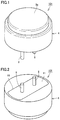
- Fig. 1 illustrates an outer appearance of an ultrasonic sensor 101 according to the present embodiment.
- the ultrasonic sensor 101 includes a case 4 and two external terminals 8 protruding from the case 4.
- the case 4 has a front surface 3a.
- the front surface 3a is, for example, circular in shape.
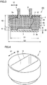
- Fig. 2 illustrates a back side of the ultrasonic sensor 101.
- the case 4 has an opening 19.
- the opening 19 is closed by a lid 11.
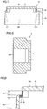
- Fig. 3 is a cross-sectional view of the ultrasonic sensor 101.
- the two external terminals 8 are positioned to protrude out of a filling material 12.
- the two external terminals 8 each pass through the lid 11.
- the case 4 is formed, for example, of metal.
- the case 4 is formed, for example, in an integrated manner.
- the case 4 has a bottom plate 3, and the front surface 3a visible in Fig. 1 includes the outer surface of the bottom plate 3.
- the ultrasonic sensor 101 includes the case 4 cylindrically shaped and having the bottom plate 3, and a piezoelectric vibrating element 7 mounted on the bottom plate 3 inside the case 4.
- the case 4 has an internal space 20 which is a recess extending downward toward the bottom plate.
- the internal space 20 is filled with the filling material 12.
- the internal space 20 is closed by the lid 11.
- the lid 11 is formed of, for example, an insulator.
- the internal space 20 is filled with the filling material 12.
- one of the two external terminals 8 is electrically connected to the case 4 by a lead wire 9a, and the other of the two external terminals 8 is electrically connected to the piezoelectric vibrating element 7 by a lead wire 9b.
- the piezoelectric vibrating element 7 actually includes two electrodes. Of the two electrodes of the piezoelectric vibrating element 7, one is electrically connected to the lead wire 9b, and the other is electrically connected to the bottom plate 3 of the case 4.
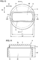
- Fig. 4 illustrates the case 4 taken out independently.
- Fig. 5 illustrates the case 4 as viewed from the front surface 3a.
- the internal space 20 is of a shape having a longitudinal direction 91 parallel to the bottom plate 3.
- Fig. 6 illustrates the case 4 as viewed from the opening 19.
- Fig. 7 is a cross-sectional view as viewed in the direction of arrow VII-VII in Fig. 6 .
- Fig. 8 is a cross-sectional view as viewed in the direction of arrow VIII-VIII in Fig. 6 .
- the case 4 includes a first portion 41 and a second portion 42.
- the first portion 41 has a cylindrical shape extending from the bottom plate 3 in the direction 90 perpendicular to the bottom plate 3, and has a first length D1 which is an outside diameter along the longitudinal direction 91.
- the second portion 42 is disposed on a side of the first portion 41 remote from the bottom plate 3, has a cylindrical shape concentric with the first portion 41, and has a second length D2 which is an outside diameter along the longitudinal direction 91 and is greater than the first length D1.
- a maximum length L2 of a part of the internal space 20 inside the second portion 42 along the longitudinal direction 91 is greater than a maximum length L1 of a part of the internal space 20 inside the first portion 41 along the longitudinal direction 91.
- the bottom plate 3 serves as a vibrating plate.
- the piezoelectric vibrating element 7 vibrates in response to an electric signal applied to the piezoelectric vibrating element 7. Vibration produced by the piezoelectric vibrating element 7 vibrates the bottom plate 3 and sends out ultrasonic waves from the front surface 3a. Ultrasonic waves coming from outside onto the front surface 3a vibrate the bottom plate 3. By the piezoelectric vibrating element 7, this vibration can be detected as an electric signal.
- the present embodiment can improve the vertical directivity provided by the conventional structure. That is, the present embodiment can narrow the angular range which allows high-sensitivity sensing. The reasons for this will be described in detail below.
- L1 is preferably increased as much as possible.
- L1 is a dimension obtained by subtracting a value twice the thickness of the outer wall of the first portion 41 from D1, which is the diameter of the first portion 41 along the longitudinal direction 91. This means that the vertical directivity is dependent on the outer shape of the first portion 41.
- the outer shape of the first portion 41 cannot be expanded due to limitations associated with, for example, space for installing the ultrasonic sensor.
- the upper limit of D1 is thus determined. Since the upper limit of L1 is dependent on the upper limit of D1, there has been a limit to the extent to which the vertical directivity of the ultrasonic sensor can be improved.
- a portion 45 illustrated in Fig. 9 serves as a vibrating surface, along with the bottom plate 3.
- the portion 45 is densely hatched for convenience of explanation.
- the portion 45 is composed of the outer wall of the first portion 41 and a part of a stepped portion 13 parallel to the bottom plate 3.
- An imaginary surface surrounded by the outer wall of the second portion 42 and parallel to the bottom plate 3 can be regarded as a pseudo vibrating surface.
- the maximum internal length of the second portion 42 along the longitudinal direction 91 is L2.
- the vertical directivity can thus be determined by L2, which is greater than L1.
- the vertical directivity provided by the conventional structure can thus be improved.
- the ultrasonic sensor When mounted on, for example, a vehicle, the ultrasonic sensor is typically attached to a bumper, with only the front surface 3a of the bottom plate 3 exposed through a hole in the bumper. Therefore, to discuss the design of the ultrasonic sensor mounted on the vehicle, the diameter of the front surface 3a is taken into account. In the present embodiment, where there is no need to change D1 to increase L2, the diameter of the front surface 3a can be kept unchanged. The present embodiment can thus improve vertical directivity without sacrificing the design of the ultrasonic sensor mounted on the vehicle.
- Fig. 10 is a graph that actually compares vertical directivities of an ultrasonic sensor having the conventional structure and the ultrasonic sensor 101 according to the present embodiment.
- a line 51 represents a vertical directivity obtained by the ultrasonic sensor having the conventional structure.
- a line 52 represents a vertical directivity obtained by the ultrasonic sensor 101 according to the present embodiment.
- Fig. 11 illustrates an example of how the ultrasonic sensor 101 is mounted and used on the rear of a vehicle 60.
- a main lobe 61 and side lobes 62 are shown in Fig. 11 .
- the ultrasonic sensor 101 is expected to appropriately detect an obstacle behind the vehicle 60, but is expected not to detect a ground 65.
- the main lobe 61 and the side lobes 62 each represent a range where an object can be detected with ultrasonic waves.
- three bumps appear in both the line 51 and the line 52.
- the bump in the center corresponds to the main lobe 61 and the lower bumps on both sides correspond to the side lobes 62.
- the narrower the width of the bump corresponding to the main lobe 61 the better.
- Fig. 10 shows that in the line 52, the width of the bump corresponding to the main lobe 61 is narrower than that in the line 51. This means that the main lobe 61 is narrowed and vertical directivity is improved.
- the bumps corresponding to the side lobes 62 be small.
- the lower the bumps corresponding to the side lobes 62 the better.
- Fig. 10 shows that in the line 52, the bumps corresponding to the side lobes 62 are lower than those in the line 51. This means that with the ultrasonic sensor 101 according to the present embodiment, the side lobes 62 are reduced and vertical directivity is improved.
- the part of the internal space 20 inside the first portion 41 and the part of the internal space 20 inside the second portion 42 preferably form the stepped portions 13 at respective ends of the internal space 20 in the longitudinal direction 91.
- This configuration enables an abrupt change in the internal shape in the area of transition from the first portion 41 to the second portion 42. This can connect the first portion 41 and the second portion 42 even if there is a significant difference between L1 and L2.
- the contour of the internal space 20 is preferably curved along the contour of the case 4 at both ends of the internal space 20 in the longitudinal direction 91.
- This configuration can expand the vibration of the piezoelectric vibrating element 7 in the longitudinal direction 91, and can narrow the vertical directivity as a result.
- the present embodiment shows an example where the internal space 20 is entirely filled with the filling material 12 of one type, this is merely an example.
- the internal space 20 may be filled with two or more types of materials combined together.
- the internal space 20 is not necessarily required to be entirely filled with the filling material 12, and may be partially filled with the filling material 12.
- the filling material 12 is preferably disposed to fill at least part of the internal space 20. This configuration can protect the piezoelectric vibrating element 7. Depending on how the filling material 12 is disposed, it is possible to reduce or prevent entry of water or dust particles into the area around the piezoelectric vibrating element 7.
- the filling material 12 may be, for example, silicone.
- the lid 11 is optional and the ultrasonic sensor may have a structure without the lid 11. Also, the internal space 20 is not necessarily required to be filled with the filling material 12. These conditions are also applicable to the embodiments described below.
- Fig. 12 illustrates an outer appearance of an ultrasonic sensor 102 according to the present embodiment.
- the ultrasonic sensor 102 includes a case 4i and two external terminals 8 protruding from the case 4i.
- Fig. 13 is a plan view of the case 4i.
- Fig. 14 is a cross-sectional view as viewed in the direction of arrow XIV-XIV in Fig. 13 .
- Fig. 15 is a cross-sectional view as viewed in the direction of arrow XV-XV in Fig. 13 .
- the case 4i is formed, for example, of metal.
- the case 4i includes the first portion 41 and the second portion 42.
- the maximum length L2 of a part of the internal space 20 inside the second portion 42 along the longitudinal direction 91 is greater than the maximum length L1 of a part of the internal space 20 inside the first portion 41 along the longitudinal direction 91.
- the part of the internal space 20 inside the first portion 41 and the part of the internal space 20 inside the second portion 42 form the stepped portions 13 at respective ends of the internal space 20 in the longitudinal direction 91.
- a direction perpendicular to the longitudinal direction 91 is defined as a width direction 92
- the part of the internal space 20 inside the first portion 41 and the part of the internal space 20 inside the second portion 42 form stepped portions 14 at respective ends of the internal space 20 in the width direction 92.
- Two sides of the stepped portions 14 are linear.
- the two sides of the stepped portions 14 are parallel to the longitudinal direction 91.
- the stepped portions 13 and the stepped portions 14 may be continuous, as illustrated in Fig. 13 .
- the present embodiment can achieve advantageous effects similar to those of the first embodiment.
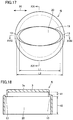
- Fig. 16 illustrates an outer appearance of an ultrasonic sensor 103 according to the present embodiment.
- the ultrasonic sensor 103 includes a case 4j and two external terminals 8 protruding from the case 4j.
- Fig. 17 is a plan view of the case 4j.
- Fig. 18 is a cross-sectional view as viewed in the direction of arrow XVIII-XVIII in Fig. 17 .
- Fig. 19 is a cross-sectional view as viewed in the direction of arrow XIX-XIX in Fig. 17 .
- the case 4j includes the first portion 41 and the second portion 42.
- the maximum length L2 of a part of the internal space 20 inside the second portion 42 along the longitudinal direction 91 is greater than the maximum length L1 of a part of the internal space 20 inside the first portion 41 along the longitudinal direction 91.
- the internal space 20 is elliptical in shape when viewed in the direction perpendicular to the bottom plate 3.
- the part of the internal space 20 inside the first portion 41 and the part of the internal space 20 inside the second portion 42 form the stepped portions 13 at respective ends of the internal space 20 in the longitudinal direction 91.
- the present embodiment can achieve advantageous effects similar to those of the first embodiment.
- Fig. 20 illustrates an outer appearance of an ultrasonic sensor 104 according to the present embodiment.
- the ultrasonic sensor 104 includes a case 4k and two external terminals 8 protruding from the case 4k.
- Fig. 21 is a plan view of the case 4k.
- Fig. 22 is a cross-sectional view as viewed in the direction of arrow XXII-XXII in Fig. 21 .
- Fig. 23 is a cross-sectional view as viewed in the direction of arrow XXIII-XXIII in Fig. 21 .
- the case 4k includes the first portion 41 and the second portion 42.
- the maximum length L2 of a part of the internal space 20 inside the second portion 42 along the longitudinal direction 91 is greater than the maximum length L1 of a part of the internal space 20 inside the first portion 41 along the longitudinal direction 91.
- the internal space 20 is elliptical in shape when viewed in the direction perpendicular to the bottom plate 3.
- the part of the internal space 20 inside the first portion 41 and the part of the internal space 20 inside the second portion 42 form the stepped portions 13 at respective ends of the internal space 20 in the longitudinal direction 91.
- the part of the internal space 20 inside the first portion 41 and the part of the internal space 20 inside the second portion 42 form the stepped portions 14 at respective ends of the internal space 20 in the width direction 92.
- the stepped portions 13 and the stepped portions 14 may be continuous, as illustrated in Fig. 21 .
- the present embodiment can achieve advantageous effects similar to those of the first embodiment.
- the configuration of the first embodiment is particularly preferable. That is, as in the first embodiment, when viewed in the direction perpendicular to the bottom plate 3, it is preferable that the internal space 20 have two sides parallel to the longitudinal direction 91, and that between the two sides, the width of the part of the internal space 20 inside the first portion 41 be equal to the width of the part of the internal space inside the second portion. In the example illustrated in Fig. 6 , the two widths are both W.
- Fig. 24 is a cross-sectional view of an ultrasonic sensor 105 according to the present embodiment.
- the ultrasonic sensor 105 includes the case 4 and one lead wire 16 protruding from the case 4.
- the piezoelectric vibrating element 7 is mounted on the bottom plate 3 of the case 4.
- the internal space 20 of the case 4 is divided into three layers.
- the layer closest to the bottom plate 3 is filled with the filling material 12.
- the filling material 12 may be, for example, silicone.
- a sound-absorbing material 15 is disposed in the layer second closest to the bottom plate 3.
- a substrate 10 is disposed on the surface of the sound-absorbing material 15.
- the layer farthest from the bottom plate 3 is filled with the filling material 12.
- the sound-absorbing material 15 may be, for example, either felt or silicone sponge.
- a part of the lead wire 16 is disposed in the internal space 20 of the case 4, and the other part of the lead wire 16 extends out of the case 4.
- the lead wire 16 is electrically connected at one end thereof to the substrate 10.
- the portion of the lead wire 16 connected to the substrate 10 is covered with the filling material 12.
- the lead wire 16 is provided with a connector 17 at the other end thereof.
- the lead wire 16 includes at least two wires therein.
- a first wire on the surface of the substrate 10 is connected to the case 4 by the lead wire 9a, and a second wire on the surface of the substrate 10 is connected to the piezoelectric vibrating element 7 by the lead wire 9b.
- the lid 11 may not be provided and the upper surface of the filling material 12 may be directly exposed to the outside.
- a lid may be disposed to cover the upper surface of the filling material 12.
- the present embodiment can achieve advantageous effects similar to those of the first embodiment.
- the sound-absorbing material 15 disposed in the internal space 20 as described in the present embodiment for example, back radiation from the piezoelectric vibrating element 7 can be reduced and a dereverberation effect can be achieved.
Landscapes
- Engineering & Computer Science (AREA)
- Radar, Positioning & Navigation (AREA)
- Remote Sensing (AREA)
- Physics & Mathematics (AREA)
- Computer Networks & Wireless Communication (AREA)
- General Physics & Mathematics (AREA)
- Acoustics & Sound (AREA)
- Signal Processing (AREA)
- Transducers For Ultrasonic Waves (AREA)
- Measurement Of Velocity Or Position Using Acoustic Or Ultrasonic Waves (AREA)
Applications Claiming Priority (2)
| Application Number | Priority Date | Filing Date | Title |
|---|---|---|---|
| JP2017181380 | 2017-09-21 | ||
| PCT/JP2018/030840 WO2019058842A1 (fr) | 2017-09-21 | 2018-08-21 | Capteur ultrasonore |
Publications (3)
| Publication Number | Publication Date |
|---|---|
| EP3687191A1 true EP3687191A1 (fr) | 2020-07-29 |
| EP3687191A4 EP3687191A4 (fr) | 2021-06-16 |
| EP3687191B1 EP3687191B1 (fr) | 2024-05-15 |
Family
ID=65811372
Family Applications (1)
| Application Number | Title | Priority Date | Filing Date |
|---|---|---|---|
| EP18858712.5A Active EP3687191B1 (fr) | 2017-09-21 | 2018-08-21 | Capteur ultrasonore |
Country Status (5)
| Country | Link |
|---|---|
| US (1) | US20200200885A1 (fr) |
| EP (1) | EP3687191B1 (fr) |
| JP (1) | JP6863466B2 (fr) |
| CN (1) | CN111133772A (fr) |
| WO (1) | WO2019058842A1 (fr) |
Families Citing this family (8)
| Publication number | Priority date | Publication date | Assignee | Title |
|---|---|---|---|---|
| TWI707146B (zh) * | 2019-06-12 | 2020-10-11 | 千竣科技有限公司 | 超聲波偵測裝置 |
| JP7318495B2 (ja) * | 2019-11-15 | 2023-08-01 | Tdk株式会社 | 超音波デバイス及び流体検出装置 |
| JP7695010B2 (ja) * | 2020-06-17 | 2025-06-18 | パナソニックオートモーティブシステムズ株式会社 | 超音波センサ装置、および、車両 |
| DE112022001312T5 (de) * | 2021-03-02 | 2023-12-21 | Murata Manufacturing Co., Ltd. | Ultraschallsensor |
| USD1024818S1 (en) * | 2021-04-16 | 2024-04-30 | Chengdu Huitong West Electronic Co., Ltd. | Housing of ultrasonic sensor |
| USD1024814S1 (en) * | 2022-07-05 | 2024-04-30 | Chengdu Huitong West Electronic Co., Ltd. | Housing of ultrasonic sensor |
| DE102023102399A1 (de) | 2023-02-01 | 2024-08-01 | Dr. Ing. H.C. F. Porsche Aktiengesellschaft | Anordnung einer Kraftfahrzeugsensorvorrichtung |
| WO2026063430A1 (fr) * | 2024-09-20 | 2026-03-26 | 株式会社村田製作所 | Capteur à ultrasons |
Family Cites Families (19)
| Publication number | Priority date | Publication date | Assignee | Title |
|---|---|---|---|---|
| TW345132U (en) * | 1998-03-26 | 1998-11-11 | shi-xiong Li | Improved structure for sensor of car backing radar |
| US6250162B1 (en) * | 1998-04-24 | 2001-06-26 | Murata Manufacturing Co., Ltd. | Ultrasonic sensor |
| JP3552605B2 (ja) * | 1999-08-31 | 2004-08-11 | 松下電工株式会社 | 超音波振動子 |
| JP4304556B2 (ja) * | 1999-12-03 | 2009-07-29 | 株式会社村田製作所 | 超音波センサ |
| JP2001232294A (ja) * | 2000-02-24 | 2001-08-28 | Matsushita Electric Works Ltd | 超音波振動子 |
| JP3659153B2 (ja) * | 2000-09-26 | 2005-06-15 | 松下電工株式会社 | 超音波振動子 |
| JP2002262383A (ja) * | 2000-12-28 | 2002-09-13 | Matsushita Electric Works Ltd | 超音波振動子 |
| JP2002209294A (ja) | 2001-01-10 | 2002-07-26 | Murata Mfg Co Ltd | 超音波センサ、これを備える電子機器および車両用バックソナー |
| KR100975007B1 (ko) * | 2005-09-09 | 2010-08-09 | 가부시키가이샤 무라타 세이사쿠쇼 | 초음파 센서 |
| CN101072452A (zh) * | 2005-12-27 | 2007-11-14 | 中国科学院声学研究所 | 深海压电水声换能器及其制造方法 |
| JP4742924B2 (ja) * | 2006-03-15 | 2011-08-10 | 株式会社デンソー | 超音波センサ |
| DE102007008744B4 (de) * | 2006-03-15 | 2012-10-31 | Denso Corporation | Ultraschallsensor |
| JP4893322B2 (ja) * | 2006-03-23 | 2012-03-07 | 株式会社デンソー | 超音波センサ |
| JP2007282058A (ja) * | 2006-04-10 | 2007-10-25 | Nippon Ceramic Co Ltd | 超音波センサ |
| DE102006050037A1 (de) * | 2006-10-24 | 2008-04-30 | Robert Bosch Gmbh | Ultraschallwandler |
| CN101740017A (zh) * | 2008-11-12 | 2010-06-16 | 同致电子企业股份有限公司 | 哑铃形腔室的超音波换能器 |
| CN102227919B (zh) * | 2008-12-04 | 2014-04-09 | 株式会社村田制作所 | 超声波接收发送器 |
| KR101553869B1 (ko) * | 2013-07-02 | 2015-09-17 | 현대모비스 주식회사 | 초음파 센서 조립체 |
| JP6493415B2 (ja) * | 2014-12-26 | 2019-04-03 | 株式会社村田製作所 | 超音波センサ |
-
2018
- 2018-08-21 WO PCT/JP2018/030840 patent/WO2019058842A1/fr not_active Ceased
- 2018-08-21 EP EP18858712.5A patent/EP3687191B1/fr active Active
- 2018-08-21 CN CN201880060510.4A patent/CN111133772A/zh not_active Withdrawn
- 2018-08-21 JP JP2019543490A patent/JP6863466B2/ja active Active
-
2020
- 2020-02-28 US US16/804,080 patent/US20200200885A1/en not_active Abandoned
Also Published As
| Publication number | Publication date |
|---|---|
| EP3687191A4 (fr) | 2021-06-16 |
| US20200200885A1 (en) | 2020-06-25 |
| CN111133772A (zh) | 2020-05-08 |
| JP6863466B2 (ja) | 2021-04-21 |
| EP3687191B1 (fr) | 2024-05-15 |
| JPWO2019058842A1 (ja) | 2020-08-27 |
| WO2019058842A1 (fr) | 2019-03-28 |
Similar Documents
| Publication | Publication Date | Title |
|---|---|---|
| EP3687191B1 (fr) | Capteur ultrasonore | |
| US6250162B1 (en) | Ultrasonic sensor | |
| US4754440A (en) | Ultrasonic transducer | |
| JP4438667B2 (ja) | 超音波センサ及び超音波振動子 | |
| CN102726064B (zh) | 超声波振动装置 | |
| US12038541B2 (en) | Ultrasonic sensor | |
| JPWO2007069609A1 (ja) | 超音波トランスデューサ | |
| CA2549704A1 (fr) | Capteur ultrasons et transducteur ultrasons | |
| US20080087090A1 (en) | Ultrasonic sensor for use in automotive vehicle | |
| US8067877B2 (en) | Anti-EMI ultrasonic transducer | |
| US11860272B2 (en) | Ultrasonic touch sensor | |
| JPH10332817A (ja) | 超音波振動子およびその超音波振動子を有する超音波センサ | |
| JP5950742B2 (ja) | 超音波送受波器 | |
| JP3552605B2 (ja) | 超音波振動子 | |
| JP7439728B2 (ja) | 超音波センサ | |
| JP6611992B2 (ja) | 超音波センサ装置及び障害物検知装置 | |
| JP4304556B2 (ja) | 超音波センサ | |
| JP2000032594A (ja) | 超音波送受波器 | |
| CN111295893A (zh) | 超声波传感器 | |
| KR101376347B1 (ko) | 초음파 트랜스듀서 | |
| JP3484358B2 (ja) | 超音波探触子 | |
| JP2001337172A (ja) | 超音波検知器 | |
| JP3628669B2 (ja) | 超音波振動子およびその超音波振動子を有する超音波センサ | |
| JP3651475B2 (ja) | 超音波センサ及びその超音波センサに用いられる超音波振動子 | |
| CN108475501B (zh) | 声换能器组件 |
Legal Events
| Date | Code | Title | Description |
|---|---|---|---|
| STAA | Information on the status of an ep patent application or granted ep patent |
Free format text: STATUS: THE INTERNATIONAL PUBLICATION HAS BEEN MADE |
|
| PUAI | Public reference made under article 153(3) epc to a published international application that has entered the european phase |
Free format text: ORIGINAL CODE: 0009012 |
|
| STAA | Information on the status of an ep patent application or granted ep patent |
Free format text: STATUS: REQUEST FOR EXAMINATION WAS MADE |
|
| 17P | Request for examination filed |
Effective date: 20200303 |
|
| AK | Designated contracting states |
Kind code of ref document: A1 Designated state(s): AL AT BE BG CH CY CZ DE DK EE ES FI FR GB GR HR HU IE IS IT LI LT LU LV MC MK MT NL NO PL PT RO RS SE SI SK SM TR |
|
| AX | Request for extension of the european patent |
Extension state: BA ME |
|
| DAV | Request for validation of the european patent (deleted) | ||
| DAX | Request for extension of the european patent (deleted) | ||
| REG | Reference to a national code |
Ref country code: DE Ref legal event code: R079 Free format text: PREVIOUS MAIN CLASS: H04R0017000000 Ipc: G01S0007521000 Ref country code: DE Ref legal event code: R079 Ref document number: 602018069620 Country of ref document: DE Free format text: PREVIOUS MAIN CLASS: H04R0017000000 Ipc: G01S0007521000 |
|
| A4 | Supplementary search report drawn up and despatched |
Effective date: 20210517 |
|
| RIC1 | Information provided on ipc code assigned before grant |
Ipc: G01S 7/521 20060101AFI20210510BHEP Ipc: G01S 15/931 20200101ALI20210510BHEP Ipc: H04R 17/00 20060101ALI20210510BHEP |
|
| GRAP | Despatch of communication of intention to grant a patent |
Free format text: ORIGINAL CODE: EPIDOSNIGR1 |
|
| STAA | Information on the status of an ep patent application or granted ep patent |
Free format text: STATUS: GRANT OF PATENT IS INTENDED |
|
| INTG | Intention to grant announced |
Effective date: 20231214 |
|
| GRAS | Grant fee paid |
Free format text: ORIGINAL CODE: EPIDOSNIGR3 |
|
| GRAA | (expected) grant |
Free format text: ORIGINAL CODE: 0009210 |
|
| STAA | Information on the status of an ep patent application or granted ep patent |
Free format text: STATUS: THE PATENT HAS BEEN GRANTED |
|
| AK | Designated contracting states |
Kind code of ref document: B1 Designated state(s): AL AT BE BG CH CY CZ DE DK EE ES FI FR GB GR HR HU IE IS IT LI LT LU LV MC MK MT NL NO PL PT RO RS SE SI SK SM TR |
|
| REG | Reference to a national code |
Ref country code: CH Ref legal event code: EP |
|
| REG | Reference to a national code |
Ref country code: IE Ref legal event code: FG4D |
|
| REG | Reference to a national code |
Ref country code: DE Ref legal event code: R096 Ref document number: 602018069620 Country of ref document: DE |
|
| REG | Reference to a national code |
Ref country code: LT Ref legal event code: MG9D |
|
| REG | Reference to a national code |
Ref country code: NL Ref legal event code: MP Effective date: 20240515 |
|
| PG25 | Lapsed in a contracting state [announced via postgrant information from national office to epo] |
Ref country code: IS Free format text: LAPSE BECAUSE OF FAILURE TO SUBMIT A TRANSLATION OF THE DESCRIPTION OR TO PAY THE FEE WITHIN THE PRESCRIBED TIME-LIMIT Effective date: 20240915 |
|
| PG25 | Lapsed in a contracting state [announced via postgrant information from national office to epo] |
Ref country code: BG Free format text: LAPSE BECAUSE OF FAILURE TO SUBMIT A TRANSLATION OF THE DESCRIPTION OR TO PAY THE FEE WITHIN THE PRESCRIBED TIME-LIMIT Effective date: 20240515 |
|
| PG25 | Lapsed in a contracting state [announced via postgrant information from national office to epo] |
Ref country code: HR Free format text: LAPSE BECAUSE OF FAILURE TO SUBMIT A TRANSLATION OF THE DESCRIPTION OR TO PAY THE FEE WITHIN THE PRESCRIBED TIME-LIMIT Effective date: 20240515 Ref country code: FI Free format text: LAPSE BECAUSE OF FAILURE TO SUBMIT A TRANSLATION OF THE DESCRIPTION OR TO PAY THE FEE WITHIN THE PRESCRIBED TIME-LIMIT Effective date: 20240515 |
|
| PG25 | Lapsed in a contracting state [announced via postgrant information from national office to epo] |
Ref country code: GR Free format text: LAPSE BECAUSE OF FAILURE TO SUBMIT A TRANSLATION OF THE DESCRIPTION OR TO PAY THE FEE WITHIN THE PRESCRIBED TIME-LIMIT Effective date: 20240816 |
|
| PG25 | Lapsed in a contracting state [announced via postgrant information from national office to epo] |
Ref country code: PT Free format text: LAPSE BECAUSE OF FAILURE TO SUBMIT A TRANSLATION OF THE DESCRIPTION OR TO PAY THE FEE WITHIN THE PRESCRIBED TIME-LIMIT Effective date: 20240916 |
|
| REG | Reference to a national code |
Ref country code: AT Ref legal event code: MK05 Ref document number: 1687334 Country of ref document: AT Kind code of ref document: T Effective date: 20240515 |
|
| PG25 | Lapsed in a contracting state [announced via postgrant information from national office to epo] |
Ref country code: NL Free format text: LAPSE BECAUSE OF FAILURE TO SUBMIT A TRANSLATION OF THE DESCRIPTION OR TO PAY THE FEE WITHIN THE PRESCRIBED TIME-LIMIT Effective date: 20240515 |
|
| PG25 | Lapsed in a contracting state [announced via postgrant information from national office to epo] |
Ref country code: ES Free format text: LAPSE BECAUSE OF FAILURE TO SUBMIT A TRANSLATION OF THE DESCRIPTION OR TO PAY THE FEE WITHIN THE PRESCRIBED TIME-LIMIT Effective date: 20240515 |
|
| PG25 | Lapsed in a contracting state [announced via postgrant information from national office to epo] |
Ref country code: AT Free format text: LAPSE BECAUSE OF FAILURE TO SUBMIT A TRANSLATION OF THE DESCRIPTION OR TO PAY THE FEE WITHIN THE PRESCRIBED TIME-LIMIT Effective date: 20240515 |
|
| PG25 | Lapsed in a contracting state [announced via postgrant information from national office to epo] |
Ref country code: PL Free format text: LAPSE BECAUSE OF FAILURE TO SUBMIT A TRANSLATION OF THE DESCRIPTION OR TO PAY THE FEE WITHIN THE PRESCRIBED TIME-LIMIT Effective date: 20240515 |
|
| PG25 | Lapsed in a contracting state [announced via postgrant information from national office to epo] |
Ref country code: LV Free format text: LAPSE BECAUSE OF FAILURE TO SUBMIT A TRANSLATION OF THE DESCRIPTION OR TO PAY THE FEE WITHIN THE PRESCRIBED TIME-LIMIT Effective date: 20240515 |
|
| PG25 | Lapsed in a contracting state [announced via postgrant information from national office to epo] |
Ref country code: PT Free format text: LAPSE BECAUSE OF FAILURE TO SUBMIT A TRANSLATION OF THE DESCRIPTION OR TO PAY THE FEE WITHIN THE PRESCRIBED TIME-LIMIT Effective date: 20240916 Ref country code: PL Free format text: LAPSE BECAUSE OF FAILURE TO SUBMIT A TRANSLATION OF THE DESCRIPTION OR TO PAY THE FEE WITHIN THE PRESCRIBED TIME-LIMIT Effective date: 20240515 Ref country code: NO Free format text: LAPSE BECAUSE OF FAILURE TO SUBMIT A TRANSLATION OF THE DESCRIPTION OR TO PAY THE FEE WITHIN THE PRESCRIBED TIME-LIMIT Effective date: 20240815 Ref country code: NL Free format text: LAPSE BECAUSE OF FAILURE TO SUBMIT A TRANSLATION OF THE DESCRIPTION OR TO PAY THE FEE WITHIN THE PRESCRIBED TIME-LIMIT Effective date: 20240515 Ref country code: LV Free format text: LAPSE BECAUSE OF FAILURE TO SUBMIT A TRANSLATION OF THE DESCRIPTION OR TO PAY THE FEE WITHIN THE PRESCRIBED TIME-LIMIT Effective date: 20240515 Ref country code: IS Free format text: LAPSE BECAUSE OF FAILURE TO SUBMIT A TRANSLATION OF THE DESCRIPTION OR TO PAY THE FEE WITHIN THE PRESCRIBED TIME-LIMIT Effective date: 20240915 Ref country code: HR Free format text: LAPSE BECAUSE OF FAILURE TO SUBMIT A TRANSLATION OF THE DESCRIPTION OR TO PAY THE FEE WITHIN THE PRESCRIBED TIME-LIMIT Effective date: 20240515 Ref country code: GR Free format text: LAPSE BECAUSE OF FAILURE TO SUBMIT A TRANSLATION OF THE DESCRIPTION OR TO PAY THE FEE WITHIN THE PRESCRIBED TIME-LIMIT Effective date: 20240816 Ref country code: FI Free format text: LAPSE BECAUSE OF FAILURE TO SUBMIT A TRANSLATION OF THE DESCRIPTION OR TO PAY THE FEE WITHIN THE PRESCRIBED TIME-LIMIT Effective date: 20240515 Ref country code: ES Free format text: LAPSE BECAUSE OF FAILURE TO SUBMIT A TRANSLATION OF THE DESCRIPTION OR TO PAY THE FEE WITHIN THE PRESCRIBED TIME-LIMIT Effective date: 20240515 Ref country code: BG Free format text: LAPSE BECAUSE OF FAILURE TO SUBMIT A TRANSLATION OF THE DESCRIPTION OR TO PAY THE FEE WITHIN THE PRESCRIBED TIME-LIMIT Effective date: 20240515 Ref country code: AT Free format text: LAPSE BECAUSE OF FAILURE TO SUBMIT A TRANSLATION OF THE DESCRIPTION OR TO PAY THE FEE WITHIN THE PRESCRIBED TIME-LIMIT Effective date: 20240515 Ref country code: RS Free format text: LAPSE BECAUSE OF FAILURE TO SUBMIT A TRANSLATION OF THE DESCRIPTION OR TO PAY THE FEE WITHIN THE PRESCRIBED TIME-LIMIT Effective date: 20240815 |
|
| PG25 | Lapsed in a contracting state [announced via postgrant information from national office to epo] |
Ref country code: DK Free format text: LAPSE BECAUSE OF FAILURE TO SUBMIT A TRANSLATION OF THE DESCRIPTION OR TO PAY THE FEE WITHIN THE PRESCRIBED TIME-LIMIT Effective date: 20240515 |
|
| PG25 | Lapsed in a contracting state [announced via postgrant information from national office to epo] |
Ref country code: EE Free format text: LAPSE BECAUSE OF FAILURE TO SUBMIT A TRANSLATION OF THE DESCRIPTION OR TO PAY THE FEE WITHIN THE PRESCRIBED TIME-LIMIT Effective date: 20240515 |
|
| PG25 | Lapsed in a contracting state [announced via postgrant information from national office to epo] |
Ref country code: CZ Free format text: LAPSE BECAUSE OF FAILURE TO SUBMIT A TRANSLATION OF THE DESCRIPTION OR TO PAY THE FEE WITHIN THE PRESCRIBED TIME-LIMIT Effective date: 20240515 |
|
| PG25 | Lapsed in a contracting state [announced via postgrant information from national office to epo] |
Ref country code: SK Free format text: LAPSE BECAUSE OF FAILURE TO SUBMIT A TRANSLATION OF THE DESCRIPTION OR TO PAY THE FEE WITHIN THE PRESCRIBED TIME-LIMIT Effective date: 20240515 Ref country code: RO Free format text: LAPSE BECAUSE OF FAILURE TO SUBMIT A TRANSLATION OF THE DESCRIPTION OR TO PAY THE FEE WITHIN THE PRESCRIBED TIME-LIMIT Effective date: 20240515 |
|
| PG25 | Lapsed in a contracting state [announced via postgrant information from national office to epo] |
Ref country code: SM Free format text: LAPSE BECAUSE OF FAILURE TO SUBMIT A TRANSLATION OF THE DESCRIPTION OR TO PAY THE FEE WITHIN THE PRESCRIBED TIME-LIMIT Effective date: 20240515 |
|
| PG25 | Lapsed in a contracting state [announced via postgrant information from national office to epo] |
Ref country code: SM Free format text: LAPSE BECAUSE OF FAILURE TO SUBMIT A TRANSLATION OF THE DESCRIPTION OR TO PAY THE FEE WITHIN THE PRESCRIBED TIME-LIMIT Effective date: 20240515 Ref country code: SK Free format text: LAPSE BECAUSE OF FAILURE TO SUBMIT A TRANSLATION OF THE DESCRIPTION OR TO PAY THE FEE WITHIN THE PRESCRIBED TIME-LIMIT Effective date: 20240515 Ref country code: RO Free format text: LAPSE BECAUSE OF FAILURE TO SUBMIT A TRANSLATION OF THE DESCRIPTION OR TO PAY THE FEE WITHIN THE PRESCRIBED TIME-LIMIT Effective date: 20240515 Ref country code: EE Free format text: LAPSE BECAUSE OF FAILURE TO SUBMIT A TRANSLATION OF THE DESCRIPTION OR TO PAY THE FEE WITHIN THE PRESCRIBED TIME-LIMIT Effective date: 20240515 Ref country code: DK Free format text: LAPSE BECAUSE OF FAILURE TO SUBMIT A TRANSLATION OF THE DESCRIPTION OR TO PAY THE FEE WITHIN THE PRESCRIBED TIME-LIMIT Effective date: 20240515 Ref country code: CZ Free format text: LAPSE BECAUSE OF FAILURE TO SUBMIT A TRANSLATION OF THE DESCRIPTION OR TO PAY THE FEE WITHIN THE PRESCRIBED TIME-LIMIT Effective date: 20240515 |
|
| PG25 | Lapsed in a contracting state [announced via postgrant information from national office to epo] |
Ref country code: IT Free format text: LAPSE BECAUSE OF FAILURE TO SUBMIT A TRANSLATION OF THE DESCRIPTION OR TO PAY THE FEE WITHIN THE PRESCRIBED TIME-LIMIT Effective date: 20240515 |
|
| REG | Reference to a national code |
Ref country code: DE Ref legal event code: R097 Ref document number: 602018069620 Country of ref document: DE |
|
| PLBE | No opposition filed within time limit |
Free format text: ORIGINAL CODE: 0009261 |
|
| STAA | Information on the status of an ep patent application or granted ep patent |
Free format text: STATUS: NO OPPOSITION FILED WITHIN TIME LIMIT |
|
| REG | Reference to a national code |
Ref country code: CH Ref legal event code: PL |
|
| PG25 | Lapsed in a contracting state [announced via postgrant information from national office to epo] |
Ref country code: LU Free format text: LAPSE BECAUSE OF NON-PAYMENT OF DUE FEES Effective date: 20240821 |
|
| 26N | No opposition filed |
Effective date: 20250218 |
|
| GBPC | Gb: european patent ceased through non-payment of renewal fee |
Effective date: 20240821 |
|
| PG25 | Lapsed in a contracting state [announced via postgrant information from national office to epo] |
Ref country code: SI Free format text: LAPSE BECAUSE OF FAILURE TO SUBMIT A TRANSLATION OF THE DESCRIPTION OR TO PAY THE FEE WITHIN THE PRESCRIBED TIME-LIMIT Effective date: 20240515 Ref country code: MC Free format text: LAPSE BECAUSE OF FAILURE TO SUBMIT A TRANSLATION OF THE DESCRIPTION OR TO PAY THE FEE WITHIN THE PRESCRIBED TIME-LIMIT Effective date: 20240515 Ref country code: CH Free format text: LAPSE BECAUSE OF NON-PAYMENT OF DUE FEES Effective date: 20240831 |
|
| REG | Reference to a national code |
Ref country code: BE Ref legal event code: MM Effective date: 20240831 |
|
| PG25 | Lapsed in a contracting state [announced via postgrant information from national office to epo] |
Ref country code: GB Free format text: LAPSE BECAUSE OF NON-PAYMENT OF DUE FEES Effective date: 20240821 |
|
| PG25 | Lapsed in a contracting state [announced via postgrant information from national office to epo] |
Ref country code: BE Free format text: LAPSE BECAUSE OF NON-PAYMENT OF DUE FEES Effective date: 20240831 |
|
| PG25 | Lapsed in a contracting state [announced via postgrant information from national office to epo] |
Ref country code: IE Free format text: LAPSE BECAUSE OF NON-PAYMENT OF DUE FEES Effective date: 20240821 |
|
| PG25 | Lapsed in a contracting state [announced via postgrant information from national office to epo] |
Ref country code: SE Free format text: LAPSE BECAUSE OF FAILURE TO SUBMIT A TRANSLATION OF THE DESCRIPTION OR TO PAY THE FEE WITHIN THE PRESCRIBED TIME-LIMIT Effective date: 20240515 |
|
| PGFP | Annual fee paid to national office [announced via postgrant information from national office to epo] |
Ref country code: DE Payment date: 20250820 Year of fee payment: 8 |
|
| PGFP | Annual fee paid to national office [announced via postgrant information from national office to epo] |
Ref country code: FR Payment date: 20250828 Year of fee payment: 8 |
|
| PG25 | Lapsed in a contracting state [announced via postgrant information from national office to epo] |
Ref country code: CY Free format text: LAPSE BECAUSE OF FAILURE TO SUBMIT A TRANSLATION OF THE DESCRIPTION OR TO PAY THE FEE WITHIN THE PRESCRIBED TIME-LIMIT; INVALID AB INITIO Effective date: 20180821 |
|
| PG25 | Lapsed in a contracting state [announced via postgrant information from national office to epo] |
Ref country code: HU Free format text: LAPSE BECAUSE OF FAILURE TO SUBMIT A TRANSLATION OF THE DESCRIPTION OR TO PAY THE FEE WITHIN THE PRESCRIBED TIME-LIMIT; INVALID AB INITIO Effective date: 20180821 |
|
| PG25 | Lapsed in a contracting state [announced via postgrant information from national office to epo] |
Ref country code: TR Free format text: LAPSE BECAUSE OF FAILURE TO SUBMIT A TRANSLATION OF THE DESCRIPTION OR TO PAY THE FEE WITHIN THE PRESCRIBED TIME-LIMIT Effective date: 20240515 |
|
| PG25 | Lapsed in a contracting state [announced via postgrant information from national office to epo] |
Ref country code: LT Free format text: LAPSE BECAUSE OF FAILURE TO SUBMIT A TRANSLATION OF THE DESCRIPTION OR TO PAY THE FEE WITHIN THE PRESCRIBED TIME-LIMIT Effective date: 20240515 |