EP3687262A1 - Dispositif générateur de rayonnement électromagnétique de l'ordre du nanomètre - Google Patents
Dispositif générateur de rayonnement électromagnétique de l'ordre du nanomètre Download PDFInfo
- Publication number
- EP3687262A1 EP3687262A1 EP19000040.6A EP19000040A EP3687262A1 EP 3687262 A1 EP3687262 A1 EP 3687262A1 EP 19000040 A EP19000040 A EP 19000040A EP 3687262 A1 EP3687262 A1 EP 3687262A1
- Authority
- EP
- European Patent Office
- Prior art keywords
- exciting
- inductors
- inductor
- excited
- winding
- Prior art date
- Legal status (The legal status is an assumption and is not a legal conclusion. Google has not performed a legal analysis and makes no representation as to the accuracy of the status listed.)
- Withdrawn
Links
- 230000005670 electromagnetic radiation Effects 0.000 title claims abstract description 36
- 238000004804 winding Methods 0.000 claims abstract description 74
- 230000004907 flux Effects 0.000 claims abstract description 21
- 230000005291 magnetic effect Effects 0.000 claims abstract description 19
- 239000002772 conduction electron Substances 0.000 claims abstract description 11
- 230000006698 induction Effects 0.000 claims abstract description 9
- 239000000463 material Substances 0.000 claims description 23
- RYGMFSIKBFXOCR-UHFFFAOYSA-N Copper Chemical compound [Cu] RYGMFSIKBFXOCR-UHFFFAOYSA-N 0.000 claims description 9
- 239000007789 gas Substances 0.000 claims description 9
- 230000010287 polarization Effects 0.000 claims description 8
- 239000007788 liquid Substances 0.000 claims description 7
- BQCADISMDOOEFD-UHFFFAOYSA-N Silver Chemical compound [Ag] BQCADISMDOOEFD-UHFFFAOYSA-N 0.000 claims description 6
- 239000002245 particle Substances 0.000 claims description 5
- 239000007787 solid Substances 0.000 claims description 5
- 239000003989 dielectric material Substances 0.000 claims description 4
- 230000005672 electromagnetic field Effects 0.000 claims description 4
- 229910052709 silver Inorganic materials 0.000 claims description 4
- 239000004332 silver Substances 0.000 claims description 4
- 239000002612 dispersion medium Substances 0.000 claims description 3
- 239000012153 distilled water Substances 0.000 claims description 3
- 230000003993 interaction Effects 0.000 claims description 3
- 230000010363 phase shift Effects 0.000 claims description 3
- XLYOFNOQVPJJNP-UHFFFAOYSA-N water Chemical compound O XLYOFNOQVPJJNP-UHFFFAOYSA-N 0.000 claims description 3
- 230000005284 excitation Effects 0.000 claims 1
- 230000005855 radiation Effects 0.000 abstract description 8
- 239000003814 drug Substances 0.000 abstract description 2
- 230000000694 effects Effects 0.000 abstract description 2
- 230000007704 transition Effects 0.000 abstract description 2
- 238000010586 diagram Methods 0.000 description 11
- 230000006378 damage Effects 0.000 description 10
- 239000002184 metal Substances 0.000 description 10
- 229910052751 metal Inorganic materials 0.000 description 10
- 239000003574 free electron Substances 0.000 description 9
- 239000010949 copper Substances 0.000 description 8
- 229910052802 copper Inorganic materials 0.000 description 7
- 239000004215 Carbon black (E152) Substances 0.000 description 5
- 230000008859 change Effects 0.000 description 5
- 229930195733 hydrocarbon Natural products 0.000 description 5
- 150000002739 metals Chemical class 0.000 description 5
- 238000000034 method Methods 0.000 description 5
- 230000005274 electronic transitions Effects 0.000 description 4
- 150000002430 hydrocarbons Chemical class 0.000 description 4
- 230000008569 process Effects 0.000 description 4
- 239000000126 substance Substances 0.000 description 4
- 230000005865 ionizing radiation Effects 0.000 description 3
- 229920000126 latex Polymers 0.000 description 3
- 239000004816 latex Substances 0.000 description 3
- 230000002226 simultaneous effect Effects 0.000 description 3
- 239000004020 conductor Substances 0.000 description 2
- 239000013078 crystal Substances 0.000 description 2
- 230000001419 dependent effect Effects 0.000 description 2
- 238000005516 engineering process Methods 0.000 description 2
- 239000004065 semiconductor Substances 0.000 description 2
- 229910000859 α-Fe Inorganic materials 0.000 description 2
- 241000931526 Acer campestre Species 0.000 description 1
- 230000005461 Bremsstrahlung Effects 0.000 description 1
- 230000001133 acceleration Effects 0.000 description 1
- 239000003990 capacitor Substances 0.000 description 1
- 230000000739 chaotic effect Effects 0.000 description 1
- 239000003795 chemical substances by application Substances 0.000 description 1
- 238000010276 construction Methods 0.000 description 1
- 239000000975 dye Substances 0.000 description 1
- 230000005684 electric field Effects 0.000 description 1
- 230000005611 electricity Effects 0.000 description 1
- 238000005265 energy consumption Methods 0.000 description 1
- 238000002474 experimental method Methods 0.000 description 1
- 239000003302 ferromagnetic material Substances 0.000 description 1
- 239000012634 fragment Substances 0.000 description 1
- 239000000295 fuel oil Substances 0.000 description 1
- 239000011521 glass Substances 0.000 description 1
- 238000010438 heat treatment Methods 0.000 description 1
- 239000008131 herbal destillate Substances 0.000 description 1
- 239000002609 medium Substances 0.000 description 1
- 229920006173 natural rubber latex Polymers 0.000 description 1
- 230000010355 oscillation Effects 0.000 description 1
- 239000003209 petroleum derivative Substances 0.000 description 1
- 238000002360 preparation method Methods 0.000 description 1
- 238000000746 purification Methods 0.000 description 1
- 230000009467 reduction Effects 0.000 description 1
- 230000001105 regulatory effect Effects 0.000 description 1
- 230000001954 sterilising effect Effects 0.000 description 1
- 238000004659 sterilization and disinfection Methods 0.000 description 1
Images


Classifications
-
- H—ELECTRICITY
- H05—ELECTRIC TECHNIQUES NOT OTHERWISE PROVIDED FOR
- H05G—X-RAY TECHNIQUE
- H05G2/00—Apparatus or processes specially adapted for producing X-rays, not involving X-ray tubes, e.g. involving generation of a plasma
-
- H—ELECTRICITY
- H01—ELECTRIC ELEMENTS
- H01Q—ANTENNAS, i.e. RADIO AERIALS
- H01Q1/00—Details of, or arrangements associated with, antennas
- H01Q1/50—Structural association of antennas with earthing switches, lead-in devices or lightning protectors
-
- H—ELECTRICITY
- H01—ELECTRIC ELEMENTS
- H01S—DEVICES USING THE PROCESS OF LIGHT AMPLIFICATION BY STIMULATED EMISSION OF RADIATION [LASER] TO AMPLIFY OR GENERATE LIGHT; DEVICES USING STIMULATED EMISSION OF ELECTROMAGNETIC RADIATION IN WAVE RANGES OTHER THAN OPTICAL
- H01S1/00—Masers, i.e. devices using stimulated emission of electromagnetic radiation in the microwave range
- H01S1/005—Masers, i.e. devices using stimulated emission of electromagnetic radiation in the microwave range using a relativistic beam of charged particles, e.g. electron cyclotron maser, gyrotron
-
- H—ELECTRICITY
- H01—ELECTRIC ELEMENTS
- H01F—MAGNETS; INDUCTANCES; TRANSFORMERS; SELECTION OF MATERIALS FOR THEIR MAGNETIC PROPERTIES
- H01F17/00—Fixed inductances of the signal type
- H01F17/04—Fixed inductances of the signal type with magnetic core
- H01F17/045—Fixed inductances of the signal type with magnetic core with core of cylindric geometry and coil wound along its longitudinal axis, i.e. rod or drum core
-
- H—ELECTRICITY
- H01—ELECTRIC ELEMENTS
- H01F—MAGNETS; INDUCTANCES; TRANSFORMERS; SELECTION OF MATERIALS FOR THEIR MAGNETIC PROPERTIES
- H01F17/00—Fixed inductances of the signal type
- H01F17/04—Fixed inductances of the signal type with magnetic core
- H01F17/06—Fixed inductances of the signal type with magnetic core with core substantially closed in itself, e.g. toroid
- H01F17/062—Toroidal core with turns of coil around it
-
- H—ELECTRICITY
- H01—ELECTRIC ELEMENTS
- H01F—MAGNETS; INDUCTANCES; TRANSFORMERS; SELECTION OF MATERIALS FOR THEIR MAGNETIC PROPERTIES
- H01F27/00—Details of transformers or inductances, in general
- H01F27/42—Circuits specially adapted for the purpose of modifying, or compensating for, electric characteristics of transformers, reactors, or choke coils
-
- H—ELECTRICITY
- H01—ELECTRIC ELEMENTS
- H01Q—ANTENNAS, i.e. RADIO AERIALS
- H01Q1/00—Details of, or arrangements associated with, antennas
- H01Q1/36—Structural form of radiating elements, e.g. cone, spiral, umbrella; Particular materials used therewith
-
- H—ELECTRICITY
- H01—ELECTRIC ELEMENTS
- H01Q—ANTENNAS, i.e. RADIO AERIALS
- H01Q1/00—Details of, or arrangements associated with, antennas
- H01Q1/36—Structural form of radiating elements, e.g. cone, spiral, umbrella; Particular materials used therewith
- H01Q1/364—Structural form of radiating elements, e.g. cone, spiral, umbrella; Particular materials used therewith using a particular conducting material, e.g. superconductor
-
- H—ELECTRICITY
- H01—ELECTRIC ELEMENTS
- H01Q—ANTENNAS, i.e. RADIO AERIALS
- H01Q23/00—Antennas with active circuits or circuit elements integrated within them or attached to them
-
- H—ELECTRICITY
- H01—ELECTRIC ELEMENTS
- H01S—DEVICES USING THE PROCESS OF LIGHT AMPLIFICATION BY STIMULATED EMISSION OF RADIATION [LASER] TO AMPLIFY OR GENERATE LIGHT; DEVICES USING STIMULATED EMISSION OF ELECTROMAGNETIC RADIATION IN WAVE RANGES OTHER THAN OPTICAL
- H01S3/00—Lasers, i.e. devices using stimulated emission of electromagnetic radiation in the infrared, visible or ultraviolet wave range
- H01S3/09—Processes or apparatus for excitation, e.g. pumping
- H01S3/0903—Free-electron laser
-
- H—ELECTRICITY
- H01—ELECTRIC ELEMENTS
- H01F—MAGNETS; INDUCTANCES; TRANSFORMERS; SELECTION OF MATERIALS FOR THEIR MAGNETIC PROPERTIES
- H01F27/00—Details of transformers or inductances, in general
- H01F27/28—Coils; Windings; Conductive connections
- H01F27/2871—Pancake coils
Definitions
- the present invention relates to the field of quantum radio physics and is a solid-state nanometre range electromagnetic radiation quantum generator. It may be widely used in technics, nanotechnology, physics, chemistry, biology and medicine. More specifically, the present invention is applicable to sterilization and gas purification systems, fluorescent lighting devices and so on.
- Quantum generators There are several known types of quantum generators that vary in type of working agent used: solid-state (crystal or glass), gas, semiconductor or dye-based ones. Quantum generators may also vary by the active medium forming particles, which could be molecules, atoms, free or conduction electrons.
- the disadvantages of the known devices are: complexity of the technical implementation, limited power of electromagnetic radiation, requirement for low operating temperatures, strong magnetic and electric fields.
- the stated disadvantages of the known devices show that there is a task consisting in the creation of such a solution that would ensure the efficient generation of electromagnetic radiation of the nanometre range with low power consumption and with a simple technical design.
- the technical problem of obtaining such radiation is caused by the need to create conditions under which the motion of free electrons in a metal acquires a variable spiral character, the kinetic energy of the electrons' motion becomes quantized, and the electronic transitions from higher energy levels to lower ones result the emission of an electromagnetic wave.
- the technical result that solves these problems with a significant reduction in energy costs is the effect of generation radiation by conductivity electrons of in the nanometre range electromagnetic waves, which can be objectively manifested when using the proposed device.
- the phenomenon of radiation of electromagnetic waves during the movement of conduction electrons along spiral paths is used for generation of electromagnetic radiation.
- three inductors are used, the first and second ones as exciting, and the third one as excited.
- the alternating electric currents of the exciting inductors create uniformly variable counter-fluxes of mutual induction.
- the change of these fluxes induces uniformly variable electromotive forces in the winding of the excited inductor located between two exciting ones.
- the phase angle of the currents of the exciting inductors is set in such a way as to ensure the creation of uniformly variable magnetic counter-fluxes.
- magnetic counter-fluxes provide simultaneous effect of two equal but opposite Lorentz forces on the conduction electrons.
- Lorentz forces and opposite uniformly variable electromotive forces the motion of free electrons in the winding of the excited inductor acquires a variable spiral character, its kinetic energy becomes quantized, and the electronic transitions from higher to lower energy levels are accompanied by the emission of an electromagnetic wave.
- a device was created for generation of nanometre range electromagnetic radiation, which makes it possible to achieve the above technical result. It includes at least two devices for adjusting electrical power, at least one phase shifting device, at least one electromagnetic wave emitter, at least two exciting and one excited inductors.
- the excited inductor is connected to the emitter of electromagnetic waves, while both exciting inductors with the same electrical parameters are connected to the AC network through electric power adjustment devices, enabling electric signals with equal amplitudes.
- the first exciting inductor is connected to the adjusting device through a phase shifting device, which makes it possible to adjust the phase angle between the signals on the first and second exciting inductors and therefore provide creation of the uniformly variable counter-fluxes of mutual induction by the alternating currents of the exciting inductors.
- the interaction of these uniformly variable magnetic fluxes with the excited inductor makes the movement of conduction electrons in its winding spiral and alternate, providing generation of electromagnetic radiation in the nanometre range.
- the claimed device allows to create conditions under which the movement of free electrons in a metal acquires a variable spiral character, the kinetic energy of the electrons' movement quantizes and electronic transitions from higher energy levels to lower levels are accompanied by the emission of an electromagnetic wave.
- the generator of electrical signals of adjustable frequency and amplitude should be connected to the power supply source; the first exciting inductor should be connected to the electrical signal generator through the phase shifting device and the first power adjustment device, and the second exciting inductor - through the second power adjustment device.
- Both AC network and AC or DC source could be used.
- a particular case is the connection to the AC network with a voltage of 220 V and a frequency of 50 Hz.
- the first exciting inductor should be located coaxially with the second one, and the excited inductor should be located between the first and second exciting inductors and coaxially with them.
- the first and second exciting inductors should have the same inductance, capacitance and other electrical parameters.
- the number of winding turns in the first exciting inductor should be equal to the number of winding turns of the second one. However, the number of winding turns in the first exciting inductor may differ from the number of turns in the second one - it may be more or less than the number of winding turns in the second exciting inductance coil.
- the phase shift device should provide the phase angle between the signals on the first and second exciting inductors in the range from 0° to 360°. A particular case is the phase angle of 90 degrees.
- the claimed device allows to obtain electromagnetic radiation with its wavelength and frequency being dependent on the Fermi velocity of metals used as the material of inductors' windings.
- metals such as copper, silver, etc. may be used. Fermi velocities of some metals are listed in a table below.
- Electromagnetic radiation of nanometre range generating device comprises the generator of electrical signals of adjustable frequency and amplitude (1), at least two electric power adjustment devices (2) and (3), at least one phase shifting device (4), at least two exciting inductors (5) and (6), the excited inductor (7) and at least one electromagnetic wave emitter (8) ( Fig. 1 ).
- the generator of electrical signals of adjustable frequency and amplitude (1) is connected to the power supply source; the first exciting inductor (5) is connected to the electrical signal generator (1) through the phase shifting device (4) and the first power adjustment device (2), and the second exciting inductor (6) - through the second power adjustment device (3).
- the first exciting inductor (5) is made coaxial with the second one (6), and the excited inductor (7) is located inside the space between the first (5) and second (6) exciting inductors and coaxially with them.
- the number of turns in the windings of first (5) and second (6) exciting inductors can be equal or different.
- the first (5) and second (6) exciting inductors have the same inductance, capacitance and other electrical parameters.
- the emitter of electromagnetic waves (8) is connected to the terminals of the excited inductor winding (7) ( Fig. 1 ).
- Both AC network ( Fig. 2 , 10 ) and AC or DC source ( Fig. 1 , 3 - 9 ) could be used.
- a particular case is the connection to the AC network with a voltage of 220 V and a frequency of 50 Hz.
- the amplitudes of the currents of the exciting inductors (5) and (6) are adjusted and set equal in absolute value.
- phase angle between the signals on the first (5) and second (6) exciting inductors is adjusted in the range from 0° to 360°.
- a particular case is the phase angle of 90 degrees.
- the principle of operation of the claimed device is based on the following.
- the first exciting inductor (5) is supplied with alternating electric current from the adjustable frequency and amplitude generator (1) through the first electric power adjustment device (2) and the phase shifting device (4).
- the alternating current of the first exciting inductor (5) creates the first flux of mutual induction and the change of this flux induces the first electromotive force in the excited coil (7).
- the second exciting inductor (6) is supplied with alternating electric current from the adjustable frequency and amplitude generator (1) through the second electric power adjustment device (3).
- the alternating current of the second exciting inductor (6) in turn creates a second mutual induction flux, the change of which induces a second, counter-first electromotive force in the excited inductor (7).
- the electric current that is supplied to the first exciting inductor (5) differs in phase from the electric current that is supplied to the second exciting inductor (6).
- the amplitudes of the alternating currents in the exciting inductors (5) and (6) are regulated by electric power adjustment devices and are set equal in absolute value.
- the phase shifting device (4) provides the phase shift of the signal fed to the first exciting inductor (5), relative to the phase of the signal that goes to the second exciting inductor (6), by an angle that is necessary and sufficient to create uniformly variable magnetic fluxes, which provide a simultaneous effect of two equal but opposite Lorentz forces on the conduction electrons.
- the metal wire of the winding of all inductors (5), (6) and (7) can be made of copper, silver and other metals.
- the electromagnetic wave propagates into space through the electromagnetic waves emitter (8), which is connected to the terminal of the excited inductor winding (7).
- the electromagnetic radiation of nanometre range generating device comprises a first electric power adjustment device (2), a phase shifting device (4), a second electric power adjustment device (3), two exciting inductors (5) and (6), one excited inductor (7) and two emitters of electromagnetic waves (8) and (9) ( Fig. 10 ).
- the first exciting inductor (5) is connected to AC network with a voltage of 220 V and a frequency of 50 Hz through the first electric power adjustment device (2) and phase shifting device (4), the second exciting inductor (6) is connected to the same AC network through a second electric power adjustment device (3).
- the windings of the first (5) and second (6) exciting inductors are wound around E-shaped core made of ferrite material and have an equal number of turns.
- the winding of the excited inductor (7) is made on the same E-shaped core made of ferromagnetic material and placed between the first (5) and second (6) exciting inductors.
- the number of turns of the excited inductor winding significantly exceeds the number of turns of the exciting inductors windings.
- W1 is the winding of the first exciting inductor (5).
- W2 is the winding of the second exciting inductor (6).
- W3 is the winding of the excited inductor (7).
- the metal of the winding wire is copper.
- the phase shifting device (4) is made in the form of a bridge of resistors and capacitors ( Fig. 11 ), the ratio of the ratings of which allows to set the required shift angle ⁇ between the phases of the signals fed to the first (5) and second (6) exciting inductors.
- Electromagnetic wave emitters (8) and (9) connected to the terminals of the excited inductor winding (7) are made from the pin parts of 14-pin angular connectors, 2,54 mm, type AMP-Latch.
- polymeric high-molecular hydrocarbon compound - a natural rubber latex was chosen.
- a latex article was placed in the space between the emitters (8) and (9) ( Fig. 14 ).
- amplitudes of the currents in the first (5) and second (6) exciting inductors were set to be equal in absolute value by electric power control devices (2) and (3). Equal in amplitude, but shifted in phase, the alternating electric currents of the exciting inductors (5) and (6) began to create uniformly variable counter-fluxes of mutual induction. The change in these fluxes led to the induction in the winding of the excited inductor of opposite electromotive forces. In this case, the opposite magnetic fluxes provided a simultaneous effect on the conduction electrons of two opposite uniformly variable Lorentz forces.
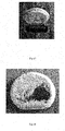
- Fig. 15 depicts the start of the process
- Fig. 16 the state of the material after 1 min
- Fig. 17 the state of the material after 2 min.
- the destruction of the polymeric hydrocarbon material occurred without a change in temperature (heating) of both the emitters and the material being destroyed. In the process of destruction, no mechanical, thermal, chemical, electrical and other methods of influence on the substance were used.
- the destruction of hydrocarbon bonds ( Fig. 18 ) under the influence of ionizing electromagnetic radiation occurred within 2 minutes with an electrical power consumption of 4,7 W.
- Electromagnetic radiation with the above parameters refers to ionizing radiation and can be used in all applications of ionizing radiation, including the technology of substances destruction in solid, liquid and gaseous state.
Landscapes
- Engineering & Computer Science (AREA)
- Power Engineering (AREA)
- Physics & Mathematics (AREA)
- Electromagnetism (AREA)
- Optics & Photonics (AREA)
- Plasma & Fusion (AREA)
- Microelectronics & Electronic Packaging (AREA)
- Physical Or Chemical Processes And Apparatus (AREA)
- Water Treatment By Electricity Or Magnetism (AREA)
Priority Applications (5)
| Application Number | Priority Date | Filing Date | Title |
|---|---|---|---|
| EP19000040.6A EP3687262A1 (fr) | 2019-01-24 | 2019-01-24 | Dispositif générateur de rayonnement électromagnétique de l'ordre du nanomètre |
| SG10201911759PA SG10201911759PA (en) | 2019-01-24 | 2019-12-06 | Electromagnetic radiation of nanometer range generating device |
| US16/706,831 US20210057863A1 (en) | 2019-01-24 | 2019-12-09 | Electromagnetic radiation of nanometer range generating device |
| CN202010043119.2A CN111478043A (zh) | 2019-01-24 | 2020-01-15 | 纳米范围的电磁辐射生成设备 |
| PCT/EE2020/000001 WO2020151796A1 (fr) | 2019-01-24 | 2020-01-16 | Rayonnement électromagnétique d'un dispositif de génération de gamme nanométrique |
Applications Claiming Priority (1)
| Application Number | Priority Date | Filing Date | Title |
|---|---|---|---|
| EP19000040.6A EP3687262A1 (fr) | 2019-01-24 | 2019-01-24 | Dispositif générateur de rayonnement électromagnétique de l'ordre du nanomètre |
Publications (1)
| Publication Number | Publication Date |
|---|---|
| EP3687262A1 true EP3687262A1 (fr) | 2020-07-29 |
Family
ID=65234384
Family Applications (1)
| Application Number | Title | Priority Date | Filing Date |
|---|---|---|---|
| EP19000040.6A Withdrawn EP3687262A1 (fr) | 2019-01-24 | 2019-01-24 | Dispositif générateur de rayonnement électromagnétique de l'ordre du nanomètre |
Country Status (5)
| Country | Link |
|---|---|
| US (1) | US20210057863A1 (fr) |
| EP (1) | EP3687262A1 (fr) |
| CN (1) | CN111478043A (fr) |
| SG (1) | SG10201911759PA (fr) |
| WO (1) | WO2020151796A1 (fr) |
Citations (4)
| Publication number | Priority date | Publication date | Assignee | Title |
|---|---|---|---|---|
| US4376917A (en) | 1980-06-25 | 1983-03-15 | The United States Of America As Represented By The Secretary Of The Navy | Solid-state cyclotron maser |
| RU2488243C2 (ru) | 2010-08-26 | 2013-07-20 | Государственное образовательное учреждение высшего профессионального образования "Российский университет дружбы народов" (РУДН) | Плазменный генератор тормозного излучения |
| WO2013191576A1 (fr) * | 2012-06-22 | 2013-12-27 | Samsonov Vitaly Fedorovich | Procédé de transmission d'énergie électromagnétique et dispositif de mise en oeuvre |
| US20140098929A1 (en) * | 2006-12-20 | 2014-04-10 | Analogic Corporation | Non-contact rotary power transfer system |
Family Cites Families (6)
| Publication number | Priority date | Publication date | Assignee | Title |
|---|---|---|---|---|
| US6791298B2 (en) * | 2001-11-05 | 2004-09-14 | Shakti Systems, Inc. | Monolithic battery charging device |
| US7262543B2 (en) * | 2004-09-08 | 2007-08-28 | United States Of America As Represented By The Administrator Of The National Aeronautics And Space Administration | System and method for monitoring piezoelectric material performance |
| RU2351045C1 (ru) * | 2007-07-10 | 2009-03-27 | Институт физики металлов УрО РАН | Твердотельный мазер на электронах проводимости |
| US8058856B2 (en) * | 2007-08-24 | 2011-11-15 | Upi Semiconductor Corporation | Multi-phase DC-DC converter and method for balancing channel currents |
| DE102014119061A1 (de) * | 2014-12-18 | 2016-06-23 | Endress + Hauser Gmbh + Co. Kg | Vibronischer Sensor |
| SG10201701603PA (en) * | 2016-03-03 | 2017-10-30 | Lifeng Tech Ltd | System and method for imparting electromagnetic energy into water and use thereof |
-
2019
- 2019-01-24 EP EP19000040.6A patent/EP3687262A1/fr not_active Withdrawn
- 2019-12-06 SG SG10201911759PA patent/SG10201911759PA/en unknown
- 2019-12-09 US US16/706,831 patent/US20210057863A1/en not_active Abandoned
-
2020
- 2020-01-15 CN CN202010043119.2A patent/CN111478043A/zh active Pending
- 2020-01-16 WO PCT/EE2020/000001 patent/WO2020151796A1/fr not_active Ceased
Patent Citations (4)
| Publication number | Priority date | Publication date | Assignee | Title |
|---|---|---|---|---|
| US4376917A (en) | 1980-06-25 | 1983-03-15 | The United States Of America As Represented By The Secretary Of The Navy | Solid-state cyclotron maser |
| US20140098929A1 (en) * | 2006-12-20 | 2014-04-10 | Analogic Corporation | Non-contact rotary power transfer system |
| RU2488243C2 (ru) | 2010-08-26 | 2013-07-20 | Государственное образовательное учреждение высшего профессионального образования "Российский университет дружбы народов" (РУДН) | Плазменный генератор тормозного излучения |
| WO2013191576A1 (fr) * | 2012-06-22 | 2013-12-27 | Samsonov Vitaly Fedorovich | Procédé de transmission d'énergie électromagnétique et dispositif de mise en oeuvre |
Also Published As
| Publication number | Publication date |
|---|---|
| WO2020151796A1 (fr) | 2020-07-30 |
| SG10201911759PA (en) | 2020-08-28 |
| CN111478043A (zh) | 2020-07-31 |
| US20210057863A1 (en) | 2021-02-25 |
Similar Documents
| Publication | Publication Date | Title |
|---|---|---|
| TW400577B (en) | Plasma generating apparatus | |
| US3911318A (en) | Method and apparatus for generating electromagnetic radiation | |
| JPH08330096A (ja) | 変動する磁極を用いた平坦プラズマ発生装置 | |
| CN111479379A (zh) | 主动返回系统 | |
| JP4874488B2 (ja) | 高周波整合ネットワーク | |
| JP7096779B2 (ja) | イオン源、およびこれを用いた円形加速器ならびに粒子線治療システム | |
| EP3687262A1 (fr) | Dispositif générateur de rayonnement électromagnétique de l'ordre du nanomètre | |
| Zhang et al. | A high power radio frequency transformer for plasma production in a toroidal plasma source | |
| US3402358A (en) | Neutral particle beam accelerator having transverse electrodes and steering means for the particle beam | |
| RU2832489C2 (ru) | Устройство для получения электромагнитного излучения нанометрового диапазона | |
| US5637150A (en) | Device and method for forming a plasma by application of microwaves | |
| US20190159329A1 (en) | Adapter shaping electromagnetic field, which heats toroidal plasma discharge at microwave frequency | |
| WO1998033228A2 (fr) | Filtre de mode a cavite et isolant a gradient eleve | |
| RU2395937C1 (ru) | Линейный резонансный ускоритель | |
| RU2196395C1 (ru) | Плазменный реактор и устройство для генерации плазмы (варианты) | |
| US3085189A (en) | Energy-transfer systems | |
| US7638766B1 (en) | Compact quadrupole mass spectrometer | |
| JPH11354298A (ja) | 高周波型加速管 | |
| US11871501B2 (en) | Quantum kinetic oscillator | |
| CN112723463B (zh) | 一种微波辐射器及系统 | |
| CN211813555U (zh) | 一种微波辐射器及系统 | |
| JPH0693399B2 (ja) | インダクタンス可変式四重極粒子加速器及びこれに使用する高周波共振器 | |
| RU2021110301A (ru) | Устройство для получения электромагнитного излучения нанометрового диапазона | |
| JPH06124795A (ja) | プラズマ発生装置 | |
| Balmashnov et al. | Excitation of whistler waves by a helical wave structure |
Legal Events
| Date | Code | Title | Description |
|---|---|---|---|
| PUAI | Public reference made under article 153(3) epc to a published international application that has entered the european phase |
Free format text: ORIGINAL CODE: 0009012 |
|
| STAA | Information on the status of an ep patent application or granted ep patent |
Free format text: STATUS: THE APPLICATION HAS BEEN PUBLISHED |
|
| AK | Designated contracting states |
Kind code of ref document: A1 Designated state(s): AL AT BE BG CH CY CZ DE DK EE ES FI FR GB GR HR HU IE IS IT LI LT LU LV MC MK MT NL NO PL PT RO RS SE SI SK SM TR |
|
| AX | Request for extension of the european patent |
Extension state: BA ME |
|
| STAA | Information on the status of an ep patent application or granted ep patent |
Free format text: STATUS: REQUEST FOR EXAMINATION WAS MADE |
|
| 17P | Request for examination filed |
Effective date: 20210126 |
|
| RBV | Designated contracting states (corrected) |
Designated state(s): AL AT BE BG CH CY CZ DE DK EE ES FI FR GB GR HR HU IE IS IT LI LT LU LV MC MK MT NL NO PL PT RO RS SE SI SK SM TR |
|
| STAA | Information on the status of an ep patent application or granted ep patent |
Free format text: STATUS: EXAMINATION IS IN PROGRESS |
|
| 17Q | First examination report despatched |
Effective date: 20240122 |
|
| STAA | Information on the status of an ep patent application or granted ep patent |
Free format text: STATUS: THE APPLICATION IS DEEMED TO BE WITHDRAWN |
|
| 18D | Application deemed to be withdrawn |
Effective date: 20240523 |