EP3687708B1 - Outil et procédé de nettoyage du corps d'une soupape de commande - Google Patents
Outil et procédé de nettoyage du corps d'une soupape de commande Download PDFInfo
- Publication number
- EP3687708B1 EP3687708B1 EP18782267.1A EP18782267A EP3687708B1 EP 3687708 B1 EP3687708 B1 EP 3687708B1 EP 18782267 A EP18782267 A EP 18782267A EP 3687708 B1 EP3687708 B1 EP 3687708B1
- Authority
- EP
- European Patent Office
- Prior art keywords
- stem
- cleaning
- cleaning element
- valve body
- coupled
- Prior art date
- Legal status (The legal status is an assumption and is not a legal conclusion. Google has not performed a legal analysis and makes no representation as to the accuracy of the status listed.)
- Active
Links
Images


Classifications
-
- B—PERFORMING OPERATIONS; TRANSPORTING
- B24—GRINDING; POLISHING
- B24B—MACHINES, DEVICES, OR PROCESSES FOR GRINDING OR POLISHING; DRESSING OR CONDITIONING OF ABRADING SURFACES; FEEDING OF GRINDING, POLISHING, OR LAPPING AGENTS
- B24B29/00—Machines or devices for polishing surfaces on work by means of tools made of soft or flexible material with or without the application of solid or liquid polishing agents
-
- B—PERFORMING OPERATIONS; TRANSPORTING
- B08—CLEANING
- B08B—CLEANING IN GENERAL; PREVENTION OF FOULING IN GENERAL
- B08B9/00—Cleaning hollow articles by methods or apparatus specially adapted thereto
- B08B9/02—Cleaning pipes or tubes or systems of pipes or tubes
- B08B9/021—Cleaning pipe ends or pipe fittings, e.g. before soldering
-
- B—PERFORMING OPERATIONS; TRANSPORTING
- B08—CLEANING
- B08B—CLEANING IN GENERAL; PREVENTION OF FOULING IN GENERAL
- B08B1/00—Cleaning by methods involving the use of tools
- B08B1/10—Cleaning by methods involving the use of tools characterised by the type of cleaning tool
-
- B—PERFORMING OPERATIONS; TRANSPORTING
- B08—CLEANING
- B08B—CLEANING IN GENERAL; PREVENTION OF FOULING IN GENERAL
- B08B1/00—Cleaning by methods involving the use of tools
- B08B1/10—Cleaning by methods involving the use of tools characterised by the type of cleaning tool
- B08B1/16—Rigid blades, e.g. scrapers; Flexible blades, e.g. wipers
- B08B1/165—Scrapers
-
- B—PERFORMING OPERATIONS; TRANSPORTING
- B08—CLEANING
- B08B—CLEANING IN GENERAL; PREVENTION OF FOULING IN GENERAL
- B08B1/00—Cleaning by methods involving the use of tools
- B08B1/30—Cleaning by methods involving the use of tools by movement of cleaning members over a surface
- B08B1/32—Cleaning by methods involving the use of tools by movement of cleaning members over a surface using rotary cleaning members
- B08B1/34—Cleaning by methods involving the use of tools by movement of cleaning members over a surface using rotary cleaning members rotating about an axis parallel to the surface
-
- B—PERFORMING OPERATIONS; TRANSPORTING
- B08—CLEANING
- B08B—CLEANING IN GENERAL; PREVENTION OF FOULING IN GENERAL
- B08B9/00—Cleaning hollow articles by methods or apparatus specially adapted thereto
-
- F—MECHANICAL ENGINEERING; LIGHTING; HEATING; WEAPONS; BLASTING
- F16—ENGINEERING ELEMENTS AND UNITS; GENERAL MEASURES FOR PRODUCING AND MAINTAINING EFFECTIVE FUNCTIONING OF MACHINES OR INSTALLATIONS; THERMAL INSULATION IN GENERAL
- F16K—VALVES; TAPS; COCKS; ACTUATING-FLOATS; DEVICES FOR VENTING OR AERATING
- F16K1/00—Lift valves or globe valves, i.e. cut-off apparatus with closure members having at least a component of their opening and closing motion perpendicular to the closing faces
- F16K1/32—Details
- F16K1/34—Cutting-off parts, e.g. valve members, seats
- F16K1/44—Details of seats or valve members of double-seat valves
-
- F—MECHANICAL ENGINEERING; LIGHTING; HEATING; WEAPONS; BLASTING
- F16—ENGINEERING ELEMENTS AND UNITS; GENERAL MEASURES FOR PRODUCING AND MAINTAINING EFFECTIVE FUNCTIONING OF MACHINES OR INSTALLATIONS; THERMAL INSULATION IN GENERAL
- F16K—VALVES; TAPS; COCKS; ACTUATING-FLOATS; DEVICES FOR VENTING OR AERATING
- F16K27/00—Construction of housing; Use of materials therefor
- F16K27/02—Construction of housing; Use of materials therefor of lift valves
Definitions
- the present disclosure generally relates to control valves and, more particularly, to a tool and method for cleaning a valve body of a control valve.
- a fluid process control system may include a plurality of control valves for controlling flow rate, temperature, and/or pressure of a fluid flowing through the system.
- the end product is dependent on the accuracy of the control of these parameters, which is, in turn, dependent on the geometry and characteristics of the control valves.
- Control valves are, for example, specifically designed and selected to provide for particular flow capacities and pressure changes. When these characteristics are compromised, the quality of the end product may be affected.
- a control valve typically includes components such as a valve body, a valve trim assembly (e.g., a flow control member, a valve stem, a valve seat) disposed in the valve body, and various sealing elements (e.g., gaskets, seals) arranged between components of the valve trim assembly and sealing surfaces in the valve body to prevent fluid leakage therebetween.
- a valve trim assembly e.g., a flow control member, a valve stem, a valve seat
- various sealing elements e.g., gaskets, seals
- the various sealing surfaces of the valve body are typically cleaned when the valve trim assembly and the sealing elements are removed from the valve body for repair or replacement.
- this is accomplished by having an operator of the control valve manually scrub each of the sealing surfaces, individually.
- this cleaning process does not effectively and consistently clean the sealing surfaces of the valve body, which can be difficult to access and view. But even when the cleaning process is effective, the process exposes the operator to potentially dangerous chemicals, materials, or sharp features that may be present in the valve body. Additionally, the process can be time consuming.
- EP1486706 discloses a self-cleaning valve.
- US2037870 discloses a device for cleaning and washing containers.
- US5709003 discloses a crank arm cleaning brush with a scrub pad.
- US2011/277262 discloses rotatable container interior cleaning mechanism.
- FR5654E discloses an apparatus for cleaning barrels.
- JPH04145281 discloses a fitting device for a valve body and valve seat wherein a tool is disclosed which is suitable for polishing one interior surface of a valve housing.
- a tool for cleaning first and second sealing surfaces of a valve body.
- the tool includes a stem adapted to be disposed in the valve body, at least one first cleaning element coupled to a first portion of the stem, and a handle operatively coupled to the at least one first cleaning element via the stem.
- the at least one first cleaning element includes at least one first cleaning surface adapted to engage a first sealing surface when the stem is disposed in the valve body.
- the at least one first cleaning element is movable responsive to actuation of the handle such that the at least one first cleaning surface cleans the first sealing surface of the valve body.
- the tool includes at least one second cleaning element coupled to a second portion of the stem, the at least one second cleaning element comprising at least one second cleaning surface adapted to engage a second sealing surface when the stem is disposed in said valve body.
- the handle is operatively coupled to the at least one second cleaning element via the stem.
- the at least one second cleaning element is movable responsive to actuation of the handle such that the at least one second cleaning surface cleans the second sealing surface of said valve body.
- the stem includes first and second apertures corresponding to first and second positions of the stem relative to the handle, respectively, and a locking element is configured to be removably disposed in the first or second aperture to secure the stem in the first or second position, respectively.
- a method of cleaning first and second sealing surfaces of a valve body includes: providing a body comprising a stem and at least one first cleaning element coupled to a first portion of the stem and carrying at least one first cleaning surface, the at least one first cleaning element is coupled to the stem via at least one first leg coupled to and extending outward from the stem; providing at least one second cleaning element carrying at least one second cleaning surface; coupling the at least one second cleaning element to a second portion of the stem such that the at least one first cleaning element is in a retracted position; disposing the stem, the at least one first cleaning element, and the at least one second cleaning element in the valve body such that (i) the at least one first cleaning surface is proximate but spaced from the first sealing surface, and (ii) the at least one second cleaning surface engages the second sealing surface of the valve body; moving the at least one first cleaning element from the retracted position to an expanded position in which the at least one first cleaning surface engages the first
- a tool and/or method may further include any one or more of the following preferred forms.
- a lever is coupled to the handle and to the shaft.
- the lever may include an opening and the stem may have an end removably disposed in the opening of the lever.
- the stem may include first and second apertures corresponding to first and second positions of the stem relative to the handle, respectively, and a locking element may be provided that is configured to be removably disposed in the first or second aperture to secure the stem in the first or second position, respectively.
- a collar may be coupled to the stem and may carry the at least one leg.
- the at least one first leg may be rotatable relative to the collar to move the at least one first cleaning element between a retracted position, spaced from the first sealing surface of the valve body, and an expanded position, in engagement with the first sealing surface of the valve body.
- a lever is coupled to the handle and to the stem, the at least one cleaning element includes a sleeve having at least one slot, and the lever includes at least one outwardly extending projection arranged to be removably disposed in the at least one slot.
- a lever is coupled to the handle and to the shaft, the lever includes an opening, and the stem has an end removably disposed in the opening of the lever.
- the at least one second cleaning element includes a sleeve having a base portion at least one second leg extending outward from the base portion, the base portion carrying the at least one second cleaning surface.
- a lever is coupled to the handle and the stem, the at least one second cleaning element includes at least one slot formed in the base portion of the sleeve, and the lever includes at least one outwardly extending projection arranged to be removably disposed in the at least one slot.
- a control mechanism in accordance with another preferred form, includes a lever and a handle coupled to the lever.
- the lever may be coupled to the stem.
- Moving the at least one first cleaning element from the retracted position to the expanded position may include rotating the handle relative to the at least one second cleaning element.
- At least one projection of the lever is moved into at least one slot formed in the at least one second cleaning element.
- the at least one first and the at least one second cleaning surface are manipulated by rotating the handle.
- a locking element is inserted into an aperture formed in the stem prior to manipulating the at least one first and the at least one second cleaning surface.
- the at least one second cleaning element is coupled to the stem such that the at least one first cleaning element is in a retracted position by loosely threading the at least one second cleaning element to the stem.
- the at least one first cleaning element may be moved from the retracted position to the expanded position by tightly threading the at least one second cleaning element to the stem.
- the present disclosure is directed to a tool and a method for cleaning a valve body of a control valve after a valve trim assembly and/or sealing elements of the control valve have been removed for repair or replacement.
- the disclosed tool and method allow an operator of the control valve to effectively clean the valve body without having to reach inside of the valve body and manually and individually scrub the sealing surfaces of the valve body by hand, such that the operator is not exposed to potentially dangerous chemicals, materials, or sharp features that may be present in the valve body. Additionally, the disclosed tool and method facilitate a more consistent and less time consuming process of cleaning the valve body.
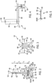
- FIGS. 1-5 illustrate one example of a tool 100 constructed in accordance with the principles of the present disclosure.
- the tool 100 is generally configured for use in easily, safely, effectively, and consistently cleaning a valve body of a control valve (e.g., a sliding-stem type control valve, a rotary control valve, or another type of control valve) after a valve trim assembly (including, e.g., a valve seat, a valve stem, and a flow control member) of the control valve and any sealing elements (e.g., gaskets, seals) employed in the control valve have been removed from the valve body for replacement or repair.
- a control valve e.g., a sliding-stem type control valve, a rotary control valve, or another type of control valve
- a valve trim assembly including, e.g., a valve seat, a valve stem, and a flow control member
- any sealing elements e.g., gaskets, seals
- the tool 100 can instead or also be used to clean the valve body of
- the tool 100 in this example generally includes a stem 104, a collar 108 coupled to the stem 104, a pair of first cleaning elements 116 carried by the collar 108, a second cleaning element 120 coupled to the stem 104, a control mechanism 124 that is coupled to the stem 104 for controlling the position of the first and second cleaning elements 116, 120, and a locking element 128 for releasably locking the tool 100 in various positions.
- the tool 100 can include more, less, or different components.
- the tool 100 may only include one first cleaning element 116 and/or multiple second cleaning elements 120.
- the tool 100 may not include the locking element 128.
- the stem 104 is generally adapted to be disposed in a valve body of a control valve. As illustrated in FIGS. 1 and 2 , the stem 104 generally extends along a longitudinal axis 132 from a first end 136 to a second end 140.
- the stem 104 in this example has four portions - a first portion 144, a second portion 148, a third portion 152, and a fourth portion 156 - each having a rectangular shape in cross-section.
- the first portion 144 defines the first end 136 and has an outer surface that, at least in this example, is not threaded.
- the second portion 148 has an outer surface that is threaded, at least in this example, and has an outer diameter that is larger than an outer diameter of the outer surface of the first portion 144.
- the third portion 152 has an outer surface that is not threaded, at least in this example, and has an outer diameter that is slightly larger than or equal to the outer diameter of the outer surface of the second portion 148.
- the fourth portion 156 defines the second end 140 and has an outer surface that is threaded, at least in this example.
- the stem 104 can be shaped, sized, or oriented differently, include more or less portions, the second and fourth portions 148, 156 may not be threaded, and/or the first and third portions 144, 152 may be threaded.
- the first portion 144 has a first length L 1
- the second portion 148 has a second length L 2 that is less than the first length L 1
- the third portion 152 has a third length L 3 that is greater than the first length L 1 and the second length L 2
- the fourth portion 156 has a fourth length L 4 that is less than each of the first, second, and third lengths L 1 , L 2 , and L 3 .
- the first, second, third, and fourth lengths L 1 , L 2 , L 3 , and L 4 may vary.
- the total length of the stem 104 (L 1 +L 2 + L 3 +L 4 ) may be adjustable in order to accommodate different sized control valves.
- the length L 1 of the first portion 144 may be increased or decreased by rotating the first portion 144 relative to the second portion 148.
- the stem 104 also includes first and second apertures 160, 162 that extend through different portions of the first portion 144 along transverse axes 164, 166, respectively, that are perpendicular to the longitudinal axis 132 (and parallel to one another).
- the first aperture 160 is positioned proximate to, but spaced from, the first end 136, while the second aperture 162 is positioned closer to the second end 140 and is positioned proximate to but spaced from the second portion 148.
- the first and second apertures 160, 162 are sized to receive the locking element 128 to lock the stem 104, and more generally the tool 100, in a respective desired position.
- the collar 108 is removably coupled to and extends outward from a portion of the stem 104, such that the collar 108 extends from a first end 168 to a second end 172 along a transverse axis 176 that is perpendicular to the longitudinal axis 132.
- the collar 108 in this example has a body 180 having an inner surface that defines a bore 182 that is sized to receive a portion of the stem 104.
- the body 180 has a rectangular shape in cross-section and the inner surface of the body 180 is threaded, such that the collar 108 can be coupled to the stem 104 by threadingly engaging the inner surface of the collar 108 to the (threaded) outer surface of the fourth portion 156 of the stem 104.
- the collar 108 may have a different size and/or shape, may be threaded to a different portion of the stem 104, or may be coupled to the stem 104 in a different manner (e.g., the collar 108 may be fixed to the stem 104).
- the first cleaning elements 116 in this example take the form of a pair of rectangularly-shaped cleaning pads carried by the collar 108 via a pair of first legs 184, respectively.
- Each of the cleaning pads has an outer surface 186 that includes, and is preferably coated with, a cleaning substance, e.g., emery, which facilitates cleaning of a sealing surface of the valve body.
- a cleaning substance e.g., emery
- the outer surface 186 of each of the first cleaning elements 116 may be referred to herein as a cleaning surface of the respective first cleaning element 116.
- the cleaning surfaces 186 may be removably coupled to the cleaning pads, respectively, such that the cleaning surfaces 186 can be removed and replaced with second cleaning surfaces 186 that are new (when the original cleaning surfaces 186 are worn out), include one or more different cleaning substances (to effectively clean control valves made of different materials), and/or are larger or smaller than the original cleaning surfaces 186 (so as to effectively clean differently sized control valves).
- Each of the first legs 184 has a first end 188, a second end 192 opposite the first end 188, and first and second intermediate portions 196, 200 extending therebetween.
- each first leg 184 is rotatably coupled to the collar 108 via a pin 204, and the second end 192 of each first leg 184 is fixedly coupled to a respective one of the cleaning elements 116 via a pin 208.
- the intermediate portions 196, 200 are angled relative to one another.
- the first cleaning elements 116 are rotatable relative to the collar 108, about the pins 204, respectively, in an arc-like manner.
- the first cleaning elements 116 can be moved toward or away from the longitudinal axis 132 between an expanded position (shown in FIG. 1 ) and a retracted position (shown in FIG. 6 ), which, at least in this example, is the default position of the first cleaning elements 116.
- the first intermediate portion 196 extends along an axis that is coaxial with the longitudinal axis 132
- the second intermediate portion 200 extends along an axis that is oriented at an angle of between approximately 0 degrees and approximately 90 degrees relative to the longitudinal axis 132, such that the first cleaning elements 116 are arranged radially outward of the profile of the collar 108 and extend along an axis that is parallel to the longitudinal axis 132.
- the first and second intermediate portions 196, 200 each extend along an axis that is oriented at an angle relative to the longitudinal axis 132, such that the first cleaning elements 116 extend along an axis that is oriented at an angle of between approximately 0 degrees and approximately 90 degrees relative to the longitudinal axis 132 and at least a portion of each of the first cleaning elements 116 is arranged between the first and second ends 168, 172 of the collar 108 (i.e., within the profile of the collar 108).
- the first cleaning elements 116 can vary in number, shape, size, or arrangement. As an example, one first cleaning element 116 or more than two first cleaning elements 116 may be employed, in which case one or more than two outer surfaces 186 may be utilized. Moreover, in other examples, the first cleaning elements 116 can be carried by the collar 108 via a single leg 184, more than two legs 184, or one or more differently sized or shaped.
- the second cleaning element 120 in this example takes the form of a sleeve having a base portion 250 and a pair of legs 254 that extend outward (downward in FIGS. 1 and 3 ) from the base portion 250.
- the base portion 250 has a rectangular shape defined by a top surface 251 and a bottom surface 252 opposite the top surface 251.
- the bottom surface 252 includes, and is preferably coated with, a cleaning substance, e.g., emery, which facilitates cleaning of a sealing surface of the valve body.
- the bottom surface 252 may also be referred to herein as a cleaning surface of the second cleaning element 120.
- the cleaning surface 252 may be removed and replaced with different cleaning surfaces, respectively.
- the legs 254 each have an irregular shape that extends along a longitudinal axis 258 coaxial with the longitudinal axis 132, widens as the legs 254 extend away from the bottom surface 252 of the base portion 250, and then tapers before terminating at ends 262.
- the base portion 250 may have a different shape (e.g., a cylindrical shape) and/or the legs 254 may have a different shape.
- the second cleaning element 120 also includes a bore 266 and a pair of slots 270.
- the bore 266 extends through the sleeve along a longitudinal axis 268.
- the bore 266 has a first portion 274 that is formed in the base portion 250 and is sized to receive a portion of the stem 104, and a second portion 278 that is formed between the pair of legs 204 and sized to receive another portion of the stem 104.
- the first portion 274 of the bore 266 has a diameter that is smaller than a diameter of the second portion 278 of the bore 266, though this need not be the case.
- the pair of slots 270 are formed in the base portion 250, and, more particularly, in the top surface 251 of the base portion 250.
- each slot 270 in this example has a substantially rectangular shape in cross-section, though in other examples, the shape of the slots 270 can vary (e.g., can be cylindrical).
- the second cleaning element 120 may vary in size, shape, or arrangement.
- the base portion 250 may have a different shape or the second cleaning element 120 may include only one leg 254, more than two legs 254, or one or more different legs.
- the second cleaning element 120 may include multiple cleaning surfaces 252.
- the second cleaning element 120 may only include one slot 270 or may include more than two slots 270.
- the control mechanism 124 in this example includes a lever 300 and a handle 304 that is coupled to the lever 300.
- the lever arm 300 in this example is an L-shaped arm that extends along a transverse axis 308 from a first end 312 to a second end 316.
- a bore 320 and an opening 324 are formed in the lever 300 proximate to the second end 316 of the lever 300.
- the bore 320 extends along a longitudinal axis 328 that is perpendicular to the transverse axis 308, and is sized to receive a portion of the stem 104.
- the opening 324 also extends along the longitudinal axis 328, as the opening 324 extends, or is defined, between the bore 320 and a pair of projections 332 that extend outward (downward in FIG. 4 ) from the lever 300. As illustrated, the opening 324 has a larger diameter than the bore 320. The opening 324 is thus sized to receive a larger diameter portion of the stem 104 than the bore 320.
- the handle 304 in this example is a manually actuated handle that is coupled to the lever 300 proximate to the first end 312 of the lever 300, such that the handle 304 extends outward (upward in FIG. 4 ) from the lever 300 along a longitudinal axis 336 that is spaced from but parallel to the longitudinal axis 328.
- the handle 304 may be coupled to the lever 300 via a rod 340 extending through the handle 304 and disposed in an aperture (not shown) formed in the lever 300, as illustrated in FIG. 4 , or in some other manner.
- control mechanism 124 can vary from what is illustrated.
- the lever 300 and/or the handle 304 can, for example, vary in shape, size, and/or configuration.
- the manual control mechanism 124 illustrated in FIGS. 1 and 4 can be replaced with an automatic control mechanism.
- a chuck feature can be fixed onto the first portion 144 of the stem 104 so as to facilitate attachment of a power tool or other automatic control mechanism to the stem 104.
- the manual control mechanism 124 can be extendable or retractable in order to accommodate various designs, various environments, and various operators.
- the locking element 128 in this example takes the form of a locking pin having a shaft 344.
- the shaft 344 has a rectangular or substantially rectangular shape that extends from a first end 348 to a second end 352 along an axis 356.
- the shaft 344 has an enlarged head 360 at the first end 348, as well as a pair of outwardly projecting fins 364 formed at or proximate the second end 352.
- the fins 364 are generally arranged to interferingly engage a portion of the lever 300 when the locking element 128 is disposed in one of the apertures 160, 162 in order to securely couple the locking element 128 to the stem 104 (and vice-versa).
- the locking pin may also include a gripping element 368 (e.g., a ring) that is coupled to the enlarged head 360 so as to facilitate insertion of the locking pin into the desired aperture 160, 162 and removal of the locking pin from the aperture 160, 162.
- a gripping element 368 e.g., a ring
- the components of the tool 100 may be assembled as illustrated in FIG. 1 , it will be appreciated that the components of the tool 100 are generally configured to be assembled in connection with a valve body of a control valve, e.g., the valve body 400 illustrated in FIGS. 6 and 7 , after a valve trim assembly of the control valve has been removed for replacement or repair.
- a valve body of a control valve e.g., the valve body 400 illustrated in FIGS. 6 and 7
- the valve body 400 generally includes an inlet 404, an outlet 408, and a fluid flow passageway 412 extending between the inlet 404 and the outlet 408.
- the valve body 400 also generally includes a first, annular sealing surface 416 and a second, annular sealing surface 420. While not illustrated herein, the first sealing surface 416 is generally arranged to receive an annular surface of a bonnet that is not shown but carries the valve trim assembly when the valve trim assembly is installed in the valve body 400.
- the second sealing surface 420 defines an annular valve port 424 through which fluid flowing through the fluid flow passageway 412 passes. While not illustrated herein, the annular valve port 424 is arranged to receive a valve seat of the valve trim assembly when the valve trim assembly is installed in the valve body 400.
- the components of the tool 100 can be assembled together in a pre-cleaning or assembled configuration, as illustrated in FIG. 6 . Once assembled, the tool 100 can be moved from the assembled configuration shown in FIG. 6 to the cleaning configuration shown in FIG. 7 . When the tool 100 is in the cleaning configuration shown in FIG. 7 , the tool 100 can be used to safely, efficiently, effectively, and consistently clean the first and second sealing surfaces 416, 420 of the valve body 400.
- the components of the tool 100 are assembled in the order described below, though in other examples, the components may be assembled in a different manner.
- the second cleaning element 120 is loosely coupled to the stem 104, particularly the second portion 148 of the stem 104, such that the second cleaning element 120 is retained on the stem 104 and the axis 268 is co-axial with the axis 132, but the first cleaning elements 116 are in their retracted position. In this example, this is accomplished by loosely threading the inner surface of the second cleaning element 120 to the outer surface of the second portion 148 of the stem 104.
- the loosely coupled together stem 104 and second cleaning element 120 are disposed in the valve body 400 so that the cleaning surface 252 of the second cleaning element 120 is seated against the first sealing surface 416 of the valve body 400, but the first cleaning elements 116 are spaced from the second sealing surface 420 of the valve body 400 (not shown).
- the stem 104 (which is loosely coupled to the second cleaning element 120) is coupled to the control mechanism 124 such that the axis 132 is co-axial with the axis 328 and parallel to but spaced from the axis 336.
- this is accomplished by positioning the stem 104 or the control mechanism 124 so that the first portion 144 of the stem 104 is disposed in or received by the bore 320 of the lever 300, and disposing (e.g., inserting) the locking element 128 into the first aperture 160 of the stem 104, as illustrated in FIG. 6 .
- the second portion 148 of the stem 104 is disposed in or received by the opening 324 of the lever 300, and the projections 332 are aligned with but spaced from the slots 270 formed in the second cleaning element 120, as is also illustrated in FIG. 6 .
- the tool 100 With the components of the tool 100 so assembled and the tool 100 coupled to the valve body 400, the tool 100 can be manipulated from the pre-cleaning configuration shown in FIG. 6 to the cleaning configuration shown in FIG. 7 to clean the first and second sealing surfaces 416, 420 of the valve body 400. It will be appreciated that in this example, the tool 100 is so manipulated by an operator of the tool 100. In other examples, however, one or more of the steps may be automatically performed (e.g., by an automatic control mechanism).
- the tool 100 is initially moved in a manner that tightens the connection between the stem 104 and the second cleaning element 120 and drives the first cleaning elements 116 toward and into engagement with the second sealing surface 420 of the valve body 400.
- this is accomplished by actuating (e.g., rotating) the handle 304 in a counterclockwise direction, which in turn rotates the lever 300 and the stem 104 (coupled to the lever 300) in the counterclockwise direction, moving the stem 104 (upward) relative to the second cleaning element 120.
- the stem 104 moves upward relative to the second cleaning element 120, the first ends 188 of the first legs 184 move upward, toward the base portion 250 of the second cleaning element 120, and along the tapered portions of the second legs 254, respectively.
- This movement drives the first cleaning elements 116 from the retracted position shown in FIG. 6 to the expanded position shown in FIG 7 .
- this movement drives the cleaning surfaces 186 of each cleaning element 116 toward and into engagement with the second sealing surface 420 of the valve body 400.
- the handle 304 is moved in the described manner until the cleaning elements 116 tightly engage the second sealing surface 420 of the valve body, such that there is sufficient pressure or force to effectively clean the second sealing surface 420.
- the locking element 128 is removed from the first aperture 160 by, for example, pulling on the gripping element 368 of the locking element 128.
- the handle 304 can be manipulated so that the projections 332 extending from the lever 300 are moved toward and into the slots 270 of the second cleaning element 120, as illustrated in FIG. 7 .
- an operator of the tool 100 moves the projections 332 toward and into the slots 270 by lowering the handle 304.
- the locking element 128 is inserted into the second aperture 162 of the stem 104, thereby securing the control mechanism 124 in the position shown in FIG. 7 .
- the handle 304 can be rotated, by the operator, in a clockwise or a counterclockwise direction (whichever direction provides the best clean and/or is most convenient to the operator). And as the handle 304 rotates, the cleaning surfaces 186 of the first cleaning elements 116 scrub the second sealing surface 420 of the valve body 400 and the cleaning surface 252 of the second cleaning element 120 scrubs the first sealing surface 416 of the valve body 400, thereby cleaning the first and second sealing surfaces 416, 420.
- the tool 100 may be decoupled from the valve body 400 and disassembled in a similar, but opposite manner. More particularly, the locking element 128 is removed from the second aperture 162, which allows the lever 300 and the handle 304 to be manipulated (e.g., lifted) so that the projections 332 are removed from the slots 270 and moved away from the slots 270. The locking element 128 can, in turn, be inserted back into the first aperture 160, at which time the tool 100 can be moved in a manner that loosens the connection between the stem 104 and the second cleaning element 120 and drives the first cleaning elements 116 out of engagement with and away from the second sealing surface 420 of the valve body 400.
- this is accomplished by rotating the handle 304 in a clockwise direction, which in turn rotates the lever 300 and the stem 104 (coupled to the lever 300) in the clockwise direction, moving the stem 104 (downward) relative to the second cleaning element 120.
- the stem 104 moves downward relative to the second cleaning element 120
- the first ends 188 of the first legs 184 move downward, away from the base portion 250 of the second cleaning element 120.
- the connection between the stem 104 and the second cleaning element 120 is sufficiently loosened (e.g., the first cleaning elements 116 are in their retracted position)
- the components of the tool 100 may be removed from the valve body 400.
- the process of removing the components of the tool 100 may be done in one step or in multiple steps (e.g., by first decoupling the control mechanism 124 from the stem 104 and then removing the stem 104 and the second cleaning element 120 from the valve body 400).
- the tool 100 can be used to clean only one of the sealing surfaces 416, 420, other sealing surfaces of the valve body 400, other surfaces of the valve body 400 (e.g., a guide surface of the valve body 400 such as the guide surface that engages a perimeter of the second cleaning element 120), or one or more sealing surfaces of other valve bodies.
- the components of the tool 100 may vary in shape and/or size in order to accommodate those different valve bodies (and/or to accommodate different valve trim assemblies).
Landscapes
- Engineering & Computer Science (AREA)
- Mechanical Engineering (AREA)
- Cleaning Implements For Floors, Carpets, Furniture, Walls, And The Like (AREA)
- Cleaning In General (AREA)
- Lift Valve (AREA)
Claims (13)
- Outil (100) de nettoyage de première et seconde surfaces d'étanchéité (420, 416) d'un corps de soupape (400), l'outil (100) comprenant :une tige (104) adaptée pour être disposée dans un corps de soupape (400) ;au moins un premier élément de nettoyage (116) couplé à une première portion de la tige (104), l'au moins un premier élément de nettoyage (116) comprenant au moins une première surface de nettoyage (186) adaptée pour mettre en prise la première surface d'étanchéité (420) lorsque la tige (104) est disposée dans le corps de soupape (400) ;au moins une première branche (184) couplée à la tige (104) et s'étendant vers l'extérieur depuis celle-ci, dans lequel l'au moins un premier élément de nettoyage (116) est couplé à la tige (104) via l'au moins une première branche (184) ;au moins un second élément de nettoyage (120) couplé à une seconde portion de la tige (104), l'au moins un second élément de nettoyage (120) comprenant au moins une seconde surface de nettoyage (252) adaptée pour mettre en prise la seconde surface d'étanchéité (416)lorsque la tige (104) est disposée dans ledit corps de soupape (400) ;une poignée (304) couplée en fonctionnement à l'au moins un premier élément de nettoyage (116) via la tige (104), dans lequel l'au moins un premier élément de nettoyage (116) est sensible de manière mobile à l'actionnement de la poignée (304) de sorte que l'au moins une première surface de nettoyage (186) nettoie ladite première surface d'étanchéité (420) du corps de soupape (400) ;dans lequel la poignée (304) est couplée en fonctionnement à l'au moins un second élément de nettoyage (120) via la tige (104), dans lequel l'au moins un second élément de nettoyage (120) est sensible de manière mobile à l'actionnement de la poignée (304) de sorte que l'au moins une seconde surface de nettoyage (252) nettoie la seconde surface d'étanchéité (416) dudit corps de soupape (400) ; etdans lequel la tige (104) inclut des première et seconde ouvertures (160, 162) correspondant aux première et seconde positions de la tige (104) par rapport à la poignée (304) respectivement, et comprenant en outre un élément de verrouillage (128) configuré pour être disposé de manière amovible dans la première ou seconde ouverture (160, 162) pour fixer la tige (104) dans la première ou seconde position respectivement.
- Outil (100) selon la revendication 1, comprenant en outre un levier (300) couplé à la poignée (304) et à la tige (104).
- Outil (100) selon la revendication 2, dans lequel le levier (300) comprend une ouverture (324), et dans lequel la tige présente une extrémité (136) disposée de manière amovible dans l'ouverture (324) du levier (300).
- Outil (100) selon une revendication précédente, comprenant en outre un levier (300) couplé à la poignée (304) et à la tige (104), dans lequel l'au moins un élément de nettoyage (120) comprend un manchon avec au moins une fente (270), et dans lequel le levier (300) comprend au moins une saillie (332) s'étendant vers l'extérieur agencée afin d'être disposée de manière amovible dans l'au moins une fente (270).
- Outil (100) selon la revendication 1, comprenant en outre un collier (108) couplé à la tige (104), le collier (108) portant l'au moins une première branche (184), dans lequel l'au moins une première branche (184) est rotative par rapport au collier (108) pour déplacer l'au moins un premier élément de nettoyage (116) entre une position rétractée, espacée de la première surface d'étanchéité (420) dudit corps de soupape (400), et une position étendue, en prise avec ladite première surface d'étanchéité (420) dudit corps de soupape (400).
- Outil selon une revendication précédente, dans lequel l'au moins un second élément de nettoyage (120) comprend un manchon avec une portion de base (250), au moins une seconde branche (254) s'étendant vers l'extérieur depuis la portion de base (250), la portion de base (250) portant l'au moins une seconde surface de nettoyage (252).
- Outil selon la revendication 6, comprenant en outre un levier (300) couplé à la poignée (304) et à la tige (104), dans lequel l'au moins un second élément de nettoyage (120) comprend au moins une fente (270) formée dans la portion de base (250) du manchon, et dans lequel le levier (300) comprend au moins une saillie (332) s'étendant vers l'extérieur agencée afin d'être disposée de manière amovible dans l'au moins une fente (270).
- Procédé de nettoyage de première et seconde surfaces d'étanchéité (420, 416) d'un corps de soupape (400), le procédé comprenant les étapes :fournir un corps comprenant une tige (104) et au moins un premier élément de nettoyage (116) couplé à une première portion de la tige (104) et portant au moins une première surface de nettoyage (186), dans lequel l'au moins un premier élément de nettoyage (116) est couplé à la tige (104) via au moins une première branche (184) couplée à la tige (104) et s'étendant vers l'extérieur depuis celle-ci ;fournir au moins un second élément de nettoyage (120) portant au moins une seconde surface de nettoyage (252) ;coupler l'au moins un second élément de nettoyage (120) à une seconde portion de la tige (104) de sorte que l'au moins un premier élément de nettoyage (116) soit dans une position rétractée ;disposer la tige (104), de l'au moins un premier élément de nettoyage (116) et de l'au moins un second élément de nettoyage (120) dans ledit corps de soupape (400) de sorte que (i) l'au moins une première surface de nettoyage (186) soit à proximité mais espacée de la première surface d'étanchéité (420), et (ii) l'au moins une seconde surface de nettoyage (252) mette en prise la seconde surface d'étanchéité (416) dudit corps de soupape ;déplacer l'au moins un premier élément de nettoyage (116) de la position rétractée dans une position étendue, dans laquelle l'au moins une première surface de nettoyage (186) met en prise la première surface d'étanchéité (420) dudit corps de soupape (400) ; etmanipuler l'au moins une première surface de nettoyage (186) et de l'au moins une seconde surface de nettoyage (252) pour nettoyer les première et seconde surfaces d'étanchéité (420, 416) dudit corps de soupape (400).
- Procédé selon la revendication 8, comprenant en outre la fourniture d'un mécanisme de commande (124) comprenant un levier (300) et une poignée (304) couplée au levier (300), et couplant le levier (300) à la tige (104), dans lequel le déplacement de l'au moins un premier élément de nettoyage (116) de la position rétractée dans la position étendue comprend la rotation de la poignée (304) par rapport à l'au moins un second élément de nettoyage (120).
- Procédé selon la revendication 9, comprenant en outre le déplacement de l'au moins une saillie (332) du levier (300) dans au moins une fente (270) formée dans l'au moins un second élément de nettoyage (120).
- Procédé selon l'une des revendications 8 à 10, dans lequel la manipulation de l'au moins une première surface de nettoyage (186) et de l'au moins une seconde surface de nettoyage (252) comprend la rotation de la poignée (304).
- Procédé selon l'une des revendications 8 à 11, comprenant en outre avant l'étape de manipulation, l'insertion d'un élément de verrouillage (128) dans une ouverture (160, 162) formée dans la tige (104).
- Procédé selon l'une des revendications 8 à 12, dans lequel le couplage de l'au moins un second élément de nettoyage (120) à la tige (104) de sorte que l'au moins un premier élément de nettoyage (116) soit dans une position rétractée comprend l'enfilage lâche de l'au moins un second élément de nettoyage (120) sur la tige (104), et dans lequel le déplacement de l'au moins un premier élément de nettoyage (116) de la position rétractée dans la position étendue comprend l'enfilage serré de l'au moins un second élément de nettoyage (120) sur la tige (104).
Applications Claiming Priority (2)
| Application Number | Priority Date | Filing Date | Title |
|---|---|---|---|
| US15/721,204 US10926299B2 (en) | 2017-09-29 | 2017-09-29 | Tool and method for cleaning a valve body of a control valve |
| PCT/US2018/050697 WO2019067215A1 (fr) | 2017-09-29 | 2018-09-12 | Outil et procédé de nettoyage du corps d'une soupape de commande |
Publications (2)
| Publication Number | Publication Date |
|---|---|
| EP3687708A1 EP3687708A1 (fr) | 2020-08-05 |
| EP3687708B1 true EP3687708B1 (fr) | 2024-08-28 |
Family
ID=63722788
Family Applications (1)
| Application Number | Title | Priority Date | Filing Date |
|---|---|---|---|
| EP18782267.1A Active EP3687708B1 (fr) | 2017-09-29 | 2018-09-12 | Outil et procédé de nettoyage du corps d'une soupape de commande |
Country Status (6)
| Country | Link |
|---|---|
| US (1) | US10926299B2 (fr) |
| EP (1) | EP3687708B1 (fr) |
| CN (2) | CN109571220B (fr) |
| CA (1) | CA3076534A1 (fr) |
| RU (1) | RU2020112911A (fr) |
| WO (1) | WO2019067215A1 (fr) |
Families Citing this family (6)
| Publication number | Priority date | Publication date | Assignee | Title |
|---|---|---|---|---|
| US10926299B2 (en) * | 2017-09-29 | 2021-02-23 | Fisher Controls International Llc | Tool and method for cleaning a valve body of a control valve |
| CN110376278B (zh) * | 2019-08-20 | 2023-04-25 | 上海圣克赛斯液压股份有限公司 | 一种阀体检测方法 |
| CN112879578B (zh) * | 2021-01-06 | 2022-04-29 | 河北化工医药职业技术学院 | 一种基于物联网的防擦伤的易于清洁的智能型闸阀 |
| CN114178253B (zh) * | 2021-05-18 | 2022-09-23 | 西派集团有限公司 | 一种阀门清洗机自动上料装置 |
| CN117139257B (zh) * | 2023-10-26 | 2024-02-13 | 泰州市百冠泵阀科技有限公司 | 一种泵阀阀块加工清洁处理设备 |
| CN120100918B (zh) * | 2025-05-09 | 2025-08-05 | 福建亿林节能设备股份有限公司 | 一种暖气管道自动调节温控阀 |
Citations (3)
| Publication number | Priority date | Publication date | Assignee | Title |
|---|---|---|---|---|
| US1420714A (en) * | 1920-03-03 | 1922-06-27 | Edward A Lee | Bottle cleaner |
| US3336617A (en) * | 1965-01-12 | 1967-08-22 | John M Bosko | Paint brush holder with telescopic handle sections |
| JPH04145281A (ja) * | 1990-10-08 | 1992-05-19 | Chubu Electric Power Co Inc | 弁体及び弁座の摺合せ装置 |
Family Cites Families (15)
| Publication number | Priority date | Publication date | Assignee | Title |
|---|---|---|---|---|
| FR5654E (fr) | 1905-06-22 | 1906-06-01 | Etienne Barlerin | Appareil à nettoyer les tonneaux |
| US2037870A (en) * | 1935-01-14 | 1936-04-21 | Thomas H Whisler | Device for cleaning and washing containers |
| US3133298A (en) * | 1963-01-18 | 1964-05-19 | James C Norwood | Plastic brush for washing inside of bottles |
| US4512810A (en) * | 1984-01-18 | 1985-04-23 | International Harvester Company | Bolster pin and method for cleaning flask bushing |
| US5709003A (en) | 1996-05-08 | 1998-01-20 | Batch; Charles W. | Crank arm cleaning brush with scrub pad |
| SE526585C2 (sv) | 2003-06-10 | 2005-10-11 | Markaryds Metallarmatur Ab | Självrensande ventil |
| CN2860734Y (zh) * | 2005-12-10 | 2007-01-24 | 大庆石油管理局 | 高压截止阀手动研磨工具 |
| US8701553B2 (en) | 2010-02-11 | 2014-04-22 | James H. McCarter | Valve system |
| US8479343B2 (en) * | 2010-05-12 | 2013-07-09 | Matthew J. Smetana | Rotatable container interior cleaning mechanism |
| WO2012038719A1 (fr) | 2010-09-20 | 2012-03-29 | Ali Waqar Majeed | Dispositif de nettoyage |
| CN201913537U (zh) * | 2010-12-07 | 2011-08-03 | 上海诺玛液压系统有限公司 | 一种用于研磨密封面的工装 |
| FR2977516B1 (fr) | 2011-07-06 | 2013-08-02 | Renault Sa | Outil pour le nettoyage d'une broche rotative |
| KR20170002419U (ko) * | 2015-12-24 | 2017-07-05 | 주식회사 한국가스기술공사 | 증발가스 압축기 실린더의 실링부 연마장치 |
| WO2017214622A1 (fr) | 2016-06-10 | 2017-12-14 | Wolf Jeffrey A | Dispositif de lavage de récipients |
| US10926299B2 (en) * | 2017-09-29 | 2021-02-23 | Fisher Controls International Llc | Tool and method for cleaning a valve body of a control valve |
-
2017
- 2017-09-29 US US15/721,204 patent/US10926299B2/en active Active
-
2018
- 2018-09-12 RU RU2020112911A patent/RU2020112911A/ru unknown
- 2018-09-12 CA CA3076534A patent/CA3076534A1/fr active Pending
- 2018-09-12 WO PCT/US2018/050697 patent/WO2019067215A1/fr not_active Ceased
- 2018-09-12 EP EP18782267.1A patent/EP3687708B1/fr active Active
- 2018-09-29 CN CN201811148324.4A patent/CN109571220B/zh active Active
- 2018-09-29 CN CN201821606188.4U patent/CN209615130U/zh active Active
Patent Citations (3)
| Publication number | Priority date | Publication date | Assignee | Title |
|---|---|---|---|---|
| US1420714A (en) * | 1920-03-03 | 1922-06-27 | Edward A Lee | Bottle cleaner |
| US3336617A (en) * | 1965-01-12 | 1967-08-22 | John M Bosko | Paint brush holder with telescopic handle sections |
| JPH04145281A (ja) * | 1990-10-08 | 1992-05-19 | Chubu Electric Power Co Inc | 弁体及び弁座の摺合せ装置 |
Also Published As
| Publication number | Publication date |
|---|---|
| US10926299B2 (en) | 2021-02-23 |
| WO2019067215A1 (fr) | 2019-04-04 |
| CN209615130U (zh) | 2019-11-12 |
| CA3076534A1 (fr) | 2019-04-04 |
| US20190099785A1 (en) | 2019-04-04 |
| RU2020112911A (ru) | 2021-10-29 |
| RU2020112911A3 (fr) | 2022-04-14 |
| CN109571220A (zh) | 2019-04-05 |
| EP3687708A1 (fr) | 2020-08-05 |
| CN109571220B (zh) | 2022-09-02 |
Similar Documents
| Publication | Publication Date | Title |
|---|---|---|
| EP3687708B1 (fr) | Outil et procédé de nettoyage du corps d'une soupape de commande | |
| US6681793B2 (en) | Top-entry ball valve assembly having camming surfaces | |
| RU2162018C2 (ru) | Блокирующийся многоцелевой пневматический инструмент | |
| JP6322494B2 (ja) | 流体制御器 | |
| CA3112962C (fr) | Outil d'enlevement de cartouche de robinet | |
| US9765902B2 (en) | Sanitary high pressure aerator valve assembly | |
| JP6667457B2 (ja) | 弁と弁座挿入および抽出ツールを伴う弁 | |
| US20120198674A1 (en) | Removal Tool | |
| MX2013013103A (es) | Aparato de control de flujo de multiples piezas para su uso con valvulas de fluidos. | |
| CA3077166A1 (fr) | Pointe d'obturateur de soupape remplacable | |
| JP6226789B2 (ja) | フィルタレギュレータ | |
| US2796881A (en) | Faucets with removable plungers | |
| US20130089382A1 (en) | Coolant supply for a machine tool | |
| US2767600A (en) | Machine for drilling and tapping mains | |
| RU2716799C1 (ru) | Устройство для отключения бокового отвода | |
| US10975894B2 (en) | Filter retaining plug | |
| EP1651893B1 (fr) | Soupape a bille controlable facile a entretenir et a reparer | |
| CN222972086U (zh) | 一种用于拆卸节流阀的油嘴的装置 | |
| WO2019162734A1 (fr) | Remplacement de virole | |
| US20080053495A1 (en) | Fluid cleaning system | |
| US3520379A (en) | Coupling type grease gun feed unit | |
| US379351A (en) | weiss | |
| CN120251783A (zh) | 用于在流体控制阀工作的同时维护该流体控制阀的内部的组件 | |
| KR20040100317A (ko) | 반도체 제조용 가스공급장치 | |
| PL177480B1 (pl) | Przyrząd do demontażu i montażu głowic zaworów odcinających |
Legal Events
| Date | Code | Title | Description |
|---|---|---|---|
| STAA | Information on the status of an ep patent application or granted ep patent |
Free format text: STATUS: UNKNOWN |
|
| STAA | Information on the status of an ep patent application or granted ep patent |
Free format text: STATUS: THE INTERNATIONAL PUBLICATION HAS BEEN MADE |
|
| PUAI | Public reference made under article 153(3) epc to a published international application that has entered the european phase |
Free format text: ORIGINAL CODE: 0009012 |
|
| STAA | Information on the status of an ep patent application or granted ep patent |
Free format text: STATUS: REQUEST FOR EXAMINATION WAS MADE |
|
| 17P | Request for examination filed |
Effective date: 20200427 |
|
| AK | Designated contracting states |
Kind code of ref document: A1 Designated state(s): AL AT BE BG CH CY CZ DE DK EE ES FI FR GB GR HR HU IE IS IT LI LT LU LV MC MK MT NL NO PL PT RO RS SE SI SK SM TR |
|
| AX | Request for extension of the european patent |
Extension state: BA ME |
|
| DAV | Request for validation of the european patent (deleted) | ||
| DAX | Request for extension of the european patent (deleted) | ||
| STAA | Information on the status of an ep patent application or granted ep patent |
Free format text: STATUS: EXAMINATION IS IN PROGRESS |
|
| 17Q | First examination report despatched |
Effective date: 20210518 |
|
| REG | Reference to a national code |
Ref country code: DE Ref legal event code: R079 Free format text: PREVIOUS MAIN CLASS: B08B0001000000 Ipc: B08B0001160000 Ref country code: DE Ref legal event code: R079 Ref document number: 602018073664 Country of ref document: DE Free format text: PREVIOUS MAIN CLASS: B08B0001000000 Ipc: B08B0001160000 |
|
| GRAP | Despatch of communication of intention to grant a patent |
Free format text: ORIGINAL CODE: EPIDOSNIGR1 |
|
| STAA | Information on the status of an ep patent application or granted ep patent |
Free format text: STATUS: GRANT OF PATENT IS INTENDED |
|
| INTG | Intention to grant announced |
Effective date: 20240322 |
|
| RIC1 | Information provided on ipc code assigned before grant |
Ipc: F16K 1/44 20060101ALI20240308BHEP Ipc: B08B 9/02 20060101ALI20240308BHEP Ipc: B08B 1/32 20240101ALI20240308BHEP Ipc: B08B 1/16 20240101AFI20240308BHEP |
|
| GRAS | Grant fee paid |
Free format text: ORIGINAL CODE: EPIDOSNIGR3 |
|
| GRAA | (expected) grant |
Free format text: ORIGINAL CODE: 0009210 |
|
| STAA | Information on the status of an ep patent application or granted ep patent |
Free format text: STATUS: THE PATENT HAS BEEN GRANTED |
|
| AK | Designated contracting states |
Kind code of ref document: B1 Designated state(s): AL AT BE BG CH CY CZ DE DK EE ES FI FR GB GR HR HU IE IS IT LI LT LU LV MC MK MT NL NO PL PT RO RS SE SI SK SM TR |
|
| REG | Reference to a national code |
Ref country code: GB Ref legal event code: FG4D |
|
| REG | Reference to a national code |
Ref country code: CH Ref legal event code: EP |
|
| P01 | Opt-out of the competence of the unified patent court (upc) registered |
Free format text: CASE NUMBER: APP_46265/2024 Effective date: 20240809 |
|
| REG | Reference to a national code |
Ref country code: DE Ref legal event code: R096 Ref document number: 602018073664 Country of ref document: DE |
|
| REG | Reference to a national code |
Ref country code: IE Ref legal event code: FG4D |
|
| REG | Reference to a national code |
Ref country code: LT Ref legal event code: MG9D |
|
| PG25 | Lapsed in a contracting state [announced via postgrant information from national office to epo] |
Ref country code: NO Free format text: LAPSE BECAUSE OF FAILURE TO SUBMIT A TRANSLATION OF THE DESCRIPTION OR TO PAY THE FEE WITHIN THE PRESCRIBED TIME-LIMIT Effective date: 20241128 |
|
| REG | Reference to a national code |
Ref country code: AT Ref legal event code: MK05 Ref document number: 1717399 Country of ref document: AT Kind code of ref document: T Effective date: 20240828 |
|
| PG25 | Lapsed in a contracting state [announced via postgrant information from national office to epo] |
Ref country code: NL Free format text: LAPSE BECAUSE OF FAILURE TO SUBMIT A TRANSLATION OF THE DESCRIPTION OR TO PAY THE FEE WITHIN THE PRESCRIBED TIME-LIMIT Effective date: 20240828 Ref country code: PL Free format text: LAPSE BECAUSE OF FAILURE TO SUBMIT A TRANSLATION OF THE DESCRIPTION OR TO PAY THE FEE WITHIN THE PRESCRIBED TIME-LIMIT Effective date: 20240828 Ref country code: GR Free format text: LAPSE BECAUSE OF FAILURE TO SUBMIT A TRANSLATION OF THE DESCRIPTION OR TO PAY THE FEE WITHIN THE PRESCRIBED TIME-LIMIT Effective date: 20241129 Ref country code: PT Free format text: LAPSE BECAUSE OF FAILURE TO SUBMIT A TRANSLATION OF THE DESCRIPTION OR TO PAY THE FEE WITHIN THE PRESCRIBED TIME-LIMIT Effective date: 20241230 Ref country code: FI Free format text: LAPSE BECAUSE OF FAILURE TO SUBMIT A TRANSLATION OF THE DESCRIPTION OR TO PAY THE FEE WITHIN THE PRESCRIBED TIME-LIMIT Effective date: 20240828 |
|
| PG25 | Lapsed in a contracting state [announced via postgrant information from national office to epo] |
Ref country code: BG Free format text: LAPSE BECAUSE OF FAILURE TO SUBMIT A TRANSLATION OF THE DESCRIPTION OR TO PAY THE FEE WITHIN THE PRESCRIBED TIME-LIMIT Effective date: 20240828 |
|
| PG25 | Lapsed in a contracting state [announced via postgrant information from national office to epo] |
Ref country code: LV Free format text: LAPSE BECAUSE OF FAILURE TO SUBMIT A TRANSLATION OF THE DESCRIPTION OR TO PAY THE FEE WITHIN THE PRESCRIBED TIME-LIMIT Effective date: 20240828 |
|
| REG | Reference to a national code |
Ref country code: NL Ref legal event code: MP Effective date: 20240828 |
|
| PG25 | Lapsed in a contracting state [announced via postgrant information from national office to epo] |
Ref country code: IS Free format text: LAPSE BECAUSE OF FAILURE TO SUBMIT A TRANSLATION OF THE DESCRIPTION OR TO PAY THE FEE WITHIN THE PRESCRIBED TIME-LIMIT Effective date: 20241228 Ref country code: AT Free format text: LAPSE BECAUSE OF FAILURE TO SUBMIT A TRANSLATION OF THE DESCRIPTION OR TO PAY THE FEE WITHIN THE PRESCRIBED TIME-LIMIT Effective date: 20240828 |
|
| PG25 | Lapsed in a contracting state [announced via postgrant information from national office to epo] |
Ref country code: HR Free format text: LAPSE BECAUSE OF FAILURE TO SUBMIT A TRANSLATION OF THE DESCRIPTION OR TO PAY THE FEE WITHIN THE PRESCRIBED TIME-LIMIT Effective date: 20240828 |
|
| PG25 | Lapsed in a contracting state [announced via postgrant information from national office to epo] |
Ref country code: RS Free format text: LAPSE BECAUSE OF FAILURE TO SUBMIT A TRANSLATION OF THE DESCRIPTION OR TO PAY THE FEE WITHIN THE PRESCRIBED TIME-LIMIT Effective date: 20241128 Ref country code: ES Free format text: LAPSE BECAUSE OF FAILURE TO SUBMIT A TRANSLATION OF THE DESCRIPTION OR TO PAY THE FEE WITHIN THE PRESCRIBED TIME-LIMIT Effective date: 20240828 |
|
| PG25 | Lapsed in a contracting state [announced via postgrant information from national office to epo] |
Ref country code: RS Free format text: LAPSE BECAUSE OF FAILURE TO SUBMIT A TRANSLATION OF THE DESCRIPTION OR TO PAY THE FEE WITHIN THE PRESCRIBED TIME-LIMIT Effective date: 20241128 Ref country code: PT Free format text: LAPSE BECAUSE OF FAILURE TO SUBMIT A TRANSLATION OF THE DESCRIPTION OR TO PAY THE FEE WITHIN THE PRESCRIBED TIME-LIMIT Effective date: 20241230 Ref country code: PL Free format text: LAPSE BECAUSE OF FAILURE TO SUBMIT A TRANSLATION OF THE DESCRIPTION OR TO PAY THE FEE WITHIN THE PRESCRIBED TIME-LIMIT Effective date: 20240828 Ref country code: NO Free format text: LAPSE BECAUSE OF FAILURE TO SUBMIT A TRANSLATION OF THE DESCRIPTION OR TO PAY THE FEE WITHIN THE PRESCRIBED TIME-LIMIT Effective date: 20241128 Ref country code: NL Free format text: LAPSE BECAUSE OF FAILURE TO SUBMIT A TRANSLATION OF THE DESCRIPTION OR TO PAY THE FEE WITHIN THE PRESCRIBED TIME-LIMIT Effective date: 20240828 Ref country code: LV Free format text: LAPSE BECAUSE OF FAILURE TO SUBMIT A TRANSLATION OF THE DESCRIPTION OR TO PAY THE FEE WITHIN THE PRESCRIBED TIME-LIMIT Effective date: 20240828 Ref country code: IS Free format text: LAPSE BECAUSE OF FAILURE TO SUBMIT A TRANSLATION OF THE DESCRIPTION OR TO PAY THE FEE WITHIN THE PRESCRIBED TIME-LIMIT Effective date: 20241228 Ref country code: HR Free format text: LAPSE BECAUSE OF FAILURE TO SUBMIT A TRANSLATION OF THE DESCRIPTION OR TO PAY THE FEE WITHIN THE PRESCRIBED TIME-LIMIT Effective date: 20240828 Ref country code: GR Free format text: LAPSE BECAUSE OF FAILURE TO SUBMIT A TRANSLATION OF THE DESCRIPTION OR TO PAY THE FEE WITHIN THE PRESCRIBED TIME-LIMIT Effective date: 20241129 Ref country code: FI Free format text: LAPSE BECAUSE OF FAILURE TO SUBMIT A TRANSLATION OF THE DESCRIPTION OR TO PAY THE FEE WITHIN THE PRESCRIBED TIME-LIMIT Effective date: 20240828 Ref country code: ES Free format text: LAPSE BECAUSE OF FAILURE TO SUBMIT A TRANSLATION OF THE DESCRIPTION OR TO PAY THE FEE WITHIN THE PRESCRIBED TIME-LIMIT Effective date: 20240828 Ref country code: BG Free format text: LAPSE BECAUSE OF FAILURE TO SUBMIT A TRANSLATION OF THE DESCRIPTION OR TO PAY THE FEE WITHIN THE PRESCRIBED TIME-LIMIT Effective date: 20240828 Ref country code: AT Free format text: LAPSE BECAUSE OF FAILURE TO SUBMIT A TRANSLATION OF THE DESCRIPTION OR TO PAY THE FEE WITHIN THE PRESCRIBED TIME-LIMIT Effective date: 20240828 |
|
| REG | Reference to a national code |
Ref country code: DE Ref legal event code: R119 Ref document number: 602018073664 Country of ref document: DE |
|
| PG25 | Lapsed in a contracting state [announced via postgrant information from national office to epo] |
Ref country code: DK Free format text: LAPSE BECAUSE OF FAILURE TO SUBMIT A TRANSLATION OF THE DESCRIPTION OR TO PAY THE FEE WITHIN THE PRESCRIBED TIME-LIMIT Effective date: 20240828 Ref country code: SM Free format text: LAPSE BECAUSE OF FAILURE TO SUBMIT A TRANSLATION OF THE DESCRIPTION OR TO PAY THE FEE WITHIN THE PRESCRIBED TIME-LIMIT Effective date: 20240828 Ref country code: RO Free format text: LAPSE BECAUSE OF FAILURE TO SUBMIT A TRANSLATION OF THE DESCRIPTION OR TO PAY THE FEE WITHIN THE PRESCRIBED TIME-LIMIT Effective date: 20240828 |
|
| PG25 | Lapsed in a contracting state [announced via postgrant information from national office to epo] |
Ref country code: EE Free format text: LAPSE BECAUSE OF FAILURE TO SUBMIT A TRANSLATION OF THE DESCRIPTION OR TO PAY THE FEE WITHIN THE PRESCRIBED TIME-LIMIT Effective date: 20240828 |
|
| PG25 | Lapsed in a contracting state [announced via postgrant information from national office to epo] |
Ref country code: CZ Free format text: LAPSE BECAUSE OF FAILURE TO SUBMIT A TRANSLATION OF THE DESCRIPTION OR TO PAY THE FEE WITHIN THE PRESCRIBED TIME-LIMIT Effective date: 20240828 |
|
| PG25 | Lapsed in a contracting state [announced via postgrant information from national office to epo] |
Ref country code: IT Free format text: LAPSE BECAUSE OF FAILURE TO SUBMIT A TRANSLATION OF THE DESCRIPTION OR TO PAY THE FEE WITHIN THE PRESCRIBED TIME-LIMIT Effective date: 20240828 Ref country code: SK Free format text: LAPSE BECAUSE OF FAILURE TO SUBMIT A TRANSLATION OF THE DESCRIPTION OR TO PAY THE FEE WITHIN THE PRESCRIBED TIME-LIMIT Effective date: 20240828 |
|
| REG | Reference to a national code |
Ref country code: CH Ref legal event code: PL |
|
| PG25 | Lapsed in a contracting state [announced via postgrant information from national office to epo] |
Ref country code: LU Free format text: LAPSE BECAUSE OF NON-PAYMENT OF DUE FEES Effective date: 20240912 |
|
| PLBE | No opposition filed within time limit |
Free format text: ORIGINAL CODE: 0009261 |
|
| STAA | Information on the status of an ep patent application or granted ep patent |
Free format text: STATUS: NO OPPOSITION FILED WITHIN TIME LIMIT |
|
| PG25 | Lapsed in a contracting state [announced via postgrant information from national office to epo] |
Ref country code: MC Free format text: LAPSE BECAUSE OF FAILURE TO SUBMIT A TRANSLATION OF THE DESCRIPTION OR TO PAY THE FEE WITHIN THE PRESCRIBED TIME-LIMIT Effective date: 20240828 |
|
| PG25 | Lapsed in a contracting state [announced via postgrant information from national office to epo] |
Ref country code: DE Free format text: LAPSE BECAUSE OF NON-PAYMENT OF DUE FEES Effective date: 20250401 |
|
| REG | Reference to a national code |
Ref country code: BE Ref legal event code: MM Effective date: 20240930 |
|
| PG25 | Lapsed in a contracting state [announced via postgrant information from national office to epo] |
Ref country code: BE Free format text: LAPSE BECAUSE OF NON-PAYMENT OF DUE FEES Effective date: 20240930 |
|
| PG25 | Lapsed in a contracting state [announced via postgrant information from national office to epo] |
Ref country code: CH Free format text: LAPSE BECAUSE OF NON-PAYMENT OF DUE FEES Effective date: 20240930 |
|
| PG25 | Lapsed in a contracting state [announced via postgrant information from national office to epo] |
Ref country code: IE Free format text: LAPSE BECAUSE OF NON-PAYMENT OF DUE FEES Effective date: 20240912 |
|
| 26N | No opposition filed |
Effective date: 20250530 |
|
| PG25 | Lapsed in a contracting state [announced via postgrant information from national office to epo] |
Ref country code: SE Free format text: LAPSE BECAUSE OF FAILURE TO SUBMIT A TRANSLATION OF THE DESCRIPTION OR TO PAY THE FEE WITHIN THE PRESCRIBED TIME-LIMIT Effective date: 20240828 |
|
| PGFP | Annual fee paid to national office [announced via postgrant information from national office to epo] |
Ref country code: GB Payment date: 20250822 Year of fee payment: 8 |
|
| PGFP | Annual fee paid to national office [announced via postgrant information from national office to epo] |
Ref country code: FR Payment date: 20250820 Year of fee payment: 8 |
|
| PG25 | Lapsed in a contracting state [announced via postgrant information from national office to epo] |
Ref country code: CY Free format text: LAPSE BECAUSE OF FAILURE TO SUBMIT A TRANSLATION OF THE DESCRIPTION OR TO PAY THE FEE WITHIN THE PRESCRIBED TIME-LIMIT; INVALID AB INITIO Effective date: 20180912 |
|
| PG25 | Lapsed in a contracting state [announced via postgrant information from national office to epo] |
Ref country code: HU Free format text: LAPSE BECAUSE OF FAILURE TO SUBMIT A TRANSLATION OF THE DESCRIPTION OR TO PAY THE FEE WITHIN THE PRESCRIBED TIME-LIMIT; INVALID AB INITIO Effective date: 20180912 |