EP3687845B1 - Glaspaneel mit polymerischem rand, verstärkungsrahmen und befestigungsrahmen - Google Patents
Glaspaneel mit polymerischem rand, verstärkungsrahmen und befestigungsrahmen Download PDFInfo
- Publication number
- EP3687845B1 EP3687845B1 EP18808412.3A EP18808412A EP3687845B1 EP 3687845 B1 EP3687845 B1 EP 3687845B1 EP 18808412 A EP18808412 A EP 18808412A EP 3687845 B1 EP3687845 B1 EP 3687845B1
- Authority
- EP
- European Patent Office
- Prior art keywords
- glass panel
- frame
- reinforcement
- armatures
- armature
- Prior art date
- Legal status (The legal status is an assumption and is not a legal conclusion. Google has not performed a legal analysis and makes no representation as to the accuracy of the status listed.)
- Active
Links
Images


Classifications
-
- B—PERFORMING OPERATIONS; TRANSPORTING
- B60—VEHICLES IN GENERAL
- B60J—WINDOWS, WINDSCREENS, NON-FIXED ROOFS, DOORS, OR SIMILAR DEVICES FOR VEHICLES; REMOVABLE EXTERNAL PROTECTIVE COVERINGS SPECIALLY ADAPTED FOR VEHICLES
- B60J7/00—Non-fixed roofs; Roofs with movable panels, e.g. rotary sunroofs
- B60J7/02—Non-fixed roofs; Roofs with movable panels, e.g. rotary sunroofs of sliding type, e.g. comprising guide shoes
- B60J7/04—Non-fixed roofs; Roofs with movable panels, e.g. rotary sunroofs of sliding type, e.g. comprising guide shoes with rigid plate-like element or elements, e.g. open roofs with harmonica-type folding rigid panels
- B60J7/043—Sunroofs e.g. sliding above the roof
- B60J7/0435—Sunroofs e.g. sliding above the roof pivoting upwardly to vent mode and moving at the outside of the roof to fully open mode
-
- B—PERFORMING OPERATIONS; TRANSPORTING
- B32—LAYERED PRODUCTS
- B32B—LAYERED PRODUCTS, i.e. PRODUCTS BUILT-UP OF STRATA OF FLAT OR NON-FLAT, e.g. CELLULAR OR HONEYCOMB, FORM
- B32B17/00—Layered products essentially comprising sheet glass, or glass, slag, or like fibres
- B32B17/06—Layered products essentially comprising sheet glass, or glass, slag, or like fibres comprising glass as the main or only constituent of a layer, next to another layer of a specific material
- B32B17/10—Layered products essentially comprising sheet glass, or glass, slag, or like fibres comprising glass as the main or only constituent of a layer, next to another layer of a specific material of synthetic resin
- B32B17/10005—Layered products essentially comprising sheet glass, or glass, slag, or like fibres comprising glass as the main or only constituent of a layer, next to another layer of a specific material of synthetic resin laminated safety glass or glazing
- B32B17/10009—Layered products essentially comprising sheet glass, or glass, slag, or like fibres comprising glass as the main or only constituent of a layer, next to another layer of a specific material of synthetic resin laminated safety glass or glazing characterized by the number, the constitution or treatment of glass sheets
- B32B17/10036—Layered products essentially comprising sheet glass, or glass, slag, or like fibres comprising glass as the main or only constituent of a layer, next to another layer of a specific material of synthetic resin laminated safety glass or glazing characterized by the number, the constitution or treatment of glass sheets comprising two outer glass sheets
-
- B—PERFORMING OPERATIONS; TRANSPORTING
- B29—WORKING OF PLASTICS; WORKING OF SUBSTANCES IN A PLASTIC STATE IN GENERAL
- B29K—INDEXING SCHEME ASSOCIATED WITH SUBCLASSES B29B, B29C OR B29D, RELATING TO MOULDING MATERIALS OR TO MATERIALS FOR MOULDS, REINFORCEMENTS, FILLERS OR PREFORMED PARTS, e.g. INSERTS
- B29K2995/00—Properties of moulding materials, reinforcements, fillers, preformed parts or moulds
- B29K2995/0018—Properties of moulding materials, reinforcements, fillers, preformed parts or moulds having particular optical properties, e.g. fluorescent or phosphorescent
- B29K2995/0026—Transparent
-
- B—PERFORMING OPERATIONS; TRANSPORTING
- B32—LAYERED PRODUCTS
- B32B—LAYERED PRODUCTS, i.e. PRODUCTS BUILT-UP OF STRATA OF FLAT OR NON-FLAT, e.g. CELLULAR OR HONEYCOMB, FORM
- B32B15/00—Layered products comprising a layer of metal
- B32B15/04—Layered products comprising a layer of metal comprising metal as the main or only constituent of a layer, which is next to another layer of the same or of a different material
-
- B—PERFORMING OPERATIONS; TRANSPORTING
- B32—LAYERED PRODUCTS
- B32B—LAYERED PRODUCTS, i.e. PRODUCTS BUILT-UP OF STRATA OF FLAT OR NON-FLAT, e.g. CELLULAR OR HONEYCOMB, FORM
- B32B17/00—Layered products essentially comprising sheet glass, or glass, slag, or like fibres
- B32B17/06—Layered products essentially comprising sheet glass, or glass, slag, or like fibres comprising glass as the main or only constituent of a layer, next to another layer of a specific material
- B32B17/10—Layered products essentially comprising sheet glass, or glass, slag, or like fibres comprising glass as the main or only constituent of a layer, next to another layer of a specific material of synthetic resin
- B32B17/10005—Layered products essentially comprising sheet glass, or glass, slag, or like fibres comprising glass as the main or only constituent of a layer, next to another layer of a specific material of synthetic resin laminated safety glass or glazing
- B32B17/10165—Functional features of the laminated safety glass or glazing
- B32B17/10293—Edge features, e.g. inserts or holes
-
- B—PERFORMING OPERATIONS; TRANSPORTING
- B32—LAYERED PRODUCTS
- B32B—LAYERED PRODUCTS, i.e. PRODUCTS BUILT-UP OF STRATA OF FLAT OR NON-FLAT, e.g. CELLULAR OR HONEYCOMB, FORM
- B32B17/00—Layered products essentially comprising sheet glass, or glass, slag, or like fibres
- B32B17/06—Layered products essentially comprising sheet glass, or glass, slag, or like fibres comprising glass as the main or only constituent of a layer, next to another layer of a specific material
- B32B17/10—Layered products essentially comprising sheet glass, or glass, slag, or like fibres comprising glass as the main or only constituent of a layer, next to another layer of a specific material of synthetic resin
- B32B17/10005—Layered products essentially comprising sheet glass, or glass, slag, or like fibres comprising glass as the main or only constituent of a layer, next to another layer of a specific material of synthetic resin laminated safety glass or glazing
- B32B17/10165—Functional features of the laminated safety glass or glazing
- B32B17/10541—Functional features of the laminated safety glass or glazing comprising a light source or a light guide
-
- B—PERFORMING OPERATIONS; TRANSPORTING
- B32—LAYERED PRODUCTS
- B32B—LAYERED PRODUCTS, i.e. PRODUCTS BUILT-UP OF STRATA OF FLAT OR NON-FLAT, e.g. CELLULAR OR HONEYCOMB, FORM
- B32B2605/00—Vehicles
- B32B2605/08—Cars
-
- B—PERFORMING OPERATIONS; TRANSPORTING
- B60—VEHICLES IN GENERAL
- B60J—WINDOWS, WINDSCREENS, NON-FIXED ROOFS, DOORS, OR SIMILAR DEVICES FOR VEHICLES; REMOVABLE EXTERNAL PROTECTIVE COVERINGS SPECIALLY ADAPTED FOR VEHICLES
- B60J1/00—Windows; Windscreens; Accessories therefor
-
- B—PERFORMING OPERATIONS; TRANSPORTING
- B60—VEHICLES IN GENERAL
- B60J—WINDOWS, WINDSCREENS, NON-FIXED ROOFS, DOORS, OR SIMILAR DEVICES FOR VEHICLES; REMOVABLE EXTERNAL PROTECTIVE COVERINGS SPECIALLY ADAPTED FOR VEHICLES
- B60J1/00—Windows; Windscreens; Accessories therefor
- B60J1/004—Mounting of windows
- B60J1/007—Mounting of windows received in frames to be attached to vehicle
-
- B—PERFORMING OPERATIONS; TRANSPORTING
- B60—VEHICLES IN GENERAL
- B60J—WINDOWS, WINDSCREENS, NON-FIXED ROOFS, DOORS, OR SIMILAR DEVICES FOR VEHICLES; REMOVABLE EXTERNAL PROTECTIVE COVERINGS SPECIALLY ADAPTED FOR VEHICLES
- B60J7/00—Non-fixed roofs; Roofs with movable panels, e.g. rotary sunroofs
- B60J7/02—Non-fixed roofs; Roofs with movable panels, e.g. rotary sunroofs of sliding type, e.g. comprising guide shoes
- B60J7/024—Non-fixed roofs; Roofs with movable panels, e.g. rotary sunroofs of sliding type, e.g. comprising guide shoes characterised by the height regulating mechanism of the sliding panel
-
- B—PERFORMING OPERATIONS; TRANSPORTING
- B60—VEHICLES IN GENERAL
- B60J—WINDOWS, WINDSCREENS, NON-FIXED ROOFS, DOORS, OR SIMILAR DEVICES FOR VEHICLES; REMOVABLE EXTERNAL PROTECTIVE COVERINGS SPECIALLY ADAPTED FOR VEHICLES
- B60J7/00—Non-fixed roofs; Roofs with movable panels, e.g. rotary sunroofs
- B60J7/02—Non-fixed roofs; Roofs with movable panels, e.g. rotary sunroofs of sliding type, e.g. comprising guide shoes
- B60J7/04—Non-fixed roofs; Roofs with movable panels, e.g. rotary sunroofs of sliding type, e.g. comprising guide shoes with rigid plate-like element or elements, e.g. open roofs with harmonica-type folding rigid panels
- B60J7/043—Sunroofs e.g. sliding above the roof
Definitions
- the present invention relates to a glazed panel with a polymeric surround, reinforcing frames and fixing frames, in particular for the roof of a motor vehicle.
- the roofs of motor vehicles are subject to a depression due to the aerodynamics of the vehicle which increases with the speed of movement of the vehicle. This results in mechanical forces stressing the roof upwards: this phenomenon is usually called the windload effect.
- the roofs are equipped with a glass panel, the latter is subjected to these forces stressing the glass panel in particular in bending and must therefore be able to withstand them.
- the glass panel When mounted fixed in the roof, the glass panel is protected against excessive deformation by its attachment to the vehicle body.
- the glass panel In the case of a roof glass panel associated with a translation mechanism to form an opening, the glass panel - traditionally a toughened monolithic glass 3 to 5 mm thick - is reinforced against bending deformations caused by the windload effect by means of a longitudinal metal reinforcement secured to the glass panel along the front edge of the panel and another along the rear edge of the glass panel.
- a longitudinal metal reinforcement secured to the glass panel along the front edge of the panel and another along the rear edge of the glass panel.
- two other longitudinal metal reinforcements are secured along the side edges on the glass panel and allow the glass panel to be fixed by means of the translation mechanism in a corresponding opening made in the roof of the motor vehicle.
- the glass panel is also provided on its periphery with a polymeric material, usually polyurethane.
- the reinforcing reinforcements are usually completely encapsulated in the polymeric material and the fixing reinforcements partially, this in order to secure them to the glass panel.
- laminated glass possibly reinforced by thermal or chemical treatments, is increasingly being used.
- the latter is more flexible than monolithic glass, particularly due to its plastic interlayer.
- the current trend is to lighten the roof by reducing the thickness of the glass sheets constituting the laminated glass, which further increases the flexibility of the glass panel.
- the present invention aims to overcome this drawback.
- the invention proposes to connect two by two the two reinforcement frames and the two fixing frames by their longitudinal ends to form a frame.
- the glass panel is supported at the front and at the rear over its entire transverse part up to the fixing frames without interruption, unlike the prior art generally leaving a space of 1 to 10 mm between them, sometimes more.
- the stress concentrations in the corners of the glass panel are reduced, which makes it possible to reduce, or even exclude, the risk of breakage linked to the windload effect or during the aforementioned tests of mechanical resistance under load.
- the production in the form of a frame by forming a metal part not only involves numerous operations, in particular bending and cutting to structure the fixing frames, but also leads to a significant loss of material due to the fact that the structure of the fixing frames is lighter compared to that of the reinforcing frames because the former do not perform a reinforcing function of the glass panel or at least only incidentally.
- the assembly of the reinforcing frames and the fixing frames together by welding is also complex and expensive.
- EP 2 700 521 A2 a motor vehicle roof opening in which four separate metal reinforcement frames are secured to the inner face of the glass panel of the opening, one at the front of the glass panel, another at the rear and two others on a lateral side respectively of the glass panel.
- the lateral frames also serve to attach the opening to a translation mechanism.
- the front frame is attached to the glass panel by a rubber seal or similar arranged on the front edge of the glass panel. glass while the side frames and the rear frame are fixed to the glass panel by an adhesive.
- the four frames are arranged on the glass panel by being joined two by two at their ends each time by means of a respective intermediate piece made of plastic, and thus form a frame on the glass panel.
- the intermediate pieces made of plastic are also fixed to the glass panel by an adhesive or similar.
- Each intermediate piece has a section that is inserted into the end of a front or rear frame, the insertion being made in the longitudinal direction of the front or rear frame concerned.
- the side frames have an open U-shaped cross-section so that the end of the side frame can be freely engaged on a corresponding section of the intermediate piece in a direction perpendicular to the longitudinal direction of the side frame.
- the frames are fixed to the glass panel one after the other. This solution remains complex and tedious from the point of view of the installation of the frames on the glass panel for the purposes of securing it to the latter.
- WO 2017/152980 A1 also describes a motor vehicle roof opening whose glass panel is reinforced. It proposes in particular to produce a front reinforcement frame and a rear reinforcement frame made of plastic material reinforced with fibres and two lateral reinforcements made, as the case may be, of metal or also of plastic material reinforced with fibres.
- the reinforcements are, as the case may be, fixed to the glass panel by gluing and/or encapsulation so as to form a frame between them. It is apparent from the document that the installation of the reinforcements relative to the glass panel with a view to their securing is also carried out successively, which has the disadvantage that this solution, similar to the previous document, is complex and tedious from the point of view of the installation of the reinforcements on the glass panel with a view to securing them thereto.
- a snap-fit assembly allows the reinforcement reinforcement and the fixing reinforcement to be joined simply, quickly and economically.
- the assembly can optionally be completed, for example, by gluing or by elastic snap-fitting of the end of one of the reinforcements into that of the other or into the intermediate connecting piece, which ensures or completes the relative positioning of the two parts. If their material allows it, it can also be one or more welding points securing the two nested parts, the snap-fit simplifying the welding operation in this case.
- the assembly it is particularly advantageous for the assembly to be carried out exclusively by snap-fit because this solution is particularly simple, quick and economical. In this case, it is advantageous for the snap-fit to be carried out with a tight fit.
- the clamping level is preferably chosen to be appropriate to allow manual interlocking while providing relative positional retention of the parts involved which allows subsequent manipulation of the resulting frame without mutual disengagement.
- this method of assembly is advantageous to implement at each end of the two reinforcements.
- This makes it possible to design and manufacture the reinforcements and the fixing reinforcements independently: they can thus have their own characteristics adapted to their respective functions while facilitating their respective manufacture.
- This then makes it possible to assemble them in the form of a frame in a simple, rapid and economical manner. In particular, this avoids the aforementioned disadvantages of the molding, forming or welding solutions.
- it is possible to use different materials for the reinforcements and the fixing reinforcements for example a composite material for the reinforcements and a metallic material for the fixing reinforcements.
- the invention according to this first aspect is particularly suited to the case of glazed panels whose panel glass is laminated glass, particularly double-laminated, and has a surface area greater than or equal to 0.4 m2 because they are more exposed to the risk of breakage at the corners than smaller panels.
- the invention also provides a motor vehicle, comprising a glazed panel according to the first aspect of the invention, which is mounted in the roof of the vehicle, preferably forming an opening, the two reinforcing frames extending transversely relative to the motor vehicle.
- the glass panel can be made of one or more sheets of mineral glass, but also of one or more sheets of organic glass, for example polycarbonate or polymethyl methacrylate.
- a glazed panel 10 is an opening for a motor vehicle roof and is intended to be mounted in an opening in the roof provided for this purpose by means of a mechanism allowing it to be moved between a closed position and an open position.
- the glass panel 10 has two main faces: an upper face 15 and a lower face 16 corresponding respectively to the exterior of the vehicle and to the interior of the passenger compartment of the vehicle after mounting in the roof thereof.
- the glass panel 10 comprises a front edge 11 and a rear edge 12, as well as two side edges 13, 14.
- the concepts of front, rear and side define in this case the orientation of the glass panel after installation in the roof of the motor vehicle in correspondence with the front, rear and side sides respectively of the motor vehicle.
- the glass panel 10 comprises a glass panel 20, preferably a laminated glass, and more preferably a bilaminated glass having two glass sheets between which is arranged an interlayer of polymeric material, for example polyvinyl butyral (PVB).
- the outer glass sheet preferably has a thickness of 1.4 to 3.1 mm
- the inner glass sheet preferably has a thickness of 0.7 to 3.1 mm, more preferably 0.7 to 2.1 mm.
- interior and exterior refers respectively to the interior and exterior of the passenger compartment of the vehicle. Alternatively, it may be a monolithic glass.
- the glass panel 20 is provided over its entire periphery with a polymeric material 30. It can advantageously ensure the finishing of the periphery of the glass panel 20 and protect it against mechanical shocks.
- the edge of the glass panel 20 is preferably entirely covered by the polymeric material. 30.
- the polymeric material may also form a surface intended to cooperate with one or more seals fixed in the opening of the roof of the motor vehicle in order to ensure the seal between the roof and the glass panel in the closed position.
- the polymeric material 30 may itself carry one or more peripheral seals for this same purpose.
- parts may be integrated into the polymeric material 30 such as stops or sliding buffers, centering pins, a trim, etc.
- the polymeric material 30 is preferably polyurethane, but it may be any other suitable material, in particular a plastic material.
- the polymeric material 30 is preferably arranged on the glass panel 20 by overmolding.
- the glass panel 10 comprises a reinforcing frame 51 secured to the glass panel 20 in the region of the front edge 11 and another reinforcing frame 52 secured to the glass panel 20 in the region of the rear edge 12.
- the two reinforcing frames 51 and 52 have the function of stiffening the glass 20 to limit its bending in particular under the windload effect and thus promote the maintenance of the integrity of the glass panel 20 and the sealing between the glass panel 10 and the roof of the motor vehicle.
- the reinforcing frames 51, 52 are preferably completely encapsulated in the polymeric material 30 at the periphery of the glass panel 20.
- the glass panel 10 comprises a fixing frame 41 extending along the right edge region of the glass panel 10 and another - not visible - along the left edge region of the glass panel 10. They have a longitudinal shape - that is to say elongated - and extend substantially over the entire length of the glass panel 20. They are used to fix the glass panel 10 to an opening translation mechanism intended for mounting the glass panel 10 in an opening in the roof of a motor vehicle and allowing the glass panel 10 to be moved between an open position and a closed position.
- the fixing to the opening translation mechanism is carried out at different points between the front edge 11 and the rear edge 12 by any suitable means such as screws or rivets.
- the fixing frames 41 have openings or fixing eyes in particular for the passage of screws, rivets or other fixing elements.
- the fixing frames 41 are only partially integrated into the seal 30 to leave the fixing openings or eyelets accessible.
- the fixing frames 41 are preferably made of a metal material because it is more capable of providing appropriate breaking strength at the fixing openings or eyelets than a plastic or composite material. They are preferably made by profiling, cutting and punching operations. From the point of view of stiffening the glazed panel 10, the fixing frames 41 have usually only a negligible effect compared to the reinforcing reinforcements 51, 52. Therefore, the fixing reinforcements 41 can have an ⁇ L' shaped cross-section. And their wall thickness can be lower compared to that of the fixing reinforcements in the case where they are all made of metallic material.
- the polymeric material 30 preferably ensures by itself the securing of the reinforcing frames 52 and the fixing frames 41 on the glass panel 20.
- the reinforcing frames 52 and/or the fixing frames 41 are fixed by adhesive on the glass panel 20 (before application of the polymeric material 30 thereto). This may be a double-sided adhesive tape or a glue.
- the reinforcing frames 51 and 52 and the fixing frames 41 are preferably arranged on the lower face 16 of the glass panel 20.
- the reinforcing frames 51 and 52 have a longitudinal shape - that is to say elongated - and extend substantially from the fixing frame 41 on the left side of the glass panel 20 to the fixing frame 41 on the right side of the glass panel 20, which makes it possible to effectively ensure the stiffening function of the glass panel 20.
- Each of the reinforcing frames 51 and 52 is preferably designed in the form of a profile.
- the cross-section of the profile is suitably chosen to provide the desired rigidity to the reinforcing frame.
- the reinforcing frames 51, 52 may be profiles of the same section or of different sections: the latter case is illustrated by the figure 2 .
- each reinforcing frame 51 and 52 is made in particular in consideration of the stiffening to be provided to the glass panel 20 and the space available in the final application.
- the height h of each of the reinforcing frames 51 and 52 is preferably set at a given value chosen from 8 to 30 mm, more preferably from 8 to 20 mm, in the case of an application to a motor vehicle roof.
- the height h is understood to be the dimension of the profile measured in the direction perpendicular to the main surface 16 of the glass panel 20 after assembly of the glazed panel 10.
- the width of each of the reinforcing frames 51 and 52 is preferably chosen between 15 and 50 mm.
- the bending resistance provided by a profile depends essentially on the shape of its section and the height it presents in the direction of the bending forces applied to it, as well as on its constituent material.
- the reinforcement frames 51, 52 can be made of metallic material.
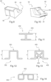
- figure 3 illustrates the classic case of a rectangular section profile.
- the reinforcement frame is referenced 152.
- an 'I' cross-section provides better resistance to bending compared to other profile sections.
- the 'I' section is symmetrical.
- the 1 section may be asymmetrical, namely one of the horizontal bars - preferably the one facing the glass panel 20 - being longer than the other: see the illustration in FIG. figure 11 in which the reinforcement frame is referenced 252.
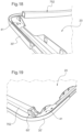
- the reinforcement frame 152 can advantageously be surrounded by a skin 154 providing a respective longitudinal cavity on either side of the vertical upright of the 'I' between its two horizontal bars: see the illustration in FIG. figure 5 .
- the skin 154 is preferably made of polymeric material. It may be a heat-shrinkable sheath, for example made of polyolefin. An example is that marketed under the reference HSR 3000 by the company 3M.
- the use of a heat-shrinkable sheath is also advantageous because it makes it possible to do without any special preparation of the surface of the reinforcing frame.
- the skin 154 may be made of a polymeric material having a natural adhesion to both the polymeric material 30 and that of the reinforcing frame.
- the skin 152 may be made of polyurethane.
- the two longitudinal cavities defined on either side of the vertical upright of the 'I' between its two horizontal bars can be previously filled with an economical plastic material, for example a polyurethane foam, in order to provide the same advantages.
- a profile section that can be produced by rollforming also called rollforming
- rollforming also called rollforming
- a profile that can be obtained by rollforming is generally less efficient than an 'I' profile in terms of mechanical resistance to bending.
- the two horizontal portions also make it possible to advantageously ensure anchoring of the reinforcement frame in the polymeric material 30.
- the profile can be supplemented by longitudinal ribs; see for example the case of the profile with a 'U' structure of the figure 10 completed by two longitudinal ribs 452 arranged diagonally and crossing as illustrated by the figure 13 where the reinforcement frame is referenced 452.
- longitudinal ribs see for example the case of the profile with a 'U' structure of the figure 10 completed by two longitudinal ribs 452 arranged diagonally and crossing as illustrated by the figure 13 where the reinforcement frame is referenced 452.
- such a profile can only be obtained by extrusion which is more expensive.
- one and/or the other of the reinforcement frames 51 and 52 are made of a composite material. This is chosen appropriately with regard to the final application. In the case of a glazed panel for a motor vehicle roof, a composite material is chosen having a glass transition temperature greater than or equal to 70°C. This characteristic makes it possible to ensure the integrity of the stiffening function of the reinforcement frames 51 and 52 after installation on a motor vehicle, with regard to the maximum temperatures to which the latter is likely to be exposed in normal use, namely approximately 60°C, but which can reach up to 120°C in tests to which the glazed panels are subjected.
- the Young's modulus of the selected composite material is significantly lower than that of steel, this difference can be compensated at least partially by defining a more complex profile shape and possibly supplemented by reinforcing ribs in order to maintain the height 'h' of the reinforcing reinforcement at a level similar to the case where the reinforcing reinforcement is made of steel.
- the reinforcing ribs can extend longitudinally and/or transversely.
- Another example further improving the mechanical resistance to bending is illustrated schematically by the Figures 15 and 16 showing respectively a front view and perspective view of a reinforcement frame referenced 552. It is based on a profile having two external side walls 557 and 558 and a bottom wall 553 all three extending over the entire length of the reinforcing frame 552. Between these three walls 553, 557 and 558 extend vertical longitudinal reinforcing ribs 554.
- transverse reinforcing ribs 556 are arranged between these three walls 553, 557 and 558 at regular distance intervals.
- the reinforcing frames are not placed in contact with the surface of the glass, but are separated from it either by a layer of polymeric material - preferably having a thickness of 1.5 to 3 mm - coming with the peripheral polymeric material 30 during its overmolding, or where appropriate by the adhesive for fixing the reinforcing frames to the glass panel 20.
- the reinforcing frames are secured to the glass panel exclusively by the peripheral polymeric material 30, it is preferable for one face of these frames forming a substantially full and continuous surface to be arranged opposite the main surface 16 of the glass panel 20, regardless of whether the reinforcing frames are made of metallic material or composite material: see references 53, 153, 253, 353, 453, 553 and 653 for the different reinforcing frames illustrated in the figures.
- This makes it possible to avoid or at least limit the appearance of harmful mechanical stresses on the glass panel 20 in the area of the reinforcing frame during injection overmolding of the peripheral polymeric material 30 due to a phenomenon of shrinkage of the polymeric material inside the reinforcing frame if it had a hollow profile open towards the glass panel 20.
- one face of the reinforcing frame forming a substantially full and continuous surface is arranged opposite the main surface 16 of the glass panel 20 because this will allow effective adhesion of the reinforcing frame to the glass panel 20.
- the two reinforcement frames may have the same or different structure, particularly with regard to the shape of their cross-sections or their dimensions.
- the reinforcing frames and the fixing frames are assembled to form a frame prior to their attachment to the glass panel 20.
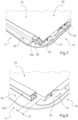
- figure 6 illustrates the example of such a frame 50 obtained by assembling two reinforcement frames 152 of the figure 5 - provided with their skin 154 - and two fixing frames 41 while the figure 7 shows a local enlargement of a corner of the frame after securing to the glass panel 20.
- the reinforcing frames 152 and the fixing frames 41 are assembled together by their longitudinal ends by means of a respective intermediate piece 60.
- the Figures 9 and 10 show two perspective views of an intermediate part 60. More particularly, each time, a longitudinal end of a reinforcing frame 152 and a longitudinal end of the corresponding fixing frame 41 are fitted into an intermediate part 60.
- the intermediate part 60 comprises a first fitting port 62 capable of receiving the longitudinal end of the reinforcing frame 152 and a second fitting port 61 capable of receiving the longitudinal end of the fixing frame 41.
- These two ports 61, 62 are preferably designed so that the fitting is done with a tightening adapted to allow manual insertion while ensuring sufficient support to be able to handle the frame without it coming apart before being secured to the glass panel 20.
- the intermediate parts 60 can be made by molding plastic material, which is particularly economical. This is preferably a plastic material reinforced with glass fibers, for example a polyamide 66.
- the intermediate part 60 can comprise stiffening ribs 64. Alternatively, it is the intermediate part 60 which is fitted into a longitudinal end of the reinforcing frame and/or into a longitudinal end of the corresponding fixing frame 41 instead of the reverse, at least if the shape of the cross section of the frames concerned allows it.
- the intermediate parts 60 After securing the frame thus formed on the glass panel 20 by adhesive and/or overmolding of the peripheral polymeric material 30, the intermediate parts 60 locally stiffen the glass panel 20 between the reinforcing frames 152 and the fixing frames 41. They thus limit the stress concentrations in the corners of the glass panel 20 and, as a result, they significantly reduce the risk of breakage of the glass panel 20 in the corner areas under the windload effect or even during tests of the glazed panel loaded in the center and suspended by its corners.
- the parts intermediate 60 are preferably designed so that, after interlocking, the separation distance 'd' between the longitudinal end of the reinforcing frame 152 and that of the fixing frame 41 is less than 30 mm, more preferably less than 20 mm, more preferably still less than 10 mm and more advantageously still less than 5 mm.
- the distance 'd' is at least 0 mm, except in a special design where the ends of the frames would overlap.
- intermediate parts 60 to assemble the reinforcement frames 152 and the fixing frames 41 can have several advantages. They make it possible to assemble the reinforcement frames and the fixing frames, whatever the shape and structure of their respective ends. They make it possible to plug the ends of the reinforcement frames in the case where they are hollow, which prevents them from filling with the peripheral polymeric material 30 during the injection molding operation. They also make it possible to assemble reinforcement frames and fixing frames made of different materials, for example of composite material for the former and of metallic material for the latter which therefore could not be assembled by welding.
- the fixing frames and the reinforcing frames are fitted directly into each other, which is possible if their ends are compatible to allow such fitting.
- the manufacture of the glass panel 10 can be carried out as follows.
- the latter and the glass panel 20 are positioned and held in a mold provided for this purpose. Then, the peripheral polymeric material 30 is overmolded on the assembly by injection into the mold.
- the mold is designed to completely overmold the reinforcing frames and the intermediate parts while the fixing frames are partially overmolded to leave accessible the parts intended for fixing the glass panel 10 to the opening translation mechanism of the motor vehicle roof by injection molding.
- the reinforcement bars and the fixing bars in the form of a frame, it is possible to simplify the positioning of the bars in the injection mould. This results in a reduction in the cycle time by positioning only one element - namely the pre-assembled frame - in the injection mould instead of four, namely each of the reinforcing frames and the fixing frames. Furthermore, the frame thus formed can be positioned and held in the injection mold exclusively by means of the non-overmolded parts of the fixing frames 41 by using, for example, systems based on positioning pins and/or magnets known per se.
- peripheral polymeric material 30 can by itself ensure the securing of the reinforcing frames and the fixing frames on the glass panel 20, as well as the intermediate parts 60.
- the frame may be secured to the glass panel 20 by adhesive - such as double-sided tape or glue - before being placed in the mold for addition of the peripheral polymeric material 30.
- the reinforcing frames 51 and 52—or their variants 152, 252, 352, 452, 552, 652—, the intermediate pieces 60, and the fixing frames 41 are completely or partially overmolded by the peripheral polymeric material 30.
- the frame formed by the reinforcing frames, the fixing frames, and, where appropriate, the intermediate connecting pieces between them, is fixed to the glass panel 20 adjacent to the peripheral polymeric material.
- the glass panel 20 is of the bilaminated type comprising an outer glass sheet 21 and an inner glass sheet 23 assembled together by a polymeric layer 22, for example polyvinyl butyral (PVB).
- the polymeric peripheral material, referenced 30' in this case polyurethane or the like - is applied to the periphery of the laminated glass 20 by injection molding or any other suitable method.
- the frame formed by the reinforcing frames, referenced 752, the fixing frames 41 and, where appropriate, the intermediate connecting pieces between them, referenced 60' is fixed to the glass panel 20 by an adhesive 70, for example a glue or a double-sided adhesive tape.
- an adhesive 70 for example a glue or a double-sided adhesive tape. It is preferable that each of the reinforcing frames 752 and the fixing frames 41, as well as each of the intermediate pieces 60', be fixed in this way by adhesive on the glass panel 20.
Landscapes
- Engineering & Computer Science (AREA)
- Mechanical Engineering (AREA)
- Body Structure For Vehicles (AREA)
- Panels For Use In Building Construction (AREA)
- Laminated Bodies (AREA)
- Window Of Vehicle (AREA)
Claims (29)
- Rahmen (50), der dazu bestimmt ist, an einer Glasscheibe (20) einer verglasten Scheibe (10; 10') für ein zu öffnendes Dach eines Kraftfahrzeugs befestigt zu werden, umfassend:- zwei Längsverstärkungsbewehrungen (51, 52; 152; 252; 352; 452; 552; 652) zum Verstärken der Glasscheibe (20) gegen Verformungen durch Biegen; und- zwei Längsfixierungsbewehrungen (41) zum Fixieren der Glasscheibe (20) in einer Außenstruktur, die zum Aufnehmen der verglasten Scheibe vorgesehen ist; wobei der Rahmen dadurch gekennzeichnet ist, dass:- die zwei Verstärkungsbewehrungen (51, 52; 151, 152) und die zwei Fixierungsbewehrungen (41) mit ihren Längsenden zum Ausbilden eines vormontierten Rahmens (50), anders ausgedrückt eines Rahmens (50), der vor dem Befestigen an der Glasscheibe (20) zum Ausbilden eines einzelnen Elements montiert wurde, paarweise zusammengefügt werden, und- mindestens eines oder jedes der Längsenden der einen oder jeder der Verstärkungsbewehrungen mit dem entsprechenden Längsende der benachbarten Fixierungsbewehrung mittels einer Einpassungsmontage zusammengefügt ist, die konfiguriert ist, um den vormontierten Rahmen (50) ohne Demontage vor der Befestigung an der Glasscheibe (20) manipulieren zu können.
- Rahmen nach Anspruch 1, wobei die Montage durch Einpassung mit Festsitz ausgeführt wird.
- Rahmen nach Anspruch 2, wobei mindestens eines oder jedes der Längsenden der einen oder jeder der Verstärkungsbewehrungen mit dem entsprechenden Längsende der benachbarten Fixierungsbewehrung ausschließlich mittels einer Einpassungsmontage mit Festsitz zusammengefügt ist.
- Rahmen nach einem der Ansprüche 1 bis 3, wobei die Einpassungsmontage eine erste Einpassung zwischen dem Längsende der Verstärkungsbewehrung und einem Zwischenverbindungsstück (60) und eine zweite Einpassung zwischen dem Längsende der Fixierungsbewehrung und dem Zwischenverbindungsstück (60) umfasst.
- Rahmen nach einem der Ansprüche 1 bis 3, wobei die Montage eine Einpassung des Längsendes der Verstärkungsbewehrung und eine Einpassung des Längsendes der Fixierungsbewehrung in einem gleichen Verbindungszwischenstück (60) umfasst.
- Rahmen nach Anspruch 4 oder 5, wobei der Abstand ("d"), der das Längsende der Verstärkungsbewehrung (152) und das Längsende der Fixierungsbewehrung (41) trennt, die in ein gleiches Zwischenverbindungsstück (60) eingepasst sind, weniger als 30 mm, vorzugsweise weniger als 20 mm, mehr bevorzugt weniger als 10 mm und mehr bevorzugt weniger als 5 mm beträgt.
- Rahmen nach einem der Ansprüche 1 bis 3, wobei die Montage eine Einpassung des Längsendes der Verstärkungsbewehrung und des Längsendes der Fixierungsbewehrung direkt ineinander umfasst.
- Rahmen nach einem der Ansprüche 1 bis 7, wobei das Längsende der Fixierungsbewehrung (41) einen abgewinkelten Teil aufweist, der dem benachbarten Längsende der Verstärkungsbewehrung (152) zugewandt ist, wobei der abgewinkelte Teil der Montage durch Einpassung dient.
- Rahmen nach einem der Ansprüche 1 bis 8, wobei eine oder jede der Verstärkungsbewehrungen aus einem metallischen Material ausgeführt ist.
- Rahmen nach einem der Ansprüche 1 bis 9, wobei mindestens eine der Verstärkungsbewehrungen (452; 552) aus Verbundmaterial ist und in Form eines Profilstücks ausgeführt ist, das durch Längsrippen (454; 554) und/oder Querrippen (556) verstärkt ist.
- Rahmen nach einem der Ansprüche 1 bis 10, wobei die Fixierungsbewehrungen aus metallischem Material ausgeführt sind.
- Verglaste Scheibe (10; 10') für ein zu öffnendes Dach eines Kraftfahrzeugs, umfassend:- eine Glasscheibe (20), die aufweist:∘ eine erste und eine zweite Hauptfläche (15, 16), und∘ einen Umfang, der für die Glasscheibe eine Vorderkante (11), eine Hinterkante (12) und eine erste und eine zweite Seitenkante (13, 14) definiert, die sich jeweils zwischen der Vorderkante (11) und der Hinterkante (12) erstrecken;- ein peripheres Polymermaterial (30), das auf dem Umfang der Glasscheibe (20) angeordnet ist; und- einen vormontierten Rahmen (50), anders ausgedrückt einen Rahmen (50), der vor der Befestigung an der Glasscheibe (20) zum Ausbilden eines einzelnen Elements montiert wird, das geeignet ist, um vor der Befestigung ohne Demontage manipuliert zu werden, nach einem der Ansprüche 1 bis 11, der an der ersten Hauptfläche (16) der Glasscheibe (20) befestigt ist;wobei:- jede der Verstärkungsbewehrungen des Rahmens (50) an der ersten Hauptfläche (16) der Glasscheibe (20) befestigt ist, die erste (51) in einem Bereich entlang der Vorderkante (11) und die zweite (52) in einem Bereich entlang der Hinterkante (12); und- jede der Fixierungsbewehrungen des Rahmens (50) an der ersten Hauptfläche (16) der Glasscheibe (20) befestigt ist, die erste (41) in einem Bereich entlang der ersten Seitenkante (13) und die zweite in einem Bereich entlang der zweiten Seitenkante (14).
- Verglaste Scheibe nach Anspruch 12, wobei die Verstärkungsbewehrungen (51, 52) und gegebenenfalls die Zwischenverbindungsstücke vollständig in dem peripheren Polymermaterial (30) eingekapselt sind und die Fixierungsbewehrungen (41, 42) teilweise mit dem peripheren Polymermaterial (30) umspritzt sind.
- Verglaste Scheibe nach Anspruch 12, wobei sich die Verstärkungsbewehrungen (752) und die Fixierungsbewehrungen (41) vollständig außerhalb des peripheren Polymermaterials (30) befinden.
- Verglaste Scheibe nach einem der Ansprüche 12 bis 14, wobei die eine oder jede der Verstärkungsbewehrungen eine Fläche (53; 153; 253; 353, 453, 553) umfasst, die gegenüber der Glasscheibe (20) positioniert ist, wobei die Fläche im Wesentlichen eine feste und durchgehende Oberfläche über die gesamte Länge der Verstärkungsbewehrung ausbildet.
- Verglaste Scheibe nach einem der Ansprüche 12 bis 15, wobei mindestens die eine der Verstärkungsbewehrungen (152) ein "I"-Profilstück ist und gegenüber der Glasscheibe (20) platziert ist, wobei eine Fläche durch den einen der zwei horizontalen Balken des "I" definiert ist.
- Verglaste Scheibe nach Anspruch 16, wobei die Verstärkungsbewehrung (152) in Form eines "I"-Profilstücks in dem peripheren Polymermaterial (30) eingekapselt ist, wobei zwei Längshohlräume (155), die hohl sind oder mit einem anderen Polymermaterial gefüllt sind, entlang der Verstärkungsbewehrung vorgesehen sind, und zwar jeweils auf beiden Seiten der vertikalen Strebe des "I"-Abschnitts zwischen den zwei horizontalen Balken des "I"-Abschnitts.
- Verglaste Scheibe nach einem der Ansprüche 12 bis 17, wobei mindestens die eine der Verstärkungsbewehrungen (352) ein "U"-Profilstück ist und gegenüber der Glasscheibe (20) platziert ist, wobei eine Fläche durch den horizontalen Balken des "U"-Abschnitts definiert ist, der die zwei vertikalen Streben des "U"-Abschnitts an einem ersten ihrer Enden miteinander verbindet, wobei die vertikalen Streben des "U" jeweils an ihren zweiten Enden durch einen horizontalen Anteil verlängert sind, der zu der Außenseite des "U" ausgerichtet ist.
- Verglaste Scheibe nach einem der Ansprüche 12 bis 18, wobei mindestens die eine der Verstärkungsbewehrungen ein Profilstück (652) ist, dessen Querschnitt aus einem ersten und einem zweiten Anteil mit jeweils im Wesentlichen quadratischem oder rechteckigem Querschnitt besteht und die voneinander beabstandet sind, während sie durch eine Verlängerung einer ihrer jeweiligen Seiten miteinander verbunden sind, wobei die Verstärkungsbewehrung gegen die Glasscheibe (20) platziert ist, wobei die Fläche (653) durch die jeweiligen Seiten definiert ist, die verlängert sind.
- Verglaste Scheibe nach einem der Ansprüche 12 bis 19, wobei die Glasscheibe (20) aus zweischichtigem Glas ist und eine erste Glasscheibe (23), die eine Dicke von 0,7 bis 3,1 mm, mehr bevorzugt von 0,7 bis 2,1 mm besitzt, und eine zweite Glasscheibe (21) umfasst, die eine Dicke von 1,4 bis 3,1 mm besitzt, wobei die erste Glasscheibe (23) vorzugsweise die erste Hauptfläche (16) der Glasscheibe (20) und die zweite Glasscheibe (21) die zweite Hauptfläche (15) der Glasscheibe (20) definiert.
- Verglaste Scheibe nach einem der Ansprüche 12 bis 20, wobei das periphere Polymermaterial (30) auf dem gesamten Umfang der Glasscheibe (20) angeordnet ist.
- Kraftfahrzeug, umfassend eine Glasscheibe (10; 10') nach einem der Ansprüche 12 bis 21, die in dem Dach des Fahrzeugs angebracht ist, in dem sie eine Öffnung ausbildet, in der sich die zwei Verstärkungsbewehrungen quer relativ zu dem Kraftfahrzeug erstrecken.
- Verfahren zum Anfertigen einer Glasscheibe (10; 10') für ein zu öffnendes Dach eines Kraftfahrzeugs nach einem der Ansprüche 12 bis 21, umfassend die Schritte:a) Bereitstellen oder Ausbilden eines vormontierten Rahmens (50), anders ausgedrückt eines Rahmens (50), der vor der Befestigung an der Glasscheibe (20) zum Ausbilden eines einzelnen Elements montiert wird, das geeignet ist, um vor der Befestigung ohne Demontage manipuliert zu werden, nach einem der Ansprüche 1 bis 11, dannb) Befestigen des vormontierten Rahmens (50) an einer Hauptfläche der Glasscheibe (20).
- Verfahren nach Anspruch 23, wobei in Schritt b) eine Befestigung zwischen der Hauptfläche der Glasscheibe und jeder Verstärkungsbewehrung und zwischen der Hauptfläche der Glasscheibe und jeder Fixierungsbewehrung ausgeführt wird.
- Verfahren nach Anspruch 24, wobei im Schritt b) eine Befestigung ferner zwischen der Hauptfläche der Glasscheibe und zwischen jedem Zwischenverbindungsstück (60) ausgeführt wird.
- Verfahren nach einem der Ansprüche 23 bis 25, wobei Schritt b) umfasst:- b1) Positionieren des vormontierten Rahmens (50) und der Glasscheibe (20) in einer Form, und- b2) Füllen der Form mit einem Polymermaterial zum Anfügen des Polymermaterials (30) auf dem Umfang der Glasscheibe (20), das die Fixierungsbewehrungen teilweise umspritzt und die Verstärkungsbewehrungen einkapselt.
- Verfahren nach Anspruch 26, wobei in dem Teilschritt b2) die Verstärkungsbewehrungen und gegebenenfalls die Zwischenverbindungsstück vollständig durch das Polymermaterial (30) eingekapselt werden.
- Verfahren nach Anspruch 26 oder 27, wobei der Teilschritt b1) das Positionieren und das Halten des vormontierten Rahmens (50) in der Form ausschließlich dank der Fixierungsbewehrungen (41) umfasst.
- Verfahren nach einem der Ansprüche 26 bis 28, wobei die Befestigung der Verstärkungsbewehrungen und der Fixierungsbewehrungen (41) sowie gegebenenfalls der Zwischenverbindungsstücke (60) auf der Glasscheibe (20) ausschließlich durch das Polymermaterial (30) gewährleistet ist.
Applications Claiming Priority (2)
| Application Number | Priority Date | Filing Date | Title |
|---|---|---|---|
| FR1759079A FR3071864B1 (fr) | 2017-09-29 | 2017-09-29 | Panneau vitre a pourtour polymerique, armatures de renfort et armatures de fixation |
| PCT/FR2018/052398 WO2019063954A1 (fr) | 2017-09-29 | 2018-09-28 | Panneau vitre a pourtour polymerique, armatures de renfort et armatures de fixation |
Publications (2)
| Publication Number | Publication Date |
|---|---|
| EP3687845A1 EP3687845A1 (de) | 2020-08-05 |
| EP3687845B1 true EP3687845B1 (de) | 2025-01-15 |
Family
ID=60627810
Family Applications (1)
| Application Number | Title | Priority Date | Filing Date |
|---|---|---|---|
| EP18808412.3A Active EP3687845B1 (de) | 2017-09-29 | 2018-09-28 | Glaspaneel mit polymerischem rand, verstärkungsrahmen und befestigungsrahmen |
Country Status (8)
| Country | Link |
|---|---|
| US (1) | US11813931B2 (de) |
| EP (1) | EP3687845B1 (de) |
| JP (1) | JP2020535062A (de) |
| CN (1) | CN109843616B (de) |
| BR (1) | BR112020005840A2 (de) |
| FR (1) | FR3071864B1 (de) |
| PL (1) | PL3687845T4 (de) |
| WO (1) | WO2019063954A1 (de) |
Families Citing this family (2)
| Publication number | Priority date | Publication date | Assignee | Title |
|---|---|---|---|---|
| US20200377013A1 (en) | 2019-05-27 | 2020-12-03 | Inalfa Roof Systems Group B.V. | Glass panel assembly for a roof of a vehicle |
| DE102024101450A1 (de) * | 2024-01-18 | 2025-07-24 | Webasto SE | Deckel für ein Fahrzeugdach und Verfahren zum Herstellen eines Deckels |
Family Cites Families (15)
| Publication number | Priority date | Publication date | Assignee | Title |
|---|---|---|---|---|
| HUP0500069A2 (hu) * | 2002-02-20 | 2005-04-28 | Saint-Gobain Glass France | Merev elemmel, adott esetben egy ráformázott műanyag részben befoglalt merev elemmel ellátott üvegezés |
| US7108317B2 (en) * | 2002-11-12 | 2006-09-19 | Honda Motor Co., Ltd. | Tilt sunroof unit |
| FR2856951B1 (fr) * | 2003-07-01 | 2006-06-23 | Saint Gobain | Vitrage comprenant un element de renfort |
| DE102004015920A1 (de) * | 2004-03-31 | 2005-10-20 | Webasto Ag Fahrzeugtechnik | Anordnung zum Verschließen einer Öffnung eines Fahrzeugs mit einem Splitterschutzelement |
| US8182025B2 (en) * | 2009-04-29 | 2012-05-22 | Inalfa Roof Systems Group B.V. | Method of producing a panel assembly |
| CN201502271U (zh) * | 2009-06-10 | 2010-06-09 | 东莞市冠辉五金有限公司 | 玻璃门窗框架 |
| JP5631944B2 (ja) * | 2012-08-22 | 2014-11-26 | 八千代工業株式会社 | サンルーフ装置 |
| FR3009806B1 (fr) * | 2013-08-01 | 2017-01-27 | Saint Gobain | Vitrage a joint profile et enjoliveur, enjoliveur et procede de fabrication du vitrage |
| FR3011203B1 (fr) * | 2013-10-01 | 2015-10-09 | Saint Gobain | Vitrage comportant une portion de joint a insert ferme et procede de fabrication dudit vitrage. |
| CN204186256U (zh) * | 2014-10-13 | 2015-03-04 | 奥星洁净设备(上海)有限公司 | 用于洁净室的窗户 |
| US10204532B2 (en) * | 2015-09-25 | 2019-02-12 | Intel Corporation | Multiple input cryptographic engine |
| JP2017132423A (ja) * | 2016-01-29 | 2017-08-03 | アイシン精機株式会社 | サンルーフ装置 |
| WO2017152980A1 (en) * | 2016-03-10 | 2017-09-14 | Inalfa Roof Systems Group B.V. | Panel and open roof construction provided therewith |
| CN106218376A (zh) * | 2016-07-22 | 2016-12-14 | 安徽省地坤汽车天窗科技有限公司 | 一种用于天窗挡风板装配的弹簧撑杆底座结构 |
| CN206124701U (zh) * | 2016-10-18 | 2017-04-26 | 上海沪帆汽车塑料件有限公司 | 一种新型结构的汽车天窗框架 |
-
2017
- 2017-09-29 FR FR1759079A patent/FR3071864B1/fr active Active
-
2018
- 2018-09-28 JP JP2020517459A patent/JP2020535062A/ja active Pending
- 2018-09-28 EP EP18808412.3A patent/EP3687845B1/de active Active
- 2018-09-28 CN CN201880003545.4A patent/CN109843616B/zh active Active
- 2018-09-28 US US16/651,837 patent/US11813931B2/en active Active
- 2018-09-28 WO PCT/FR2018/052398 patent/WO2019063954A1/fr not_active Ceased
- 2018-09-28 PL PL18808412.3T patent/PL3687845T4/pl unknown
- 2018-09-28 BR BR112020005840-8A patent/BR112020005840A2/pt not_active Application Discontinuation
Also Published As
| Publication number | Publication date |
|---|---|
| CN109843616B (zh) | 2023-09-12 |
| FR3071864B1 (fr) | 2021-06-18 |
| PL3687845T4 (pl) | 2025-05-05 |
| CN109843616A (zh) | 2019-06-04 |
| US20200254858A1 (en) | 2020-08-13 |
| EP3687845A1 (de) | 2020-08-05 |
| JP2020535062A (ja) | 2020-12-03 |
| PL3687845T3 (pl) | 2025-04-28 |
| BR112020005840A2 (pt) | 2020-09-24 |
| US11813931B2 (en) | 2023-11-14 |
| WO2019063954A1 (fr) | 2019-04-04 |
| FR3071864A1 (fr) | 2019-04-05 |
Similar Documents
| Publication | Publication Date | Title |
|---|---|---|
| EP2852502B1 (de) | Windschutzfenster mit einer scheibe, die mit einer integrierten einlage ausgerüstet ist, die eine zu einem träger des fahrzeugrahmens passende form aufweist | |
| CA2476507C (fr) | Vitrage avec un element rigide eventuellement incorpore dans une piece en plastique surmoulee | |
| CA2590679C (fr) | Vitrage complexe constitue d'au moins deux elements vitres contigus et procede de realisation de ce vitrage complexe. | |
| EP0994006B1 (de) | Verfahren zum Herstellen eines Tragwerks für die Frontseite von Kraftfahrzeugen ,und Tragwerk für die Frontseite von Kraftfahrzeugen hergestellt durch dieses Verfahren | |
| EP3083373B1 (de) | Kraftfahrzeugfassadenmodul | |
| EP3554873B1 (de) | Kraftfahrzeugstruktur mit schiebedach, dachrahmen und zugehörigem dach | |
| EP3294613B1 (de) | Strukturdach und fahrzeug mit solch einem dach | |
| EP3687845B1 (de) | Glaspaneel mit polymerischem rand, verstärkungsrahmen und befestigungsrahmen | |
| EP3106335B1 (de) | Verstärkungselement umfassende verglasung und verfahren zur dessen herstellung | |
| EP2961647B1 (de) | Heckladebodenplatte aus verbundstoff für ein kraftfahrzeug | |
| FR2814705A1 (fr) | Vitrage avec un element rigide eventuellement incorpore dans une piece en plastique surmoulee | |
| EP2459404B1 (de) | Gelenkglastafel mit kammförmigem einsatz sowie verfahren zur herstellung dieser glastafel | |
| EP2189313B1 (de) | Vorrichtung zum Verschließen einer Öffnung eines Kraftfahrzeugs, die mit einem Halterungselement ausgestattet ist, das durch Kleben befestigt ist, entsprechendes Verfahren und Fahrzeug | |
| EP3294612B1 (de) | Strukturdach und fahrzeug mit solch einem dach | |
| FR3037001A1 (fr) | Vitrage feuillete a feuilles de verre semi-trempees muni d'une portion de joint profile ayant un insert de renforcement mecanique | |
| EP1095762A1 (de) | Verfahren zur Herstellung einer Verbundplatte, insbesondere ein Fahrzeugdach oder Fussboden eines industriellen Fahrzeugs sowie nach diesem Verfahren hergestellte Platte | |
| FR3021944A1 (fr) | Partie avant de la structure d'un vehicule automobile | |
| FR3041313A1 (fr) | Montant de baie pour vehicule automobile | |
| FR2996170A1 (fr) | Vitre arriere composite panoramique. | |
| FR3106297A1 (fr) | Vitrage feuilleté pour un véhicule automobile, notamment un vitrage latéral pour une portière de véhicule | |
| EP1852338A1 (de) | Campingwagen, dessen Fahrerkabine ein Profil umfasst | |
| FR2955540A1 (fr) | Ensemble de pare-brise pour vehicule comportant un dispositif de retroviseur exterieur. |
Legal Events
| Date | Code | Title | Description |
|---|---|---|---|
| STAA | Information on the status of an ep patent application or granted ep patent |
Free format text: STATUS: UNKNOWN |
|
| STAA | Information on the status of an ep patent application or granted ep patent |
Free format text: STATUS: THE INTERNATIONAL PUBLICATION HAS BEEN MADE |
|
| PUAI | Public reference made under article 153(3) epc to a published international application that has entered the european phase |
Free format text: ORIGINAL CODE: 0009012 |
|
| STAA | Information on the status of an ep patent application or granted ep patent |
Free format text: STATUS: REQUEST FOR EXAMINATION WAS MADE |
|
| 17P | Request for examination filed |
Effective date: 20200429 |
|
| AK | Designated contracting states |
Kind code of ref document: A1 Designated state(s): AL AT BE BG CH CY CZ DE DK EE ES FI FR GB GR HR HU IE IS IT LI LT LU LV MC MK MT NL NO PL PT RO RS SE SI SK SM TR |
|
| AX | Request for extension of the european patent |
Extension state: BA ME |
|
| DAV | Request for validation of the european patent (deleted) | ||
| DAX | Request for extension of the european patent (deleted) | ||
| STAA | Information on the status of an ep patent application or granted ep patent |
Free format text: STATUS: EXAMINATION IS IN PROGRESS |
|
| 17Q | First examination report despatched |
Effective date: 20230414 |
|
| RIC1 | Information provided on ipc code assigned before grant |
Ipc: B60J 1/00 20060101ALI20240719BHEP Ipc: B60J 7/043 20060101ALI20240719BHEP Ipc: B60J 7/04 20060101ALI20240719BHEP Ipc: B60J 7/02 20060101AFI20240719BHEP |
|
| GRAP | Despatch of communication of intention to grant a patent |
Free format text: ORIGINAL CODE: EPIDOSNIGR1 |
|
| STAA | Information on the status of an ep patent application or granted ep patent |
Free format text: STATUS: GRANT OF PATENT IS INTENDED |
|
| INTG | Intention to grant announced |
Effective date: 20240904 |
|
| GRAS | Grant fee paid |
Free format text: ORIGINAL CODE: EPIDOSNIGR3 |
|
| GRAA | (expected) grant |
Free format text: ORIGINAL CODE: 0009210 |
|
| STAA | Information on the status of an ep patent application or granted ep patent |
Free format text: STATUS: THE PATENT HAS BEEN GRANTED |
|
| AK | Designated contracting states |
Kind code of ref document: B1 Designated state(s): AL AT BE BG CH CY CZ DE DK EE ES FI FR GB GR HR HU IE IS IT LI LT LU LV MC MK MT NL NO PL PT RO RS SE SI SK SM TR |
|
| REG | Reference to a national code |
Ref country code: CH Ref legal event code: EP Ref country code: GB Ref legal event code: FG4D Free format text: NOT ENGLISH |
|
| REG | Reference to a national code |
Ref country code: DE Ref legal event code: R096 Ref document number: 602018078546 Country of ref document: DE |
|
| REG | Reference to a national code |
Ref country code: IE Ref legal event code: FG4D Free format text: LANGUAGE OF EP DOCUMENT: FRENCH |
|
| RAP2 | Party data changed (patent owner data changed or rights of a patent transferred) |
Owner name: SAINT-GOBAIN SEKURIT FRANCE |
|
| REG | Reference to a national code |
Ref country code: NL Ref legal event code: MP Effective date: 20250115 |
|
| REG | Reference to a national code |
Ref country code: DE Ref legal event code: R081 Ref document number: 602018078546 Country of ref document: DE Owner name: SAINT-GOBAIN SEKURIT FRANCE, FR Free format text: FORMER OWNER: SAINT-GOBAIN GLASS FRANCE, COURBEVOIE, FR |
|
| PG25 | Lapsed in a contracting state [announced via postgrant information from national office to epo] |
Ref country code: NL Free format text: LAPSE BECAUSE OF FAILURE TO SUBMIT A TRANSLATION OF THE DESCRIPTION OR TO PAY THE FEE WITHIN THE PRESCRIBED TIME-LIMIT Effective date: 20250115 |
|
| PG25 | Lapsed in a contracting state [announced via postgrant information from national office to epo] |
Ref country code: RS Free format text: LAPSE BECAUSE OF FAILURE TO SUBMIT A TRANSLATION OF THE DESCRIPTION OR TO PAY THE FEE WITHIN THE PRESCRIBED TIME-LIMIT Effective date: 20250415 |
|
| PG25 | Lapsed in a contracting state [announced via postgrant information from national office to epo] |
Ref country code: FI Free format text: LAPSE BECAUSE OF FAILURE TO SUBMIT A TRANSLATION OF THE DESCRIPTION OR TO PAY THE FEE WITHIN THE PRESCRIBED TIME-LIMIT Effective date: 20250115 |
|
| PG25 | Lapsed in a contracting state [announced via postgrant information from national office to epo] |
Ref country code: ES Free format text: LAPSE BECAUSE OF FAILURE TO SUBMIT A TRANSLATION OF THE DESCRIPTION OR TO PAY THE FEE WITHIN THE PRESCRIBED TIME-LIMIT Effective date: 20250115 |
|
| REG | Reference to a national code |
Ref country code: LT Ref legal event code: MG9D |
|
| PG25 | Lapsed in a contracting state [announced via postgrant information from national office to epo] |
Ref country code: IS Free format text: LAPSE BECAUSE OF FAILURE TO SUBMIT A TRANSLATION OF THE DESCRIPTION OR TO PAY THE FEE WITHIN THE PRESCRIBED TIME-LIMIT Effective date: 20250515 Ref country code: NO Free format text: LAPSE BECAUSE OF FAILURE TO SUBMIT A TRANSLATION OF THE DESCRIPTION OR TO PAY THE FEE WITHIN THE PRESCRIBED TIME-LIMIT Effective date: 20250415 |
|
| REG | Reference to a national code |
Ref country code: AT Ref legal event code: MK05 Ref document number: 1759649 Country of ref document: AT Kind code of ref document: T Effective date: 20250115 |
|
| PG25 | Lapsed in a contracting state [announced via postgrant information from national office to epo] |
Ref country code: HR Free format text: LAPSE BECAUSE OF FAILURE TO SUBMIT A TRANSLATION OF THE DESCRIPTION OR TO PAY THE FEE WITHIN THE PRESCRIBED TIME-LIMIT Effective date: 20250115 |
|
| PG25 | Lapsed in a contracting state [announced via postgrant information from national office to epo] |
Ref country code: PT Free format text: LAPSE BECAUSE OF FAILURE TO SUBMIT A TRANSLATION OF THE DESCRIPTION OR TO PAY THE FEE WITHIN THE PRESCRIBED TIME-LIMIT Effective date: 20250515 Ref country code: LV Free format text: LAPSE BECAUSE OF FAILURE TO SUBMIT A TRANSLATION OF THE DESCRIPTION OR TO PAY THE FEE WITHIN THE PRESCRIBED TIME-LIMIT Effective date: 20250115 |
|
| PG25 | Lapsed in a contracting state [announced via postgrant information from national office to epo] |
Ref country code: GR Free format text: LAPSE BECAUSE OF FAILURE TO SUBMIT A TRANSLATION OF THE DESCRIPTION OR TO PAY THE FEE WITHIN THE PRESCRIBED TIME-LIMIT Effective date: 20250416 Ref country code: BG Free format text: LAPSE BECAUSE OF FAILURE TO SUBMIT A TRANSLATION OF THE DESCRIPTION OR TO PAY THE FEE WITHIN THE PRESCRIBED TIME-LIMIT Effective date: 20250115 |
|
| PG25 | Lapsed in a contracting state [announced via postgrant information from national office to epo] |
Ref country code: AT Free format text: LAPSE BECAUSE OF FAILURE TO SUBMIT A TRANSLATION OF THE DESCRIPTION OR TO PAY THE FEE WITHIN THE PRESCRIBED TIME-LIMIT Effective date: 20250115 |
|
| REG | Reference to a national code |
Ref country code: GB Ref legal event code: 732E Free format text: REGISTERED BETWEEN 20250703 AND 20250709 |
|
| PG25 | Lapsed in a contracting state [announced via postgrant information from national office to epo] |
Ref country code: SE Free format text: LAPSE BECAUSE OF FAILURE TO SUBMIT A TRANSLATION OF THE DESCRIPTION OR TO PAY THE FEE WITHIN THE PRESCRIBED TIME-LIMIT Effective date: 20250115 |
|
| PG25 | Lapsed in a contracting state [announced via postgrant information from national office to epo] |
Ref country code: SM Free format text: LAPSE BECAUSE OF FAILURE TO SUBMIT A TRANSLATION OF THE DESCRIPTION OR TO PAY THE FEE WITHIN THE PRESCRIBED TIME-LIMIT Effective date: 20250115 |
|
| PG25 | Lapsed in a contracting state [announced via postgrant information from national office to epo] |
Ref country code: DK Free format text: LAPSE BECAUSE OF FAILURE TO SUBMIT A TRANSLATION OF THE DESCRIPTION OR TO PAY THE FEE WITHIN THE PRESCRIBED TIME-LIMIT Effective date: 20250115 |
|
| PGFP | Annual fee paid to national office [announced via postgrant information from national office to epo] |
Ref country code: DE Payment date: 20250805 Year of fee payment: 8 |
|
| PGFP | Annual fee paid to national office [announced via postgrant information from national office to epo] |
Ref country code: IT Payment date: 20250825 Year of fee payment: 8 Ref country code: TR Payment date: 20250923 Year of fee payment: 8 Ref country code: PL Payment date: 20250805 Year of fee payment: 8 |
|
| PGFP | Annual fee paid to national office [announced via postgrant information from national office to epo] |
Ref country code: GB Payment date: 20250807 Year of fee payment: 8 |
|
| REG | Reference to a national code |
Ref country code: DE Ref legal event code: R097 Ref document number: 602018078546 Country of ref document: DE |
|
| PGFP | Annual fee paid to national office [announced via postgrant information from national office to epo] |
Ref country code: FR Payment date: 20250808 Year of fee payment: 8 |
|
| PG25 | Lapsed in a contracting state [announced via postgrant information from national office to epo] |
Ref country code: CZ Free format text: LAPSE BECAUSE OF FAILURE TO SUBMIT A TRANSLATION OF THE DESCRIPTION OR TO PAY THE FEE WITHIN THE PRESCRIBED TIME-LIMIT Effective date: 20250115 Ref country code: EE Free format text: LAPSE BECAUSE OF FAILURE TO SUBMIT A TRANSLATION OF THE DESCRIPTION OR TO PAY THE FEE WITHIN THE PRESCRIBED TIME-LIMIT Effective date: 20250115 |
|
| PG25 | Lapsed in a contracting state [announced via postgrant information from national office to epo] |
Ref country code: RO Free format text: LAPSE BECAUSE OF FAILURE TO SUBMIT A TRANSLATION OF THE DESCRIPTION OR TO PAY THE FEE WITHIN THE PRESCRIBED TIME-LIMIT Effective date: 20250115 |
|
| PG25 | Lapsed in a contracting state [announced via postgrant information from national office to epo] |
Ref country code: SK Free format text: LAPSE BECAUSE OF FAILURE TO SUBMIT A TRANSLATION OF THE DESCRIPTION OR TO PAY THE FEE WITHIN THE PRESCRIBED TIME-LIMIT Effective date: 20250115 |
|
| PLBE | No opposition filed within time limit |
Free format text: ORIGINAL CODE: 0009261 |
|
| STAA | Information on the status of an ep patent application or granted ep patent |
Free format text: STATUS: NO OPPOSITION FILED WITHIN TIME LIMIT |
|
| 26N | No opposition filed |
Effective date: 20251016 |