EP3687918B1 - Kappe für sportflasche - Google Patents
Kappe für sportflasche Download PDFInfo
- Publication number
- EP3687918B1 EP3687918B1 EP18857608.6A EP18857608A EP3687918B1 EP 3687918 B1 EP3687918 B1 EP 3687918B1 EP 18857608 A EP18857608 A EP 18857608A EP 3687918 B1 EP3687918 B1 EP 3687918B1
- Authority
- EP
- European Patent Office
- Prior art keywords
- hollow body
- distal end
- channel
- sleeve
- nozzle valve
- Prior art date
- Legal status (The legal status is an assumption and is not a legal conclusion. Google has not performed a legal analysis and makes no representation as to the accuracy of the status listed.)
- Active
Links
Images




Classifications
-
- B—PERFORMING OPERATIONS; TRANSPORTING
- B65—CONVEYING; PACKING; STORING; HANDLING THIN OR FILAMENTARY MATERIAL
- B65D—CONTAINERS FOR STORAGE OR TRANSPORT OF ARTICLES OR MATERIALS, e.g. BAGS, BARRELS, BOTTLES, BOXES, CANS, CARTONS, CRATES, DRUMS, JARS, TANKS, HOPPERS, FORWARDING CONTAINERS; ACCESSORIES, CLOSURES, OR FITTINGS THEREFOR; PACKAGING ELEMENTS; PACKAGES
- B65D47/00—Closures with filling and discharging, or with discharging, devices
- B65D47/04—Closures with discharging devices other than pumps
- B65D47/20—Closures with discharging devices other than pumps comprising hand-operated members for controlling discharge
- B65D47/2018—Closures with discharging devices other than pumps comprising hand-operated members for controlling discharge comprising a valve or like element which is opened or closed by deformation of the container or closure
- B65D47/2093—Closures with discharging devices other than pumps comprising hand-operated members for controlling discharge comprising a valve or like element which is opened or closed by deformation of the container or closure slide valve type
-
- B—PERFORMING OPERATIONS; TRANSPORTING
- B05—SPRAYING OR ATOMISING IN GENERAL; APPLYING FLUENT MATERIALS TO SURFACES, IN GENERAL
- B05B—SPRAYING APPARATUS; ATOMISING APPARATUS; NOZZLES
- B05B11/00—Single-unit hand-held apparatus in which flow of contents is produced by the muscular force of the operator at the moment of use
- B05B11/01—Single-unit hand-held apparatus in which flow of contents is produced by the muscular force of the operator at the moment of use characterised by the means producing the flow
- B05B11/04—Deformable containers producing the flow, e.g. squeeze bottles
- B05B11/047—Deformable containers producing the flow, e.g. squeeze bottles characterised by the outlet or venting means
-
- B—PERFORMING OPERATIONS; TRANSPORTING
- B65—CONVEYING; PACKING; STORING; HANDLING THIN OR FILAMENTARY MATERIAL
- B65D—CONTAINERS FOR STORAGE OR TRANSPORT OF ARTICLES OR MATERIALS, e.g. BAGS, BARRELS, BOTTLES, BOXES, CANS, CARTONS, CRATES, DRUMS, JARS, TANKS, HOPPERS, FORWARDING CONTAINERS; ACCESSORIES, CLOSURES, OR FITTINGS THEREFOR; PACKAGING ELEMENTS; PACKAGES
- B65D41/00—Caps, e.g. crown caps or crown seals, i.e. members having parts arranged for engagement with the external periphery of a neck or wall defining a pouring opening or discharge aperture; Protective cap-like covers for closure members, e.g. decorative covers of metal foil or paper
- B65D41/02—Caps or cap-like covers without lines of weakness, tearing strips, tags, or like opening or removal devices
- B65D41/023—Caps or cap-like covers without lines of weakness, tearing strips, tags, or like opening or removal devices with integral internal sealing means
-
- B—PERFORMING OPERATIONS; TRANSPORTING
- B65—CONVEYING; PACKING; STORING; HANDLING THIN OR FILAMENTARY MATERIAL
- B65D—CONTAINERS FOR STORAGE OR TRANSPORT OF ARTICLES OR MATERIALS, e.g. BAGS, BARRELS, BOTTLES, BOXES, CANS, CARTONS, CRATES, DRUMS, JARS, TANKS, HOPPERS, FORWARDING CONTAINERS; ACCESSORIES, CLOSURES, OR FITTINGS THEREFOR; PACKAGING ELEMENTS; PACKAGES
- B65D47/00—Closures with filling and discharging, or with discharging, devices
- B65D47/04—Closures with discharging devices other than pumps
- B65D47/20—Closures with discharging devices other than pumps comprising hand-operated members for controlling discharge
- B65D47/2018—Closures with discharging devices other than pumps comprising hand-operated members for controlling discharge comprising a valve or like element which is opened or closed by deformation of the container or closure
- B65D47/2031—Closures with discharging devices other than pumps comprising hand-operated members for controlling discharge comprising a valve or like element which is opened or closed by deformation of the container or closure the element being formed by a slit, narrow opening or constrictable spout, the size of the outlet passage being able to be varied by increasing or decreasing the pressure
-
- B—PERFORMING OPERATIONS; TRANSPORTING
- B65—CONVEYING; PACKING; STORING; HANDLING THIN OR FILAMENTARY MATERIAL
- B65D—CONTAINERS FOR STORAGE OR TRANSPORT OF ARTICLES OR MATERIALS, e.g. BAGS, BARRELS, BOTTLES, BOXES, CANS, CARTONS, CRATES, DRUMS, JARS, TANKS, HOPPERS, FORWARDING CONTAINERS; ACCESSORIES, CLOSURES, OR FITTINGS THEREFOR; PACKAGING ELEMENTS; PACKAGES
- B65D47/00—Closures with filling and discharging, or with discharging, devices
- B65D47/04—Closures with discharging devices other than pumps
- B65D47/20—Closures with discharging devices other than pumps comprising hand-operated members for controlling discharge
- B65D47/24—Closures with discharging devices other than pumps comprising hand-operated members for controlling discharge with poppet valves or lift valves, i.e. valves opening or closing a passageway by a relative motion substantially perpendicular to the plane of the seat
- B65D47/241—Closures with discharging devices other than pumps comprising hand-operated members for controlling discharge with poppet valves or lift valves, i.e. valves opening or closing a passageway by a relative motion substantially perpendicular to the plane of the seat the valve being opened or closed by actuating a cap-like element
- B65D47/242—Closures with discharging devices other than pumps comprising hand-operated members for controlling discharge with poppet valves or lift valves, i.e. valves opening or closing a passageway by a relative motion substantially perpendicular to the plane of the seat the valve being opened or closed by actuating a cap-like element moving helically
-
- B—PERFORMING OPERATIONS; TRANSPORTING
- B65—CONVEYING; PACKING; STORING; HANDLING THIN OR FILAMENTARY MATERIAL
- B65D—CONTAINERS FOR STORAGE OR TRANSPORT OF ARTICLES OR MATERIALS, e.g. BAGS, BARRELS, BOTTLES, BOXES, CANS, CARTONS, CRATES, DRUMS, JARS, TANKS, HOPPERS, FORWARDING CONTAINERS; ACCESSORIES, CLOSURES, OR FITTINGS THEREFOR; PACKAGING ELEMENTS; PACKAGES
- B65D47/00—Closures with filling and discharging, or with discharging, devices
- B65D47/04—Closures with discharging devices other than pumps
- B65D47/20—Closures with discharging devices other than pumps comprising hand-operated members for controlling discharge
- B65D47/24—Closures with discharging devices other than pumps comprising hand-operated members for controlling discharge with poppet valves or lift valves, i.e. valves opening or closing a passageway by a relative motion substantially perpendicular to the plane of the seat
- B65D47/241—Closures with discharging devices other than pumps comprising hand-operated members for controlling discharge with poppet valves or lift valves, i.e. valves opening or closing a passageway by a relative motion substantially perpendicular to the plane of the seat the valve being opened or closed by actuating a cap-like element
- B65D47/243—Closures with discharging devices other than pumps comprising hand-operated members for controlling discharge with poppet valves or lift valves, i.e. valves opening or closing a passageway by a relative motion substantially perpendicular to the plane of the seat the valve being opened or closed by actuating a cap-like element moving linearly, i.e. without rotational motion
-
- B—PERFORMING OPERATIONS; TRANSPORTING
- B65—CONVEYING; PACKING; STORING; HANDLING THIN OR FILAMENTARY MATERIAL
- B65D—CONTAINERS FOR STORAGE OR TRANSPORT OF ARTICLES OR MATERIALS, e.g. BAGS, BARRELS, BOTTLES, BOXES, CANS, CARTONS, CRATES, DRUMS, JARS, TANKS, HOPPERS, FORWARDING CONTAINERS; ACCESSORIES, CLOSURES, OR FITTINGS THEREFOR; PACKAGING ELEMENTS; PACKAGES
- B65D47/00—Closures with filling and discharging, or with discharging, devices
- B65D47/04—Closures with discharging devices other than pumps
- B65D47/20—Closures with discharging devices other than pumps comprising hand-operated members for controlling discharge
- B65D47/24—Closures with discharging devices other than pumps comprising hand-operated members for controlling discharge with poppet valves or lift valves, i.e. valves opening or closing a passageway by a relative motion substantially perpendicular to the plane of the seat
- B65D47/245—Closures with discharging devices other than pumps comprising hand-operated members for controlling discharge with poppet valves or lift valves, i.e. valves opening or closing a passageway by a relative motion substantially perpendicular to the plane of the seat the valve being opened or closed by actuating a stopper-type element
- B65D47/247—Closures with discharging devices other than pumps comprising hand-operated members for controlling discharge with poppet valves or lift valves, i.e. valves opening or closing a passageway by a relative motion substantially perpendicular to the plane of the seat the valve being opened or closed by actuating a stopper-type element moving linearly, i.e. without rotational motion
-
- B—PERFORMING OPERATIONS; TRANSPORTING
- B65—CONVEYING; PACKING; STORING; HANDLING THIN OR FILAMENTARY MATERIAL
- B65D—CONTAINERS FOR STORAGE OR TRANSPORT OF ARTICLES OR MATERIALS, e.g. BAGS, BARRELS, BOTTLES, BOXES, CANS, CARTONS, CRATES, DRUMS, JARS, TANKS, HOPPERS, FORWARDING CONTAINERS; ACCESSORIES, CLOSURES, OR FITTINGS THEREFOR; PACKAGING ELEMENTS; PACKAGES
- B65D2251/00—Details relating to container closures
- B65D2251/20—Sealing means
Definitions
- the present invention relates generally to fluid containers and, more particularly, to closure mechanisms for drinking bottles such as sports and water bottles. Specifically, the present invention relates to pop-up type valve assemblies for fluid container closure mechanisms.
- the cap body is made from a rigid or semi rigid material and the nozzle valve is made from a semi rigid semi flexible material.
- the material from which the cap body is made has a greater thermal linear expansion than the material from which the nozzle body is made.
- the nozzle valve can experience creep in size over time when subject to relatively extreme thermal conditions and hermetic or hydraulic sealing can be lost.
- hermetic and hydraulic are interchangeable. Creep can also result from mechanical events or the combination of thermal and mechanical events.
- nozzle body and cap body have different thermal linear expansion coefficients
- hot and cold events or conditions are both relevant and, depending upon how parts interface, give rise to different issues of creep.
- mechanical expansion and compression forces can give rise to creep.
- the phenomenon of creep has a greater effect on the nozzle body due to the properties of the semi rigid semi flexible material from which it is made. Expanding or compressing a nozzle valve over time can cause the shape or size of the nozzle body to expand or contract. Further still, the process of creep is accelerated at elevated temperatures and humidity levels, for example, those that occur during a typical dishwasher cleaning and drying cycle.
- elevated temperatures can drive creep to its mechanical limit altering the size or shape of the nozzle body.
- reduced temperatures experienced for example when a water bottle is placed in a freezer or when it is filled with relatively cold fluids, are less likely to result in creep because the nozzle body will stiffen and resist the effects of compression. Nonetheless, creep can still be a factor in reduced temperature conditions.
- stress can be molded into a component piece, particularly an injection molded part. Exposure to elevated temperatures can release such built-in stress. Often, such stresses cause a part to shrink. Any change in the shape or size of a part that is integral in forming a fluid seal can have a detrimental effect on the seal.
- DE 20 2013 006 816U1 discloses a cap according to the preamble of claim 1, for a bottle containing a drinkable beverage.
- the cap includes a cylindrical opening.
- a nozzle slides within a sleeve.
- a stop block is located inside the cap and includes an annular flange at the distal end. In a closed position, the distal end of the nozzle abuts the flat upper surface of the flange. A pair of limiting portions restrict movement of the sleeve.
- KR 101 007 083 B1 is directed to a container or bottle for storing and drinking liquids.
- the container includes a cap with a movable nozzle.
- a storage area is integral with the nozzle and is configured to hold liquid, powder or effervescent granules. When the nozzle is opened, the contents of the storage area fall into and mix with the liquid in the container body.
- an improved nozzle valve and an associated cap for a fluid container are described that address and resolve problems associated with thermal and mechanical creep.
- Improved methods and structures of forming a hermetic seal between the cap body and nozzle valve are described. These methods and structures address form and fit variations that occur over the life of the fluid container resulting from repeated exposure to elevated and reduced temperatures and mechanical expansion and compression events.
- a closure according to claim 1 comprising the improved nozzle valve and a cap member is intended to be used on a squeezable plastic water bottle.
- the cap dispenses the fluid contents of the bottle through a cylindrical nozzle valve that opens and closes orifices that direct the flow of the fluid as it is dispensed from the squeezable plastic water bottle.
- the nozzle valve slides upward and downward within a sleeve in the cap body to toggle between the open and closed modes. When the nozzle valve is pushed downward or inward it is in the closed mode. When the nozzle valve is in the upward or outward most position it is in the open mode.
- the semi rigid semi flexible nozzle valve and rigid or semi rigid cap body require three sets of hermetic or hydraulic seals.
- a first set of sealing surfaces facilitates the up and down travel of the nozzle valve when moving from the open and closed positions. These sealing surfaces circumferentially extend around the outer cylindrical surface of the nozzle valve and interface with the inner wall of the sleeve, similar to the function of an O-ring.
- the nozzle valve is designed with thick wall sections proximate the sealing members to reduce the effects of material creep. Compared to a thinner wall section, the shape memory of a thicker wall section is retained longer.
- the cap body and sleeve material expands more than the material of the nozzle valve due to differences in the thermal linear expansion of the materials of the nozzle valve and cap body.
- the larger thermal expansion of the cap body and sleeve reduces the mechanical force each part imparts against the other and thereby reduces the stresses that cause creep.
- the stiffening of the nozzle valve material inhibits the effect of creep.
- the second and third set of sealing surfaces are at the bottom inner diameter and outer diameter of the movable nozzle valve, respectively, and are required to form a hermetic or hydraulic seal when in the closed mode.
- the inner diameter seal is formed by the distal end of the nozzle valve stretching over a larger diameter cylindrical plug located at the distal end of the sleeve of the cap body.
- the distal end of the nozzle valve utilizes a thin wall construction because it must not cause frictional forces that hinder the upward and downward travel of the nozzle valve when the user is toggling between the open and closed positions of the nozzle valve. Because it is thinner, it is more susceptible to the effects of creep.
- the inner surface of the distal end of the nozzle valve interfaces with the outer surface of the plug at the distal end of the sleeve and the larger diameter outer surface of the plug imparts a mechanical expansion force on the inner diameter surface of the distal end of the nozzle valve.
- This mechanical stress will cause the nozzle valve material to creep. Exposure to elevated temperature events over time will accelerate the creep. The result of the creep is that the distal end of the nozzle valve will assume a larger diameter. The larger diameter may or may not form a seal when the nozzle valve is in a closed position. However, the nozzle valve will leak when subjected to colder temperatures that cause the cap body to shrink more than the nozzle valve.
- a third set of sealing surfaces are formed between the bottom outer diameter of the nozzle valve and a mating surface of the cap body. More particularly, in one embodiment, a cylindrical channel is formed in the cap body that defines an inner surface and an outer surface. When the valve body is in the closed position, the bottom or distal end of the valve body is seated in the channel with the inner diameter of the valve body mating with the inner surface of the channel as described above in connection with the second set of sealing surfaces, and the outer diameter of the valve body mating with the outer surface of the channel (a third set of sealing surfaces).
- the outer surface of the channel and the outer surface of the valve body are configured to force the outer surface of the valve body radially inwardly.
- the interface between the outer surface of the channel and the outer surface of the distal end of the nozzle valve counteract the creep and create at least one and preferably two hermetic seals.
- the second surface of the distal end of the sleeve is angled relative to the longitudinal axis of the sleeve.
- the outer surface of the distal end of the nozzle valve is angled relative to the longitudinal axis of the sleeve.
- the cap body further comprises an anti-spill member positioned in the hollow body of the valve.
- the cylindrical sleeve is made from polyethylene and the nozzle valve is made from at least one of urethane, silicone, natural rubber, synthetic rubber and polyimide.
- the coefficient of thermal linear expansion of the cylindrical sleeve is greater than the coefficient of thermal linear expansion of the nozzle valve.
- the cap body further comprises a radially outwardly extending lip positioned at the distal end of the sleeve, the lip comprising the first and second surfaces of the distal end of the sleeve and forming a channel, and wherein the distal end of the valve body nests in the channel in the closed position.
- This same nozzle valve may optionally contain structure that acts as a self-sealing valve within the said cylindrical nozzle.
- the self-sealing valve acts as a spill deterrent when the cylindrical nozzle is in the open mode.
- Figure 1 discloses one embodiment of a cap structure 2 that is intended to be used on a squeezable plastic water bottle 4.
- the cap structure minimally comprises two parts: a body 6 and a nozzle valve 8.
- the bottle 4 may comprise a variety of shapes. According to aspects of the present disclosure, the bottle 4 is generally cylindrical in shape having a longitudinal axis that extends through the nozzle 8. Other bottle shapes and configurations are within the scope of the present disclosure.
- the cap body 6 is generally cylindrical in nature and sized to form a hermetic seal across the open neck 12 of bottle 4.
- a sealing surface 14 is formed between the cap 6 and bottle 4 when the screw threads 16 engage mating features 18 of the bottle neck 20.
- the cap 2 dispenses the fluid contents of the bottle through the proximal end 22 of a cylindrical nozzle valve 8 that acts to open and close orifices 24 ( Fig. 2 and Fig. 3 ) that direct the flow of the fluid as it is dispensed from the squeezable plastic water bottle 4.
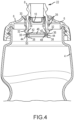
- the cylindrical nozzle valve 8 is toggled from the open position illustrated in Fig. 2 and closed position illustrated in Figure 4 by the operator. If the nozzle valve 8 is pushed downward or inward it closes or if it is pulled upward or outward it opens. In this configuration, the motion of the nozzle valve 8 is along the longitudinal axis of the bottle 4.
- the cap body 6 is rigid or semi rigid in nature and can be made from any number of rigid or semi rigid materials, for example, impact resistant thermoplastic or impact resistant polyethylene such as high-density polyethylene (“HDPE”) and low-density polyethylene (“LDPE”).
- the cylindrical nozzle valve 8 is made from a semi flexible semi rigid material, for example, thermoplastic elastomers (TPE) such as urethane, silicone, natural rubber, synthetic rubber or polyimide, because the soft properties of these materials are good for accommodating surface imperfections and a press fit required in forming effective hermetic or hydraulic seals.
- TPE thermoplastic elastomers
- the cap body 6 Due to the material from which it is made, the cap body 6 has a coefficient of thermal linear expansion that is larger than the coefficient of thermal linear expansion of the nozzle valve 8. Conversely, due to the material from which it is made, the nozzle valve 8 has a coefficient of thermal linear expansion that is less than the coefficient of thermal expansion of the cap body 6.
- the semi flexible semi rigid materials of the valve body 8 accommodate a user that might tug on the nozzle valve 8 with his teeth to pull it upward into the open mode while taking a drink.
- the nozzle valve 8 is configured with one or more sealing members 26 formed around the exterior surface, for example, in an O-ring geometry ( Figs. 2 and 4 ), that form a hermetic seal by pressing against the inner surface 28 of a sleeve 30 formed in the cap body 6 in both the open and closed modes of the plastic cap 2.
- the sleeve 30 includes one or more orifices 24 that extend through the wall of the sleeve and permit fluid to flow through the sleeve and out the proximal end of the nozzle valve 8 when the nozzle valve 8 is not in the closed position.
- the bottom or distal end of the nozzle valve 8 defines an inner surface 34 and an outer surface 36.
- the thickness of the nozzle valve 8 between the surfaces 34 and 36 at the distal end of the nozzle valve 8 is relatively thin, and preferably thinner than the thickness of the valve 8 proximate the sealing members 26.
- At least one ear 32 projects radially outwardly from the valve body 8 and is disposed within at least one orifice 24.
- the nozzle valve comprises at least one ear 32 positioned in two different orifices 24.
- a plug 46 closes the distal end of the cylindrical sleeve 30 and a radially outwardly projecting lip 38 is formed radially outwardly from the plug 46 at the bottom or distal end of the cylindrical sleeve 30.
- a channel 40 is formed in the lip 38 and defines an inner surface 42 and an outer surface 44.
- the distal end of the nozzle valve 8 forms a hermetic seal at the bottom inner diameter surface 34 and bottom outer diameter surface 36 by pressing against surfaces 42 and 44 ( Fig. 7 ) of the cap body 6, respectively, as shown in Fig. 4 .
- surface 42 is cylindrical, polished and molded without draft. The reason it is preferable that surface has no draft is to maximize the length of contact between surfaces 34 and 42 while the nozzle valve is sliding from the open position to the closed position.
- the bottom surface 48 of the nozzle valve 8 may engage the bottom surface 50 of the channel, as shown in Fig. 4 .
- the bottom 50 of the channel may be spaced from the bottom 48 of the valve body 8 with the surfaces 42 and 44 could be sized differently, having a longer dimension parallel with the longitudinal axis of the bottle.
- the diameter of surface 42 is sized larger than the diameter of surface 34 ( Fig. 6 ) of the nozzle valve 8 to create a press fit between the flexible nozzle valve and the more rigid cap body.
- the diameter of surface 42 is 0.254 mm (0.010 inches) larger than the diameter of surface 34.
- the wall thickness of the nozzle valve between surfaces 34 and 36 is small or thin enough to allow the users to stretch surface 34 across surface 42 without requiring excessive force to be supplied by the user when toggling the nozzle valve between the open mode to the closed mode.
- surface 36 of the nozzle valve presses against surface 44 of the cap body to form another hermetic sealing surface and to wedge or force the inner surface 34 of the nozzle valve 8 more tightly against surface 42 of the cap body.
- the distal end of the nozzle valve 8 and the channel 40 are substantially cylindrical and the outer surface 44 of the channel 40 is configured to press the outer surface 36 of the distal end of the nozzle valve 8 radially inwardly such that the inner surface 34 of the distal end of the nozzle valve 8 forms a sealed engagement with the inner surface 42 of the channel 40.
- the outer surface 44 of the of the channel 40 forms a sealed engagement with the outer surface 36 of the distal end of the nozzle valve 8.
- the outer surface 36 of the distal end of the nozzle valve 8 may be configured to interface with the outer surface 44 of the channel to achieve the same radially inwardly directed force.
- the material creep of the semi flexible nozzle valve 8 is exaggerated by the fact that the mating parts, the nozzle valve 8 and the sleeve 30, have two different coefficients of thermal linear expansion.
- the cap body 6 is made from a polyethylene resin with a coefficient of linear thermal expansion of 216 ⁇ m / m °C (120 micro inch / inch Fahrenheit) and the nozzle valve 8 is made from a thermoplastic urethane with a coefficient of linear thermal expansion of 153 ⁇ m / m °C (85 micro inch / inch Fahrenheit).
- This difference can result in a relative difference in linear expansion of 0.0508 mm (.002 inches) across the geometry of features 34 and 42 assuming a dishwasher temperature of 65.6 °C (150 F) and a diameter of 19.05 mm (.750 inches), which is a preferred structure of surface 42.
- surface 42 which stretches surface 34 when the nozzle valve 8 is in the closed position, expands 0.0508 mm (.002 inches) more than the semi flexible semi rigid nozzle valve 8 would grow when subjected to the same elevated temperature of 65.6 °C (150° F).
- the nozzle valves 8 have a greater tendency to lose their elastic memory and thereby dimensionally creep to a larger or expanded shape or diameter.
- the mating parts When the bottle cap 2 cools down to room temperature from the elevated temperatures of the dishwasher, the mating parts will not be sized the same as before the extreme temperature event.
- the mating surface 34 and 42 will either be sized identically to one another such there is no longer a pressing between them or there will be a gap between the sealing surfaces 34 and 42 depending on the number of dishwashing cycles and the age of the parts.
- surface 42 with the larger coefficient of linear thermal expansion will shrink more than the nozzle valve sealing surface 34 which will create a gap between sealing surfaces 34 and 42. The net result is that the interface at surfaces 34 and 42 will leak absent the presence and influence of sealing surfaces 36 and 44.
- sealing surface 44 ( Figs. 2 and 4 ) of the cap body is angled to wedge or force the inside surface 34 of the nozzle valve against surface 42 of the cap body by pressing on the circumference 36 of the nozzle valve 8.
- the radially inwardly directed force can be enhanced or varied by the altering the shape of surface 44 and/or the complementary surface 36.
- the surfaces 36 and 44 are angled or slanted to press or force the distal end of the valve 8 radially inwardly.
- one surface (36 or 44) could be aligned generally parallel with the longitudinal axis of the nozzle valve 8, and the other surface could be angled relative to the longitudinal axis of the nozzle valve 8.
- the surface generally parallel to the longitudinal axis would be substantially cylindrical while the surface disposed at an angle relative to the longitudinal axis would be frusto-conical in shape.
- the tendency of the diameter of the distal end of the nozzle valve 8 to increase to the diameter size of the inner surface 42 of the channel 40 is counteracted by the presence of the interface between the outer surface 44 of the channel 40 and the outer surface 36 of the nozzle valve 8 which acts to prevent expansion of the diameter of the distal end of the nozzle valve.
- the nozzle valve is in the open position during multiple thermal events, even if the distal end did tend to enlarge over time, the presence and operation of the outer surface 44 of the channel 40 acting on the outer surface 36 of the distal end of the nozzle valve will compel the inner surface 34 of the distal end of the nozzle valve into contact with the inner surface 42 of the channel 40.
- the cap body surface 28 will expand to a larger diameter than the nozzle valve 8 due to the larger coefficient of linear thermal expansion of the cap body material. More specifically, the diameter of surface 28, which preferably is 0.02413 m (.950 inches), will be 0.0635 mm (.0025 inches) larger than the O-ring geometry of the first sealing features 26 at the elevated temperatures of a dishwasher. The net effect is that the sealing features 26 will be less likely to be affected by creep because there is less compression of the sealing surfaces 26 of the nozzle valve against the surface 28 of the cap body at the elevated temperatures that are likely to cause creep.
- the valve 8 may optionally include a self-sealing valve 10 as shown in Fig. 2 that acts as a spill deterrent when the cap is in the open mode ( Fig. 3 ) and the bottle is tipped over.
- a self-sealing valve 10 as shown in Fig. 2 that acts as a spill deterrent when the cap is in the open mode ( Fig. 3 ) and the bottle is tipped over.
- Figure 8 shows an example of a section view of a generally accepted structure of a plastic cap without a self-sealing valve. A cap body B and a movable nozzle N are illustrated. Exemplary embodiments of a movable nozzle without a self-sealing valve are disclosed in U.S. Patents 7,753,234 and 8,646,663 .
- This self-sealing valve 10 is housed within the nozzle valve 8 and requires a different method of forming a hermetic seal between the nozzle valve 8 and cap body 6 that is generally understood in the market place for plastic caps that do not incorporate a self-sealing valve 10.
- valve body 8 an alternative embodiment of the valve body 8 is illustrated in Fig. 9 .
- the exterior of the valve body 8 optionally includes a stabilizing feature 52. This feature provides stability to the movement of the nozzle valve 8, particularly preventing or reducing rocking that would cause axial misalignment of the nozzle valve relative to the sleeve due to heavy side loads.
Landscapes
- Engineering & Computer Science (AREA)
- Mechanical Engineering (AREA)
- Closures For Containers (AREA)
Claims (11)
- Verschluss für einen Behälter, der zum Aufnehmen eines auszugebenden Fluids ausgebildet ist und eine Öffnung aufweist, umfassend:(a) ein Kappenelement (2), das an dem Behälter (4) montiert werden kann und die Öffnung umschließt, wobei das Kappenelement eine zylinderwandige Hülse (30), die eine äußere Öffnung in dem Kappenelement (2) bildet, und mindestens eine in der Hülse (30) ausgebildete Öffnung (24) aufweist;(b) ein bewegliches Düsenventil (8), das einen im Wesentlichen zylindrischen Hohlkörper (8) aufweist und für eine Längsbewegung innerhalb der zylinderwandigen Hülse (30) zwischen einer offenen Position, um den Fluss eines Fluids durch den Hohlkörper (8) aus dem Behälter (4) zu gestatten, und einer geschlossenen Position, um den Fluss eines Fluids durch den Hohlkörper (8) zu verhindern, angeordnet ist, wobei der Hohlkörper (8) mindestens ein Dichtungselement (26) aufweist, das von einer Außenfläche radial nach außen vorsteht und an der zylinderwandigen Hülse (30) anliegt, wobei der Hohlkörper (8) eine Nase (32) aufweist, die radial nach außen vorsteht und in der mindestens einen Öffnung (24) aufgenommen ist, um ein Endanschlagelement zum Begrenzen der Bewegung des Hohlkörpers (8) innerhalb der Hülse (30) zwischen der offenen und der geschlossenen Position zu definieren; wobeidas Kappenelement (2) eine sich radial nach außen erstreckende Lippe (38) aufweist, die am distalen Ende der Hülse (30) ausgebildet ist, und wobei die mindestens eine Öffnung (24) in der Hülse (30) zwischen der äußeren Öffnung und der Lippe (38) ausgebildet ist, wobei der Hohlkörper (8) ein distales Ende mit einer Innen- und einer Außenfläche aufweist;dadurch gekennzeichnet, dass die zylinderwandige Hülse (30) die äußere Öffnung in dem Kappenelement (2) am proximalen Ende der Hülse (30) bildetund dass in der Lippe (38) ein Kanal (40) ausgebildet ist, wobei der Kanal (40) eine Innenfläche (42) und eine Außenfläche (44) definiert,wobei das distale Ende des Hohlkörpers (8) in dem Kanal (40) angeordnet ist, wenn sich das Ventil in der geschlossenen Position befindet, und die Innenfläche des distalen Endes des Hohlkörpers (8) an der Innenfläche des Kanals (40) anliegt und die Außenfläche des distalen Endes des Hohlkörpers (8) an der Außenfläche des Kanals (40) anliegt, um eine Dichtung zwischen dem distalen Ende des Hohlkörpers (8) und dem Kanal (40) zu bilden.
- Verschluss nach Anspruch 1, des Weiteren umfassend ein in dem Hohlkörper des Ventils (8) angeordnetes Auslaufverhinderungselement (10).
- Verschluss nach Anspruch 1 oder 2, dadurch gekennzeichnet, dass die zylinderwandige Hülse (30) aus Polyethylen hergestellt ist und der Hohlkörper (8) aus mindestens einem der Materialien Urethan, Silikon, Naturkautschuk, Synthesekautschuk und Polyimid hergestellt ist.
- Verschluss nach einem der Ansprüche 1 bis 3, dadurch gekennzeichnet, dass der thermische Längenausdehnungskoeffizient der zylinderwandigen Hülse (30) größer ist als der thermische Längenausdehnungskoeffizient des Hohlkörpers (8).
- Verschluss nach Anspruch 4, dadurch gekennzeichnet, dass der Unterschied zwischen den thermischen Längenausdehnungskoeffizienten für die zylinderwandige Hülse (30) und für das Düsenventil (8) ungefähr 0,0508 mm (0,002 Inch) bei 65,6 °C (einhundertfünfzig Grad Fahrenheit) beträgt.
- Verschluss nach einem der Ansprüche 1 bis 5, dadurch gekennzeichnet, dass der Hohlkörper (8) eine Dicke aufweist und die Dicke des Hohlkörpers (8) in der Nähe des mindestens einen Dichtelements (26) größer ist als am distalen Ende des Ventils.
- Verschluss nach einem der Ansprüche 1 bis 6, dadurch gekennzeichnet, dass die Außenfläche des Kanals (40) dafür ausgebildet ist, die Außenfläche des distalen Endes des Hohlkörpers (8) radial nach innen zu drängen, wenn die Außenfläche des Kanals (40) an der Außenfläche des distalen Endes des Hohlkörpers (8) anliegt.
- Verschluss nach einem der Ansprüche 1 bis 7, wobei die zylinderwandige Hülse (30) ein geschlossenes distales Ende aufweist und die Innenfläche (42) des Kanals (40) eine erste Zylinderfläche mit einem ersten Durchmesser ist und die Außenfläche (44) des Kanals eine zweite Fläche ist, die radial auswärts der ersten Fläche positioniert ist; und wobei, wenn der Hohlkörper (8) in der geschlossenen Position ist, das distale Ende des Hohlkörpers (8) zwischen der ersten Zylinderfläche und der zweiten Fläche des Kanals (40) angeordnet ist, die Innenfläche des distalen Endes des Hohlkörpers (8) eine Fluiddichtung mit der ersten Fläche des Kanals (40) bildet, die Außenfläche des distalen Endes des Hohlkörpers (8) eine Fluiddichtung mit der zweiten Fläche des Kanals (40) bildet, und die Außenfläche des distalen Endes des Hohlkörpers (8) und die zweite Fläche des Kanals (40) dafür ausgebildet sind, eine radial nach innen gerichtete Kraft auf das distale Ende des Hohlkörpers (8) auszuüben, sodass die Innenfläche des distalen Endes des Hohlkörpers (8) an der ersten Zylinderfläche des distalen Endes der Hülse (30) anliegt.
- Verschluss nach Anspruch 8, dadurch gekennzeichnet, dass die zweite Fläche des distalen Endes der Hülse (30) relativ zur Längsachse der Hülse (30) gewinkelt ist.
- Verschluss nach Anspruch 9, dadurch gekennzeichnet, dass die Außenfläche des distalen Endes des Hohlkörpers (8) relativ zur Längsachse der Hülse (30) gewinkelt ist.
- Fluidbehälter (2), umfassend einen Verschluss nach einem der Ansprüche 1 bis 10 in Kombination mit einem Behälterkörper (4), der eine Öffnung aufweist, die zum Aufnehmen der Kappe (2) ausgebildet ist.
Applications Claiming Priority (3)
| Application Number | Priority Date | Filing Date | Title |
|---|---|---|---|
| US201662398728P | 2016-09-23 | 2016-09-23 | |
| US15/715,019 US10322855B2 (en) | 2016-09-23 | 2017-09-25 | Sports bottle cap |
| PCT/US2018/052664 WO2019060895A1 (en) | 2016-09-23 | 2018-09-25 | BOTTLE CAP FOR SPORT |
Publications (3)
| Publication Number | Publication Date |
|---|---|
| EP3687918A1 EP3687918A1 (de) | 2020-08-05 |
| EP3687918A4 EP3687918A4 (de) | 2021-07-21 |
| EP3687918B1 true EP3687918B1 (de) | 2024-10-30 |
Family
ID=61688258
Family Applications (1)
| Application Number | Title | Priority Date | Filing Date |
|---|---|---|---|
| EP18857608.6A Active EP3687918B1 (de) | 2016-09-23 | 2018-09-25 | Kappe für sportflasche |
Country Status (3)
| Country | Link |
|---|---|
| US (2) | US10322855B2 (de) |
| EP (1) | EP3687918B1 (de) |
| WO (1) | WO2019060895A1 (de) |
Families Citing this family (15)
| Publication number | Priority date | Publication date | Assignee | Title |
|---|---|---|---|---|
| EP1546021B1 (de) * | 2002-08-13 | 2010-10-20 | Medical Instill Technologies, Inc. | Behälter und ventilanordnung zum lagern und abgeben von substanzen und verwandtes verfahren |
| US10322855B2 (en) * | 2016-09-23 | 2019-06-18 | Hydrapak Llc | Sports bottle cap |
| DE102016222682B3 (de) * | 2016-11-17 | 2017-10-05 | Aptar Radolfzell Gmbh | Austragkopf für einen Flüssigkeitsspender und Flüssigkeitsspender mit einem solchen Austragkopf |
| US10358270B1 (en) | 2018-05-31 | 2019-07-23 | Camelbak Products, Llc | Closure assemblies and drink containers including the same |
| USD864658S1 (en) | 2018-05-31 | 2019-10-29 | Camelbak Products, Llc | Beverage container closure |
| US11172772B2 (en) | 2018-08-31 | 2021-11-16 | Hydrapak Llc | Straw cap with an open and closed valve mechanism |
| USD889974S1 (en) * | 2019-02-13 | 2020-07-14 | Pepsico, Inc. | Bottle |
| USD907955S1 (en) * | 2019-09-18 | 2021-01-19 | Hydrapak Llc | Bottle cap |
| USD903408S1 (en) * | 2019-09-18 | 2020-12-01 | Hydrapak Llc | Bottle cap |
| USD950380S1 (en) | 2020-04-17 | 2022-05-03 | Travents, LLC | Clampable cover for water or sports bottle |
| WO2022072744A1 (en) * | 2020-09-30 | 2022-04-07 | Enlightened Product Solutions, LLC | Renewably-sourced biodegradable polyolefin packaging, utensils, and containers |
| USD953115S1 (en) * | 2021-03-05 | 2022-05-31 | Shanghai Good Dog Technology Co., Lld. | Water bottle |
| USD996900S1 (en) | 2021-05-14 | 2023-08-29 | Hydrapak Llc | Beverage container |
| USD999630S1 (en) * | 2022-01-24 | 2023-09-26 | Helen Of Troy Limited | Lid for a bottle |
| USD1121440S1 (en) * | 2024-06-05 | 2026-04-07 | Hydrapak Llc | Beverage container cap |
Family Cites Families (30)
| Publication number | Priority date | Publication date | Assignee | Title |
|---|---|---|---|---|
| US2969168A (en) * | 1958-04-21 | 1961-01-24 | Us Cap & Closure Inc | Dispensing closures |
| US3240399A (en) | 1963-08-14 | 1966-03-15 | Ned W Frandeen | Dispensing receptacle |
| US3201013A (en) | 1963-12-11 | 1965-08-17 | Product Design & Engineering I | Dispensing and closure cap for containers |
| US3294294A (en) * | 1964-12-08 | 1966-12-27 | Colgate Palmolive Co | Dispensing closure with slide |
| US3511420A (en) * | 1967-06-29 | 1970-05-12 | Milton Kessler | Push-pull dispensing cap with double seal |
| US4428508A (en) | 1981-07-06 | 1984-01-31 | Gardikas Paul T | Athletes water bottle |
| US4457454A (en) | 1981-10-26 | 1984-07-03 | Philip Meshberg | Two-compartment dispenser |
| US4629098A (en) | 1984-10-15 | 1986-12-16 | Eger Douglas R | Portable liquid dispenser |
| US4976364A (en) | 1990-01-30 | 1990-12-11 | Solomon Stanley B | Cap and straw assembly for a water bottle |
| US5022562A (en) | 1989-07-11 | 1991-06-11 | Lurkis Jeffry L | Combination protective cap and valve opener |
| US5094363A (en) | 1990-07-16 | 1992-03-10 | Monahan Timothy M | Insulated water bottle for a bicycle |
| US5145094A (en) | 1990-08-20 | 1992-09-08 | Edward M. Bennett | Dispensing closure for squeeze bottle |
| US5494198A (en) | 1991-01-24 | 1996-02-27 | Heiberger; Robert A. | Insulated container |
| US5669427A (en) | 1994-03-23 | 1997-09-23 | Hasper; Pat K. | Valve assembly for use with a bottle or a container |
| US5775528A (en) | 1995-08-21 | 1998-07-07 | Superseal Corporation | Snap-on/screw-off cap and neck configuration |
| US5651471A (en) | 1995-11-03 | 1997-07-29 | Green; Dennis E. | Removable top for drinking bottles |
| US5607073A (en) | 1996-02-20 | 1997-03-04 | Forrer; Scott M. | Valve |
| NL1002577C2 (nl) | 1996-03-12 | 1997-09-15 | On Top Products B V | Verwisselbare afsluit- en schenkdop. |
| NL1003164C2 (nl) | 1996-05-20 | 1997-11-21 | On Top Products B V | Afsluitbare schenkdop. |
| US5788125A (en) | 1996-06-10 | 1998-08-04 | Steiner; Edward H. | Sip and spray fluid container assembly |
| US5839623A (en) | 1996-07-29 | 1998-11-24 | Pure Vision International, L.L.P. | Reusable pressure spray container |
| BR9701142A (pt) | 1997-02-28 | 1998-12-15 | Unilever Nv | Sistema regulador de fluxo para um recipiente contendo fluídos preferencialmente viscosos |
| US5850908A (en) | 1997-10-29 | 1998-12-22 | Jasek; Sidney Joseph | Pressure sensitive cap closure and valve |
| US6095382A (en) * | 1998-09-21 | 2000-08-01 | Aptargroup, Inc. | Container and closure with dispensing valve and separate releasable internal shipping seal |
| US7753234B1 (en) * | 1999-01-26 | 2010-07-13 | Product Architects, Inc. | Fluid container closure mechanism with detachable valve assembly |
| US6029855A (en) | 1999-02-16 | 2000-02-29 | Adams; Douglas W. | Cap and figurine device |
| KR101007083B1 (ko) | 2006-10-18 | 2011-01-10 | 이선희 | 이종물질 수용장치 |
| DE102012002935A1 (de) * | 2012-02-16 | 2013-08-22 | Mapa Gmbh | Push-Pull-Verschluss für einen Trinkbehälter |
| TWM447366U (zh) | 2012-09-21 | 2013-02-21 | Co Union Industry Co Ltd | 水壺蓋 |
| US10322855B2 (en) * | 2016-09-23 | 2019-06-18 | Hydrapak Llc | Sports bottle cap |
-
2017
- 2017-09-25 US US15/715,019 patent/US10322855B2/en active Active
-
2018
- 2018-09-25 WO PCT/US2018/052664 patent/WO2019060895A1/en not_active Ceased
- 2018-09-25 EP EP18857608.6A patent/EP3687918B1/de active Active
-
2019
- 2019-06-18 US US16/445,045 patent/US20200002064A1/en not_active Abandoned
Also Published As
| Publication number | Publication date |
|---|---|
| EP3687918A1 (de) | 2020-08-05 |
| US20180086517A1 (en) | 2018-03-29 |
| US10322855B2 (en) | 2019-06-18 |
| EP3687918A4 (de) | 2021-07-21 |
| WO2019060895A1 (en) | 2019-03-28 |
| US20200002064A1 (en) | 2020-01-02 |
Similar Documents
| Publication | Publication Date | Title |
|---|---|---|
| EP3687918B1 (de) | Kappe für sportflasche | |
| US6662977B2 (en) | Modular valve assembly and system with airtight, leakproof and shockproof closure for engagement in the neck of a container | |
| EP2076450B1 (de) | Flasche zur aufnahme von fluiden, insbesondere für pharmazeutische produkte oder dergleichen | |
| CN101573273B (zh) | 用于饮料容器的分配盖 | |
| US8210375B2 (en) | Pour cap for fluid containers having gasket configured to form fluid flow passage and low pressure seals in open position and high pressure seal in closed position | |
| US6273305B1 (en) | Valves for packaging containers | |
| US10213062B2 (en) | Pump for dispensing fluids | |
| US20080041890A1 (en) | Valve mechanism for tube-type fluid container | |
| US8584877B2 (en) | Pour cap for fluid containers having open or closed position communication structure with sound and visual features | |
| US20080264979A1 (en) | Dispensing valve and a container for holding fluid provided with such a dispensing valve | |
| US10000316B2 (en) | One-way valve for a compressible container and container with such a valve | |
| CN113453991A (zh) | 容器和用于容器的密封件 | |
| JP6903905B2 (ja) | 液ダレ防止キャップおよびその製造方法 | |
| KR100575250B1 (ko) | 튜브형 유체용기용 밸브 메커니즘 | |
| CA2761281A1 (en) | Pour cap for fluid containers | |
| US20110100950A1 (en) | Stopper for a container neck and a molding machine for molding a plastics material for the purpose of fabricating such a stopper | |
| JP4921477B2 (ja) | 液体容器用の分配用栓 | |
| JP6250441B2 (ja) | バルブユニットおよびそれを備えた容器 | |
| KR20240047996A (ko) | 용기용 마개 및 용기와 마개 | |
| US8083108B2 (en) | Dispensing caps for liquid containers | |
| JP6960851B2 (ja) | 吐出容器 | |
| NZ518471A (en) | Snap-action closure with an elastic seal | |
| WO2013175216A1 (en) | A dispensing valve | |
| JP2018020847A (ja) | バルブユニットおよびそれを備えた容器 | |
| MXPA00001816A (en) | Valves for packaging containers |
Legal Events
| Date | Code | Title | Description |
|---|---|---|---|
| STAA | Information on the status of an ep patent application or granted ep patent |
Free format text: STATUS: THE INTERNATIONAL PUBLICATION HAS BEEN MADE |
|
| PUAI | Public reference made under article 153(3) epc to a published international application that has entered the european phase |
Free format text: ORIGINAL CODE: 0009012 |
|
| STAA | Information on the status of an ep patent application or granted ep patent |
Free format text: STATUS: REQUEST FOR EXAMINATION WAS MADE |
|
| 17P | Request for examination filed |
Effective date: 20200430 |
|
| AK | Designated contracting states |
Kind code of ref document: A1 Designated state(s): AL AT BE BG CH CY CZ DE DK EE ES FI FR GB GR HR HU IE IS IT LI LT LU LV MC MK MT NL NO PL PT RO RS SE SI SK SM TR |
|
| AX | Request for extension of the european patent |
Extension state: BA ME |
|
| DAV | Request for validation of the european patent (deleted) | ||
| DAX | Request for extension of the european patent (deleted) | ||
| A4 | Supplementary search report drawn up and despatched |
Effective date: 20210618 |
|
| RIC1 | Information provided on ipc code assigned before grant |
Ipc: B65D 47/20 20060101AFI20210614BHEP Ipc: B05B 11/04 20060101ALI20210614BHEP Ipc: B65D 41/02 20060101ALI20210614BHEP Ipc: B65D 47/24 20060101ALI20210614BHEP |
|
| GRAP | Despatch of communication of intention to grant a patent |
Free format text: ORIGINAL CODE: EPIDOSNIGR1 |
|
| STAA | Information on the status of an ep patent application or granted ep patent |
Free format text: STATUS: GRANT OF PATENT IS INTENDED |
|
| INTG | Intention to grant announced |
Effective date: 20240222 |
|
| GRAJ | Information related to disapproval of communication of intention to grant by the applicant or resumption of examination proceedings by the epo deleted |
Free format text: ORIGINAL CODE: EPIDOSDIGR1 |
|
| STAA | Information on the status of an ep patent application or granted ep patent |
Free format text: STATUS: REQUEST FOR EXAMINATION WAS MADE |
|
| GRAP | Despatch of communication of intention to grant a patent |
Free format text: ORIGINAL CODE: EPIDOSNIGR1 |
|
| STAA | Information on the status of an ep patent application or granted ep patent |
Free format text: STATUS: GRANT OF PATENT IS INTENDED |
|
| INTC | Intention to grant announced (deleted) | ||
| INTG | Intention to grant announced |
Effective date: 20240716 |
|
| GRAS | Grant fee paid |
Free format text: ORIGINAL CODE: EPIDOSNIGR3 |
|
| GRAA | (expected) grant |
Free format text: ORIGINAL CODE: 0009210 |
|
| STAA | Information on the status of an ep patent application or granted ep patent |
Free format text: STATUS: THE PATENT HAS BEEN GRANTED |
|
| AK | Designated contracting states |
Kind code of ref document: B1 Designated state(s): AL AT BE BG CH CY CZ DE DK EE ES FI FR GB GR HR HU IE IS IT LI LT LU LV MC MK MT NL NO PL PT RO RS SE SI SK SM TR |
|
| REG | Reference to a national code |
Ref country code: GB Ref legal event code: FG4D |
|
| REG | Reference to a national code |
Ref country code: CH Ref legal event code: EP |
|
| P01 | Opt-out of the competence of the unified patent court (upc) registered |
Free format text: CASE NUMBER: APP_53405/2024 Effective date: 20240925 |
|
| REG | Reference to a national code |
Ref country code: DE Ref legal event code: R096 Ref document number: 602018076088 Country of ref document: DE |
|
| REG | Reference to a national code |
Ref country code: IE Ref legal event code: FG4D |
|
| REG | Reference to a national code |
Ref country code: LT Ref legal event code: MG9D |
|
| REG | Reference to a national code |
Ref country code: NL Ref legal event code: MP Effective date: 20241030 |
|
| PG25 | Lapsed in a contracting state [announced via postgrant information from national office to epo] |
Ref country code: HR Free format text: LAPSE BECAUSE OF FAILURE TO SUBMIT A TRANSLATION OF THE DESCRIPTION OR TO PAY THE FEE WITHIN THE PRESCRIBED TIME-LIMIT Effective date: 20241030 Ref country code: IS Free format text: LAPSE BECAUSE OF FAILURE TO SUBMIT A TRANSLATION OF THE DESCRIPTION OR TO PAY THE FEE WITHIN THE PRESCRIBED TIME-LIMIT Effective date: 20250228 Ref country code: PT Free format text: LAPSE BECAUSE OF FAILURE TO SUBMIT A TRANSLATION OF THE DESCRIPTION OR TO PAY THE FEE WITHIN THE PRESCRIBED TIME-LIMIT Effective date: 20250228 |
|
| PG25 | Lapsed in a contracting state [announced via postgrant information from national office to epo] |
Ref country code: FI Free format text: LAPSE BECAUSE OF FAILURE TO SUBMIT A TRANSLATION OF THE DESCRIPTION OR TO PAY THE FEE WITHIN THE PRESCRIBED TIME-LIMIT Effective date: 20241030 Ref country code: NL Free format text: LAPSE BECAUSE OF FAILURE TO SUBMIT A TRANSLATION OF THE DESCRIPTION OR TO PAY THE FEE WITHIN THE PRESCRIBED TIME-LIMIT Effective date: 20241030 |
|
| REG | Reference to a national code |
Ref country code: AT Ref legal event code: MK05 Ref document number: 1736694 Country of ref document: AT Kind code of ref document: T Effective date: 20241030 |
|
| PG25 | Lapsed in a contracting state [announced via postgrant information from national office to epo] |
Ref country code: BG Free format text: LAPSE BECAUSE OF FAILURE TO SUBMIT A TRANSLATION OF THE DESCRIPTION OR TO PAY THE FEE WITHIN THE PRESCRIBED TIME-LIMIT Effective date: 20241030 |
|
| PG25 | Lapsed in a contracting state [announced via postgrant information from national office to epo] |
Ref country code: ES Free format text: LAPSE BECAUSE OF FAILURE TO SUBMIT A TRANSLATION OF THE DESCRIPTION OR TO PAY THE FEE WITHIN THE PRESCRIBED TIME-LIMIT Effective date: 20241030 |
|
| PG25 | Lapsed in a contracting state [announced via postgrant information from national office to epo] |
Ref country code: NO Free format text: LAPSE BECAUSE OF FAILURE TO SUBMIT A TRANSLATION OF THE DESCRIPTION OR TO PAY THE FEE WITHIN THE PRESCRIBED TIME-LIMIT Effective date: 20250130 |
|
| PG25 | Lapsed in a contracting state [announced via postgrant information from national office to epo] |
Ref country code: AT Free format text: LAPSE BECAUSE OF FAILURE TO SUBMIT A TRANSLATION OF THE DESCRIPTION OR TO PAY THE FEE WITHIN THE PRESCRIBED TIME-LIMIT Effective date: 20241030 Ref country code: LV Free format text: LAPSE BECAUSE OF FAILURE TO SUBMIT A TRANSLATION OF THE DESCRIPTION OR TO PAY THE FEE WITHIN THE PRESCRIBED TIME-LIMIT Effective date: 20241030 Ref country code: GR Free format text: LAPSE BECAUSE OF FAILURE TO SUBMIT A TRANSLATION OF THE DESCRIPTION OR TO PAY THE FEE WITHIN THE PRESCRIBED TIME-LIMIT Effective date: 20250131 |
|
| PG25 | Lapsed in a contracting state [announced via postgrant information from national office to epo] |
Ref country code: PL Free format text: LAPSE BECAUSE OF FAILURE TO SUBMIT A TRANSLATION OF THE DESCRIPTION OR TO PAY THE FEE WITHIN THE PRESCRIBED TIME-LIMIT Effective date: 20241030 |
|
| PG25 | Lapsed in a contracting state [announced via postgrant information from national office to epo] |
Ref country code: RS Free format text: LAPSE BECAUSE OF FAILURE TO SUBMIT A TRANSLATION OF THE DESCRIPTION OR TO PAY THE FEE WITHIN THE PRESCRIBED TIME-LIMIT Effective date: 20250130 |
|
| PG25 | Lapsed in a contracting state [announced via postgrant information from national office to epo] |
Ref country code: SM Free format text: LAPSE BECAUSE OF FAILURE TO SUBMIT A TRANSLATION OF THE DESCRIPTION OR TO PAY THE FEE WITHIN THE PRESCRIBED TIME-LIMIT Effective date: 20241030 |
|
| PG25 | Lapsed in a contracting state [announced via postgrant information from national office to epo] |
Ref country code: DK Free format text: LAPSE BECAUSE OF FAILURE TO SUBMIT A TRANSLATION OF THE DESCRIPTION OR TO PAY THE FEE WITHIN THE PRESCRIBED TIME-LIMIT Effective date: 20241030 |
|
| PG25 | Lapsed in a contracting state [announced via postgrant information from national office to epo] |
Ref country code: EE Free format text: LAPSE BECAUSE OF FAILURE TO SUBMIT A TRANSLATION OF THE DESCRIPTION OR TO PAY THE FEE WITHIN THE PRESCRIBED TIME-LIMIT Effective date: 20241030 |
|
| PG25 | Lapsed in a contracting state [announced via postgrant information from national office to epo] |
Ref country code: RO Free format text: LAPSE BECAUSE OF FAILURE TO SUBMIT A TRANSLATION OF THE DESCRIPTION OR TO PAY THE FEE WITHIN THE PRESCRIBED TIME-LIMIT Effective date: 20241030 |
|
| PG25 | Lapsed in a contracting state [announced via postgrant information from national office to epo] |
Ref country code: SK Free format text: LAPSE BECAUSE OF FAILURE TO SUBMIT A TRANSLATION OF THE DESCRIPTION OR TO PAY THE FEE WITHIN THE PRESCRIBED TIME-LIMIT Effective date: 20241030 |
|
| PG25 | Lapsed in a contracting state [announced via postgrant information from national office to epo] |
Ref country code: CZ Free format text: LAPSE BECAUSE OF FAILURE TO SUBMIT A TRANSLATION OF THE DESCRIPTION OR TO PAY THE FEE WITHIN THE PRESCRIBED TIME-LIMIT Effective date: 20241030 |
|
| PG25 | Lapsed in a contracting state [announced via postgrant information from national office to epo] |
Ref country code: IT Free format text: LAPSE BECAUSE OF FAILURE TO SUBMIT A TRANSLATION OF THE DESCRIPTION OR TO PAY THE FEE WITHIN THE PRESCRIBED TIME-LIMIT Effective date: 20241030 |
|
| REG | Reference to a national code |
Ref country code: DE Ref legal event code: R097 Ref document number: 602018076088 Country of ref document: DE |
|
| PLBE | No opposition filed within time limit |
Free format text: ORIGINAL CODE: 0009261 |
|
| STAA | Information on the status of an ep patent application or granted ep patent |
Free format text: STATUS: NO OPPOSITION FILED WITHIN TIME LIMIT |
|
| PG25 | Lapsed in a contracting state [announced via postgrant information from national office to epo] |
Ref country code: SE Free format text: LAPSE BECAUSE OF FAILURE TO SUBMIT A TRANSLATION OF THE DESCRIPTION OR TO PAY THE FEE WITHIN THE PRESCRIBED TIME-LIMIT Effective date: 20241030 |
|
| 26N | No opposition filed |
Effective date: 20250731 |
|
| PGFP | Annual fee paid to national office [announced via postgrant information from national office to epo] |
Ref country code: DE Payment date: 20250820 Year of fee payment: 8 |
|
| PGFP | Annual fee paid to national office [announced via postgrant information from national office to epo] |
Ref country code: GB Payment date: 20250822 Year of fee payment: 8 |
|
| PGFP | Annual fee paid to national office [announced via postgrant information from national office to epo] |
Ref country code: FR Payment date: 20250821 Year of fee payment: 8 |