EP3687937B1 - Système d'assistance à l'opérateur et procédé associé au système - Google Patents
Système d'assistance à l'opérateur et procédé associé au système Download PDFInfo
- Publication number
- EP3687937B1 EP3687937B1 EP18762407.7A EP18762407A EP3687937B1 EP 3687937 B1 EP3687937 B1 EP 3687937B1 EP 18762407 A EP18762407 A EP 18762407A EP 3687937 B1 EP3687937 B1 EP 3687937B1
- Authority
- EP
- European Patent Office
- Prior art keywords
- image
- working equipment
- view
- occluded
- processing unit
- Prior art date
- Legal status (The legal status is an assumption and is not a legal conclusion. Google has not performed a legal analysis and makes no representation as to the accuracy of the status listed.)
- Active
Links
Images


Classifications
-
- B—PERFORMING OPERATIONS; TRANSPORTING
- B66—HOISTING; LIFTING; HAULING
- B66C—CRANES; LOAD-ENGAGING ELEMENTS OR DEVICES FOR CRANES, CAPSTANS, WINCHES, OR TACKLES
- B66C13/00—Other constructional features or details
- B66C13/18—Control systems or devices
- B66C13/46—Position indicators for suspended loads or for crane elements
Definitions
- the present disclosure relates to an operator assistance system and a method in connection with the system.
- the operator assistance system is in particular used on a vehicle provided with a working equipment, e.g. a crane, in assisting the operator during loading and unloading procedures.
- a working equipment e.g. a crane
- Working vehicles are often provided with various working equipment, e.g. movable cranes, which are attached to the vehicle via a joint.
- These cranes comprise movable crane parts, e.g. booms, that may be extended, and that are joined together by joints such that the crane parts may be folded together at the vehicle and extended to reach a load.
- Various tools e.g. buckets or forks, may be attached to the crane tip, often via a rotator.
- the object of the present invention is to achieve an operator assistance system provided with a digital see-through capability for vehicles with a working equipment that solves the aforementioned visibility issues.
- the invention relates to an operator assistance system for a vehicle provided with a working equipment.
- the assistance system comprises an image capturing system arranged at the vehicle and/or at the working equipment and capable of capturing parameters related to images, of the working equipment and of the environment outside the vehicle in a predetermined field of view.
- the operator assistance system further comprises a processing unit configured to receive image related parameter signals from the image capturing system and to process the image related parameter signals, and a display unit configured to present images to an operator.
- the image capturing system comprises at least two sensor unit assemblies capable of capturing parameters related to essentially overlapping images of the predetermined field of view, and that the processing unit is configured to generate a merged image based upon said overlapping images.
- the processing unit is configured to determine a shape and position of an image representation of the working equipment occluding a part of an image in the predetermined field of view, obtained by one of the sensor unit assemblies, by processing image related signals from at least one of the other sensor unit assemblies.
- the processing unit is further configured to determine if the part occluded by the working equipment is visible in any image in the predetermined field of view obtained by any of the other sensor unit assemblies. If the occluded part is visible by any of the other sensor unit assemblies, an occluded part image, being an image representation of the occluded part, is determined in the field of view obtained by said other sensor unit assembly.
- the processing unit is then configured to merge the occluded part image into the merged image in the determined position of the working equipment, and to display the merged image at the display unit.
- At least one of the sensor unit assemblies comprises at least one angle sensor and/or at least one length sensor structured to be arranged at the working equipment, and adapted to measure angles and lengths related to movements of the working equipment, and at least one camera unit mounted at the vehicle and/or at the working equipment (6).
- the sensor unit assemblies comprises at least two camera units that are mounted at separate mounting positions at the vehicle in relation to the working equipment, or at the working equipment, such that different sides of the working equipment are visible at images obtained by the at least two camera units.
- the processing unit is provided with a set of image representations of the working equipment, and is further configured to apply a pattern recognition algorithm to identify any image representation of the working equipment in an image in the predetermined field of view by comparison to the set of image representations. Thereby it is assured that a safe and fast recognition of an occluding object is achieved.
- the processing unit is further configured to identify a predetermined part, e.g. a hook, a load, a fork, of the occluding working equipment to be visible in the merged image, and to display said predetermined part at said display unit.
- a predetermined part e.g. a hook, a load, a fork
- the processing unit is configured to determine a presentation mode of the occluded part image, from a set of presentation modes including a transparent mode, wherein the working equipment defining the occluded part image is fully transparent, a semi-transparent mode, wherein the working equipment defining the occluded part image has a variable opacity.
- the processing unit is configured to determine a presentation mode where an outer boundary of the occluded part image is indicated in the merged image.
- the working equipment is a crane, a demountable arm, a boom, or a bucket, or any other tool arranged at a vehicle.
- a method is provided that is applied by an operator assistance system for a vehicle provided with a working equipment.
- the assistance system comprises an image capturing system arranged at the vehicle, and/or at the working equipment, and capable of capturing parameters related to images of the working equipment and of the environment outside the vehicle in a predetermined field of view.
- the assistance system further comprises a processing unit configured to receive image related parameter signals from the image capturing system and to process the image related parameter signals, and a display unit configured to present images to an operator.
- the image capturing system comprises at least two sensor unit assemblies capable of capturing parameters related to essentially overlapping images of the predetermined field of view, and that the processing unit is configured to generate a merged image based upon the overlapping images.
- the method comprises:
- a block diagram is disclosed schematically illustrating an operator assistance system 2 for a vehicle 4 provided with a working equipment 6.
- the vehicle may be a cargo vehicle, a truck, a forklift or a working vehicle provided with a working equipment 6 that is e.g. a crane, a demountable arm, a mast boom, a hook-lift equipment provided with a predetermined part 22, e.g. a hook, a fork, or a bucket.
- the assistance system comprises an image capturing system 8 arranged at the vehicle and/or at the working equipment 6, and capable of capturing parameters related to images of the working equipment 6 and of the environment outside the vehicle in a predetermined field of view 10, a processing unit 12 configured to receive image related parameter signals 14 from the image capturing system 8, to process the image related parameter signals, and a display unit 16 configured to present captured images to an operator.
- the image capturing system 8 comprises at least two sensor unit assemblies 18, 20 capable of capturing parameters related to essentially overlapping images of said predetermined field of view 10.
- the processing unit 12 has a processing capability and is configured to generate a merged image based upon the overlapping images.
- the sensor unit assembly is a camera unit, an angle sensor, a length sensor, or any other sensing unit capable of capturing parameters related to images.
- the parameters related to images may be parameters directly related to images, e.g. optical parameters detected by e.g. a camera unit, or indirectly related to images, e.g. various parameters representing movement and position of the working equipment, e.g. angles, lengths, width related to parts of the working equipment.
- the processing unit is configured to determine a shape and position of an image representation of the working equipment 6 occluding a part of an image in the predetermined field of view 10, obtained by one of said sensor unit assemblies, by processing image related signals from at least one of the other sensor unit assemblies.
- the processing unit 12 is further configured to determine if the part occluded by the working equipment 6 is visible in any image in the predetermined field of view 10 obtained by any of the other sensor unit assemblies. If the occluded part is visible by any of the other sensor unit assemblies, an occluded part image, being an image representation of the occluded part, is determined in the field of view 10 obtained by said other sensor unit assembly.
- the processing unit is then configured to merge the determined occluded part image into the merged image in the determined position of the working equipment 6, and to display the merged image at the display unit 16.
- At least one of the sensor unit assemblies comprises at least one angle sensor and at least one length sensor structured to be arranged at the working equipment, and adapted to measure angles and lengths related to movements of said working equipment.
- at least one camera unit 18, 20 is provided which is mounted at the vehicle 4 and/or at the working equipment 6.
- the angle sensor(s) and/or the length sensor(s) are arranged at the working equipment and structured to generate sensor signals including angle values and length values which are applied to the processing unit. Based upon those sensor signals and information indicating the type of working equipment the processing unit may determine the shape and position of the working equipment.
- the sensor unit assemblies comprise at least two camera units 18, 20 that are mounted at separate mounting positions at the vehicle 4 in relation to the working equipment 6, or at the working equipment 6, such that different sides of the working equipment are visible at images obtained by the at least two camera units 18, 20.
- the camera units 18, 20 are mounted at separate mounting positions at the working equipment, e.g. a boom of a crane, and move thereby together with the crane.
- the definition that the camera units are mounted at different sides of the working equipment should be interpreted broadly, and not being limited to different sides in a horizontal plane.
- the important aspect is that the view of sights obtained by the camera units mounted at the different sides cover parts that potentially may be occluded by the working equipment during normal use.
- the camera units may be mounted at different heights or at other positions where a full overview may be obtained.
- two camera units are mounted at different sides of the working equipment, e.g. at the roof of the operator's cabin, and a third camera unit is mounted at an opposite end of the vehicle.
- figure 2 is shown above two images obtained by two camera units arranged at opposite sides of the working equipment, or by a sensor unit assembly at the working equipment, and at least one camera unit.
- the working equipment is visible at the right image where it occludes parts of the environment and thereby prevents the operator from having complete visual overview.
- the position and shape of the occluding working equipment is determined, and the positions are then applied in the image obtained by another camera unit to identify the corresponding positions therein.
- This is schematically illustrated on the image to the left where the image representation of the occluded part is indicated by dashed lines.
- the working equipment that occludes a part of the image seen a bit further to the right, which is due to the different positions of the camera units in the horizontal plane.
- the merging procedure may be applied by identifying easily identifiable objects in both images and then combine and position the images such that these identified objects correspond to each other.
- the processing unit is provided with a set of image representations of the working equipment, and more particularly a set of searchable data representations of images of the working equipment in various views and sizes.
- the processing unit then is configured to apply a search procedure to identify any image representation of the working equipment in an image in the predetermined field of view obtained by any of the sensor unit assemblies by comparison to the set of image representations.
- This is preferably performed by applying a dedicated pattern recognition algorithm capable of comparing captured images with the stored set of data representations of images of the working equipment.
- the working equipment may occlude a part, e.g. a larger part or a smaller part, of the field of view obtained by one camera unit. Even if only a smaller part of the field of view is occluded the search procedure may be performed.
- the search procedure preferably is continuously performed for all images obtained by all sensor unit assemblies, e.g. the camera units, and that occluded parts in images obtained from different sensor unit assemblies and in different positions then may be identified, and eventually applied in a merged image.
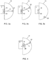
- the processing unit is configured to identify a predetermined part 22 of the occluding working equipment (see figure 1 and figures 3a -3c ), e.g. a hook, a load, a bucket, or a fork, to be visually presented in the merged image, and to display the predetermined part at the display unit. This is preferably performed by applying another pattern recognition algorithm to be set up in advance dependent on the presently used predetermined part of the working equipment.
- the merged image is presented to the operator on the display unit.
- the display unit may be any type of presentation unit configured and arranged such that the operator is provided with the necessary support in order to operate the working equipment safely and efficiently.
- the processing unit is configured to determine a presentation mode of the occluded part image, from a set of presentation modes including a transparent mode, wherein the working equipment defining the occluded part image is fully transparent and a semi-transparent mode, wherein the working equipment defining the occluded part image has a variable opacity.
- processing unit is configured to determine a presentation mode where an outer boundary of the occluded part image is indicated in the merged image.
- the boundary of the occluded part image may e.g. be indicated by a dashed line.
- FIGS 3a-3c illustrate various presentation modes.
- stereo cameras may be used for making 3D pictures, or for range imaging. Unlike most other approaches to depth sensing, such as structured light or time-of-flight measurements, stereo vision is a purely passive technology which also works in bright daylight.
- the image capturing system may comprise at least one camera unit, but may in addition also include one or many sensor units, e.g. angle sensor units, length sensor units, capable of capturing various supporting image data to be supplied to the processing unit.
- sensor units e.g. angle sensor units, length sensor units, capable of capturing various supporting image data to be supplied to the processing unit.
- the image capturing system applies the Lidar-technology.
- Lidar is sometimes considered an acronym of Light Detection and Ranging (sometimes Light Imaging, Detection, and Ranging), and is a surveying method that measures distance to a target by illuminating that target with a laser light.
- Lidar is popularly used to make high-resolution maps, with applications in geodesy, forestry, laser guidance, airborne laser swath mapping (ALSM), and laser altimetry.
- Lidar sometimes is called laser scanning and 3D scanning, with terrestrial, airborne, and mobile applications.
- the image capturing system also includes a 3D scanning device.
- a 3D scanner is a device that analyses a real-world object or environment to collect data on its shape and possibly its appearance (e.g. colour). The collected data can then be used to construct digital three-dimensional models.
- Many different technologies can be used to build these 3D-scanning devices; each technology comes with its own limitations, advantages and costs.
- Many limitations in the kind of objects that can be digitised are still present, for example, optical technologies encounter many difficulties with shiny, mirroring or transparent objects.
- industrial computed tomography scanning can be used to construct digital 3D models, applying non-destructive testing.
- 3D scanner The purpose of a 3D scanner is usually to create a point cloud of geometric samples on the surface of the subject. These points can then be used to extrapolate the shape of the subject (a process called reconstruction). If colour information is collected at each point, then the colours on the surface of the subject can also be determined.
- 3D scanners share several traits with cameras. Like most cameras, they have a cone-like field of view, and like cameras, they can only collect information about surfaces that are not obscured. While a camera collects colour information about surfaces within its field of view, a 3D scanner collects distance information about surfaces within its field of view. The "picture" produced by a 3D scanner describes the distance to a surface at each point in the picture. This allows the three dimensional position of each point in the picture to be identified.
- a so-called time-of-flight Lidar scanner may be used, together with the camera units, to produce a 3D model.
- the Lidar can aim its laser beam in a wide range: its head rotates horizontally, a mirror flips vertically.
- the laser beam is used to measure the distance to the first object on its path.
- the time-of-flight 3D laser scanner is an active scanner that uses laser light to probe the subject.
- a time-of-flight laser range finder finds the distance of a surface by timing the round-trip time of a pulse of light.
- a laser is used to emit a pulse of light and the amount of time before the reflected light is seen by a detector is measured. Since the speed of light c is known, the round-trip time determines the travel distance of the light, which is twice the distance between the scanner and the surface.
- the accuracy of a time-of-flight 3D laser scanner depends on how precisely we can measure the t; 3.3 picoseconds (approx.) is the time taken for light to travel 1 millimetre.
- the laser range finder only detects the distance of one point in its direction of view.
- the scanner scans its entire field of view one point at a time by changing the range finder's direction of view to scan different points.
- the view direction of the laser range finder can be changed either by rotating the range finder itself, or by using a system of rotating mirrors. The latter method is commonly used because mirrors are much lighter and can thus be rotated much faster and with greater accuracy.
- Typical time-of-flight 3D laser scanners can measure the distance of 10,000-100,000 points every second.
- the image capturing system uses a structured-light 3D scanner that projects a pattern of light on the subject and look at the deformation of the pattern on the subject.
- the pattern is projected onto the subject using either an LCD projector or other stable light source.
- a camera offset slightly from the pattern projector, looks at the shape of the pattern and calculates the distance of every point in the field of view.
- structured-light 3D scanners is speed and precision. Instead of scanning one point at a time, structured light scanners scan multiple points or the entire field of view at once. Scanning an entire field of view in a fraction of a second reduces or eliminates the problem of distortion from motion.
- the display unit may be a display arranged e.g. at a control unit or in the vehicle.
- the display unit 14 is a pair of glasses, for example of the type sold under the trademark Hololens.
- the pair of glasses is structured to present the 3D representation such that the 3D representation is overlaid on the transparent glasses through which a user observes the object.
- Various additional information may also be presented as overlaid information and preferably presented such that the additional information is presented close to an illustrated part of the object.
- the display unit 14 is a pair of virtual reality goggles. These types of goggles comprise two displays to be arranged in front of the operator's eyes. This variation is particularly advantageous when the operator has no direct line of sight to an object to be handled. Often VR goggles are provided with an orientation sensor that senses the orientation of the VR goggles. It may then be possible for a user to change the field of view to locate potential obstacles close to the load, provided that the object detecting device has a larger field of vision than the image presented at the displays of the VR goggles.
- the present invention also relates to a method applied by an operator assistance system for a vehicle provided with a working equipment. The method will now be described in detail with reference to the flow diagram shown in figure 5 .
- the assistance system is described above and comprises thus an image capturing system arranged at the vehicle and/or at the working equipment, and capable of capturing parameters related to images of the working equipment and of the environment outside said vehicle in a predetermined field of view.
- the assistance system further comprises a processing unit configured to receive image related parameter signals from the image capturing system and to process the image related parameter signals, and a display unit configured to present images to an operator.
- the image capturing system comprises at least two sensor unit assemblies capable of capturing parameters related to essentially overlapping images of said predetermined field of view.
- the sensor unit assembly may be a camera unit, an angle sensor, a length sensor, or any other sensor unit capable of capturing parameters related to images.
- the processing unit is configured to generate a merged image based upon said overlapping images.
- the method then comprises determining a shape and position of an image representation of the working equipment occluding a part of an image in the predetermined field of view, by processing image related signals, and determining if the part occluded by the working equipment is visible in any image in the predetermined field of view obtained by any of the other sensor unit assemblies. If the occluded part is visible by any of the other sensor unit assemblies, the method further comprises determining an occluded part image, being an image representation of the occluded part, in the field of view obtained by the other sensor unit assembly, merging, by said processing unit, the occluded part image into said merged image in said determined position of said working equipment, and finally displaying said merged image at said display unit.
- the method comprises applying a pattern recognition algorithm to identify any image representation of the working equipment in an image in the predetermined field of view by comparison to a set of image representations of the working equipment.
- the method preferably comprises identifying a predetermined part, e.g. a hook, a load, a fork, of the occluding working equipment to be visible in the merged image, and then displaying the predetermined part at the display unit.
- a predetermined part e.g. a hook, a load, a fork
- the method comprises determining a presentation mode of the occluded part image.
- the presentation mode is determined from a set of presentation modes including a transparent mode, wherein the working equipment defining the occluded part image is fully transparent, and a semi-transparent mode, wherein the working equipment defining the occluded part image has a variable opacity.
- the method further comprises determining a presentation mode where an outer boundary of the occluded part image is indicated in the merged image, e.g. by a dashed line.
Landscapes
- Engineering & Computer Science (AREA)
- Automation & Control Theory (AREA)
- Mechanical Engineering (AREA)
- Component Parts Of Construction Machinery (AREA)
Claims (13)
- Système d'assistance à opérateur (2) pour un véhicule (4) muni d'un équipement de travail (6), le système d'assistance (2) comprend un système de capture d'image (8) agencé au niveau dudit véhicule (4) et/ou au niveau dudit équipement de travail (6), et capable de capturer des paramètres relatifs à des images dudit équipement de travail (6) et de l'environnement à l'extérieur dudit véhicule (4) dans un champ de vision prédéterminé (10), une unité de traitement (12) configurée pour recevoir des signaux de paramètres relatifs à une image (14) à partir dudit système de capture d'image (8) et pour traiter lesdits signaux de paramètres relatifs à une image (14), et une unité d'affichage (16) configurée pour présenter des images à un opérateur, ledit système de capture d'image (8) comprend au moins deux ensembles d'unité de capteur (18, 20) capables de capturer des paramètres relatifs à des images se chevauchant sensiblement dudit champ de vision prédéterminé (10), et en ce que ladite unité de traitement (12) est configurée pour générer une image fusionnée sur la base desdites images se chevauchant,
caractérisé en ce que ladite unité de traitement (12) est configurée pour déterminer une forme et une position d'une représentation d'image dudit équipement de travail (6) occluant une partie d'une image dans le champ de vision prédéterminé (10), obtenue par l'un desdits ensembles d'unité de capteur (18, 20), en traitant des signaux relatifs à une image provenant d'au moins l'un des autres ensembles d'unité de capteur (18, 20), l'unité de traitement (12) est en outre configurée pour déterminer si la partie occluse par ledit équipement de travail (6) est visible dans une image quelconque dans le champ de vision prédéterminé (10) obtenue par l'un quelconque des autres ensembles d'unité de capteur, et si ladite partie est visible par l'un quelconque des autres ensembles d'unité de capteur (18, 20), une image de partie occluse, étant une représentation d'image de ladite partie occluse, est déterminée dans le champ de vision (10) obtenu par ledit autre ensemble d'unité de capteur (18, 20),
dans lequel ladite unité de traitement (12) est configurée pour fusionner ladite image de partie occluse en ladite image fusionnée dans ladite position déterminée dudit équipement de travail (6), et pour afficher ladite image fusionnée au niveau de ladite unité d'affichage (16). - Système d'assistance à opérateur (2) selon la revendication 1, dans lequel au moins l'un desdits ensembles d'unité de capteur (18, 20) comprend au moins un capteur d'angle et/ou au moins un capteur de longueur structuré pour être agencé au niveau dudit équipement de travail, et adapté pour mesurer des angles et des longueurs relatifs à des déplacements dudit équipement de travail, et au moins une unité de caméra (18, 20) montée au niveau dudit véhicule (4) et/ou au niveau dudit équipement de travail (6).
- Système d'assistance à opérateur (2) selon la revendication 1 ou 2, dans lequel lesdits ensembles d'unité de capteur (18, 20) comprennent au moins deux unités de caméra (18, 20) qui sont montées dans des positions de montage séparées au niveau dudit véhicule (4) par rapport audit équipement de travail (6), ou au niveau dudit équipement de travail (6), de sorte que différents côtés dudit équipement de travail (6) sont visibles sur des images obtenues par lesdites au moins deux unités de caméra (18, 20).
- Système d'assistance (2) selon l'une quelconque des revendications 1 à 3, dans lequel ladite unité de traitement (12) est pourvue d'un ensemble de représentations d'image de l'équipement de travail (6), et est en outre configurée pour appliquer un algorithme de reconnaissance de motif pour identifier toute représentation d'image de l'équipement de travail (6) dans une image dans le champ de vision prédéterminé par comparaison avec l'ensemble de représentations d'image.
- Système d'assistance (2) selon l'une quelconque des revendications 1 à 4, dans lequel ladite unité de traitement (12) est en outre configurée pour identifier une partie prédéterminée, par exemple un crochet, une charge, une fourche, dudit équipement de travail d'occlusion (6) comme étant visible dans ladite image fusionnée, et pour afficher ladite partie prédéterminée au niveau de ladite unité d'affichage (16).
- Système d'assistance (2) selon l'une quelconque des revendications 1 à 5, dans lequel ladite unité de traitement (12) est configurée pour déterminer un mode de présentation de ladite image de partie occluse, à partir d'un ensemble de modes de présentation comprenant un mode transparent, dans lequel ledit équipement de travail (6) définissant l'image de partie occluse est entièrement transparent, et un mode semi-transparent, dans lequel ledit équipement de travail (6) définissant ladite image de partie occluse présente une opacité variable.
- Système d'assistance (2) selon l'une quelconque des revendications 1 à 6, dans lequel ladite unité de traitement (12) est configurée pour déterminer un mode de présentation où une limite extérieure de l'image de partie occluse est indiquée dans l'image fusionnée.
- Système d'assistance (2) selon l'une quelconque des revendications 1 à 7, dans lequel ledit équipement de travail (6) est une grue, un bras démontable, une flèche ou un godet.
- Procédé appliqué par un système d'assistance à opérateur (2) pour un véhicule (4) muni d'un équipement de travail (6), le système d'assistance (2) comprend un système de capture d'image (8) agencé au niveau dudit véhicule et/ou au niveau de l'équipement de travail (6), et capable de capturer des paramètres relatifs à des images dudit équipement de travail (6) et de l'environnement à l'extérieur dudit véhicule (4) dans un champ de vision prédéterminé (10), une unité de traitement (12) configurée pour recevoir des signaux de paramètres relatifs à une image (14) à partir dudit système de capture d'image (8) et pour traiter lesdits signaux de paramètres relatifs à une image (14), et une unité d'affichage (16) configurée pour présenter des images à un opérateur, ledit système de capture d'image (8) comprend au moins deux ensembles d'unité de capteur (18, 20) capables de capturer des paramètres relatifs à des images se chevauchant sensiblement dudit champ de vision prédéterminé (10), et ladite unité de traitement (12) est configurée pour générer une image fusionnée sur la base desdites images se chevauchant,
caractérisé en ce que le procédé comprend les étapes consistant à :- déterminer une forme et une position d'une représentation d'image dudit équipement de travail (6) occluant une partie d'une image dans le champ de vision prédéterminé (10), en traitant des signaux relatifs à une image,- déterminer si la partie occluse par ledit équipement de travail (6) est visible dans une image quelconque dans le champ de vision prédéterminé (10) obtenue par l'un quelconque des autres ensembles d'unités de capteur (18, 20), et si ladite partie est visible par l'un quelconque des autres ensembles d'unités de capteur (18, 20), le procédé comprend en outre les étapes consistant à :- déterminer une image de partie occluse, qui est une représentation d'image de ladite partie occluse, dans le champ de vision (10), obtenue par ledit autre ensemble d'unité de capteur (18, 20),- fusionner, par l'intermédiaire de ladite unité de traitement (12), ladite image de partie occluse en ladite image fusionnée dans ladite position déterminée dudit équipement de travail (6),- afficher ladite image fusionnée au niveau de ladite unité d'affichage (16). - Procédé selon la revendication 9, comprenant en outre l'étape consistant à :- appliquer un algorithme de reconnaissance de motif pour identifier toute représentation d'image de l'équipement de travail (6) dans une image dans le champ de vision prédéterminé par comparaison à un ensemble de représentations d'image de l'équipement de travail (6).
- Procédé selon la revendication 9 ou 10, comprenant les étapes consistant à :- identifier une partie prédéterminée, par exemple un crochet, une charge, une fourche, dudit équipement de travail d'occlusion (6) comme étant visible dans ladite image fusionnée, et- afficher ladite partie prédéterminée au niveau de ladite unité d'affichage (16).
- Procédé selon l'une quelconque des revendications 9 à 11, comprenant en l'étape consistant à :- déterminer un mode de présentation de ladite image de partie occluse, à partir d'un ensemble de modes de présentation comprenant un mode transparent, dans lequel ledit équipement de travail (6) définissant l'image de partie occluse est entièrement transparent, et un mode semi-transparent, dans lequel ledit équipement de travail (6) définissant ladite image de partie occluse a une opacité variable.
- Procédé selon l'une quelconque des revendications 9 à 12, comprenant en l'étape consistant à :- déterminer un mode de présentation où une limite extérieure de l'image de partie occluse est indiquée dans l'image fusionnée.
Applications Claiming Priority (2)
| Application Number | Priority Date | Filing Date | Title |
|---|---|---|---|
| SE1751193 | 2017-09-26 | ||
| PCT/SE2018/050829 WO2019066693A1 (fr) | 2017-09-26 | 2018-08-16 | Système d'assistance à l'opérateur et procédé associé au système |
Publications (2)
| Publication Number | Publication Date |
|---|---|
| EP3687937A1 EP3687937A1 (fr) | 2020-08-05 |
| EP3687937B1 true EP3687937B1 (fr) | 2021-10-06 |
Family
ID=63442763
Family Applications (1)
| Application Number | Title | Priority Date | Filing Date |
|---|---|---|---|
| EP18762407.7A Active EP3687937B1 (fr) | 2017-09-26 | 2018-08-16 | Système d'assistance à l'opérateur et procédé associé au système |
Country Status (2)
| Country | Link |
|---|---|
| EP (1) | EP3687937B1 (fr) |
| WO (1) | WO2019066693A1 (fr) |
Families Citing this family (2)
| Publication number | Priority date | Publication date | Assignee | Title |
|---|---|---|---|---|
| DE102019112954A1 (de) * | 2019-05-16 | 2020-11-19 | Jungheinrich Aktiengesellschaft | Verfahren zur Lagerungsunterstützung bei einem Flurförderzeug und Flurförderzeug |
| JP7613609B2 (ja) * | 2021-11-30 | 2025-01-15 | 株式会社タダノ | 操縦支援システム及び作業車両 |
Family Cites Families (3)
| Publication number | Priority date | Publication date | Assignee | Title |
|---|---|---|---|---|
| JP4951639B2 (ja) * | 2009-03-02 | 2012-06-13 | 日立建機株式会社 | 周囲監視装置を備えた作業機械 |
| JP5941663B2 (ja) * | 2011-11-30 | 2016-06-29 | 住友建機株式会社 | 建設機械用モニタシステム |
| JP6258594B2 (ja) * | 2013-03-28 | 2018-01-10 | 三井造船株式会社 | クレーンの運転室及びクレーン |
-
2018
- 2018-08-16 WO PCT/SE2018/050829 patent/WO2019066693A1/fr not_active Ceased
- 2018-08-16 EP EP18762407.7A patent/EP3687937B1/fr active Active
Also Published As
| Publication number | Publication date |
|---|---|
| WO2019066693A1 (fr) | 2019-04-04 |
| EP3687937A1 (fr) | 2020-08-05 |
Similar Documents
| Publication | Publication Date | Title |
|---|---|---|
| EP3606861B1 (fr) | Système et procédé d'aide à la conduite automobile | |
| EP3589575B1 (fr) | Véhicule équipé d'un agencement pour déterminer une représentation tridimensionnelle d'un élément mobile | |
| EP3235773B1 (fr) | Dispositif d'obtention d'informations environnementales pour un véhicule de travail | |
| WO2018169467A1 (fr) | Véhicule équipé d'une grue dotée d'un dispositif de détection d'objet | |
| US7974461B2 (en) | Method and apparatus for displaying a calculated geometric entity within one or more 3D rangefinder data sets | |
| US9279662B2 (en) | Laser scanner | |
| US7777761B2 (en) | Method and apparatus for specifying and displaying measurements within a 3D rangefinder data set | |
| JP5667638B2 (ja) | 作業機械の周辺監視装置 | |
| US20060193179A1 (en) | Method and apparatus for determining the geometric correspondence between multiple 3D rangefinder data sets | |
| EP3657455B1 (fr) | Procédés et systèmes de détection d'intrusions dans un volume surveillé | |
| AU2017318897A1 (en) | Image display system for work machine | |
| JPH06293236A (ja) | 走行環境監視装置 | |
| WO2017034744A1 (fr) | Système permettant d'améliorer la visibilité de l'environnement d'une machine pour l'opérateur | |
| JP2020142903A (ja) | 画像処理装置、および制御プログラム | |
| EP3687937B1 (fr) | Système d'assistance à l'opérateur et procédé associé au système | |
| CN104228683A (zh) | 用于运行调车和/或泊车用的驾驶员辅助系统的方法 | |
| EP3524926B1 (fr) | Système de réalité augmentée avec fonctionnalité de définition de périmètres et méthode d'inspection correspondante | |
| JP2020040769A (ja) | フォークリフト用の画像処理装置、および制御プログラム | |
| KR102332616B1 (ko) | 라이다와 ar을 이용한 건설 장비용 디스플레이 장치 | |
| JP2002354466A (ja) | 車両用周囲監視装置 | |
| US20230300459A1 (en) | Software camera view lock allowing editing of drawing without any shift in the view | |
| US20260009206A1 (en) | Blind spot display device for construction equipment | |
| EP4389993A1 (fr) | Visualisation d'objet dans un équipement lourd de construction | |
| EP4655612A1 (fr) | Localisation et suivi basés sur une image à l'aide de données tridimensionnelles | |
| JP2000171222A (ja) | 3次元入力方法及び3次元入力装置 |
Legal Events
| Date | Code | Title | Description |
|---|---|---|---|
| STAA | Information on the status of an ep patent application or granted ep patent |
Free format text: STATUS: UNKNOWN |
|
| STAA | Information on the status of an ep patent application or granted ep patent |
Free format text: STATUS: THE INTERNATIONAL PUBLICATION HAS BEEN MADE |
|
| PUAI | Public reference made under article 153(3) epc to a published international application that has entered the european phase |
Free format text: ORIGINAL CODE: 0009012 |
|
| STAA | Information on the status of an ep patent application or granted ep patent |
Free format text: STATUS: REQUEST FOR EXAMINATION WAS MADE |
|
| 17P | Request for examination filed |
Effective date: 20200228 |
|
| AK | Designated contracting states |
Kind code of ref document: A1 Designated state(s): AL AT BE BG CH CY CZ DE DK EE ES FI FR GB GR HR HU IE IS IT LI LT LU LV MC MK MT NL NO PL PT RO RS SE SI SK SM TR |
|
| AX | Request for extension of the european patent |
Extension state: BA ME |
|
| DAV | Request for validation of the european patent (deleted) | ||
| DAX | Request for extension of the european patent (deleted) | ||
| STAA | Information on the status of an ep patent application or granted ep patent |
Free format text: STATUS: EXAMINATION IS IN PROGRESS |
|
| 17Q | First examination report despatched |
Effective date: 20210325 |
|
| RAP1 | Party data changed (applicant data changed or rights of an application transferred) |
Owner name: HIAB AB |
|
| GRAP | Despatch of communication of intention to grant a patent |
Free format text: ORIGINAL CODE: EPIDOSNIGR1 |
|
| STAA | Information on the status of an ep patent application or granted ep patent |
Free format text: STATUS: GRANT OF PATENT IS INTENDED |
|
| INTG | Intention to grant announced |
Effective date: 20210615 |
|
| GRAS | Grant fee paid |
Free format text: ORIGINAL CODE: EPIDOSNIGR3 |
|
| GRAA | (expected) grant |
Free format text: ORIGINAL CODE: 0009210 |
|
| STAA | Information on the status of an ep patent application or granted ep patent |
Free format text: STATUS: THE PATENT HAS BEEN GRANTED |
|
| AK | Designated contracting states |
Kind code of ref document: B1 Designated state(s): AL AT BE BG CH CY CZ DE DK EE ES FI FR GB GR HR HU IE IS IT LI LT LU LV MC MK MT NL NO PL PT RO RS SE SI SK SM TR |
|
| REG | Reference to a national code |
Ref country code: GB Ref legal event code: FG4D |
|
| REG | Reference to a national code |
Ref country code: CH Ref legal event code: EP Ref country code: AT Ref legal event code: REF Ref document number: 1436070 Country of ref document: AT Kind code of ref document: T Effective date: 20211015 |
|
| REG | Reference to a national code |
Ref country code: DE Ref legal event code: R096 Ref document number: 602018024707 Country of ref document: DE |
|
| REG | Reference to a national code |
Ref country code: IE Ref legal event code: FG4D |
|
| REG | Reference to a national code |
Ref country code: LT Ref legal event code: MG9D |
|
| REG | Reference to a national code |
Ref country code: NL Ref legal event code: MP Effective date: 20211006 |
|
| PG25 | Lapsed in a contracting state [announced via postgrant information from national office to epo] |
Ref country code: RS Free format text: LAPSE BECAUSE OF FAILURE TO SUBMIT A TRANSLATION OF THE DESCRIPTION OR TO PAY THE FEE WITHIN THE PRESCRIBED TIME-LIMIT Effective date: 20211006 Ref country code: LT Free format text: LAPSE BECAUSE OF FAILURE TO SUBMIT A TRANSLATION OF THE DESCRIPTION OR TO PAY THE FEE WITHIN THE PRESCRIBED TIME-LIMIT Effective date: 20211006 Ref country code: FI Free format text: LAPSE BECAUSE OF FAILURE TO SUBMIT A TRANSLATION OF THE DESCRIPTION OR TO PAY THE FEE WITHIN THE PRESCRIBED TIME-LIMIT Effective date: 20211006 Ref country code: BG Free format text: LAPSE BECAUSE OF FAILURE TO SUBMIT A TRANSLATION OF THE DESCRIPTION OR TO PAY THE FEE WITHIN THE PRESCRIBED TIME-LIMIT Effective date: 20220106 |
|
| PG25 | Lapsed in a contracting state [announced via postgrant information from national office to epo] |
Ref country code: IS Free format text: LAPSE BECAUSE OF FAILURE TO SUBMIT A TRANSLATION OF THE DESCRIPTION OR TO PAY THE FEE WITHIN THE PRESCRIBED TIME-LIMIT Effective date: 20220206 Ref country code: SE Free format text: LAPSE BECAUSE OF FAILURE TO SUBMIT A TRANSLATION OF THE DESCRIPTION OR TO PAY THE FEE WITHIN THE PRESCRIBED TIME-LIMIT Effective date: 20211006 Ref country code: PT Free format text: LAPSE BECAUSE OF FAILURE TO SUBMIT A TRANSLATION OF THE DESCRIPTION OR TO PAY THE FEE WITHIN THE PRESCRIBED TIME-LIMIT Effective date: 20220207 Ref country code: PL Free format text: LAPSE BECAUSE OF FAILURE TO SUBMIT A TRANSLATION OF THE DESCRIPTION OR TO PAY THE FEE WITHIN THE PRESCRIBED TIME-LIMIT Effective date: 20211006 Ref country code: NO Free format text: LAPSE BECAUSE OF FAILURE TO SUBMIT A TRANSLATION OF THE DESCRIPTION OR TO PAY THE FEE WITHIN THE PRESCRIBED TIME-LIMIT Effective date: 20220106 Ref country code: NL Free format text: LAPSE BECAUSE OF FAILURE TO SUBMIT A TRANSLATION OF THE DESCRIPTION OR TO PAY THE FEE WITHIN THE PRESCRIBED TIME-LIMIT Effective date: 20211006 Ref country code: LV Free format text: LAPSE BECAUSE OF FAILURE TO SUBMIT A TRANSLATION OF THE DESCRIPTION OR TO PAY THE FEE WITHIN THE PRESCRIBED TIME-LIMIT Effective date: 20211006 Ref country code: HR Free format text: LAPSE BECAUSE OF FAILURE TO SUBMIT A TRANSLATION OF THE DESCRIPTION OR TO PAY THE FEE WITHIN THE PRESCRIBED TIME-LIMIT Effective date: 20211006 Ref country code: GR Free format text: LAPSE BECAUSE OF FAILURE TO SUBMIT A TRANSLATION OF THE DESCRIPTION OR TO PAY THE FEE WITHIN THE PRESCRIBED TIME-LIMIT Effective date: 20220107 Ref country code: ES Free format text: LAPSE BECAUSE OF FAILURE TO SUBMIT A TRANSLATION OF THE DESCRIPTION OR TO PAY THE FEE WITHIN THE PRESCRIBED TIME-LIMIT Effective date: 20211006 |
|
| REG | Reference to a national code |
Ref country code: DE Ref legal event code: R097 Ref document number: 602018024707 Country of ref document: DE |
|
| PG25 | Lapsed in a contracting state [announced via postgrant information from national office to epo] |
Ref country code: SM Free format text: LAPSE BECAUSE OF FAILURE TO SUBMIT A TRANSLATION OF THE DESCRIPTION OR TO PAY THE FEE WITHIN THE PRESCRIBED TIME-LIMIT Effective date: 20211006 Ref country code: SK Free format text: LAPSE BECAUSE OF FAILURE TO SUBMIT A TRANSLATION OF THE DESCRIPTION OR TO PAY THE FEE WITHIN THE PRESCRIBED TIME-LIMIT Effective date: 20211006 Ref country code: RO Free format text: LAPSE BECAUSE OF FAILURE TO SUBMIT A TRANSLATION OF THE DESCRIPTION OR TO PAY THE FEE WITHIN THE PRESCRIBED TIME-LIMIT Effective date: 20211006 Ref country code: EE Free format text: LAPSE BECAUSE OF FAILURE TO SUBMIT A TRANSLATION OF THE DESCRIPTION OR TO PAY THE FEE WITHIN THE PRESCRIBED TIME-LIMIT Effective date: 20211006 Ref country code: DK Free format text: LAPSE BECAUSE OF FAILURE TO SUBMIT A TRANSLATION OF THE DESCRIPTION OR TO PAY THE FEE WITHIN THE PRESCRIBED TIME-LIMIT Effective date: 20211006 Ref country code: CZ Free format text: LAPSE BECAUSE OF FAILURE TO SUBMIT A TRANSLATION OF THE DESCRIPTION OR TO PAY THE FEE WITHIN THE PRESCRIBED TIME-LIMIT Effective date: 20211006 |
|
| PLBE | No opposition filed within time limit |
Free format text: ORIGINAL CODE: 0009261 |
|
| STAA | Information on the status of an ep patent application or granted ep patent |
Free format text: STATUS: NO OPPOSITION FILED WITHIN TIME LIMIT |
|
| 26N | No opposition filed |
Effective date: 20220707 |
|
| PG25 | Lapsed in a contracting state [announced via postgrant information from national office to epo] |
Ref country code: AL Free format text: LAPSE BECAUSE OF FAILURE TO SUBMIT A TRANSLATION OF THE DESCRIPTION OR TO PAY THE FEE WITHIN THE PRESCRIBED TIME-LIMIT Effective date: 20211006 |
|
| PG25 | Lapsed in a contracting state [announced via postgrant information from national office to epo] |
Ref country code: SI Free format text: LAPSE BECAUSE OF FAILURE TO SUBMIT A TRANSLATION OF THE DESCRIPTION OR TO PAY THE FEE WITHIN THE PRESCRIBED TIME-LIMIT Effective date: 20211006 |
|
| PG25 | Lapsed in a contracting state [announced via postgrant information from national office to epo] |
Ref country code: MC Free format text: LAPSE BECAUSE OF FAILURE TO SUBMIT A TRANSLATION OF THE DESCRIPTION OR TO PAY THE FEE WITHIN THE PRESCRIBED TIME-LIMIT Effective date: 20211006 |
|
| REG | Reference to a national code |
Ref country code: CH Ref legal event code: PL |
|
| PG25 | Lapsed in a contracting state [announced via postgrant information from national office to epo] |
Ref country code: LU Free format text: LAPSE BECAUSE OF NON-PAYMENT OF DUE FEES Effective date: 20220816 Ref country code: LI Free format text: LAPSE BECAUSE OF NON-PAYMENT OF DUE FEES Effective date: 20220831 Ref country code: CH Free format text: LAPSE BECAUSE OF NON-PAYMENT OF DUE FEES Effective date: 20220831 |
|
| REG | Reference to a national code |
Ref country code: BE Ref legal event code: MM Effective date: 20220831 |
|
| PG25 | Lapsed in a contracting state [announced via postgrant information from national office to epo] |
Ref country code: IT Free format text: LAPSE BECAUSE OF FAILURE TO SUBMIT A TRANSLATION OF THE DESCRIPTION OR TO PAY THE FEE WITHIN THE PRESCRIBED TIME-LIMIT Effective date: 20211006 |
|
| PG25 | Lapsed in a contracting state [announced via postgrant information from national office to epo] |
Ref country code: IE Free format text: LAPSE BECAUSE OF NON-PAYMENT OF DUE FEES Effective date: 20220816 |
|
| PG25 | Lapsed in a contracting state [announced via postgrant information from national office to epo] |
Ref country code: BE Free format text: LAPSE BECAUSE OF NON-PAYMENT OF DUE FEES Effective date: 20220831 |
|
| REG | Reference to a national code |
Ref country code: AT Ref legal event code: UEP Ref document number: 1436070 Country of ref document: AT Kind code of ref document: T Effective date: 20211006 |
|
| PG25 | Lapsed in a contracting state [announced via postgrant information from national office to epo] |
Ref country code: CY Free format text: LAPSE BECAUSE OF FAILURE TO SUBMIT A TRANSLATION OF THE DESCRIPTION OR TO PAY THE FEE WITHIN THE PRESCRIBED TIME-LIMIT Effective date: 20211006 |
|
| PG25 | Lapsed in a contracting state [announced via postgrant information from national office to epo] |
Ref country code: MK Free format text: LAPSE BECAUSE OF FAILURE TO SUBMIT A TRANSLATION OF THE DESCRIPTION OR TO PAY THE FEE WITHIN THE PRESCRIBED TIME-LIMIT Effective date: 20211006 Ref country code: HU Free format text: LAPSE BECAUSE OF FAILURE TO SUBMIT A TRANSLATION OF THE DESCRIPTION OR TO PAY THE FEE WITHIN THE PRESCRIBED TIME-LIMIT; INVALID AB INITIO Effective date: 20180816 |
|
| REG | Reference to a national code |
Ref country code: DE Ref legal event code: R081 Ref document number: 602018024707 Country of ref document: DE Owner name: HIAB AB, SE Free format text: FORMER OWNER: HIAB AB, KISTA, SE |
|
| PG25 | Lapsed in a contracting state [announced via postgrant information from national office to epo] |
Ref country code: MT Free format text: LAPSE BECAUSE OF FAILURE TO SUBMIT A TRANSLATION OF THE DESCRIPTION OR TO PAY THE FEE WITHIN THE PRESCRIBED TIME-LIMIT Effective date: 20211006 |
|
| PGFP | Annual fee paid to national office [announced via postgrant information from national office to epo] |
Ref country code: DE Payment date: 20250827 Year of fee payment: 8 |
|
| PGFP | Annual fee paid to national office [announced via postgrant information from national office to epo] |
Ref country code: GB Payment date: 20250826 Year of fee payment: 8 |
|
| PGFP | Annual fee paid to national office [announced via postgrant information from national office to epo] |
Ref country code: FR Payment date: 20250825 Year of fee payment: 8 Ref country code: AT Payment date: 20250819 Year of fee payment: 8 |
|
| PG25 | Lapsed in a contracting state [announced via postgrant information from national office to epo] |
Ref country code: TR Free format text: LAPSE BECAUSE OF FAILURE TO SUBMIT A TRANSLATION OF THE DESCRIPTION OR TO PAY THE FEE WITHIN THE PRESCRIBED TIME-LIMIT Effective date: 20211006 |