EP3688367B1 - Dispositif d'éclairage de véhicule à moteur comprenant des systèmes de micro-optiques comprenant des micro-optiques d'entrée subdivisées - Google Patents
Dispositif d'éclairage de véhicule à moteur comprenant des systèmes de micro-optiques comprenant des micro-optiques d'entrée subdivisées Download PDFInfo
- Publication number
- EP3688367B1 EP3688367B1 EP18752675.1A EP18752675A EP3688367B1 EP 3688367 B1 EP3688367 B1 EP 3688367B1 EP 18752675 A EP18752675 A EP 18752675A EP 3688367 B1 EP3688367 B1 EP 3688367B1
- Authority
- EP
- European Patent Office
- Prior art keywords
- micro
- optics
- entrance
- exit
- light
- Prior art date
- Legal status (The legal status is an assumption and is not a legal conclusion. Google has not performed a legal analysis and makes no representation as to the accuracy of the status listed.)
- Active
Links
Images




Classifications
-
- F—MECHANICAL ENGINEERING; LIGHTING; HEATING; WEAPONS; BLASTING
- F21—LIGHTING
- F21S—NON-PORTABLE LIGHTING DEVICES; SYSTEMS THEREOF; VEHICLE LIGHTING DEVICES SPECIALLY ADAPTED FOR VEHICLE EXTERIORS
- F21S41/00—Illuminating devices specially adapted for vehicle exteriors, e.g. headlamps
- F21S41/20—Illuminating devices specially adapted for vehicle exteriors, e.g. headlamps characterised by refractors, transparent cover plates, light guides or filters
- F21S41/25—Projection lenses
- F21S41/275—Lens surfaces, e.g. coatings or surface structures
-
- F—MECHANICAL ENGINEERING; LIGHTING; HEATING; WEAPONS; BLASTING
- F21—LIGHTING
- F21S—NON-PORTABLE LIGHTING DEVICES; SYSTEMS THEREOF; VEHICLE LIGHTING DEVICES SPECIALLY ADAPTED FOR VEHICLE EXTERIORS
- F21S41/00—Illuminating devices specially adapted for vehicle exteriors, e.g. headlamps
- F21S41/10—Illuminating devices specially adapted for vehicle exteriors, e.g. headlamps characterised by the light source
- F21S41/14—Illuminating devices specially adapted for vehicle exteriors, e.g. headlamps characterised by the light source characterised by the type of light source
- F21S41/141—Light emitting diodes [LED]
- F21S41/143—Light emitting diodes [LED] the main emission direction of the LED being parallel to the optical axis of the illuminating device
-
- F—MECHANICAL ENGINEERING; LIGHTING; HEATING; WEAPONS; BLASTING
- F21—LIGHTING
- F21S—NON-PORTABLE LIGHTING DEVICES; SYSTEMS THEREOF; VEHICLE LIGHTING DEVICES SPECIALLY ADAPTED FOR VEHICLE EXTERIORS
- F21S41/00—Illuminating devices specially adapted for vehicle exteriors, e.g. headlamps
- F21S41/20—Illuminating devices specially adapted for vehicle exteriors, e.g. headlamps characterised by refractors, transparent cover plates, light guides or filters
- F21S41/25—Projection lenses
- F21S41/265—Composite lenses; Lenses with a patch-like shape
-
- F—MECHANICAL ENGINEERING; LIGHTING; HEATING; WEAPONS; BLASTING
- F21—LIGHTING
- F21S—NON-PORTABLE LIGHTING DEVICES; SYSTEMS THEREOF; VEHICLE LIGHTING DEVICES SPECIALLY ADAPTED FOR VEHICLE EXTERIORS
- F21S41/00—Illuminating devices specially adapted for vehicle exteriors, e.g. headlamps
- F21S41/20—Illuminating devices specially adapted for vehicle exteriors, e.g. headlamps characterised by refractors, transparent cover plates, light guides or filters
- F21S41/285—Refractors, transparent cover plates, light guides or filters not provided in groups F21S41/24 - F21S41/2805
-
- F—MECHANICAL ENGINEERING; LIGHTING; HEATING; WEAPONS; BLASTING
- F21—LIGHTING
- F21S—NON-PORTABLE LIGHTING DEVICES; SYSTEMS THEREOF; VEHICLE LIGHTING DEVICES SPECIALLY ADAPTED FOR VEHICLE EXTERIORS
- F21S41/00—Illuminating devices specially adapted for vehicle exteriors, e.g. headlamps
- F21S41/40—Illuminating devices specially adapted for vehicle exteriors, e.g. headlamps characterised by screens, non-reflecting members, light-shielding members or fixed shades
- F21S41/43—Illuminating devices specially adapted for vehicle exteriors, e.g. headlamps characterised by screens, non-reflecting members, light-shielding members or fixed shades characterised by the shape thereof
-
- G—PHYSICS
- G02—OPTICS
- G02B—OPTICAL ELEMENTS, SYSTEMS OR APPARATUS
- G02B27/00—Optical systems or apparatus not provided for by any of the groups G02B1/00 - G02B26/00, G02B30/00
- G02B27/09—Beam shaping, e.g. changing the cross-sectional area, not otherwise provided for
- G02B27/0938—Using specific optical elements
- G02B27/095—Refractive optical elements
- G02B27/0955—Lenses
- G02B27/0961—Lens arrays
-
- G—PHYSICS
- G02—OPTICS
- G02B—OPTICAL ELEMENTS, SYSTEMS OR APPARATUS
- G02B3/00—Simple or compound lenses
- G02B3/0006—Arrays
- G02B3/0037—Arrays characterized by the distribution or form of lenses
- G02B3/0062—Stacked lens arrays, i.e. refractive surfaces arranged in at least two planes, without structurally separate optical elements in-between
Definitions
- the invention relates to a motor vehicle lighting device for generating a light distribution, comprising an optical imaging system and at least one light source assigned to the optical imaging system, the optical imaging system comprising a collimator, entry optics and exit optics, the collimator being arranged between the at least one light source and the entry optics and for this purpose is set up to collimate light beams generated by the at least one light source in order to generate collimated light beams in this way and to direct the collimated light beams onto the entry optics of the optical imaging system, the entry optics having a plurality of micro entry optics formed integrally with one another, wherein a first optical axis is assigned to each micro-entry optical system, with all first optical axes running in the same direction, preferably parallel to one another, which direction of propagation g direction of the collimated light beams, the exit optics having a plurality of micro exit optics formed integrally with one another, each micro exit optic being assigned a second optical axis, all second optical axes running in
- a projection light module for a motor vehicle headlight which can comprise an entry optic, an exit optic and a diaphragm device. Both the entry optics and the exit optics are designed as micro-optics arrays.
- a micro entry optic, a micro exit optic and possibly a diaphragm arranged between these two optics form an optical imaging system with which part of the common light distribution is generated.
- a partial intermediate image projected as this part of the light distribution in front of the motor vehicle lighting device is generated by the corresponding individual micro entry optics.
- This is disadvantageous in that only the degrees of freedom of each micro-entry optics can be used to shape the light distribution.
- the object of the present invention is to further develop the motor vehicle lighting device of the type mentioned above in such a way that the number of possibilities for modifying and/or setting and/or finely adjusting the emitted light distribution is increased.
- a motor vehicle lighting device in which at least two differently designed micro entry optics are assigned to each micro exit optics in such a way that the at least two differently designed micro entry optics are incident and at least two differently designed micro entry optics pass through them Light rays impinge exclusively on the micro-exit optics associated with the at least two differently designed micro-entry optics and, after passing through the micro-exit optics, form different partial areas of the light distribution.
- the design and/or the shape of the individual micro entrance optics can be used to bring about specific, desired changes in the emitted light distribution.
- the at least two micro entry optics are configured as an NxM micro entry optics array, where N ⁇ 2 or M ⁇ 2, preferably as a 3x3 micro entry optics array, or in an NxM micro - entrance optics array, where N ⁇ 2 or M ⁇ 2, are preferably arranged in a 3x3 micro entrance optics array.
- the entry optics is set up to generate an intermediate image (with the help of the at least two differently designed micro entry optics), which intermediate image is imaged by the exit optics in front of the motor vehicle lighting device, the intermediate image preferably being in front of the exit optics.
- micro entry optics are designed as lenses. Compared to conventional lenses, these lenses have a smaller diameter and consequently also a smaller middle thickness. This can be advantageous with regard to the manufacture of the lenses. Furthermore, this also results in a reduction in the thickness of the entire entrance optics. This enables the entry optics and, as a result, the entire optical imaging system to have a smaller linear expansion, and therefore brings advantages in terms of installation space. In addition, lenses with a small center thickness have less wall thickness variation. This means that manufacturing tolerances can be kept low.
- At least one first micro entry optics of the at least two differently designed micro entry optics assigned and/or corresponding to the micro exit optics is designed in such a way and corresponds to and/or assigned to the micro exit optics in such a way that collimated light beams incident on this at least one first micro entry optics propagate in the direction of a HV range of the light distribution after exiting from the micro exit optics.
- the at least one first micro entry optics can be designed as a plano-convex lens, for example.
- micro entry optics are designed as lenses, for example free-form lenses, and each micro exit optic corresponds to and/or is assigned a 3x3 micro entry optics array, for example, then a central lens of the array can focus more strongly than its neighbors in order to in this way to achieve a higher maximum illuminance in the HV point.
- HV area is to be understood as an area around the HV point, which extends approximately from -5° to +5° horizontally and from -5° to +5° vertically.
- the vertical extension of the HV range is preferably from -2° to +2° when the motor vehicle lighting device is used to implement a driving light function (e.g. generating a low beam or high beam distribution) and from -5° to +5° when the motor vehicle lighting device is used to implement Signal light distribution (e.g. generating a turning light distribution) is used.
- At least one second micro entrance optics of the at least two differently designed micro entrance optics assigned and/or corresponding to the micro exit optics is designed in such a way and corresponds to and/or assigned to the micro exit optics in such a way that collimated on these at least one second micro entry optics incident light beams after emerging from the micro exit optics in the direction outside a HV range of the light distribution propagate.
- the at least one second micro entry optics can be designed, for example, as a plano-concave lens or as a plano-concave lens piece or as a plano-convex lens piece.
- micro entry optics are designed as lenses, for example free-form lenses, and each micro exit optic corresponds and/or is assigned, for example, a 3x3 micro entry optics array, then, for example, those adjacent to the central lens of the array , the lenses surrounding this central lens focus weaker than the central lens, in order to determine the width of the light distribution or form edges of the light distribution in this way.
- the light entry surfaces of the micro entry optics are designed as free-form surfaces.
- a free-form surface is understood to mean a surface that is typical of a free-form lens.
- the light entry surface of the at least one first micro entry optics of the at least two micro entry optics can be curved differently in the horizontal and in the vertical direction.
- the light entry surface of the at least one second micro entry optics of the at least two micro entry optics can also be designed as a free-form surface.
- the course of the free-form surfaces of the light entry surfaces of the at least one first and at least one second micro entry optics mentioned are different (see in particular Figures 5 to 8 ).
- each micro-entry optic can have its own curvature of the light entry surface, which curvature also differs from the curvature the light exit surface of the micro exit optics can differ. This makes it possible to vary the parameters, such as focal length, collimation strength of a light beam passing through, etc., of each individual micro-optical system independently of the parameters of the other micro-optical systems. These parameters are often referred to in the technical literature as "degrees of freedom of the optical system".
- the term "vertical”/"horizontal” refers to an axis of one with the motor vehicle lighting device connected coordinate system, which is aligned vertically/horizontally when the motor vehicle lighting device is in a position which position corresponds to an installation state of the motor vehicle lighting device in a motor vehicle.
- a light module 1 which can correspond to a motor vehicle lighting device according to the invention.
- a light module can be used, for example, in a headlight of a motor vehicle and can be set up to generate a light distribution that conforms to the law, for example.
- the legal requirements and standards can be different for different countries and/or regions of the world.
- the light module according to the invention can meet the specifications in several countries/regions (eg EU, North America, Japan and China) at the same time.
- the light module includes a optical imaging system 2 and at least one light source 3 assigned to the optical imaging system.
- the optical imaging system has a collimator 4, which is set up to collimate light beams generated by the at least one light source 3, entry optics 5 and exit optics 6.
- the collimator is usually arranged between the at least one light source 3 and the entry optics 5 .
- the collimator 4 can be designed, for example, as a TIR lens (TIR for Total Internal Reflection).
- a collimator can be designed as an optical body made of a material whose refractive index is greater than the refractive index of air (at normal operating temperatures of a motor vehicle headlight), such as glass or plastic, which optical body transmits the light due to the total inner reflection" known physical effect from its light in-coupling surface to its light out-coupling surface with almost no losses. Essentially all of the light refracted at the light output surface of the optical body propagates through the air, preferably in a predetermined direction (in figure 1 - direction Z), off.
- the collimator 4 is designed as a reflector, i.e. as a surface reflecting (primarily visible) light, which preferably directs light rays propagating through air in a predetermined direction (in figure 1 - Direction Z) deflects.
- the light module can also include other parts such as heat sinks, supporting frames, mechanical and/or electrical adjustment devices, covers and so on and immediately.
- other parts such as heat sinks, supporting frames, mechanical and/or electrical adjustment devices, covers and so on and immediately.
- the parts of the light module that can prove useful in the presentation of the inventive idea are shown schematically here. A detailed description of the above-mentioned standard components of a light module is omitted.
- the light generated by the light source 3, which reaches the collimator 4, is formed by the collimator into a light beam, preferably made up of collimated light beams 7, with the collimated light beams being aligned essentially parallel to one another (see, for example, Figures 5 to 8 ).
- essentially parallel means that the collimated beams only run parallel if the light source is designed as an ideal point light source.
- this mathematical abstraction is very rare in modern vehicle construction.
- extended (not punctiform) light sources for example an LED light source
- the collimated light beams 7 are incident on the entry optics 5 of the optical imaging system 2 .
- the light module 1 shown is particularly suitable for generating a high beam distribution.
- figure 2 shows the light module 1 figure 1 , in which the optical imaging system 2 comprises a diaphragm device 10, which is arranged between the entry optics 5 and the exit optics 6.
- the optical imaging system 2 comprises a diaphragm device 10, which is arranged between the entry optics 5 and the exit optics 6.
- diaphragm devices 10 can prove to be useful, for example, when generating low beam distributions.
- the light-dark boundary of a low-beam light distribution can be produced by forming diaphragm edges of the diaphragms of the diaphragm device 10 arranged in an intermediate image plane.
- the optical imaging system 2 can also include other lighting devices (not shown here), which, for example, as in AT 517 885 A1 is described in detail by the applicant, are intended to correct imaging errors.
- other lighting devices not shown here
- the optical imaging systems with such lighting devices and in particular for a detailed description of the lighting device, whose optically effective edges to form a low beam distribution and / or to correct imaging errors, reference is made to the documents AT 514 967 B1 and AT 517 885 A1 explicitly referenced.
- FIG 3 shows an enlarged section of the light module figure 2 .
- the entry optics 5 have a plurality of micro entry optics 50 to 58 formed in one piece with one another. Each micro entrance optics 50 to 58 is assigned a first optical axis 50a to 58a, with all first optical axes 50a to 58a running in the same direction Z, which direction Z corresponds to the direction of propagation of the collimated light beams 7 (see also Figures 5 to 8 ).
- the exit optics 6 also have a plurality of micro exit optics 60 ( figure 3 shows one of them), with each micro-exit optics 60 being assigned a second optical axis 60a and all second optical axes 60a pointing in the same direction (direction Z in figure 3 ) get lost.
- each micro entry optics 50 to 58 has one of the collimated light beams 7 facing, preferably curved, for example convex or free-form light entry surface 50b to 58b and a preferably flat light exit surface 50c to 58c facing the exit optics 6, with all light exit surfaces 50c to 58c forming a common, preferably flat surface 8 - the light exit surface of the entry optics (see also figures 2 and 5 ).
- each micro exit optics 60 is assigned at least two differently designed micro entry optics 50 to 58 in such a way that light beams 9a to 9c (see also Figures 5 to 8 ). -area and edges or edge areas) of the light distribution (see also Figures 5 to 8 ).
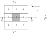
- each micro exit optics is assigned a 3x3 micro entry optics array (see also figure 4 ), wherein a micro entrance optics 54 located in a center of the micro entrance optics array - center optics - is designed differently from the other micro entrance optics 50 to 53 and 55 to 58 of the micro entrance optics array.
- micro entry optics 50 to 53 and 55 to 58 of the micro entry optics array all have to be of the same design. It is quite conceivable that the micro entry optics 51, 53, 55, 57 are a first group of the same micro entry optics of the micro entry optics array and the micro entry optics 50, 52, 56, 58 are a second group of the same micro entry optics of the Form micro entry optics arrays, wherein the micro entry optics from the first and from the second group can be designed differently.
- An embodiment in which the micro entrance optics of the micro entrance optics array are designed in this way is often referred to as a "symmetrical design".
- the micro entry optics belonging to the first or the second group are not all of the same design.
- a first part of the first group of micro entry optics - the micro entry optics 53 and 55 - can be of the same design ("horizontally symmetrical design"), with the remaining micro entry optics of the first group - the micro entry optics 51 and 57 - can form a second part of the first group and can be identical to each other but different from the entry microoptics of the first part of the first group ("vertically symmetrical layout").
- all micro entry optics of the second group are all designed differently and, for example, not a single micro entry optic of the first group is the same or congruent.
- the at least two micro entrance optics 50 to 58 can be designed as an NxM micro entrance optics array, where N ⁇ 2, M ⁇ 1 or N ⁇ 1, M ⁇ 2, with all micro entrance optics of the micro Entrance optics array can be designed differently from each other. It can be expedient here for the micro entry optics arrays of the entry optics 5 to be set up to generate an intermediate image, which is preferably in front of the exit optics 6 .
- the individual micro entry optics 50 to 58 of the micro entry optics array can be designed as follows, for example.
- the center optics 54 can be designed as a plano-convex lens and have a collecting effect due to a convex profile of its light entry surface 54b. This is bordered by plano-concave lens pieces or lens pieces 51 to 53 and 55 to 58, which have a scattering effect due to the concave shape of their light entry surfaces 51b to 53b and 55b to 58b.
- plano-concave lens pieces 51, 53, 55, 57 adjoining the center optics 54 in the horizontal direction H and in the vertical direction V can be designed, for example, as halves of a plano-concave lens that is symmetrical with respect to a plane of symmetry - lens halves -, with the plane of symmetry dividing the plano-concave lens into two preferably shares equal halves.
- the lens halves are expediently arranged in such a way that they have an ever-increasing material thickness towards the center optics 54, whereby, for example, the plano-concave lens or the lens piece (here - lens half) towards the center optics 54 has a greater refractive power (than at its Edge and ergo at an edge of the micro entry optics array) and the collimated light beams 7 more (than at their edge) deflects (see also Figures 5 to 6 ).
- the remaining four micro entry optics—corner optics 50, 52, 56 and 58—of the micro entry optics array shown here, which diagonally adjoin the center optics 54, can also be designed as plano-concave lenses or lens pieces.
- the corner optics 50, 52, 56 and 58 are preferably a quarter lens which is rotationally symmetrical about its optical axis formed plano-concave lens, each lens quarter of the rotationally symmetrical plano-concave lens is formed the same as the other three lens quarters.
- the lens quarters are expediently arranged in the corners of the micro entrance optics array in such a way that they have an ever-increasing material thickness diagonally towards the center optics 54, whereby, for example, the plano-concave lens or the lens piece (here - lens quarter) diagonally towards the Center optics 54 has a stronger refractive power (than at its edge and ergo at an edge of the micro entrance optics array) and the collimated light beams 7 are deflected more (than at its edge) (see also Figures 5 to 6 ).
- the figure 4 shows a schematic front view (view from the front, ie against the Z direction) of the enlarged section of the entrance optics 5 from FIG figure 3 .
- the figure 4 can be seen, for example, that the central micro-entry optics - in the figure 4 colored grey, - and these micro entrance optics adjacent at least one point may be arranged in a rectangular pattern, all cells of this rectangular pattern being of equal size as shown. It is also conceivable that the cells are of different sizes.
- the light exit surfaces 50c to 58c of the micro entrance optics These have a rectangular, even square shape. The shape of the light exit surfaces 50c to 58c and of the cells can deviate from the square or rectangular shape.
- the total area of the light exit surfaces 50c to 58c of the micro entry optics 50 to 58 of the micro entry optics array is the same size as the light entry surface 60b of the micro exit optics 60 facing the light exit surfaces 50c to 58c, which micro exit optics 60 the micro entrance optics 50 to 58 of the micro entrance optics array are assigned.
- FIG. 6 shows a section AA of the figure 3 .
- the collimated light beams 7 are incident on the micro entry optics 53-55. From the collimated light beams 7 incident on this micro entrance optics, each micro entry optics forms a light bundle 9a to 9c, which forms an intermediate image.
- the intermediate image can be located, for example, in a plane that corresponds to the position of the diaphragm device 10 . At the one shown In a preferred embodiment, the diaphragm device 10 is arranged in the intermediate image plane.
- the central lens can be designed as the center lens 54 described above, the lenses 51, 53, 55 and 57 adjacent to this central lens 54 being plano-concave lens pieces described above, for example lens halves, can be formed.
- the center lens 54 is preferably designed as a plano-convex lens and collects the light both in the horizontal H and in the vertical direction V Figures 5 and 6 it can be seen that the refractive power of the light entrance surface 54b of the center lens 54 in the horizontal direction H does not have to be the refractive power of the light entrance surface 54b of the center lens 54 in the vertical direction V.
- the light entry surface 54b of the center lens 54 can be curved less and therefore focus less. Greater focusing in the vertical direction V (in general - in the vertical plane) allows, for example, to achieve higher illuminance in a central area - center - of a generated light distribution. This central area corresponds to what is known in lighting technology as the "HV point" (a point at which the horizontal HH line or the horizon intersects the vertical VV line) or "HV area" (an area around the HV Point).
- HV point a point at which the horizontal HH line or the horizon intersects the vertical VV line
- HV area an area around
- figure 5 which shows a horizontal section (BB section) of an enlarged section of the light module 1 with an aperture device 10 of figure 3 shows that the horizontal sections of the light entry surfaces 51b and 57b of the micro entry optics 51 and 57 adjoining the central lens 54 in the horizontal direction H have curvatures, which differ from the curvatures of the light entry surfaces 53b and 55b of the central lens 54 in the vertical direction V adjacent micro-entry optics 53 and 55 differ.
- Figures 5 and 6 show different sections (vertical and horizontal) of a micro entrance optics array, this applies in relation to the present invention in general: micro entrance optics adjoining a central lens of a micro entrance optics array intended for forming the HV region of a light distribution , can all be designed differently, have different curvatures of the light entry surfaces, which run freely, for example, and are intended to form edges (outer edges) of the light distribution.
- the central lens 54 can be astigmatic, for example, to allow the design of a course of light distribution in the horizontal H and vertical direction V differently, as is the case with the beam paths of FIG Figures 5 and 6 can be seen (see in particular light bundle 9b).
- the shape of the center lens 54 can be determined as a result of light distribution pattern requirements.
- the micro-entry optics 53 and 55 which are adjacent to the central lens 54 in the vertical direction, preferably essentially deflect the collimated beams 7 incident on these micro-entry optics 53, 55, without forming a converging or diverging light beam from them, and thus have in Essential effect of a prism on.
- These micro entrance optics 53 and 55, which are adjacent in the vertical direction are responsible, for example, for generating the edges of a light distribution and can be set up to change a vertical extension of the light distribution and/or the HV range of the light distribution.
- the allocation of a light distribution area (HV area or edge) to a specific micro entrance optics just described cannot always be realized in practice. It is often even advantageous, e.g to 58b that the collimated light beams 7, which impinge on these adjacent areas, are refracted to light beams 9M, which propagate, for example, in the direction of an area S away from the focal point F of the micro exit optics 60, with the area S preferably having a smaller distance to the light entry surface 60b of the micro exit optics 60 as the back focus of the micro exit optics 60, and later, after exiting from the light exit surface 60c of the micro exit optics 60 due to the defocusing in a direction lateral to the HV area (a partial area of the light distribution) propagate.
- HV area a partial area of the light distribution
- micro-light distribution A light distribution formed by a micro-optics system comprising at least one micro-entry optics array and a micro-exit optics associated with the micro-entry optics array is referred to below as "micro-light distribution”.
- the curvature of the light exit surface 60c in the edge region 60d of the micro exit optics 60 can also be advantageous to form the curvature of the light exit surface 60c in the edge region 60d of the micro exit optics 60 in a free-form manner such that the boundary rays 9G of the micro light distribution, i.e. those rays that are reflected by total reflection TR when they strike the light exit surface 60c of the micro exit optics 60 in such a way that they no longer contribute to the micro light distribution, only with those collimated light rays 7 that are along of the optical axes 50a to 53a and 55a to 58a without refraction through the micro-optics system occurs.
- At least one micro entry optics - central lens 54 - can be designed in such a way and assigned to the micro exit optics 60 in such a way that the collimated light beams 7 incident on this at least one micro entry optics 54 a corresponding light beam 9b, which propagates in the direction of an HV range of the light distribution after exiting from the micro exit optics 60.
- At least a second micro entry optics in the case of a 3x3 micro entry optics array, there are eight micro entry optics 50 to 53 and 55 to 58) can be designed and assigned to the micro exit optics 60 in such a way that the collimated light beams 7 incident on these at least one second micro entry optics 50 to 53 and 55 to 58 are formed into at least one further, preferably multiple, light bundles 9a and 9c, which, preferably which, after emerging from the micro exit optics 60 in the direction outside a HV range of the light distribution is propagated, preferably propagated, and for example the width of the light distribution is determined, preferably determined.
- figure 7 shows a horizontal section of an enlarged section of a light module with an optional panel device 10, which light module in the Figures 1 to 6 described light module 1 is essentially the same.
- the section of the light module shown is the shape of the light entry surfaces 51b', 54b', 57b' of the micro entry optics 51', 54', 57' of the entry optics.
- Both the center optics 54' shown here and the micro entrance optics 51' and 57' adjoining this center optic have free-form light entry surfaces 51b', 54b', 57b' (free-form light entry surfaces).
- the center optics 54′ essentially form the HV area and the free-form micro entry optics 51′ and 57′ adjoining the center optics 54′ form edges or edge regions of a light distribution.
- the curvature of a light entry surface of a single free-form micro entry optics can have different values at different points of the light entry surface, for example the light entry surface 54b' of the center optics 54'.
- Different free-form micro entry optics can have different light entry surface curvature courses.
- one half of the light entry surface of a free-form micro-entry optics which corresponds to the upper half when the free-form micro-entry optics are inserted into the motor vehicle lighting device, can be differently curved with respect to the other half, for example to have a different course of the light distribution generated above and below the HH line running horizontally through the HV point.
- the light exit surfaces 51c', 54c', and 57c' are part of the common, preferably planar surface 8, which is not only shown in FIG figure 7 but also forms an exit optics light exit surface in the general case. Using the free-form lenses is advantageous from the point of view of a precise formation/shaping of the light distribution.
- the light entry surfaces 51b′, 54b′ and 57b′ can be adapted/calculated to the specifications for light distributions to be generated.
- figure 8 shows a vertical section of an enlarged detail of a further embodiment of the light module according to the invention with an optional lighting device 10.
- the light module is in the Figures 1 to 6 described light module 1 substantially the same.
- the section of the light module illustrated is, for example, the shape of the light entry surfaces 53b", 55b" of the micro entry optics 53", 55" of the entry optics adjoining the center optics 54.
- Center optics 54 shown is plano-convex.
- the micro entrance optics 53" and 55" adjoining the center optics 54 are also plano-convex.
- the micro entry optics 53", 55" surrounding the center optics 54 can be designed in such a way that their light entry surfaces 53b", 55b" lie in a common surface 500.
- the light entry surfaces 53b", 55b" of the micro entry optics adjoining the center optics 54 53", 55" are preferably set up to break the collimated light beams 7 incident on them in such a way that, after exiting from the micro exit optics 60 of the light module, they are in an area 501, but nevertheless in edges or edge areas of a preferably legally compliant Form light distribution, for example at a distance of approx. 25 meters in front of the light module.
- the micro entrance optics 53", 55" adjoining the center optics 54 can also be designed as plano-convex lens pieces.
- figure 8 12 shows such an embodiment, wherein the plano-convex lens pieces additionally have mutually coinciding optical axes which additionally coincide with the optical axis 54a of the center optics. It is conceivable that the figure 8 The center optics 54 shown and the micro entrance optics array 53" and 55" adjacent to the center optics 54 are rotationally symmetrical with respect to the optical axis 54a and are therefore different from, for example, FIG figure 4 square of the micro entrance optics array deviates.
- micro entry optics whose light exit surfaces preferably form a common, preferably planar surface 8 . It should be noted here that, from an optical optical point of view, it is also possible to use biconvex ⁇ convex-concave or other combinations with, for example, concavely curved light entry surfaces in order to take into account a strongly scattering entry optics.
- the manufacturing process can be simplified by using planar light exit surfaces. It is also conceivable that the micro exit optics and the at least two micro entry optics assigned to them are combined to form a common stack and connected by means of a transparent adhesive and in this way form a common component, with the micro exit optics and the at least two at least one diaphragm (part of the at least one lighting device 10 mentioned above) can be provided for the micro entry optics assigned to it. In addition, with flat surfaces, for example, tilting of the micro entry optics in relation to one another can be reduced and in this way, for example, rectification of the optical axes can be achieved if the micro entry optics are connected, for example glued, to the micro exit optics as described above.
Landscapes
- Engineering & Computer Science (AREA)
- General Engineering & Computer Science (AREA)
- Physics & Mathematics (AREA)
- Optics & Photonics (AREA)
- Microelectronics & Electronic Packaging (AREA)
- General Physics & Mathematics (AREA)
- Non-Portable Lighting Devices Or Systems Thereof (AREA)
Claims (9)
- Dispositif d'éclairage de véhicule automobile (1) pour générer une répartition de la lumière, comportant un système optique de formation d'image (2) et au moins une source lumineuse (3) associée au système optique de représentation,le système optique de formation d'image (2) comprenant un collimateur (4), une optique d'entrée (5) et une optique de sortie (6), le collimateur (4) étant disposé entre ladite au moins une source lumineuse (3) et l'optique d'entrée (5) et étant conçu pour collimater des rayons lumineux générés par la au moins une source lumineuse (3) et pour diriger les rayons lumineux collimatés (7) vers l'optique d'entrée (5) du système optique de formation d'image (2), l'optique d'entrée (5) étant conçue pour générer une image intermédiaire, laquelle image intermédiaire est reproduite par l'optique de sortie (6) devant le dispositif d'éclairage du véhicule automobile (1), l'image intermédiaire se trouvant devant l'optique de sortie (6), l'optique d'entrée (5) présentant une pluralité de micro-optiques d'entrée (50 à 58) formées solidaires les unes avec les autres, à chaque micro-optique d'entrée (50 à 58) un premier axe optique (50a à 58a) étant associé, tous les premiers axes optiques (50a à 58a) s'étendant dans la même direction, laquelle direction correspond à la direction de propagation des rayons lumineux collimatés (7), l'optique de sortie (6) présentant une pluralité de micro-optiques de sortie (60) formées solidaires les unes avec les autres, à chaque micro-optique de sortie (60) un deuxième axe optique (60a) étant associé, tous les deuxièmes axes optiques (60a) s'étendant dans la même direction, chaque micro-optique d'entrée (50 à 58) présentant une surface d'entrée de lumière (50b à 58b) orientée vers les rayons lumineux collimatés et une surface de sortie de lumière (50c à 58c) orientée vers l'optique de sortie (6), toutes les surfaces de sortie de lumière (50c à 58c) formant une surface commune (8), lesdites au moins deux micro-optiques d'entrée étant disposées dans un réseau de micro-optiques d'entrée NxM, où N ≥ 2 ou M ≥ 2, de préférence dans un réseau de micro-optiques d'entrée 3x3,caractérisé en ce queà chaque micro-optique de sortie (60) sont associées au moins deux micro-optiques d'entrée (50 à 58) de conception différente de telle sorte que les rayons lumineux (9a à 9c) qui atteignent sur lesdites au moins deux micro-optiques d'entrée (50 à 58) de conception différente et qui traversent ces au moins deux micro-optiques d'entrée (50 à 58) de conception différente atteignent exclusivement sur la micro-optique de sortie (60) associée auxdites au moins deux micro-optiques d'entrée (50 à 58) de conception différente et forment des zones partielles différentes de la répartition lumineuse après avoir traversé la micro-optique de sortie (60).
- Dispositif d'éclairage de véhicule automobile selon la revendication 1, caractérisé en ce qu'au moins une première micro-optique d'entrée (54) des au moins deux micro-optiques d'entrée (50 à 58) de conception différente, associées et/ou correspondant à la micro-optique de sortie (60), est correspondant et/ou associée à la micro-optique de sortie (60) de telle manière que des rayons lumineux (7) collimatés qui atteignent sur cette au moins une première micro-optique d'entrée (54) se propagent après la sortie de la micro-optique de sortie (60) en direction d'une zone HV de la répartition lumineuse.
- Dispositif d'éclairage de véhicule automobile selon l'une des revendications 1 à 2, caractérisé en ce qu'au moins une première micro-optique d'entrée (54) est réalisée en tant qu'une lentille planconvexe.
- Dispositif d'éclairage de véhicule automobile selon la revendication 2 ou 3, caractérisé en ce qu'au moins une deuxième micro-optique d'entrée (50 à 53, 55 à 58) desdites au moins deux micro-optiques d'entrée de conception différente, associées et/ou correspondant à la micro-optique de sortie (60), est correspondant et/ou associée à la micro-optique de sortie (60) de telle manière que des rayons lumineux (7) collimatés qui atteignent sur cette au moins une deuxième micro-optique d'entrée (50 à 53, 55 à 58) se propagent après la sortie de la micro-optique de sortie (60) en direction de l'extérieur d'une zone HV de la répartition lumineuse.
- Dispositif d'éclairage de véhicule automobile selon la revendication 4, caractérisé en ce que ladite au moins une deuxième micro-optique d'entrée (50 à 53, 55 à 58) est réalisée en tant qu'une lentille plano-concave ou d'un morceau de lentille plano-concave ou d'un morceau de lentille planoconvexe.
- Dispositif d'éclairage de véhicule automobile selon l'une quelconque des revendications 1 à 5, caractérisé en ce que les surfaces d'entrée de lumière (50b à 58b) sont des surfaces de forme libre.
- Projecteur de véhicule automobile comportant au moins un dispositif d'éclairage de véhicule automobile selon l'une quelconque des revendications 1 à 6.
- Projecteur de véhicule automobile conçu comme un dispositif d'éclairage de véhicule automobile selon l'une quelconque des revendications 1 à 6.
- Véhicule automobile comportant au moins un projecteur de véhicule automobile selon la revendication 7 ou 8.
Applications Claiming Priority (2)
| Application Number | Priority Date | Filing Date | Title |
|---|---|---|---|
| ATA50826/2017A AT519863B1 (de) | 2017-09-27 | 2017-09-27 | Kraftfahrzeubeleuchtungsvorrichtung mit unterteilte Mikro-Eintrittsoptiken aufweisenden Mikrooptik-Systemen |
| PCT/AT2018/060169 WO2019060935A1 (fr) | 2017-09-27 | 2018-07-30 | Dispositif d'éclairage de véhicule à moteur comprenant des systèmes de micro-optiques comprenant des micro-optiques d'entrée subdivisées |
Publications (2)
| Publication Number | Publication Date |
|---|---|
| EP3688367A1 EP3688367A1 (fr) | 2020-08-05 |
| EP3688367B1 true EP3688367B1 (fr) | 2023-03-22 |
Family
ID=63165108
Family Applications (1)
| Application Number | Title | Priority Date | Filing Date |
|---|---|---|---|
| EP18752675.1A Active EP3688367B1 (fr) | 2017-09-27 | 2018-07-30 | Dispositif d'éclairage de véhicule à moteur comprenant des systèmes de micro-optiques comprenant des micro-optiques d'entrée subdivisées |
Country Status (7)
| Country | Link |
|---|---|
| US (1) | US11060684B2 (fr) |
| EP (1) | EP3688367B1 (fr) |
| JP (1) | JP6949207B2 (fr) |
| KR (1) | KR102371977B1 (fr) |
| CN (1) | CN111094839B (fr) |
| AT (1) | AT519863B1 (fr) |
| WO (1) | WO2019060935A1 (fr) |
Families Citing this family (13)
| Publication number | Priority date | Publication date | Assignee | Title |
|---|---|---|---|---|
| DE102020102226A1 (de) * | 2020-01-30 | 2021-08-05 | HELLA GmbH & Co. KGaA | Beleuchtungsvorrichtung für ein Fahrzeug, insbesondere Scheinwerfer |
| CN111878782A (zh) * | 2020-08-18 | 2020-11-03 | 欧普照明股份有限公司 | 一种配光组件、配光模组、照明装置和灯具 |
| DE102021124222B4 (de) * | 2021-09-20 | 2025-02-20 | HELLA GmbH & Co. KGaA | Beleuchtungsvorrichtung für Fahrzeuge |
| KR20230075899A (ko) * | 2021-11-23 | 2023-05-31 | 에스엘 주식회사 | 차량용 램프 |
| CN114321817B (zh) * | 2022-01-11 | 2023-06-30 | 荣仪尚科光电技术(哈尔滨)有限公司 | 基于透镜与自由曲面的单片式自然光匀化照明装置和方法 |
| CN114321818B (zh) * | 2022-01-11 | 2023-06-30 | 荣仪尚科光电技术(哈尔滨)有限公司 | 基于自由曲面的阵列式自然光匀化照明装置和方法 |
| CN114294611B (zh) * | 2022-01-11 | 2023-06-30 | 荣仪尚科光电技术(哈尔滨)有限公司 | 基于自由曲面与锯齿光栅的自然光匀化照明装置和方法 |
| KR20230155710A (ko) * | 2022-05-04 | 2023-11-13 | 현대모비스 주식회사 | 차량용 램프 |
| CN115508923B (zh) * | 2022-09-21 | 2024-03-12 | 歌尔光学科技有限公司 | 复眼透镜、投影照明光路及投影装置 |
| FR3144253A1 (fr) * | 2022-12-21 | 2024-06-28 | Valeo Vision | Module lumineux à matrice de microlentilles pour véhicule automobile |
| KR20240104942A (ko) * | 2022-12-28 | 2024-07-05 | 현대모비스 주식회사 | 차량용 램프 |
| CN116085713A (zh) * | 2023-01-05 | 2023-05-09 | 深圳市海洋王绿色照明技术有限公司 | 透镜及雾灯 |
| KR20260009605A (ko) * | 2024-07-11 | 2026-01-20 | 현대모비스 주식회사 | 광학 장치 및 이를 구비하는 차량 |
Family Cites Families (33)
| Publication number | Priority date | Publication date | Assignee | Title |
|---|---|---|---|---|
| US4859043A (en) * | 1987-05-07 | 1989-08-22 | Cibie Projecteurs | High efficiency signal light, in particular for a motor vehicle |
| JP2973750B2 (ja) * | 1992-03-31 | 1999-11-08 | 松下電器産業株式会社 | 照明光学装置とそれを用いた投写型表示装置 |
| IT1279129B1 (it) | 1995-04-19 | 1997-12-04 | Carello Spa | Dispositivo di illuminazione, in particolare proiettore per veicoli. |
| US6861809B2 (en) * | 1998-09-18 | 2005-03-01 | Gentex Corporation | Headlamp control to prevent glare |
| IT1305161B1 (it) * | 1998-11-05 | 2001-04-10 | Fiat Ricerche | Dispositivo di illuminazione adattativo, a doppio proiettore, perautoveicoli, con matrici di microlenti. |
| JP2000206613A (ja) * | 1999-01-11 | 2000-07-28 | Sony Corp | 投射型表示装置 |
| JP4490026B2 (ja) * | 2002-01-28 | 2010-06-23 | 日立オムロンターミナルソリューションズ株式会社 | カスタマイズ可能な情報処理装置 |
| JP2004361750A (ja) * | 2003-06-05 | 2004-12-24 | Seiko Epson Corp | 着色層の形成方法、マイクロレンズ基板、透過型スクリーンおよびリア型プロジェクタ |
| JP2007086414A (ja) * | 2005-09-22 | 2007-04-05 | Seiko Epson Corp | プロジェクタ |
| CN1948822A (zh) * | 2005-10-14 | 2007-04-18 | 株式会社东芝 | 照明系统 |
| JP5315711B2 (ja) * | 2008-02-08 | 2013-10-16 | ソニー株式会社 | 照明装置及び画像投影装置 |
| TW200944696A (en) | 2008-04-18 | 2009-11-01 | Taiwan Network Comp & Electronic Co Ltd | Light distributing plate having multiple-focus grating |
| WO2011027254A1 (fr) | 2009-09-07 | 2011-03-10 | Koninklijke Philips Electronics N.V. | Projecteur d'image |
| JP5537989B2 (ja) * | 2010-02-24 | 2014-07-02 | スタンレー電気株式会社 | 前照灯及び複焦点レンズ |
| CN202419429U (zh) * | 2012-01-16 | 2012-09-05 | 安徽师范大学 | 基于数字微镜元件的自适应汽车前照灯装置 |
| JP6171163B2 (ja) * | 2012-03-19 | 2017-08-02 | 市光工業株式会社 | 車両用前照灯 |
| JP5673607B2 (ja) * | 2012-05-30 | 2015-02-18 | 株式会社デンソー | スクリーン部材及びヘッドアップディスプレイ装置 |
| US8950906B2 (en) * | 2013-02-06 | 2015-02-10 | Chen-Wei Hsu | Zoom lens with multi-layers for illumination |
| AT514785B1 (de) * | 2013-09-03 | 2021-11-15 | Zkw Group Gmbh | Optische Struktur mit einer Mikrostruktur mit quadratischer Streufunktion |
| AT514967B1 (de) * | 2013-10-25 | 2015-08-15 | Zizala Lichtsysteme Gmbh | Mikroprojektions-Lichtmodul für einen Kraftfahrzeugscheinwerfer |
| JP2015170423A (ja) | 2014-03-05 | 2015-09-28 | 株式会社小糸製作所 | 車両用灯具 |
| AT516113B1 (de) * | 2014-08-12 | 2017-12-15 | Zkw Group Gmbh | Scheinwerfer für Kraftfahrzeuge mit Lasereinheit |
| CN104267504B (zh) * | 2014-10-10 | 2017-02-15 | 中国科学院光电技术研究所 | 一种基于中心离轴型微透镜列阵的激光光束匀化方法 |
| EP3216650A4 (fr) * | 2014-11-07 | 2018-06-13 | Dai Nippon Printing Co., Ltd. | Dispositif d'éclairage |
| DE102015119718A1 (de) * | 2014-11-24 | 2016-05-25 | Ford Global Technologies, Llc | Hochwirksame Fahrzeug-LED-Module und Scheinwerfer mit einem niedrigen Profil |
| KR20160069083A (ko) * | 2014-12-05 | 2016-06-16 | 현대자동차주식회사 | 차량용 램프 |
| DE102015107644A1 (de) * | 2015-05-15 | 2016-11-17 | Hella Kgaa Hueck & Co. | Signalleuchte für Fahrzeuge |
| TWI726849B (zh) * | 2015-09-03 | 2021-05-11 | 迎輝科技股份有限公司 | 光學膜,具有該光學膜的發光裝置,及具有該發光裝置的顯示器 |
| DE102015216985A1 (de) | 2015-09-04 | 2017-03-09 | Fraunhofer-Gesellschaft zur Förderung der angewandten Forschung e.V. | Projektionsvorrichtung und Verfahren zur Projektion mit optischen Freiformflächen |
| AT517885B1 (de) * | 2015-10-23 | 2018-08-15 | Zkw Group Gmbh | Mikroprojektions-Lichtmodul für einen Kraftfahrzeugscheinwerfer zur Erzeugung von abbildungsfehlerfreien Lichtverteilungen |
| AT517887B1 (de) | 2015-10-23 | 2018-06-15 | Zkw Group Gmbh | Mikroprojektions-Lichtmodul für Fahrzeugscheinwerfer |
| CN106969311B (zh) * | 2015-11-20 | 2020-09-25 | Sl株式会社 | 车辆用灯具 |
| FR3048060B1 (fr) * | 2016-02-22 | 2019-04-05 | Valeo Vision | Dispositif de projection de faisceau lumineux muni de sous-matrices de sources de lumiere, module d'eclairage et projecteur muni d'un tel dispositif |
-
2017
- 2017-09-27 AT ATA50826/2017A patent/AT519863B1/de active
-
2018
- 2018-07-30 KR KR1020207008016A patent/KR102371977B1/ko active Active
- 2018-07-30 US US16/648,552 patent/US11060684B2/en not_active Expired - Fee Related
- 2018-07-30 CN CN201880062725.XA patent/CN111094839B/zh active Active
- 2018-07-30 WO PCT/AT2018/060169 patent/WO2019060935A1/fr not_active Ceased
- 2018-07-30 JP JP2020516859A patent/JP6949207B2/ja active Active
- 2018-07-30 EP EP18752675.1A patent/EP3688367B1/fr active Active
Also Published As
| Publication number | Publication date |
|---|---|
| US20200217471A1 (en) | 2020-07-09 |
| AT519863B1 (de) | 2018-11-15 |
| CN111094839B (zh) | 2022-04-15 |
| US11060684B2 (en) | 2021-07-13 |
| EP3688367A1 (fr) | 2020-08-05 |
| KR20200043435A (ko) | 2020-04-27 |
| WO2019060935A1 (fr) | 2019-04-04 |
| JP2020535598A (ja) | 2020-12-03 |
| CN111094839A (zh) | 2020-05-01 |
| JP6949207B2 (ja) | 2021-10-13 |
| KR102371977B1 (ko) | 2022-03-08 |
| AT519863A4 (de) | 2018-11-15 |
Similar Documents
| Publication | Publication Date | Title |
|---|---|---|
| EP3688367B1 (fr) | Dispositif d'éclairage de véhicule à moteur comprenant des systèmes de micro-optiques comprenant des micro-optiques d'entrée subdivisées | |
| EP3500794B1 (fr) | Module d'illumination pour phare de véhicule avec au moins deux distributions de lumière | |
| EP3494343B1 (fr) | Phare de véhicule | |
| DE102008005488B4 (de) | Scheinwerfer für Fahrzeuge | |
| DE102014201749B4 (de) | Mikrolinsenanordnung und Beleuchtungsvorrichtung zur gleichmäßigeren Ausleuchtung mit Mikrolinsenanordnung | |
| DE102018101991B3 (de) | Effizientes, Mikroprojektoren aufweisendes Projektionslichtmodul für einen Kraftfahrzeugscheinwerfer | |
| EP2963334B1 (fr) | Système de conducteurs lumineux utilisé dans un dispositif d'éclairage d'un véhicule automobile et dispositif d'éclairage de véhicule automobile doté d'un tel système de conducteurs lumineux | |
| DE102015213827B4 (de) | Vorsatzoptik für eine Signalleuchte einer Kraftfahrzeugbeleuchtungseinrichtung | |
| DE102015222495A1 (de) | Vorsatzoptik und Vorsatzoptikanordnung mit mehreren Vorsatzoptiken | |
| EP3839324A1 (fr) | Dispositif d'éclairage pour un phare de véhicule automobile | |
| DE102016118152A1 (de) | Lichtmodul für einen Kraftfahrzeugscheinwerfer | |
| EP4202289B1 (fr) | Système optique pour un phare de véhicule automobile | |
| DE102015106022A1 (de) | Abstrahleinheit für eine Operationsleuchte | |
| DE202014003075U1 (de) | Beleuchtungseinrichtung | |
| DE102014017295A1 (de) | Leuchtvorrichtung | |
| DE102015204961B4 (de) | Projektionslichtmodul für einen Kraftfahrzeugscheinwerfer, aufweisend einen Festkörper mit einer Lichteintrittsfläche an einer Ausstülpung, zwei Lichtumlenkflächen, einer Blendenkante, einer Blendenfläche und zwei disjunkten Lichtaustrittsteilflächen | |
| EP3385609B1 (fr) | Module d'éclairage pour phare de véhicule automobile | |
| EP1709360B1 (fr) | Dispositif pour eclairer de grandes surfaces de maniere homogene ou predeterminable | |
| EP3812653A1 (fr) | Feu de signalisation pourvu de guide de lumière | |
| EP2951057A1 (fr) | Lampe intérieure de véhicule | |
| DE112019002852B4 (de) | Reflektor, reflektoranordnung, verwendung eines reflektors und strahlteiler | |
| EP4560185B1 (fr) | Dispositif d'éclairage pour un phare de véhicule automobile et phare de véhicule automobile | |
| DE102012211748A1 (de) | Optisches kollimationssystem | |
| EP4303482B1 (fr) | Dispositif d'éclairage pour phare de véhicule automobile pourvu d'unités d'éclairage adjacentes | |
| EP3550205A1 (fr) | Conducteur de lumière pour un module lumineux de véhicule automobile |
Legal Events
| Date | Code | Title | Description |
|---|---|---|---|
| STAA | Information on the status of an ep patent application or granted ep patent |
Free format text: STATUS: UNKNOWN |
|
| STAA | Information on the status of an ep patent application or granted ep patent |
Free format text: STATUS: THE INTERNATIONAL PUBLICATION HAS BEEN MADE |
|
| PUAI | Public reference made under article 153(3) epc to a published international application that has entered the european phase |
Free format text: ORIGINAL CODE: 0009012 |
|
| STAA | Information on the status of an ep patent application or granted ep patent |
Free format text: STATUS: REQUEST FOR EXAMINATION WAS MADE |
|
| 17P | Request for examination filed |
Effective date: 20200228 |
|
| AK | Designated contracting states |
Kind code of ref document: A1 Designated state(s): AL AT BE BG CH CY CZ DE DK EE ES FI FR GB GR HR HU IE IS IT LI LT LU LV MC MK MT NL NO PL PT RO RS SE SI SK SM TR |
|
| AX | Request for extension of the european patent |
Extension state: BA ME |
|
| DAV | Request for validation of the european patent (deleted) | ||
| DAX | Request for extension of the european patent (deleted) | ||
| GRAP | Despatch of communication of intention to grant a patent |
Free format text: ORIGINAL CODE: EPIDOSNIGR1 |
|
| STAA | Information on the status of an ep patent application or granted ep patent |
Free format text: STATUS: GRANT OF PATENT IS INTENDED |
|
| INTG | Intention to grant announced |
Effective date: 20221206 |
|
| GRAS | Grant fee paid |
Free format text: ORIGINAL CODE: EPIDOSNIGR3 |
|
| GRAA | (expected) grant |
Free format text: ORIGINAL CODE: 0009210 |
|
| STAA | Information on the status of an ep patent application or granted ep patent |
Free format text: STATUS: THE PATENT HAS BEEN GRANTED |
|
| AK | Designated contracting states |
Kind code of ref document: B1 Designated state(s): AL AT BE BG CH CY CZ DE DK EE ES FI FR GB GR HR HU IE IS IT LI LT LU LV MC MK MT NL NO PL PT RO RS SE SI SK SM TR |
|
| REG | Reference to a national code |
Ref country code: GB Ref legal event code: FG4D Free format text: NOT ENGLISH |
|
| REG | Reference to a national code |
Ref country code: CH Ref legal event code: EP |
|
| REG | Reference to a national code |
Ref country code: DE Ref legal event code: R096 Ref document number: 502018011831 Country of ref document: DE |
|
| REG | Reference to a national code |
Ref country code: IE Ref legal event code: FG4D Free format text: LANGUAGE OF EP DOCUMENT: GERMAN |
|
| REG | Reference to a national code |
Ref country code: AT Ref legal event code: REF Ref document number: 1555503 Country of ref document: AT Kind code of ref document: T Effective date: 20230415 |
|
| REG | Reference to a national code |
Ref country code: LT Ref legal event code: MG9D |
|
| P01 | Opt-out of the competence of the unified patent court (upc) registered |
Effective date: 20230528 |
|
| REG | Reference to a national code |
Ref country code: NL Ref legal event code: MP Effective date: 20230322 |
|
| PG25 | Lapsed in a contracting state [announced via postgrant information from national office to epo] |
Ref country code: RS Free format text: LAPSE BECAUSE OF FAILURE TO SUBMIT A TRANSLATION OF THE DESCRIPTION OR TO PAY THE FEE WITHIN THE PRESCRIBED TIME-LIMIT Effective date: 20230322 Ref country code: NO Free format text: LAPSE BECAUSE OF FAILURE TO SUBMIT A TRANSLATION OF THE DESCRIPTION OR TO PAY THE FEE WITHIN THE PRESCRIBED TIME-LIMIT Effective date: 20230622 Ref country code: LV Free format text: LAPSE BECAUSE OF FAILURE TO SUBMIT A TRANSLATION OF THE DESCRIPTION OR TO PAY THE FEE WITHIN THE PRESCRIBED TIME-LIMIT Effective date: 20230322 Ref country code: LT Free format text: LAPSE BECAUSE OF FAILURE TO SUBMIT A TRANSLATION OF THE DESCRIPTION OR TO PAY THE FEE WITHIN THE PRESCRIBED TIME-LIMIT Effective date: 20230322 Ref country code: HR Free format text: LAPSE BECAUSE OF FAILURE TO SUBMIT A TRANSLATION OF THE DESCRIPTION OR TO PAY THE FEE WITHIN THE PRESCRIBED TIME-LIMIT Effective date: 20230322 |
|
| PG25 | Lapsed in a contracting state [announced via postgrant information from national office to epo] |
Ref country code: SE Free format text: LAPSE BECAUSE OF FAILURE TO SUBMIT A TRANSLATION OF THE DESCRIPTION OR TO PAY THE FEE WITHIN THE PRESCRIBED TIME-LIMIT Effective date: 20230322 Ref country code: NL Free format text: LAPSE BECAUSE OF FAILURE TO SUBMIT A TRANSLATION OF THE DESCRIPTION OR TO PAY THE FEE WITHIN THE PRESCRIBED TIME-LIMIT Effective date: 20230322 Ref country code: GR Free format text: LAPSE BECAUSE OF FAILURE TO SUBMIT A TRANSLATION OF THE DESCRIPTION OR TO PAY THE FEE WITHIN THE PRESCRIBED TIME-LIMIT Effective date: 20230623 Ref country code: FI Free format text: LAPSE BECAUSE OF FAILURE TO SUBMIT A TRANSLATION OF THE DESCRIPTION OR TO PAY THE FEE WITHIN THE PRESCRIBED TIME-LIMIT Effective date: 20230322 |
|
| PG25 | Lapsed in a contracting state [announced via postgrant information from national office to epo] |
Ref country code: SM Free format text: LAPSE BECAUSE OF FAILURE TO SUBMIT A TRANSLATION OF THE DESCRIPTION OR TO PAY THE FEE WITHIN THE PRESCRIBED TIME-LIMIT Effective date: 20230322 Ref country code: RO Free format text: LAPSE BECAUSE OF FAILURE TO SUBMIT A TRANSLATION OF THE DESCRIPTION OR TO PAY THE FEE WITHIN THE PRESCRIBED TIME-LIMIT Effective date: 20230322 Ref country code: PT Free format text: LAPSE BECAUSE OF FAILURE TO SUBMIT A TRANSLATION OF THE DESCRIPTION OR TO PAY THE FEE WITHIN THE PRESCRIBED TIME-LIMIT Effective date: 20230724 Ref country code: ES Free format text: LAPSE BECAUSE OF FAILURE TO SUBMIT A TRANSLATION OF THE DESCRIPTION OR TO PAY THE FEE WITHIN THE PRESCRIBED TIME-LIMIT Effective date: 20230322 Ref country code: EE Free format text: LAPSE BECAUSE OF FAILURE TO SUBMIT A TRANSLATION OF THE DESCRIPTION OR TO PAY THE FEE WITHIN THE PRESCRIBED TIME-LIMIT Effective date: 20230322 |
|
| PG25 | Lapsed in a contracting state [announced via postgrant information from national office to epo] |
Ref country code: SK Free format text: LAPSE BECAUSE OF FAILURE TO SUBMIT A TRANSLATION OF THE DESCRIPTION OR TO PAY THE FEE WITHIN THE PRESCRIBED TIME-LIMIT Effective date: 20230322 Ref country code: PL Free format text: LAPSE BECAUSE OF FAILURE TO SUBMIT A TRANSLATION OF THE DESCRIPTION OR TO PAY THE FEE WITHIN THE PRESCRIBED TIME-LIMIT Effective date: 20230322 Ref country code: IS Free format text: LAPSE BECAUSE OF FAILURE TO SUBMIT A TRANSLATION OF THE DESCRIPTION OR TO PAY THE FEE WITHIN THE PRESCRIBED TIME-LIMIT Effective date: 20230722 |
|
| REG | Reference to a national code |
Ref country code: DE Ref legal event code: R097 Ref document number: 502018011831 Country of ref document: DE |
|
| PLBE | No opposition filed within time limit |
Free format text: ORIGINAL CODE: 0009261 |
|
| STAA | Information on the status of an ep patent application or granted ep patent |
Free format text: STATUS: NO OPPOSITION FILED WITHIN TIME LIMIT |
|
| PG25 | Lapsed in a contracting state [announced via postgrant information from national office to epo] |
Ref country code: SI Free format text: LAPSE BECAUSE OF FAILURE TO SUBMIT A TRANSLATION OF THE DESCRIPTION OR TO PAY THE FEE WITHIN THE PRESCRIBED TIME-LIMIT Effective date: 20230322 Ref country code: DK Free format text: LAPSE BECAUSE OF FAILURE TO SUBMIT A TRANSLATION OF THE DESCRIPTION OR TO PAY THE FEE WITHIN THE PRESCRIBED TIME-LIMIT Effective date: 20230322 Ref country code: CZ Free format text: LAPSE BECAUSE OF FAILURE TO SUBMIT A TRANSLATION OF THE DESCRIPTION OR TO PAY THE FEE WITHIN THE PRESCRIBED TIME-LIMIT Effective date: 20230322 |
|
| 26N | No opposition filed |
Effective date: 20240102 |
|
| PG25 | Lapsed in a contracting state [announced via postgrant information from national office to epo] |
Ref country code: MC Free format text: LAPSE BECAUSE OF FAILURE TO SUBMIT A TRANSLATION OF THE DESCRIPTION OR TO PAY THE FEE WITHIN THE PRESCRIBED TIME-LIMIT Effective date: 20230322 |
|
| PG25 | Lapsed in a contracting state [announced via postgrant information from national office to epo] |
Ref country code: MC Free format text: LAPSE BECAUSE OF FAILURE TO SUBMIT A TRANSLATION OF THE DESCRIPTION OR TO PAY THE FEE WITHIN THE PRESCRIBED TIME-LIMIT Effective date: 20230322 |
|
| REG | Reference to a national code |
Ref country code: CH Ref legal event code: PL |
|
| REG | Reference to a national code |
Ref country code: BE Ref legal event code: MM Effective date: 20230731 |
|
| PG25 | Lapsed in a contracting state [announced via postgrant information from national office to epo] |
Ref country code: LU Free format text: LAPSE BECAUSE OF NON-PAYMENT OF DUE FEES Effective date: 20230730 |
|
| GBPC | Gb: european patent ceased through non-payment of renewal fee |
Effective date: 20230730 |
|
| PG25 | Lapsed in a contracting state [announced via postgrant information from national office to epo] |
Ref country code: LU Free format text: LAPSE BECAUSE OF NON-PAYMENT OF DUE FEES Effective date: 20230730 |
|
| REG | Reference to a national code |
Ref country code: IE Ref legal event code: MM4A |
|
| PG25 | Lapsed in a contracting state [announced via postgrant information from national office to epo] |
Ref country code: CH Free format text: LAPSE BECAUSE OF NON-PAYMENT OF DUE FEES Effective date: 20230731 Ref country code: GB Free format text: LAPSE BECAUSE OF NON-PAYMENT OF DUE FEES Effective date: 20230730 |
|
| PG25 | Lapsed in a contracting state [announced via postgrant information from national office to epo] |
Ref country code: BE Free format text: LAPSE BECAUSE OF NON-PAYMENT OF DUE FEES Effective date: 20230731 Ref country code: IT Free format text: LAPSE BECAUSE OF FAILURE TO SUBMIT A TRANSLATION OF THE DESCRIPTION OR TO PAY THE FEE WITHIN THE PRESCRIBED TIME-LIMIT Effective date: 20230322 |
|
| PG25 | Lapsed in a contracting state [announced via postgrant information from national office to epo] |
Ref country code: IE Free format text: LAPSE BECAUSE OF NON-PAYMENT OF DUE FEES Effective date: 20230730 |
|
| PG25 | Lapsed in a contracting state [announced via postgrant information from national office to epo] |
Ref country code: IE Free format text: LAPSE BECAUSE OF NON-PAYMENT OF DUE FEES Effective date: 20230730 |
|
| REG | Reference to a national code |
Ref country code: AT Ref legal event code: MM01 Ref document number: 1555503 Country of ref document: AT Kind code of ref document: T Effective date: 20230730 |
|
| PG25 | Lapsed in a contracting state [announced via postgrant information from national office to epo] |
Ref country code: AT Free format text: LAPSE BECAUSE OF NON-PAYMENT OF DUE FEES Effective date: 20230730 |
|
| PG25 | Lapsed in a contracting state [announced via postgrant information from national office to epo] |
Ref country code: AT Free format text: LAPSE BECAUSE OF NON-PAYMENT OF DUE FEES Effective date: 20230730 |
|
| PG25 | Lapsed in a contracting state [announced via postgrant information from national office to epo] |
Ref country code: BG Free format text: LAPSE BECAUSE OF FAILURE TO SUBMIT A TRANSLATION OF THE DESCRIPTION OR TO PAY THE FEE WITHIN THE PRESCRIBED TIME-LIMIT Effective date: 20230322 |
|
| PG25 | Lapsed in a contracting state [announced via postgrant information from national office to epo] |
Ref country code: BG Free format text: LAPSE BECAUSE OF FAILURE TO SUBMIT A TRANSLATION OF THE DESCRIPTION OR TO PAY THE FEE WITHIN THE PRESCRIBED TIME-LIMIT Effective date: 20230322 |
|
| PG25 | Lapsed in a contracting state [announced via postgrant information from national office to epo] |
Ref country code: CY Free format text: LAPSE BECAUSE OF FAILURE TO SUBMIT A TRANSLATION OF THE DESCRIPTION OR TO PAY THE FEE WITHIN THE PRESCRIBED TIME-LIMIT; INVALID AB INITIO Effective date: 20180730 |
|
| PG25 | Lapsed in a contracting state [announced via postgrant information from national office to epo] |
Ref country code: HU Free format text: LAPSE BECAUSE OF FAILURE TO SUBMIT A TRANSLATION OF THE DESCRIPTION OR TO PAY THE FEE WITHIN THE PRESCRIBED TIME-LIMIT; INVALID AB INITIO Effective date: 20180730 |
|
| PGFP | Annual fee paid to national office [announced via postgrant information from national office to epo] |
Ref country code: DE Payment date: 20250722 Year of fee payment: 8 |
|
| PGFP | Annual fee paid to national office [announced via postgrant information from national office to epo] |
Ref country code: FR Payment date: 20250723 Year of fee payment: 8 |
|
| PG25 | Lapsed in a contracting state [announced via postgrant information from national office to epo] |
Ref country code: TR Free format text: LAPSE BECAUSE OF FAILURE TO SUBMIT A TRANSLATION OF THE DESCRIPTION OR TO PAY THE FEE WITHIN THE PRESCRIBED TIME-LIMIT Effective date: 20230322 |