EP3688407B1 - Systèmes de projection de lumière - Google Patents
Systèmes de projection de lumière Download PDFInfo
- Publication number
- EP3688407B1 EP3688407B1 EP18862388.8A EP18862388A EP3688407B1 EP 3688407 B1 EP3688407 B1 EP 3688407B1 EP 18862388 A EP18862388 A EP 18862388A EP 3688407 B1 EP3688407 B1 EP 3688407B1
- Authority
- EP
- European Patent Office
- Prior art keywords
- scene
- distance
- minimum
- values
- value
- Prior art date
- Legal status (The legal status is an assumption and is not a legal conclusion. Google has not performed a legal analysis and makes no representation as to the accuracy of the status listed.)
- Active
Links
Images




Classifications
-
- G—PHYSICS
- G01—MEASURING; TESTING
- G01B—MEASURING LENGTH, THICKNESS OR SIMILAR LINEAR DIMENSIONS; MEASURING ANGLES; MEASURING AREAS; MEASURING IRREGULARITIES OF SURFACES OR CONTOURS
- G01B11/00—Measuring arrangements characterised by the use of optical techniques
- G01B11/24—Measuring arrangements characterised by the use of optical techniques for measuring contours or curvatures
- G01B11/25—Measuring arrangements characterised by the use of optical techniques for measuring contours or curvatures by projecting a pattern, e.g. one or more lines, moiré fringes on the object
- G01B11/2531—Measuring arrangements characterised by the use of optical techniques for measuring contours or curvatures by projecting a pattern, e.g. one or more lines, moiré fringes on the object using several gratings, projected with variable angle of incidence on the object, and one detection device
-
- G—PHYSICS
- G01—MEASURING; TESTING
- G01B—MEASURING LENGTH, THICKNESS OR SIMILAR LINEAR DIMENSIONS; MEASURING ANGLES; MEASURING AREAS; MEASURING IRREGULARITIES OF SURFACES OR CONTOURS
- G01B11/00—Measuring arrangements characterised by the use of optical techniques
- G01B11/24—Measuring arrangements characterised by the use of optical techniques for measuring contours or curvatures
- G01B11/25—Measuring arrangements characterised by the use of optical techniques for measuring contours or curvatures by projecting a pattern, e.g. one or more lines, moiré fringes on the object
- G01B11/2513—Measuring arrangements characterised by the use of optical techniques for measuring contours or curvatures by projecting a pattern, e.g. one or more lines, moiré fringes on the object with several lines being projected in more than one direction, e.g. grids, patterns
-
- G—PHYSICS
- G01—MEASURING; TESTING
- G01B—MEASURING LENGTH, THICKNESS OR SIMILAR LINEAR DIMENSIONS; MEASURING ANGLES; MEASURING AREAS; MEASURING IRREGULARITIES OF SURFACES OR CONTOURS
- G01B11/00—Measuring arrangements characterised by the use of optical techniques
- G01B11/24—Measuring arrangements characterised by the use of optical techniques for measuring contours or curvatures
- G01B11/25—Measuring arrangements characterised by the use of optical techniques for measuring contours or curvatures by projecting a pattern, e.g. one or more lines, moiré fringes on the object
- G01B11/2536—Measuring arrangements characterised by the use of optical techniques for measuring contours or curvatures by projecting a pattern, e.g. one or more lines, moiré fringes on the object using several gratings with variable grating pitch, projected on the object with the same angle of incidence
-
- G—PHYSICS
- G01—MEASURING; TESTING
- G01B—MEASURING LENGTH, THICKNESS OR SIMILAR LINEAR DIMENSIONS; MEASURING ANGLES; MEASURING AREAS; MEASURING IRREGULARITIES OF SURFACES OR CONTOURS
- G01B11/00—Measuring arrangements characterised by the use of optical techniques
- G01B11/24—Measuring arrangements characterised by the use of optical techniques for measuring contours or curvatures
- G01B11/25—Measuring arrangements characterised by the use of optical techniques for measuring contours or curvatures by projecting a pattern, e.g. one or more lines, moiré fringes on the object
- G01B11/254—Projection of a pattern, viewing through a pattern, e.g. moiré
-
- G—PHYSICS
- G06—COMPUTING OR CALCULATING; COUNTING
- G06T—IMAGE DATA PROCESSING OR GENERATION, IN GENERAL
- G06T7/00—Image analysis
- G06T7/50—Depth or shape recovery
- G06T7/521—Depth or shape recovery from laser ranging, e.g. using interferometry; from the projection of structured light
-
- G—PHYSICS
- G06—COMPUTING OR CALCULATING; COUNTING
- G06T—IMAGE DATA PROCESSING OR GENERATION, IN GENERAL
- G06T7/00—Image analysis
- G06T7/50—Depth or shape recovery
- G06T7/55—Depth or shape recovery from multiple images
-
- H—ELECTRICITY
- H04—ELECTRIC COMMUNICATION TECHNIQUE
- H04N—PICTORIAL COMMUNICATION, e.g. TELEVISION
- H04N23/00—Cameras or camera modules comprising electronic image sensors; Control thereof
- H04N23/56—Cameras or camera modules comprising electronic image sensors; Control thereof provided with illuminating means
Definitions
- the present disclosure relates generally to light projection systems.
- Light projection systems are used in a variety of applications to cast a pattern of light upon a surface.
- light projection systems can be used in determining the three-dimensional shape of objects.
- a structured light pattern for example, can be projected onto an object or scene.
- a light source projects a structured light pattern onto a scene that includes one or more objects of interest.
- a pattern is projected onto a subject, an image of the pattern is obtained, the projected pattern is compared to the collected pattern, and differences between the two patterns are correlated with depth information.
- differences between the two patterns are correlated with depth information.
- distortions in the pattern are correlated with depth.
- Such techniques can be useful for low-light and low-texture objects or scenes because the structured light can provide additional texture (e.g., for matching pixels in stereo images).
- projecting an irregular light pattern i.e., a non-periodic light pattern
- manufacturing an irregular array of light sources arranged to produce an irregular light pattern can be relatively costly. Examples of systems and methods for three-dimensional imaging by projection of periodic patterns are described in US 8,325,350 B2 , US 2009/195772 A1 , and US 6,559,954 B2 .
- the ability to project an irregular (i.e., non-periodic or non-repetitive) light pattern can provide advantages for three-dimensional mapping.
- manufacturing an irregular array of light emitting devices configured to produce an irregular light pattern can be costly.
- the present disclosure describes techniques for obtaining three-dimensional data (e.g., disparity or distance information) by projecting regular (e.g., periodic or repetitive) light patterns onto an object or scene of interest. The techniques can be accomplished, in some cases, without using an irregular array of light emitting elements. Described herein is a method according to claim 1, appended hereto, and an optoelectronic system according to claim 9, appended hereto. Preferred embodiments are defined in the dependent claims.
- the imaging module can include a plurality of pixels.
- each illumination module is characterized by a baseline, and the baselines are different from one another.
- each illumination module has a focusing distance, and the focusing distances are substantially equal.
- the imaging module can have an imaging distance, for example, that is substantially equal to any of the focusing distances.
- each plurality of ambiguity values is characterized by a maximum value related to the minimum distance, and a minimum.
- the non-transitory computer-readable medium comprises instructions stored thereon that, when executed by the processor, cause the processor to perform a further operation of deriving a collection of possible disparity values from: the period of the corresponding light pattern, the plurality of ambiguity values of the corresponding scene-reflected portion, the minimum disparity value of the corresponding scene-reflected portion, the baseline and the focusing distance of the corresponding illumination module, the imaging distance of the imaging module, and the pixel size.
- each of the illumination modules includes a respective periodic array of light emitting elements.
- the disclosure also describes a host device according to claim 15 that includes an optoelectronic system as described herein, wherein the host device is operable to use the three-dimensional data of the scene determined by the optoelectronic system for one or more functions executed by the host device.
- the present disclosure describes techniques for projecting an irregular (i.e., non-periodic or non-repetitive) light pattern that does not require an irregular array of light emitting devices.
- Three-dimensional data e.g., disparity or distance information
- regular e.g., periodic, quasi-periodic or repetitive
- the disclosure describes a method for collecting, over a minimum and a maximum distance, three-dimensional data of a scene using an optoelectronic system.
- the method includes sequentially illuminating the scene with multiple light patterns, each of which has a respective period (100).
- a scene-reflected portion of each of the light patterns is collected sequentially (102), and each collected portion is converted into a signal set (104), wherein each scene-reflected portion is characterized by ambiguity values and a minimum disparity value, where each signal set corresponds to a respective one of the light patterns.
- the method further includes determining candidate three-dimensional data sets (106), wherein each candidate three-dimensional data set is determined from a respective one of the signal sets.
- the method also includes determining three-dimensional data of the scene from the candidate three-dimensional data sets (108).
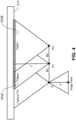
- FIG. 2 illustrates an example of an optoelectronic system 200 for collecting three-dimensional data of a scene over a minimum and maximum distance and for implementing the methods described here.
- the system 200 includes multiple illumination modules 202A, 202B, each of which is operable to generate a respective light pattern 203A, 203B having a respective period T1, T2.
- the system includes an imaging module 204 operable to collect a scene-reflected portion of each of the light patterns and further operable to convert each collected portion into a signal set, wherein each scene-reflected portion is characterized by ambiguity values (i.e., a set of possible disparity vales) and a minimum disparity value, and wherein each signal set corresponds to a respective one of the light patterns.
- ambiguity values i.e., a set of possible disparity vales
- the system 200 includes a non-transitory computer-readable 206 medium (e.g., ROM other memory) comprising instructions stored thereon that, when executed by a processor 208, cause the processor to perform operations for determining candidate three-dimensional data sets, wherein each candidate three-dimensional data set is determined from a respective one of the signal sets.
- the processor 208 is operable to perform further operations for determining three-dimensional data of the scene from the candidate three-dimensional data sets.
- the following paragraphs describe further details according to some implementations that use two illumination modules 202A, 202B, each of which is operable to produce and project a respective light pattern 203A, 203B.
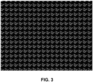
- the patterns 203A, 203B can be for example, regular (e.g., periodic; repetitive) or quasi-periodic. An example of such a light pattern is illustrated in FIG. 3 .
- the first illumination module 202A is operable to produce a periodic first light pattern 203A (e.g., a pattern of dots, stripes or curves) having a period T1.
- the baseline B1 for the first illumination module 202A is the distance from the optical center of the module 202A to the optical center C of the imaging module 204.
- the second illumination module 202B is operable to produce a second periodic light pattern 203B (e.g., of dots, stripes or curves) having a period T2, which differs from the period T1.
- the patterns 203A, 203B may be slightly tilted with respect to the epi-polar line and with respect to each other.
- the baseline B2 for the second illumination module 202B is the distance from the optical center of the module 202B to the optical center C of the imaging module 204.
- Z the distance from the illumination modules 202A, 202B and the imaging module 204 to a surface on which the light patterns are projected.
- the distance value Z also may be referred to as a depth value.
- F represents the focal length of the illumination modules 202A, 202B and the imaging module 204.
- Each of the illumination modules 202A, 202B can be implemented, for example, by a respective regular (e.g., periodic) array of light emitting elements such as laser diodes or vertical cavity surface emitting lasers (VCSELs).
- the baselines B1, B2 for the illumination modules 202A, 202B preferably differ from one another.
- the focusing distances for the illumination modules 202A, 202B can be substantially the same.
- the imaging module 204 can be implemented, for example, as a CMOS or other camera that includes pixels, each of which has a particular pixel size.
- Each light pattern 203A, 203B is used to generate a one parameter-family of solutions for depth.
- each light pattern 203A, 203B is used to generate a respective set of possible disparity values, which correspond to possible values of the depth or distance Z.
- the reference pattern can be obtained, for example, during factory calibration and can be stored in memory coupled to the processor 208.
- n is an unknown integer ⁇ 0 and represents the ambiguity in the value of the disparity.
- the illumination modules 202A, 202B sequentially illuminate a scene 210.
- the modules 202A, 202B can project their respective light patterns onto the scene in short pulses, one after the other.
- the first module 203A briefly projects the first light pattern 203A onto the scene 210, followed by the second module briefly projecting the second light pattern 203B onto the scene.
- the processor 208 can be used to control the ON/OFF operation of the respective illumination modules 202A, 202B.
- the processor 208 is operable, as explained in greater detail below, to process the signal sets generated by the imaging module 204 to determine a disparity value and, thus, a value indicative of the distance (or depth) Z to the scene 210.
- the processor 208 is operable to use the signals detected by the imaging module 204 - based on multiple light patterns 203A, 203B having different respective periods - to narrow down the possible values for "n" and thereby determine the correct disparity value d and the depth Z. This can be accomplished because the depth Z is assumed to be the same regardless of which illumination module 202A, 202B is being used to project the light pattern onto the scene 210.
- the processor 208 is operable to identify an intersection of possible disparity values based on signals detected by the imaging module 204 when the first light pattern 203A is projected onto the scene and of possible disparity values based on signals detected by the imaging module 204 when the second light pattern 203B is projected onto the scene.
- the processor 208 also applies another practical constraint to narrow down the possible values for (n 1 , n 2 ) pairs.
- some of the possible disparity values d correspond to respective depth or distance values Z that are unrealistically small in view of the physical dimensions of the system.
- a minimum distance Z min can be defined and stored, for example, in memory during factory calibration such that values of (n 1 , n 2 ) pairs that correspond to distance values smaller than the minimum distance Z min are ignored or discarded by the processor.
- FIG. 5 illustrates a process flow in accordance with some implementations.
- calibration of the system can be performed, for example, during the manufacture process.
- the imaging module 204 can be placed at a known distance in front of a wall, with the optical axis of the imaging module set perpendicular to the wall.
- a first image is acquired by the imaging module 204 in response to the first illumination module 202A projecting the first light pattern 203A onto the wall while the second illumination module 202B is off (504).
- the first image can be saved as a first reference image in memory associated with the processor 208 (506).
- a second image is acquired by the imaging module 204 in response to the second illumination module 202B projecting the second light pattern 203B onto the wall while the first illumination module 202A is off (508).
- the second image can be saved as a second reference image in memory associated with the processor 208 (510).
- the imaging module 204 captures images of the scene using, sequentially, the first and second illumination modules 202A, 202B (512).
- the imaging module 204 acquires and stores a first image of the scene while the first illumination module 202A projects the first light pattern 203A onto the scene (514) and acquires and stores a second image of the scene while the second illumination module 202B projects the second light pattern 203B onto the scene (516).
- the second illumination module 202B is off (i.e., the second light pattern 203B is not projected onto the scene)
- the first illumination module 202A is off (i.e., the first light pattern 203A is not projected onto the scene).
- the imaging module should move during the interval when the two images are acquired.
- the processor 208 computes the depth Z based on signals representing the acquired images (518).
- the processor 208 compares the first image acquired to the first reference image (acquired during calibration) and computes a first set of possible disparity values based on the comparison (520). This first set of possible values corresponds to the set of values that n 1 can take.
- the processor 208 also compares the second image to the second reference image (acquired during calibration) and computes a second set of possible disparity values based on the comparison (522). This second set of possible values corresponds to the set of values than n 2 can take.
- the processor 208 then computes the intersection of the first and second sets of possible disparity values so as to narrow down the possible disparity values that correspond to the true disparity value (524).
- the processor 208 then eliminates disparity values that are too large (corresponding to Z values that are too small) to derive a final depth value Z (526).
- the processor 208 eliminates, for example, disparity values corresponding to respective distance values Z that are unrealistically small (i.e., ⁇ Z min ) in view of the physical dimensions of the system.
- values of (n 1 , n 2 ) pairs that correspond to distance or depth values smaller than the minimum distance Z min are ignored.
- the (n 1 , n 2 ) pair that corresponds to the smallest depth value equal to, or greater than, Z min is assumed to be the true depth value Z.
- the foregoing steps can be repeated as desired so as to derive disparity (and depth) data for multiple points in the scene.
- the value of Z min can be stored, for example, in memory associated with the processor 208 during system calibration.
- the process by which the processor 208 determines the (n 1 , n 2 ) pair that corresponds to the true disparity also can be expressed as follows.
- the correct value of n 1 can be found by testing possible integer values of n 1 in the range from ceil(-a/b) to (n 1 ) max , where ceil(-a/b) is the ceiling function, which maps a/b to the smallest integer greater than or equal to a/b.
- ceil(-a/b) is the ceiling function, which maps a/b to the smallest integer greater than or equal to a/b.
- each illumination module can project a periodic light pattern having a respective period that differs from the light pattern projected by the other illumination patterns.
- the system may include a single imaging module 204.
- the system can be used as a structured light system in which distortions in the collected pattern(s) correlate with depth. Such techniques can be useful, for example, for low-light and low-texture objects or scenes.
- the system 200 includes multiple imaging modules 204A, 204B, which allows stereoscopic images to be acquired and processed to produce three-dimensional depth information.
- two (or more) imagers are spatially separated by a baseline distance. Depth information can be extracted from the measured disparity between matched pixels in each image, and the focal length of the imagers.
- an object or scene may possess either high-and low-texture or high and low-light regions, where combinations of both stereoscopic and structured-light image capture are useful for generating depth information of the entire scene.
- the illumination modules 202A, 202B may be operable to produce light patterns in the visible range, in the infra-red (IR) range and/or the ultra-violet (UV) range.
- IR infra-red
- UV ultra-violet
- the systems and methods described above for creating and projecting light and determining disparity values can be used, for example, in association with various imaging systems, such as three-dimensional imaging and video systems.
- light projection systems as described above, or modules incorporating such light projection systems can be integrated into a wide range of host devices such as smartphones, laptops, wearable devices and other computing devices that may have with networking capability, as well as automobiles.
- the host devices may include processors and other electronic components, and other supplemental modules configured to collect data, such as cameras, time-of-flight imagers. Other supplemental modules may be included such as ambient lighting, display screens, automotive headlamps, and the like.
- the host devices may further include nonvolatile memory where instructions for operating the optoelectronic modules, and in some instances the supplemental modules, are stored.
- Modules incorporating light projection system as described above can, in some instances, obtain more accurate data than other techniques.
- functions performed by the host device based on signals generated by the light projection system can be performed more accurately, thereby conferring substantial advantages to the smartphone or other host device.
- Embodiments of the subject matter described in this specification can be implemented as one or more computer program products, i.e., one or more modules of computer program instructions encoded on a computer readable medium for execution by, or to control the operation of, data processing apparatus.
- the computer readable medium can be a non-transitory machine-readable storage device, a machine-readable storage substrate, a memory device, a composition of matter effecting a machine-readable propagated signal, or a combination of one or more of them.
- data processing apparatus and “computer” encompasses all apparatus, devices, and machines for processing data, including by way of example a programmable processor, a computer, or multiple processors or computers.
- the apparatus can include, in addition to hardware, code that creates an execution environment for the computer program in question, e.g., code that constitutes processor firmware, a protocol stack, a database management system, an operating system, or a combination of one or more of them.
- a computer program (also known as a program, software, software application, script, or code) can be written in any form of programming language, including compiled or interpreted languages, and it can be deployed in any form, including as a stand alone program or as a module, component, subroutine, or other unit suitable for use in a computing environment.
- a computer program does not necessarily correspond to a file in a file system.
- a program can be stored in a portion of a file that holds other programs or data (e.g., one or more scripts stored in a markup language document), in a single file dedicated to the program in question, or in multiple coordinated files (e.g., files that store one or more modules, sub programs, or portions of code).
- a computer program can be deployed to be executed on one computer or on multiple computers that are located at one site or distributed across multiple sites and interconnected by a communication network.
- the processes and logic flows described in this specification can be performed by one or more programmable processors executing one or more computer programs to perform functions by operating on input data and generating output.
- the processes and logic flows can also be performed by, and apparatus can also be implemented as, special purpose logic circuitry, e.g., an FPGA (field programmable gate array) or an ASIC (application specific integrated circuit).
- processors suitable for the execution of a computer program include, by way of example, both general and special purpose microprocessors, and any one or more processors of any kind of digital computer.
- a processor will receive instructions and data from a read only memory or a random access memory or both.
- the essential elements of a computer are a processor for performing instructions and one or more memory devices for storing instructions and data.
- a computer will also include, or be operatively coupled to receive data from or transfer data to, or both, one or more mass storage devices for storing data, e.g., magnetic, magneto optical disks, or optical disks.
- mass storage devices for storing data, e.g., magnetic, magneto optical disks, or optical disks.
- a computer need not have such devices.
- a computer can be embedded in another device, e.g., a mobile computing device such as a smartphone, a tablet, a personal data assistant (PDA), a notebook computer or other device with networking capability.
- Computer readable media suitable for storing computer program instructions and data include all forms of non volatile memory, media and memory devices, including by way of example semiconductor memory devices, e.g., EPROM, EEPROM, and flash memory devices; magnetic disks, e.g., internal hard disks or removable disks; magneto optical disks; and CD ROM and DVD-ROM disks.
- the processor and the memory can be supplemented by, or incorporated in, special purpose logic circuitry.
Landscapes
- Engineering & Computer Science (AREA)
- Physics & Mathematics (AREA)
- Computer Vision & Pattern Recognition (AREA)
- General Physics & Mathematics (AREA)
- Theoretical Computer Science (AREA)
- Optics & Photonics (AREA)
- Multimedia (AREA)
- Signal Processing (AREA)
- Image Processing (AREA)
- Measurement Of Optical Distance (AREA)
- Length Measuring Devices By Optical Means (AREA)
Claims (15)
- Procédé de collecte, sur une distance minimale et maximale, de données tridimensionnelles d'une scène (210) en utilisant un système optoélectronique (200), la distance minimale correspondant à une plus petite distance réaliste dictée par une ou plusieurs dimensions physiques du système optoélectronique (200), le procédé comprenant :l'éclairage séquentiel de la scène (210) avec une pluralité de motifs lumineux (203A, 203B), où chaque motif lumineux (203A, 203B) a une période respective différente, T ;la collecte séquentielle d'une partie réfléchie par la scène de chacun des motifs lumineux et la conversion de chaque partie collectée en un ensemble de signaux respectifs, où chaque partie réfléchie par la scène est caractérisée par une pluralité respective de valeurs de disparité possibles, d, chaque valeur de disparité possible, d, correspondant à une valeur possible de profondeur ou de distance (Z) dans laquelle chaque valeur de disparité possible, d, est calculée comme un multiple inconnu de la période, T, par :
 où d0 est une valeur de disparité minimale, et n représente une pluralité de valeurs d'ambiguïté, où chaque ensemble de signaux correspond à un respectif des motifs lumineux (203A, 203B) ; etl'élimination de valeurs de disparité correspondant à des distances inférieures à la distance minimale, etla détermination de données tridimensionnelles de la scène (210) à partir des ensembles de signaux, la détermination des données tridimensionnelles de la scène (210) comprenant l'identification d'une intersection de valeurs de disparité possibles pour la pluralité de motifs lumineux (203A, 203B).
 - Procédé selon la revendication 1, dans lequel l'éclairage séquentiel de la scène (210) avec une pluralité de motifs lumineux (203A, 203B) comprend la génération de chaque motif lumineux (203A, 203B) à partir d'un module d'éclairage respectif (202A, 202B), et la collecte séquentielle de la partie réfléchie par la scène de chacun des motifs lumineux (203A, 203B) comprend la collecte des parties réfléchies par la scène avec un module d'imagerie (204, 204A, 204B) dans lequel le module d'imagerie (204, 204A, 204B) a une pluralité de pixels.
- Procédé selon la revendication 2, dans lequel les modules d'éclairage (202A, 202B) ont différentes lignes de base respectives (B, B2), et les modules d'éclairage (202A, 202B) ont des distances de focalisation sensiblement égales et le module d'imagerie (204, 204A, 204B) a une distance d'imagerie ; et, en option
dans lequel la distance d'imagerie est sensiblement égale à une distance de focalisation individuelle. - Procédé selon la revendication 1, dans lequel les périodes sont sensiblement différentes les unes des autres, et les valeurs de disparité minimales sont différentes les unes des autres.
- Procédé selon la revendication 1, dans lequel chaque pluralité de valeurs d'ambiguïté est caractérisée par une valeur maximale liée à la distance minimale, et une valeur minimale sensiblement égale à zéro.
- Procédé selon la revendication 1, dans lequel les valeurs de disparité possibles sont en outre dérivées de :a) la ligne de base (B1, B2) et la distance de focalisation du module d'éclairage correspondant (202A, 202B),b) la distance d'imagerie du module d'imagerie (204, 204A, 204B), etc) la taille des pixels.
- Procédé selon la revendication 6, dans lequel la détermination de données tridimensionnelles de la scène (210) comprend la détermination d'une pluralité de constantes de système optoélectronique ; et, éventuellement,
dans lequel la détermination de données tridimensionnelles de la scène comprend l'utilisation d'au moins une partie des constantes de système optoélectronique pour sélectionner une valeur d'ambiguïté parmi la pluralité de valeurs d'ambiguïté pour chaque motif lumineux correspondant (203A, 203B). - Procédé selon la revendication 7, comprenant en outre l'utilisation d'une fonction de plafond pour sélectionner une valeur d'ambiguïté parmi la pluralité de valeurs d'ambiguïté pour au moins un motif lumineux correspondant (203A, 203B), et, en option,
comprenant la sélection d'une valeur de disparité pour chaque motif lumineux correspondant (203A, 203B) dans la collection correspondante de valeurs de disparité possibles en utilisant ladite une valeur d'ambiguïté sélectionnée correspondant au même motif lumineux (203A, 203B) et la valeur de disparité minimale correspondant au même motif lumineux (203A, 203B). - Système optoélectronique (200) pour collecter des données tridimensionnelles d'une scène (210) sur une distance minimale et maximale, la distance minimale correspondant à une plus petite distance réaliste dictée par une ou plusieurs dimensions physiques du système optoélectronique (200), le système (200) comprenant :une pluralité de modules d'éclairage (202A, 202B), où chaque module d'éclairage (202A, 202B) est conçu pour générer un motif lumineux respectif (203A, 203B) ayant une période respective différente, T ;un module d'imagerie (204, 204A, 204B) conçu pour collecter une partie réfléchie par la scène de chacun des motifs lumineux (203A, 203B) et étant en outre conçu pour convertir chaque partie collectée en un ensemble de signaux respectifs, dans lequel chaque partie réfléchie par la scène est caractérisée par une pluralité respective de valeurs de disparité possibles, d, chaque valeur de disparité possible, d, correspondant à une valeur possible de profondeur ou de distance (Z) dans laquelle chaque valeur de disparité possible, d, est calculée comme un multiple inconnu de la période, T, par :
 où d0 est une valeur de disparité minimale, et n représente une pluralité de valeurs d'ambiguïté, où chaque ensemble de signaux correspond à un respectif des motifs lumineux (203A, 203B) ;un processeur (208) ; etun support lisible par ordinateur non transitoire (206) comprenant des instructions stockées sur celui-ci qui, lorsqu'elles sont exécutées par le processeur (208), amènent le processeur (208) à effectuer des opérations pour déterminer des données tridimensionnelles de la scène (210) à partir des ensembles de signaux, la détermination de données tridimensionnelles de la scène (210) comprenant l'identification d'une intersection de valeurs de disparité possibles pour la pluralité de motifs lumineux (203A, 203B), et à effectuer d'autres opérations comprenant l'élimination de valeurs de disparité correspondant à des distances inférieures à la distance minimale.
 - Système optoélectronique (200) selon la revendication 9, dans lequel le module d'imagerie (204, 204A, 204B) comprend une pluralité de pixels.
- Système optoélectronique (200) selon la revendication 9, dans lequel chaque module d'éclairage (202A, 202B) est caractérisé par une ligne de base (B1, B2), et les lignes de base (B1, B2) sont différentes l'une de l'autre ; et/oudans lequel chaque module d'éclairage (202A, 202B) a une distance de focalisation, et les distances de focalisation sont sensiblement égales ; et/oudans lequel le module d'imagerie (204, 204A, 204B) a une distance d'imagerie, et la distance d'imagerie est sensiblement égale à n'importe laquelle des distances de focalisation.
- Système optoélectronique (200) selon la revendication 11, dans lequel les périodes sont sensiblement différentes les unes des autres, et les valeurs de disparité minimales sont sensiblement différentes les unes des autres ; et, en option
dans lequel chaque pluralité de valeurs d'ambiguïté est caractérisée par une valeur maximale liée à la distance minimale, et une valeur minimale sensiblement égale à zéro. - Système optoélectronique (200) selon la revendication 9, dans lequel le support lisible par ordinateur non transitoire (206) comprend des instructions stockées sur celui-ci qui, lorsqu'elles sont exécutées par le processeur (208), amènent le processeur (208) à effectuer une autre opération consistant à dériver les valeurs de disparité possibles en plus à partir de :a) la ligne de base (B1, B2) et la distance de focalisation du module d'éclairage correspondant (202A, 202B),b) la distance d'imagerie du module d'imagerie (204, 204A, 204B), etc) la taille des pixels.
- Système optoélectronique (200) selon l'une quelconque des revendications 9 à 13, dans lequel chacun des modules d'éclairage (202A, 202B) comprend un réseau périodique respectif d'éléments émetteurs de lumière.
- Dispositif hôte comprenant un système optoélectronique (200) selon l'une quelconque des revendications 9 à 14, dans lequel le dispositif hôte est conçu pour utiliser les données tridimensionnelles de la scène (210) déterminées par le système optoélectronique (200) pour une ou plusieurs fonctions exécutées par le dispositif hôte.
Applications Claiming Priority (2)
| Application Number | Priority Date | Filing Date | Title |
|---|---|---|---|
| US201762563880P | 2017-09-27 | 2017-09-27 | |
| PCT/SG2018/050487 WO2019066724A1 (fr) | 2017-09-27 | 2018-09-25 | Systèmes de projection de lumière |
Publications (3)
| Publication Number | Publication Date |
|---|---|
| EP3688407A1 EP3688407A1 (fr) | 2020-08-05 |
| EP3688407A4 EP3688407A4 (fr) | 2021-06-02 |
| EP3688407B1 true EP3688407B1 (fr) | 2024-07-31 |
Family
ID=65903478
Family Applications (1)
| Application Number | Title | Priority Date | Filing Date |
|---|---|---|---|
| EP18862388.8A Active EP3688407B1 (fr) | 2017-09-27 | 2018-09-25 | Systèmes de projection de lumière |
Country Status (4)
| Country | Link |
|---|---|
| US (1) | US20200320725A1 (fr) |
| EP (1) | EP3688407B1 (fr) |
| CN (1) | CN111373222A (fr) |
| WO (1) | WO2019066724A1 (fr) |
Families Citing this family (5)
| Publication number | Priority date | Publication date | Assignee | Title |
|---|---|---|---|---|
| CN112925351B (zh) * | 2019-12-06 | 2022-08-02 | 杭州萤石软件有限公司 | 一种视觉机器光源控制方法、装置 |
| CN113063371B (zh) * | 2021-03-23 | 2021-09-21 | 广东工业大学 | 面向正弦条纹的非线性自矫正结构光三维测量方法及系统 |
| US12333751B2 (en) * | 2022-01-19 | 2025-06-17 | Ford Global Technologies, Llc | Object detection |
| KR20240058414A (ko) * | 2022-10-26 | 2024-05-03 | 현대모비스 주식회사 | 노면 입체 감지 가능한 램프 시스템 |
| FR3155893B1 (fr) * | 2023-11-28 | 2026-01-02 | Insidix | Dispostif de mesure topographique et procédé de mesure topographique |
Family Cites Families (10)
| Publication number | Priority date | Publication date | Assignee | Title |
|---|---|---|---|---|
| DE4007500A1 (de) * | 1990-03-09 | 1991-09-12 | Zeiss Carl Fa | Verfahren und vorrichtung zur beruehrungslosen vermessung von objektoberflaechen |
| JP2001159510A (ja) * | 1999-12-01 | 2001-06-12 | Matsushita Electric Ind Co Ltd | 三次元形状計測方法及びその装置 |
| US8059280B2 (en) | 2008-01-31 | 2011-11-15 | Cyberoptics Corporation | Method for three-dimensional imaging using multi-phase structured light |
| KR101190122B1 (ko) | 2008-10-13 | 2012-10-11 | 주식회사 고영테크놀러지 | 다중파장을 이용한 3차원형상 측정장치 및 측정방법 |
| TWI546518B (zh) * | 2012-04-20 | 2016-08-21 | 德律科技股份有限公司 | 三維量測系統與三維量測方法 |
| GB201222361D0 (en) * | 2012-12-12 | 2013-01-23 | Univ Birmingham | Surface geometry imaging |
| US9769461B2 (en) * | 2013-07-16 | 2017-09-19 | Texas Instruments Incorporated | Adaptive structured light patterns |
| CN104182968B (zh) * | 2014-08-05 | 2017-03-15 | 西北工业大学 | 宽基线多阵列光学探测系统模糊动目标分割方法 |
| US20160335492A1 (en) * | 2015-05-15 | 2016-11-17 | Everready Precision Ind. Corp. | Optical apparatus and lighting device thereof |
| CN107063128A (zh) * | 2016-04-29 | 2017-08-18 | 华南师范大学 | 一种双频相移三维测量方法及系统 |
-
2018
- 2018-09-25 WO PCT/SG2018/050487 patent/WO2019066724A1/fr not_active Ceased
- 2018-09-25 EP EP18862388.8A patent/EP3688407B1/fr active Active
- 2018-09-25 CN CN201880074528.XA patent/CN111373222A/zh active Pending
- 2018-09-25 US US16/650,120 patent/US20200320725A1/en not_active Abandoned
Also Published As
| Publication number | Publication date |
|---|---|
| US20200320725A1 (en) | 2020-10-08 |
| EP3688407A1 (fr) | 2020-08-05 |
| WO2019066724A1 (fr) | 2019-04-04 |
| EP3688407A4 (fr) | 2021-06-02 |
| CN111373222A (zh) | 2020-07-03 |
Similar Documents
| Publication | Publication Date | Title |
|---|---|---|
| EP3688407B1 (fr) | Systèmes de projection de lumière | |
| US8718326B2 (en) | System and method for extracting three-dimensional coordinates | |
| US10698308B2 (en) | Ranging method, automatic focusing method and device | |
| US20100315490A1 (en) | Apparatus and method for generating depth information | |
| US10648789B2 (en) | Method for monitoring linear dimensions of three-dimensional objects | |
| US11803982B2 (en) | Image processing device and three-dimensional measuring system | |
| CN106875435B (zh) | 获取深度图像的方法及系统 | |
| CN107463659B (zh) | 物体搜索方法及其装置 | |
| JP7078172B2 (ja) | 画像処理装置及び3次元計測システム | |
| US10713810B2 (en) | Information processing apparatus, method of controlling information processing apparatus, and storage medium | |
| JPWO2011125937A1 (ja) | キャリブレーションデータ選択装置、選択方法、及び選択プログラム、並びに三次元位置測定装置 | |
| US9721348B2 (en) | Apparatus and method for raw-cost calculation using adaptive window mask | |
| CN110651166B (zh) | 用于收集三维数据的光电装置 | |
| JP2016081088A (ja) | 画像処理装置、画像処理方法及びプログラム | |
| KR101706627B1 (ko) | 이배율 스테레오 영상을 이용한 거리 측정 장치 및 거리 측정 방법 | |
| CN109741384B (zh) | 深度相机的多距离检测装置及方法 | |
| KR101909528B1 (ko) | 구조광을 이용한 3차원 이미징 방법 및 시스템 | |
| JP6570321B2 (ja) | 情報処理装置、情報処理方法及びプログラム | |
| JPH11183142A (ja) | 三次元画像撮像方法及び三次元画像撮像装置 | |
| JPH11223516A (ja) | 3次元画像撮像装置 | |
| JP2002206919A (ja) | 3次元形状計測装置および3次元形状計測方法 | |
| JP2018063161A (ja) | 情報処理装置、情報処理装置の制御方法及びプログラム | |
| KR101138222B1 (ko) | 전방향 거울 및 차영상 적분 알고리즘을 이용한 구조광 기반 전방향 거리측정 장치 및 방법 | |
| KR101797360B1 (ko) | 초점 정도 비율을 이용하는 깊이 추출 방법 및 깊이 추출 카메라 시스템 |
Legal Events
| Date | Code | Title | Description |
|---|---|---|---|
| STAA | Information on the status of an ep patent application or granted ep patent |
Free format text: STATUS: THE INTERNATIONAL PUBLICATION HAS BEEN MADE |
|
| PUAI | Public reference made under article 153(3) epc to a published international application that has entered the european phase |
Free format text: ORIGINAL CODE: 0009012 |
|
| STAA | Information on the status of an ep patent application or granted ep patent |
Free format text: STATUS: REQUEST FOR EXAMINATION WAS MADE |
|
| 17P | Request for examination filed |
Effective date: 20200324 |
|
| AK | Designated contracting states |
Kind code of ref document: A1 Designated state(s): AL AT BE BG CH CY CZ DE DK EE ES FI FR GB GR HR HU IE IS IT LI LT LU LV MC MK MT NL NO PL PT RO RS SE SI SK SM TR |
|
| AX | Request for extension of the european patent |
Extension state: BA ME |
|
| RIN1 | Information on inventor provided before grant (corrected) |
Inventor name: ROSSI, MARKUS Inventor name: CUTU, FLORIN |
|
| DAV | Request for validation of the european patent (deleted) | ||
| DAX | Request for extension of the european patent (deleted) | ||
| A4 | Supplementary search report drawn up and despatched |
Effective date: 20210503 |
|
| RIC1 | Information provided on ipc code assigned before grant |
Ipc: G01B 11/25 20060101AFI20210426BHEP Ipc: G06T 7/00 20170101ALI20210426BHEP Ipc: G06T 7/521 20170101ALI20210426BHEP Ipc: G06T 7/55 20170101ALI20210426BHEP |
|
| STAA | Information on the status of an ep patent application or granted ep patent |
Free format text: STATUS: EXAMINATION IS IN PROGRESS |
|
| 17Q | First examination report despatched |
Effective date: 20230302 |
|
| P01 | Opt-out of the competence of the unified patent court (upc) registered |
Effective date: 20230613 |
|
| GRAP | Despatch of communication of intention to grant a patent |
Free format text: ORIGINAL CODE: EPIDOSNIGR1 |
|
| STAA | Information on the status of an ep patent application or granted ep patent |
Free format text: STATUS: GRANT OF PATENT IS INTENDED |
|
| INTG | Intention to grant announced |
Effective date: 20240320 |
|
| GRAS | Grant fee paid |
Free format text: ORIGINAL CODE: EPIDOSNIGR3 |
|
| GRAA | (expected) grant |
Free format text: ORIGINAL CODE: 0009210 |
|
| STAA | Information on the status of an ep patent application or granted ep patent |
Free format text: STATUS: THE PATENT HAS BEEN GRANTED |
|
| AK | Designated contracting states |
Kind code of ref document: B1 Designated state(s): AL AT BE BG CH CY CZ DE DK EE ES FI FR GB GR HR HU IE IS IT LI LT LU LV MC MK MT NL NO PL PT RO RS SE SI SK SM TR |
|
| REG | Reference to a national code |
Ref country code: CH Ref legal event code: EP Ref country code: GB Ref legal event code: FG4D |
|
| REG | Reference to a national code |
Ref country code: DE Ref legal event code: R096 Ref document number: 602018072565 Country of ref document: DE |
|
| REG | Reference to a national code |
Ref country code: IE Ref legal event code: FG4D |
|
| REG | Reference to a national code |
Ref country code: LT Ref legal event code: MG9D |
|
| REG | Reference to a national code |
Ref country code: NL Ref legal event code: MP Effective date: 20240731 |
|
| PG25 | Lapsed in a contracting state [announced via postgrant information from national office to epo] |
Ref country code: PT Free format text: LAPSE BECAUSE OF FAILURE TO SUBMIT A TRANSLATION OF THE DESCRIPTION OR TO PAY THE FEE WITHIN THE PRESCRIBED TIME-LIMIT Effective date: 20241202 |
|
| REG | Reference to a national code |
Ref country code: AT Ref legal event code: MK05 Ref document number: 1708838 Country of ref document: AT Kind code of ref document: T Effective date: 20240731 |
|
| PG25 | Lapsed in a contracting state [announced via postgrant information from national office to epo] |
Ref country code: PT Free format text: LAPSE BECAUSE OF FAILURE TO SUBMIT A TRANSLATION OF THE DESCRIPTION OR TO PAY THE FEE WITHIN THE PRESCRIBED TIME-LIMIT Effective date: 20241202 |
|
| PG25 | Lapsed in a contracting state [announced via postgrant information from national office to epo] |
Ref country code: NO Free format text: LAPSE BECAUSE OF FAILURE TO SUBMIT A TRANSLATION OF THE DESCRIPTION OR TO PAY THE FEE WITHIN THE PRESCRIBED TIME-LIMIT Effective date: 20241031 |
|
| PG25 | Lapsed in a contracting state [announced via postgrant information from national office to epo] |
Ref country code: FI Free format text: LAPSE BECAUSE OF FAILURE TO SUBMIT A TRANSLATION OF THE DESCRIPTION OR TO PAY THE FEE WITHIN THE PRESCRIBED TIME-LIMIT Effective date: 20240731 Ref country code: NL Free format text: LAPSE BECAUSE OF FAILURE TO SUBMIT A TRANSLATION OF THE DESCRIPTION OR TO PAY THE FEE WITHIN THE PRESCRIBED TIME-LIMIT Effective date: 20240731 Ref country code: GR Free format text: LAPSE BECAUSE OF FAILURE TO SUBMIT A TRANSLATION OF THE DESCRIPTION OR TO PAY THE FEE WITHIN THE PRESCRIBED TIME-LIMIT Effective date: 20241101 Ref country code: PL Free format text: LAPSE BECAUSE OF FAILURE TO SUBMIT A TRANSLATION OF THE DESCRIPTION OR TO PAY THE FEE WITHIN THE PRESCRIBED TIME-LIMIT Effective date: 20240731 |
|
| PG25 | Lapsed in a contracting state [announced via postgrant information from national office to epo] |
Ref country code: BG Free format text: LAPSE BECAUSE OF FAILURE TO SUBMIT A TRANSLATION OF THE DESCRIPTION OR TO PAY THE FEE WITHIN THE PRESCRIBED TIME-LIMIT Effective date: 20240731 |
|
| PG25 | Lapsed in a contracting state [announced via postgrant information from national office to epo] |
Ref country code: LV Free format text: LAPSE BECAUSE OF FAILURE TO SUBMIT A TRANSLATION OF THE DESCRIPTION OR TO PAY THE FEE WITHIN THE PRESCRIBED TIME-LIMIT Effective date: 20240731 |
|
| PG25 | Lapsed in a contracting state [announced via postgrant information from national office to epo] |
Ref country code: AT Free format text: LAPSE BECAUSE OF FAILURE TO SUBMIT A TRANSLATION OF THE DESCRIPTION OR TO PAY THE FEE WITHIN THE PRESCRIBED TIME-LIMIT Effective date: 20240731 Ref country code: IS Free format text: LAPSE BECAUSE OF FAILURE TO SUBMIT A TRANSLATION OF THE DESCRIPTION OR TO PAY THE FEE WITHIN THE PRESCRIBED TIME-LIMIT Effective date: 20241130 |
|
| PG25 | Lapsed in a contracting state [announced via postgrant information from national office to epo] |
Ref country code: HR Free format text: LAPSE BECAUSE OF FAILURE TO SUBMIT A TRANSLATION OF THE DESCRIPTION OR TO PAY THE FEE WITHIN THE PRESCRIBED TIME-LIMIT Effective date: 20240731 |
|
| PG25 | Lapsed in a contracting state [announced via postgrant information from national office to epo] |
Ref country code: RS Free format text: LAPSE BECAUSE OF FAILURE TO SUBMIT A TRANSLATION OF THE DESCRIPTION OR TO PAY THE FEE WITHIN THE PRESCRIBED TIME-LIMIT Effective date: 20241031 Ref country code: ES Free format text: LAPSE BECAUSE OF FAILURE TO SUBMIT A TRANSLATION OF THE DESCRIPTION OR TO PAY THE FEE WITHIN THE PRESCRIBED TIME-LIMIT Effective date: 20240731 |
|
| PG25 | Lapsed in a contracting state [announced via postgrant information from national office to epo] |
Ref country code: RS Free format text: LAPSE BECAUSE OF FAILURE TO SUBMIT A TRANSLATION OF THE DESCRIPTION OR TO PAY THE FEE WITHIN THE PRESCRIBED TIME-LIMIT Effective date: 20241031 Ref country code: PL Free format text: LAPSE BECAUSE OF FAILURE TO SUBMIT A TRANSLATION OF THE DESCRIPTION OR TO PAY THE FEE WITHIN THE PRESCRIBED TIME-LIMIT Effective date: 20240731 Ref country code: NO Free format text: LAPSE BECAUSE OF FAILURE TO SUBMIT A TRANSLATION OF THE DESCRIPTION OR TO PAY THE FEE WITHIN THE PRESCRIBED TIME-LIMIT Effective date: 20241031 Ref country code: NL Free format text: LAPSE BECAUSE OF FAILURE TO SUBMIT A TRANSLATION OF THE DESCRIPTION OR TO PAY THE FEE WITHIN THE PRESCRIBED TIME-LIMIT Effective date: 20240731 Ref country code: LV Free format text: LAPSE BECAUSE OF FAILURE TO SUBMIT A TRANSLATION OF THE DESCRIPTION OR TO PAY THE FEE WITHIN THE PRESCRIBED TIME-LIMIT Effective date: 20240731 Ref country code: IS Free format text: LAPSE BECAUSE OF FAILURE TO SUBMIT A TRANSLATION OF THE DESCRIPTION OR TO PAY THE FEE WITHIN THE PRESCRIBED TIME-LIMIT Effective date: 20241130 Ref country code: HR Free format text: LAPSE BECAUSE OF FAILURE TO SUBMIT A TRANSLATION OF THE DESCRIPTION OR TO PAY THE FEE WITHIN THE PRESCRIBED TIME-LIMIT Effective date: 20240731 Ref country code: GR Free format text: LAPSE BECAUSE OF FAILURE TO SUBMIT A TRANSLATION OF THE DESCRIPTION OR TO PAY THE FEE WITHIN THE PRESCRIBED TIME-LIMIT Effective date: 20241101 Ref country code: FI Free format text: LAPSE BECAUSE OF FAILURE TO SUBMIT A TRANSLATION OF THE DESCRIPTION OR TO PAY THE FEE WITHIN THE PRESCRIBED TIME-LIMIT Effective date: 20240731 Ref country code: ES Free format text: LAPSE BECAUSE OF FAILURE TO SUBMIT A TRANSLATION OF THE DESCRIPTION OR TO PAY THE FEE WITHIN THE PRESCRIBED TIME-LIMIT Effective date: 20240731 Ref country code: BG Free format text: LAPSE BECAUSE OF FAILURE TO SUBMIT A TRANSLATION OF THE DESCRIPTION OR TO PAY THE FEE WITHIN THE PRESCRIBED TIME-LIMIT Effective date: 20240731 Ref country code: AT Free format text: LAPSE BECAUSE OF FAILURE TO SUBMIT A TRANSLATION OF THE DESCRIPTION OR TO PAY THE FEE WITHIN THE PRESCRIBED TIME-LIMIT Effective date: 20240731 |
|
| PG25 | Lapsed in a contracting state [announced via postgrant information from national office to epo] |
Ref country code: DK Free format text: LAPSE BECAUSE OF FAILURE TO SUBMIT A TRANSLATION OF THE DESCRIPTION OR TO PAY THE FEE WITHIN THE PRESCRIBED TIME-LIMIT Effective date: 20240731 Ref country code: SM Free format text: LAPSE BECAUSE OF FAILURE TO SUBMIT A TRANSLATION OF THE DESCRIPTION OR TO PAY THE FEE WITHIN THE PRESCRIBED TIME-LIMIT Effective date: 20240731 Ref country code: RO Free format text: LAPSE BECAUSE OF FAILURE TO SUBMIT A TRANSLATION OF THE DESCRIPTION OR TO PAY THE FEE WITHIN THE PRESCRIBED TIME-LIMIT Effective date: 20240731 |
|
| PG25 | Lapsed in a contracting state [announced via postgrant information from national office to epo] |
Ref country code: MC Free format text: LAPSE BECAUSE OF FAILURE TO SUBMIT A TRANSLATION OF THE DESCRIPTION OR TO PAY THE FEE WITHIN THE PRESCRIBED TIME-LIMIT Effective date: 20240731 Ref country code: EE Free format text: LAPSE BECAUSE OF FAILURE TO SUBMIT A TRANSLATION OF THE DESCRIPTION OR TO PAY THE FEE WITHIN THE PRESCRIBED TIME-LIMIT Effective date: 20240731 |
|
| PG25 | Lapsed in a contracting state [announced via postgrant information from national office to epo] |
Ref country code: CZ Free format text: LAPSE BECAUSE OF FAILURE TO SUBMIT A TRANSLATION OF THE DESCRIPTION OR TO PAY THE FEE WITHIN THE PRESCRIBED TIME-LIMIT Effective date: 20240731 |
|
| PG25 | Lapsed in a contracting state [announced via postgrant information from national office to epo] |
Ref country code: IT Free format text: LAPSE BECAUSE OF FAILURE TO SUBMIT A TRANSLATION OF THE DESCRIPTION OR TO PAY THE FEE WITHIN THE PRESCRIBED TIME-LIMIT Effective date: 20240731 Ref country code: SK Free format text: LAPSE BECAUSE OF FAILURE TO SUBMIT A TRANSLATION OF THE DESCRIPTION OR TO PAY THE FEE WITHIN THE PRESCRIBED TIME-LIMIT Effective date: 20240731 |
|
| REG | Reference to a national code |
Ref country code: CH Ref legal event code: PL |
|
| REG | Reference to a national code |
Ref country code: DE Ref legal event code: R097 Ref document number: 602018072565 Country of ref document: DE |
|
| PG25 | Lapsed in a contracting state [announced via postgrant information from national office to epo] |
Ref country code: LU Free format text: LAPSE BECAUSE OF NON-PAYMENT OF DUE FEES Effective date: 20240925 |
|
| PLBE | No opposition filed within time limit |
Free format text: ORIGINAL CODE: 0009261 |
|
| STAA | Information on the status of an ep patent application or granted ep patent |
Free format text: STATUS: NO OPPOSITION FILED WITHIN TIME LIMIT |
|
| GBPC | Gb: european patent ceased through non-payment of renewal fee |
Effective date: 20241031 |
|
| 26N | No opposition filed |
Effective date: 20250501 |
|
| PG25 | Lapsed in a contracting state [announced via postgrant information from national office to epo] |
Ref country code: GB Free format text: LAPSE BECAUSE OF NON-PAYMENT OF DUE FEES Effective date: 20241031 |
|
| REG | Reference to a national code |
Ref country code: BE Ref legal event code: MM Effective date: 20240930 |
|
| PG25 | Lapsed in a contracting state [announced via postgrant information from national office to epo] |
Ref country code: BE Free format text: LAPSE BECAUSE OF NON-PAYMENT OF DUE FEES Effective date: 20240930 |
|
| PG25 | Lapsed in a contracting state [announced via postgrant information from national office to epo] |
Ref country code: CH Free format text: LAPSE BECAUSE OF NON-PAYMENT OF DUE FEES Effective date: 20240930 |
|
| PG25 | Lapsed in a contracting state [announced via postgrant information from national office to epo] |
Ref country code: IE Free format text: LAPSE BECAUSE OF NON-PAYMENT OF DUE FEES Effective date: 20240925 |
|
| PG25 | Lapsed in a contracting state [announced via postgrant information from national office to epo] |
Ref country code: SE Free format text: LAPSE BECAUSE OF FAILURE TO SUBMIT A TRANSLATION OF THE DESCRIPTION OR TO PAY THE FEE WITHIN THE PRESCRIBED TIME-LIMIT Effective date: 20240731 |
|
| PGFP | Annual fee paid to national office [announced via postgrant information from national office to epo] |
Ref country code: DE Payment date: 20250919 Year of fee payment: 8 |
|
| PGFP | Annual fee paid to national office [announced via postgrant information from national office to epo] |
Ref country code: FR Payment date: 20250922 Year of fee payment: 8 |
|
| PG25 | Lapsed in a contracting state [announced via postgrant information from national office to epo] |
Ref country code: CY Free format text: LAPSE BECAUSE OF FAILURE TO SUBMIT A TRANSLATION OF THE DESCRIPTION OR TO PAY THE FEE WITHIN THE PRESCRIBED TIME-LIMIT; INVALID AB INITIO Effective date: 20180925 |
|
| PG25 | Lapsed in a contracting state [announced via postgrant information from national office to epo] |
Ref country code: HU Free format text: LAPSE BECAUSE OF FAILURE TO SUBMIT A TRANSLATION OF THE DESCRIPTION OR TO PAY THE FEE WITHIN THE PRESCRIBED TIME-LIMIT; INVALID AB INITIO Effective date: 20180925 |
|
| REG | Reference to a national code |
Ref country code: DE Ref legal event code: R081 Ref document number: 602018072565 Country of ref document: DE Owner name: AMS-OSRAM ASIA PACIFIC PTE. LTD., SG Free format text: FORMER OWNER: AMS SENSORS SINGAPORE PTE. LTD., SINGAPORE, SG |