EP3689575A1 - Organe de commande de machine de moulage par injection et machine de moulage par injection - Google Patents
Organe de commande de machine de moulage par injection et machine de moulage par injection Download PDFInfo
- Publication number
- EP3689575A1 EP3689575A1 EP20153277.7A EP20153277A EP3689575A1 EP 3689575 A1 EP3689575 A1 EP 3689575A1 EP 20153277 A EP20153277 A EP 20153277A EP 3689575 A1 EP3689575 A1 EP 3689575A1
- Authority
- EP
- European Patent Office
- Prior art keywords
- button
- history
- setting conditions
- screen
- injection molding
- Prior art date
- Legal status (The legal status is an assumption and is not a legal conclusion. Google has not performed a legal analysis and makes no representation as to the accuracy of the status listed.)
- Granted
Links
Images





Classifications
-
- B—PERFORMING OPERATIONS; TRANSPORTING
- B29—WORKING OF PLASTICS; WORKING OF SUBSTANCES IN A PLASTIC STATE IN GENERAL
- B29C—SHAPING OR JOINING OF PLASTICS; SHAPING OF MATERIAL IN A PLASTIC STATE, NOT OTHERWISE PROVIDED FOR; AFTER-TREATMENT OF THE SHAPED PRODUCTS, e.g. REPAIRING
- B29C45/00—Injection moulding, i.e. forcing the required volume of moulding material through a nozzle into a closed mould; Apparatus therefor
- B29C45/17—Component parts, details or accessories; Auxiliary operations
- B29C45/76—Measuring, controlling or regulating
- B29C45/766—Measuring, controlling or regulating the setting or resetting of moulding conditions, e.g. before starting a cycle
-
- B—PERFORMING OPERATIONS; TRANSPORTING
- B29—WORKING OF PLASTICS; WORKING OF SUBSTANCES IN A PLASTIC STATE IN GENERAL
- B29C—SHAPING OR JOINING OF PLASTICS; SHAPING OF MATERIAL IN A PLASTIC STATE, NOT OTHERWISE PROVIDED FOR; AFTER-TREATMENT OF THE SHAPED PRODUCTS, e.g. REPAIRING
- B29C45/00—Injection moulding, i.e. forcing the required volume of moulding material through a nozzle into a closed mould; Apparatus therefor
- B29C45/17—Component parts, details or accessories; Auxiliary operations
- B29C45/1774—Display units or mountings therefor; Switch cabinets
-
- B—PERFORMING OPERATIONS; TRANSPORTING
- B29—WORKING OF PLASTICS; WORKING OF SUBSTANCES IN A PLASTIC STATE IN GENERAL
- B29C—SHAPING OR JOINING OF PLASTICS; SHAPING OF MATERIAL IN A PLASTIC STATE, NOT OTHERWISE PROVIDED FOR; AFTER-TREATMENT OF THE SHAPED PRODUCTS, e.g. REPAIRING
- B29C45/00—Injection moulding, i.e. forcing the required volume of moulding material through a nozzle into a closed mould; Apparatus therefor
- B29C45/17—Component parts, details or accessories; Auxiliary operations
- B29C45/76—Measuring, controlling or regulating
-
- B—PERFORMING OPERATIONS; TRANSPORTING
- B29—WORKING OF PLASTICS; WORKING OF SUBSTANCES IN A PLASTIC STATE IN GENERAL
- B29C—SHAPING OR JOINING OF PLASTICS; SHAPING OF MATERIAL IN A PLASTIC STATE, NOT OTHERWISE PROVIDED FOR; AFTER-TREATMENT OF THE SHAPED PRODUCTS, e.g. REPAIRING
- B29C45/00—Injection moulding, i.e. forcing the required volume of moulding material through a nozzle into a closed mould; Apparatus therefor
- B29C45/17—Component parts, details or accessories; Auxiliary operations
- B29C45/76—Measuring, controlling or regulating
- B29C45/762—Measuring, controlling or regulating the sequence of operations of an injection cycle
-
- B—PERFORMING OPERATIONS; TRANSPORTING
- B29—WORKING OF PLASTICS; WORKING OF SUBSTANCES IN A PLASTIC STATE IN GENERAL
- B29C—SHAPING OR JOINING OF PLASTICS; SHAPING OF MATERIAL IN A PLASTIC STATE, NOT OTHERWISE PROVIDED FOR; AFTER-TREATMENT OF THE SHAPED PRODUCTS, e.g. REPAIRING
- B29C45/00—Injection moulding, i.e. forcing the required volume of moulding material through a nozzle into a closed mould; Apparatus therefor
- B29C45/17—Component parts, details or accessories; Auxiliary operations
- B29C45/76—Measuring, controlling or regulating
- B29C2045/7606—Controlling or regulating the display unit
Definitions
- a setting history of the setting conditions saved in the past is displayed on the screen of the display unit, and an operator memorizes the setting conditions described therein, takes notes, or the like. Then, the operator inputs the setting conditions after returning to a screen for inputting the setting conditions .
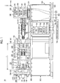
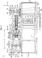
- the injection molding machine 10 includes a mold clamping unit 100, an ejector unit 200, an injection unit 300, a movement unit 400, a controller 700, and a frame 900.
- the frame 900 includes a mold clamping unit frame 910 and an injection unit frame 920.
- the mold clamping unit frame 910 and the injection unit frame 920 are respectively installed on a floor 2 through a leveling adjuster 930.
- the controller 700 is disposed in the internal space of the injection unit frame 920.
- each component of the injection molding machine 10 will be described.
- the mold clamping unit 100 is, for example, the horizontal type, and the mold opening and closing direction is the horizontal direction.
- the mold clamping unit 100 includes a stationary platen 110, a movable platen 120, a toggle support 130, a tie bar 140, a toggle mechanism 150, a mold clamping motor 160, a motion conversion mechanism 170, and a mold space adjustment mechanism 180.
- the movable platen 120 is disposed so as to be movable in the mold opening and closing direction with respect to the mold clamping unit frame 910.
- a guide 101 which guides the movable platen 120 is placed on the mold clamping unit frame 910.
- the movable mold 820 is attached to a surface of the movable platen 120 facing the stationary platen 110.
- the movable platen 120 moves forward or rearward with respect to the stationary platen 110, and thus the mold closing, pressurizing, mold clamping, depressurizing, and mold opening of the mold unit 800 are performed.
- the toggle support 130 is disposed so as to be separated from the stationary platen 110 and is placed on the mold clamping unit frame 910 to be movable in mold opening and closing direction.
- the toggle support 130 may be disposed so as to be movable along a guide which is placed on the mold clamping unit frame 910.
- the guide of the toggle support 130 may be also used as the guide 101 of the movable platen 120.
- Setting conditions are similarly set in the depressurization process and the mold opening process.
- movement speeds or positions (mold opening start position, movement speed switching position, and mold opening completion position) of the crosshead 151 in the depressurization process and the mold opening process are collectively set as a series of setting conditions .
- the mold opening start position, the movement speed switching position, and the mold opening completion position are arranged in this order from the front side to the rear side and represent a start point and an end point of a section where the movement speed is set.
- the movement speed is set for each section.
- the movement speed switching position may be one or more.
- the movement speed switching position may not be set.
- the mold opening start position may be the same as the mold closing completion position.
- the mold opening completion position may be the same as the mold closing start position.
- the controller 700 drives the mold space adjustment motor 183 to rotate the screw nut 182.
- the controller 700 drives the mold space adjustment motor 183 to rotate the screw nut 182.
- the position of the toggle support 130 with respect to the tie bar 140 is adjusted, and the gap L between the stationary platen 110 and the toggle support 130 is adjusted.
- a plurality of mold space adjustment mechanisms may be used in combination.
- the cylinder 310 heats the molding material which is supplied from a supply port 311 to the inner portion of the cylinder 310.
- the molding material includes, for example, a resin.
- the molding material is formed, for example, in a pallet shape and is supplied to the supply port 311 in a solid state.
- the supply port 311 is formed on a rear portion of the cylinder 310.
- a cooler 312 such as a water cooling cylinder is provided on an outer periphery of the rear portion of the cylinder 310.
- a heating unit 313 such as a band heater and the temperature detector 314 are provided on an outer periphery of the cylinder 310 on a front side of the cooler 312.
- the backflow prevention ring 331 When the screw 330 moves forward, the backflow prevention ring 331 is pressed toward the rear side by the pressure of the molding material in the front side of the screw 330 and moves rearward relatively with respect to the screw 330 to a close position (refer to Fig. 2 ) at which a flow path of the molding material is closed. Accordingly, the molding material accumulated in the front side of the screw 330 is prevented from flowing toward the rear side.
- the backflow prevention ring 331 may be any one of a co-rotation type ring which rotates together with the screw 330 or a non-co-rotation type ring which does not rotate together with the screw 330.
- the injection unit 300 may include a drive source which causes the backflow prevention ring 331 to move forward or rearward with respect to the screw 330 between the open position and the close position.
- the plasticizing motor 340 rotates the screw 330.
- a drive source which rotates the screw 330 is not limited to the plasticizing motor 340 and may be, for example, a hydraulic pump.
- the pressure detector 360 sends a signal indicating a detection result to the controller 700.
- the detection result of the pressure detector 360 is used to control or monitor a pressure received by the screw 330 from the molding material, a back pressure with respect to the screw 330, a pressure applied from the screw 330 to the molding material, or the like.
- the injection unit 300 performs a plasticizing process, a filling process, a holding pressure process, or the like under the control of the controller 700.
- the filling process and the holding pressure process are collectively referred to as an injection process.
- the injection motor 350 may be driven to add a set back pressure with respect to the screw 330.
- the back pressure with respect to the screw 330 is detected using, for example, the pressure detector 360.
- the pressure detector 360 sends a signal indicating a detection result to the controller 700.
- the movement direction (for example, the X-axis negative direction) of the screw 330 during filling is defined as the front side
- the movement direction (for example, the X-axis positive direction) of the screw 330 during plasticizing is defined as the rear side.
- the controller 700 repeats the plasticizing process, the mold closing process, the pressurizing process, the mold clamping process, the filling process, the holding pressure process, the cooling process, the depressurizing process, the mold opening process, the ejection process, and the like to repeatedly manufacture the molding product.
- a series of operations to obtain the molding product for example, an operation from the start of the plasticizing process to the start of the next plasticizing process is also referred to as a "shot” or a "molding cycle”.
- a time required for one shot is also referred to as a "molding cycle time" or "cycle time”.
- the one molding cycle may include a process other than the plasticizing process, the mold closing process, the pressurizing process, the mold clamping process, the filling process, the holding pressure process, the cooling process, the depressurizing process, the mold opening process, and the ejection process.
- a pre-plasticizing suck-back process in which the screw 330 moves rearward to a plasticizing start position set in advance may be performed after the completion of the holding pressure process and before the start of the plasticizing process. It is possible to reduce the pressure of the molding material accumulated in the front side of the screw 330 before the start of the plasticizing process and thus to prevent the abrupt rearward movement of the screw 330 at the start of the plasticizing process .
- the display screen is used for the setting of the injection molding machine 10 or the like.
- a plurality of display screens are provided and displayed by switching or overlapping each other .
- a user operates the operation unit 750 while viewing the display screen displayed on the display unit 760 to perform the setting (including an input of a set value) of the injection molding machine 10 or the like.
- the history button display processing section 728 displays the history button 753 on the button display portion 22 of the display unit 760.
- the history button display processing section 728 reads history button image data stored in the storage medium 702, for example, and inputs the read history button image data to the display unit 760 in order to display the history button 753 on the button display portion 22.
- the history button image data is data representing a symbol corresponding to a function of the history button 753.
- the controller 700 is characterized in that the controller 700 includes the history button display processing section 728 which displays the history button 753 for displaying the history of the setting conditions set in the past on the display screen 20 on which the setting conditions are displayed.
- a numerical value indicating a speed until the screw 330 whose operation is started reaches a position in the input field 30 is input to an input field 32 of the first screen 21a.
- a numeric keypad is displayed by touching the input field 32. Therefore, it is possible to input any value using the numeric keypad.
- a numerical value indicating a time is input to the input field 40 of the second screen 21b. Specifically, a time for maintaining a pressure input in the input field 42 after the V/P switching is input to the input field 40.
- a numeric keypad is displayed by touching the input field 40. Therefore, it is possible to input any value using the numeric keypad.
- a numerical value indicating a pressure for the V/P switching is input to the input field 51 of the third screen 21c.
- a numeric keypad is displayed by touching the input field 51. Therefore, it is possible to input any value using the numeric keypad.
- the switching from the filling process to the holding pressure process is performed regardless of the numerical value input to the first screen 21a.
- the history button 753 is the button for displaying a list of the setting conditions set in the past as the setting history by arranging in a time-series order. The display of the condition setting history to be displayed when the history button 753 is pressed will be described with reference to Fig. 6 .
- condition button display processing section 727 may perform display control in which the setting conditions on the first screen21a are switched or may perform display control, for example, in which the setting conditions before the backward button 751 is pressed once and the setting conditions after the backward button 751 is pressed once are displayed on the first screen 21a at the same time, as shown in Fig. 7 .
- step S3 the controller 700 switches the setting conditions to new setting conditions in a time-series than currently displayed setting condition (step S4). For example, in a case where the forward button 752 is pressed when the setting conditions shown in (E) of Fig. 7 is displayed, the setting conditions shown in (G) of Fig. 7 is switched.
- Fig. 9 is a diagram showing a second example of the screen to be displayed on the display unit included in the injection molding machine according to the embodiment.
- a fourth screen 21d is displayed instead of the first screen 21a to the third screen 21c.
- An item representing the number of shots, an item representing a timepoint when the shot is performed, and a plurality of management items are displayed on the fourth screen 21d.
- the "shot” is a series of operations to obtain the molding product, for example, an operation from the start of the plasticizing process to the start of the next plasticizing process .
- the "management item” is an item for displaying the data used for the management of the molding operation of the injection molding machine 10. For example, a cycle time, a filling time, and a plasticizing time are displayed in the management items on the fourth screen 21d shown in Fig. 9 .
- the plasticizing time is a time for the plasticizing process.
- the plasticizing time is equal to a time from when the plasticizing motor 340 drives the screw 330 to rotate at a set rotating speed and the molding material starts to be fed forward along the spiral grooves of the screw 330 to when the screw 330 moves backward, as the molding material is fed to the front side of the screw 330 and accumulated in the front portion of the cylinder 310, and a predetermined amount of molding material is accumulated in the front side of the screw 330.
- the management item 73 is a button for displaying the plasticizing time on the fourth screen 21d as the data used for the management of the molding operation of the injection molding machine 10.
- the plasticizing time is the time for the plasticizing process.
- management items 71, 72, and 73 are pressed from the six management items 71 to 76 to be displayed on the management item selection screen 70, the management items 71, 72, and 73 are switched, for example, from an outline in white background to an outline in black background.
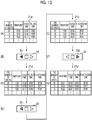
- condition button display processing section 727 may perform display control in which the setting conditions (management items) on the fourth screen 21d are switched or may perform display control, for example, in which the setting conditions (management items) before the backward button 751 is pressed once and the setting conditions (management items) after the backward button 751 is pressed once are displayed on the fourth screen 21d at the same time, as shown in Fig. 12 .
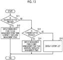
- step S13 the controller 700 switches the management items to new management items in a time-series than currently displayed management items (step S14). For example, in a case where the forward button 752 is pressed when the management item shown in (E) of Fig. 12 is displayed, the management items are switched to the management items shown in (G) of Fig. 12 .
- the controller 700 according to the present embodiment when the type and number of management items are changed using the management item selection screen 70 and then the same management items set in the past are used again, the operator can display the same management items set in the past only by pressing the backward button 751 without changing the type or number of management items using the management item selection screen 70. Therefore, with the controller 700 according to the present embodiment, it is possible to save time and effort to change the type and number of management items again using the management item selection screen 70, and thus to shorten the work time accompanying the change in the type and number of management items and suppress erroneous input.
- a waveform selected in the waveform selection field 60 is displayed on the waveform display screen 80.
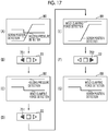
- the waveform display screen 80 shows, for example, "mold clamping force detection” representing the detection result of the tie bar strain detector 141 that detects the strain of the tie bar 140 as a continuous waveform in a time-series, "holding pressure detection” representing the detection result of the pressure detector 360 in the holding pressure process as a continuous waveform in a time-series, and "screw position detection” representing the detection result of the injection motor encoder 351 that detects the screw position as a continuous waveform in a time-series.
- Fig. 18 is a flowchart of switching processing of the waveforms.
- the controller 700 determines whether or not the backward button 751 is pressed in step S21. In a case where the backward button 751 is pressed (Yes in step S21), the controller 700 switches the waveforms to old waveforms in a time-series than currently displayed waveforms (step S22). For example, in a case where the backward button 751 is pressed when the waveforms shown in (C) of Fig. 17 is displayed, the waveforms are switched to the waveforms shown in (E) of Fig. 17 .
- Step S25 the controller 700 determines that the history button 753 is pressed and displays the history display portion 223c (Step S25).
- the condition button display processing section 727 may perform display control in which the setting conditions (waveforms) on the waveform display screen 80 are switched or may perform display control, for example, in which the setting conditions (waveforms) before the backward button 751 is pressed once and the setting conditions (waveforms) after the backward button 751 is pressed once are displayed on the waveform display screen 80 at the same time, as shown in Fig. 17 .
- the controller 700 may be configured to include a history addition section which adds setting conditions of injection molding to the history when the injection molding is performed.
- the history does not include setting conditions which are only displayed without being reflected in the operation of the injection molding machine. Therefore, only the setting conditions used for the molding adjustment can be left as the history. Therefore, it is possible to easily search for only the setting conditions used for the molding adjustment as compared with a case where all the displayed setting conditions are added as the history.
- the controller 700 may be configured to include a molding pass or fail result display portion which displays a pass or fail result of the injection molding in association with the setting conditions of the injection molding when the injection molding is performed.
Landscapes
- Engineering & Computer Science (AREA)
- Manufacturing & Machinery (AREA)
- Mechanical Engineering (AREA)
- Injection Moulding Of Plastics Or The Like (AREA)
Applications Claiming Priority (1)
| Application Number | Priority Date | Filing Date | Title |
|---|---|---|---|
| JP2019016418A JP7195956B2 (ja) | 2019-01-31 | 2019-01-31 | 表示装置、射出成形機の制御装置、及び射出成形機 |
Publications (2)
| Publication Number | Publication Date |
|---|---|
| EP3689575A1 true EP3689575A1 (fr) | 2020-08-05 |
| EP3689575B1 EP3689575B1 (fr) | 2021-05-12 |
Family
ID=69191875
Family Applications (1)
| Application Number | Title | Priority Date | Filing Date |
|---|---|---|---|
| EP20153277.7A Active EP3689575B1 (fr) | 2019-01-31 | 2020-01-23 | Organe de commande de machine de moulage par injection et machine de moulage par injection |
Country Status (3)
| Country | Link |
|---|---|
| EP (1) | EP3689575B1 (fr) |
| JP (1) | JP7195956B2 (fr) |
| CN (2) | CN115256805B (fr) |
Cited By (3)
| Publication number | Priority date | Publication date | Assignee | Title |
|---|---|---|---|---|
| US12350870B2 (en) * | 2021-08-27 | 2025-07-08 | Sumitomo Heavy Industries, Ltd. | Control device of injection molding machine, injection molding machine, and recording medium |
| EP4650143A1 (fr) * | 2024-05-14 | 2025-11-19 | Toyo Innovex Co., Ltd. | Machine de moulage comprenant un dispositif de commande configuré pour amener un dispositif d'affichage à afficher un ecran d'entité d'information de changement |
| EP4717434A1 (fr) * | 2024-09-30 | 2026-04-01 | Toyo Innovex Co., Ltd. | Machine de moulage |
Families Citing this family (5)
| Publication number | Priority date | Publication date | Assignee | Title |
|---|---|---|---|---|
| JP7477419B2 (ja) * | 2020-09-30 | 2024-05-01 | 住友重機械工業株式会社 | 射出成形機 |
| WO2022085580A1 (fr) * | 2020-10-20 | 2022-04-28 | ファナック株式会社 | Dispositif de réglage de conditions de moulage et procédé de réglage de conditions de moulage |
| JP7640016B2 (ja) * | 2021-08-11 | 2025-03-05 | 住友重機械工業株式会社 | 射出成形機の制御装置、射出成形機、及びプログラム |
| CN113843405A (zh) * | 2021-09-23 | 2021-12-28 | 马鞍山市兴隆铸造有限公司 | 一种上下连续式铸造设备 |
| JP7815572B2 (ja) * | 2022-03-30 | 2026-02-18 | 住友重機械工業株式会社 | 射出成形機の表示入力装置、射出成形機の制御装置 |
Citations (8)
| Publication number | Priority date | Publication date | Assignee | Title |
|---|---|---|---|---|
| JPS5654064B2 (fr) | 1974-11-28 | 1981-12-23 | ||
| US5470218A (en) * | 1993-07-07 | 1995-11-28 | Wheaton Inc. | Graphical interface driven injection blow molding apparatus |
| US20040186607A1 (en) * | 2003-01-30 | 2004-09-23 | Toshiba Machine Co., Ltd. | Display device and history collecting system |
| US20060247821A1 (en) * | 2005-04-28 | 2006-11-02 | Toshiba Kikai Kabushiki Kaisha | Control device of injection molding machine |
| EP1717655A1 (fr) * | 2005-04-18 | 2006-11-02 | Fanuc Ltd | Contrôleur d'affichage pour machine de moulage par injection |
| US20110106284A1 (en) * | 2009-11-02 | 2011-05-05 | Mold-Masters (2007) Limited | System for use in performance of injection molding operations |
| US20110160895A1 (en) * | 2009-12-29 | 2011-06-30 | Hong Fu Jin Precision Industry (Shenzhen) Co., Ltd | Injection molding controller, manufacturing method thereof, and injection molding system using the same |
| US20120231103A1 (en) * | 2011-03-11 | 2012-09-13 | Mold-Masters (2007) Limited | Cycle counting system for injection molding assembly |
Family Cites Families (14)
| Publication number | Priority date | Publication date | Assignee | Title |
|---|---|---|---|---|
| JP2673464B2 (ja) | 1990-06-18 | 1997-11-05 | ファナック株式会社 | 成形モニタ装置 |
| JP3519604B2 (ja) * | 1998-05-28 | 2004-04-19 | ファナック株式会社 | 射出成形機における成形条件再生装置 |
| JP2000318012A (ja) * | 1999-05-17 | 2000-11-21 | Japan Steel Works Ltd:The | 射出成形機の成形条件管理方法 |
| JP3752979B2 (ja) * | 2000-08-11 | 2006-03-08 | 宇部興産機械株式会社 | 成形データの記録表示方法 |
| JP4291175B2 (ja) | 2004-02-20 | 2009-07-08 | 住友重機械工業株式会社 | 成形機の管理方法及び管理システム |
| JP4738883B2 (ja) | 2005-04-28 | 2011-08-03 | 東芝機械株式会社 | 射出成形機の制御装置 |
| JP5384053B2 (ja) * | 2008-08-28 | 2014-01-08 | 住友重機械工業株式会社 | 設定画面、射出成形機及び設定画面の表示方法 |
| JP2012056147A (ja) * | 2010-09-07 | 2012-03-22 | Sumitomo Heavy Ind Ltd | 射出成形機 |
| JP2013043336A (ja) * | 2011-08-23 | 2013-03-04 | Meiki Co Ltd | 成形機の表示装置および表示方法 |
| JP5421973B2 (ja) * | 2011-10-24 | 2014-02-19 | 日精樹脂工業株式会社 | 生産機械の表示装置 |
| JP5654064B2 (ja) | 2013-02-13 | 2015-01-14 | ファナック株式会社 | 射出成形機の表示装置および表示方法 |
| JP2015182087A (ja) | 2014-03-20 | 2015-10-22 | 住友重機械工業株式会社 | 射出成形機、および射出成形機の操作画面 |
| JP2018036740A (ja) * | 2016-08-30 | 2018-03-08 | パナソニックIpマネジメント株式会社 | 情報端末装置、稼動情報提供システムおよび稼動情報提供プログラム |
| JP6603260B2 (ja) * | 2017-04-27 | 2019-11-06 | ファナック株式会社 | 数値制御装置 |
-
2019
- 2019-01-31 JP JP2019016418A patent/JP7195956B2/ja active Active
-
2020
- 2020-01-08 CN CN202211005861.XA patent/CN115256805B/zh active Active
- 2020-01-08 CN CN202010016346.6A patent/CN111497129A/zh active Pending
- 2020-01-23 EP EP20153277.7A patent/EP3689575B1/fr active Active
Patent Citations (8)
| Publication number | Priority date | Publication date | Assignee | Title |
|---|---|---|---|---|
| JPS5654064B2 (fr) | 1974-11-28 | 1981-12-23 | ||
| US5470218A (en) * | 1993-07-07 | 1995-11-28 | Wheaton Inc. | Graphical interface driven injection blow molding apparatus |
| US20040186607A1 (en) * | 2003-01-30 | 2004-09-23 | Toshiba Machine Co., Ltd. | Display device and history collecting system |
| EP1717655A1 (fr) * | 2005-04-18 | 2006-11-02 | Fanuc Ltd | Contrôleur d'affichage pour machine de moulage par injection |
| US20060247821A1 (en) * | 2005-04-28 | 2006-11-02 | Toshiba Kikai Kabushiki Kaisha | Control device of injection molding machine |
| US20110106284A1 (en) * | 2009-11-02 | 2011-05-05 | Mold-Masters (2007) Limited | System for use in performance of injection molding operations |
| US20110160895A1 (en) * | 2009-12-29 | 2011-06-30 | Hong Fu Jin Precision Industry (Shenzhen) Co., Ltd | Injection molding controller, manufacturing method thereof, and injection molding system using the same |
| US20120231103A1 (en) * | 2011-03-11 | 2012-09-13 | Mold-Masters (2007) Limited | Cycle counting system for injection molding assembly |
Cited By (3)
| Publication number | Priority date | Publication date | Assignee | Title |
|---|---|---|---|---|
| US12350870B2 (en) * | 2021-08-27 | 2025-07-08 | Sumitomo Heavy Industries, Ltd. | Control device of injection molding machine, injection molding machine, and recording medium |
| EP4650143A1 (fr) * | 2024-05-14 | 2025-11-19 | Toyo Innovex Co., Ltd. | Machine de moulage comprenant un dispositif de commande configuré pour amener un dispositif d'affichage à afficher un ecran d'entité d'information de changement |
| EP4717434A1 (fr) * | 2024-09-30 | 2026-04-01 | Toyo Innovex Co., Ltd. | Machine de moulage |
Also Published As
| Publication number | Publication date |
|---|---|
| EP3689575B1 (fr) | 2021-05-12 |
| CN115256805A (zh) | 2022-11-01 |
| JP7195956B2 (ja) | 2022-12-26 |
| JP2020121547A (ja) | 2020-08-13 |
| CN111497129A (zh) | 2020-08-07 |
| CN115256805B (zh) | 2024-12-10 |
Similar Documents
| Publication | Publication Date | Title |
|---|---|---|
| EP3689575B1 (fr) | Organe de commande de machine de moulage par injection et machine de moulage par injection | |
| EP3546181B1 (fr) | Contrôleur de machine de moulage par injection et machine de moulage par injection | |
| EP3381647B1 (fr) | Machine de moulage par injection et dispositif de traitement d'informations de moulage par injection | |
| EP3858577B1 (fr) | Machine de moulage à injection | |
| EP3546184B1 (fr) | Dispositif de gestion de données de moulage par injection et machine de moulage par injection | |
| JP2013212596A (ja) | 射出成形機 | |
| EP3778183B1 (fr) | Machine de moulage par injection | |
| EP3372376A1 (fr) | Machine de moulage à injection | |
| EP3546176B1 (fr) | Machine de moulage à injection | |
| US12623386B2 (en) | Controller of injection molding machine, injection molding machine, and recording medium | |
| US12420468B2 (en) | Controller of injection molding machine, injection molding machine, and recording medium | |
| US20230173727A1 (en) | Control device for injection molding machine, and control method for injection molding machine | |
| EP3546171B1 (fr) | Machine de moulage à injection | |
| EP3858579B1 (fr) | Machine de moulage à injection | |
| US12623388B2 (en) | Controller of injection molding machine, injection molding machine, and program | |
| US12023833B2 (en) | Display device for injection molding machine | |
| US12036713B2 (en) | Injection molding machine and management device for injection molding | |
| US12583155B2 (en) | Control device for injection molding machine and control method for injection molding machine | |
| US20240131766A1 (en) | Display unit, control device, and injection molding machine | |
| US20240399633A1 (en) | Display device of injection molding machine, and injection molding machine | |
| US20240198566A1 (en) | Display unit of injection molding machine, control device of injection molding machine, and injection molding machine | |
| EP3366449B1 (fr) | Machine de moulage à injection | |
| JP2024126121A (ja) | 射出成形機の制御装置、射出成形機および射出成形機の制御方法 |
Legal Events
| Date | Code | Title | Description |
|---|---|---|---|
| STAA | Information on the status of an ep patent application or granted ep patent |
Free format text: STATUS: EXAMINATION IS IN PROGRESS |
|
| PUAI | Public reference made under article 153(3) epc to a published international application that has entered the european phase |
Free format text: ORIGINAL CODE: 0009012 |
|
| 17P | Request for examination filed |
Effective date: 20200123 |
|
| AK | Designated contracting states |
Kind code of ref document: A1 Designated state(s): AL AT BE BG CH CY CZ DE DK EE ES FI FR GB GR HR HU IE IS IT LI LT LU LV MC MK MT NL NO PL PT RO RS SE SI SK SM TR |
|
| AX | Request for extension of the european patent |
Extension state: BA ME |
|
| GRAP | Despatch of communication of intention to grant a patent |
Free format text: ORIGINAL CODE: EPIDOSNIGR1 |
|
| STAA | Information on the status of an ep patent application or granted ep patent |
Free format text: STATUS: GRANT OF PATENT IS INTENDED |
|
| INTG | Intention to grant announced |
Effective date: 20201209 |
|
| GRAS | Grant fee paid |
Free format text: ORIGINAL CODE: EPIDOSNIGR3 |
|
| GRAA | (expected) grant |
Free format text: ORIGINAL CODE: 0009210 |
|
| STAA | Information on the status of an ep patent application or granted ep patent |
Free format text: STATUS: THE PATENT HAS BEEN GRANTED |
|
| AK | Designated contracting states |
Kind code of ref document: B1 Designated state(s): AL AT BE BG CH CY CZ DE DK EE ES FI FR GB GR HR HU IE IS IT LI LT LU LV MC MK MT NL NO PL PT RO RS SE SI SK SM TR |
|
| REG | Reference to a national code |
Ref country code: GB Ref legal event code: FG4D |
|
| REG | Reference to a national code |
Ref country code: CH Ref legal event code: EP |
|
| REG | Reference to a national code |
Ref country code: DE Ref legal event code: R096 Ref document number: 602020000088 Country of ref document: DE |
|
| REG | Reference to a national code |
Ref country code: IE Ref legal event code: FG4D |
|
| REG | Reference to a national code |
Ref country code: AT Ref legal event code: REF Ref document number: 1391889 Country of ref document: AT Kind code of ref document: T Effective date: 20210615 |
|
| REG | Reference to a national code |
Ref country code: LT Ref legal event code: MG9D |
|
| REG | Reference to a national code |
Ref country code: NL Ref legal event code: MP Effective date: 20210512 |
|
| PG25 | Lapsed in a contracting state [announced via postgrant information from national office to epo] |
Ref country code: BG Free format text: LAPSE BECAUSE OF FAILURE TO SUBMIT A TRANSLATION OF THE DESCRIPTION OR TO PAY THE FEE WITHIN THE PRESCRIBED TIME-LIMIT Effective date: 20210812 Ref country code: FI Free format text: LAPSE BECAUSE OF FAILURE TO SUBMIT A TRANSLATION OF THE DESCRIPTION OR TO PAY THE FEE WITHIN THE PRESCRIBED TIME-LIMIT Effective date: 20210512 Ref country code: HR Free format text: LAPSE BECAUSE OF FAILURE TO SUBMIT A TRANSLATION OF THE DESCRIPTION OR TO PAY THE FEE WITHIN THE PRESCRIBED TIME-LIMIT Effective date: 20210512 Ref country code: LT Free format text: LAPSE BECAUSE OF FAILURE TO SUBMIT A TRANSLATION OF THE DESCRIPTION OR TO PAY THE FEE WITHIN THE PRESCRIBED TIME-LIMIT Effective date: 20210512 |
|
| PG25 | Lapsed in a contracting state [announced via postgrant information from national office to epo] |
Ref country code: RS Free format text: LAPSE BECAUSE OF FAILURE TO SUBMIT A TRANSLATION OF THE DESCRIPTION OR TO PAY THE FEE WITHIN THE PRESCRIBED TIME-LIMIT Effective date: 20210512 Ref country code: PT Free format text: LAPSE BECAUSE OF FAILURE TO SUBMIT A TRANSLATION OF THE DESCRIPTION OR TO PAY THE FEE WITHIN THE PRESCRIBED TIME-LIMIT Effective date: 20210913 Ref country code: SE Free format text: LAPSE BECAUSE OF FAILURE TO SUBMIT A TRANSLATION OF THE DESCRIPTION OR TO PAY THE FEE WITHIN THE PRESCRIBED TIME-LIMIT Effective date: 20210512 Ref country code: PL Free format text: LAPSE BECAUSE OF FAILURE TO SUBMIT A TRANSLATION OF THE DESCRIPTION OR TO PAY THE FEE WITHIN THE PRESCRIBED TIME-LIMIT Effective date: 20210512 Ref country code: LV Free format text: LAPSE BECAUSE OF FAILURE TO SUBMIT A TRANSLATION OF THE DESCRIPTION OR TO PAY THE FEE WITHIN THE PRESCRIBED TIME-LIMIT Effective date: 20210512 Ref country code: NO Free format text: LAPSE BECAUSE OF FAILURE TO SUBMIT A TRANSLATION OF THE DESCRIPTION OR TO PAY THE FEE WITHIN THE PRESCRIBED TIME-LIMIT Effective date: 20210812 Ref country code: GR Free format text: LAPSE BECAUSE OF FAILURE TO SUBMIT A TRANSLATION OF THE DESCRIPTION OR TO PAY THE FEE WITHIN THE PRESCRIBED TIME-LIMIT Effective date: 20210813 Ref country code: IS Free format text: LAPSE BECAUSE OF FAILURE TO SUBMIT A TRANSLATION OF THE DESCRIPTION OR TO PAY THE FEE WITHIN THE PRESCRIBED TIME-LIMIT Effective date: 20210912 |
|
| PG25 | Lapsed in a contracting state [announced via postgrant information from national office to epo] |
Ref country code: NL Free format text: LAPSE BECAUSE OF FAILURE TO SUBMIT A TRANSLATION OF THE DESCRIPTION OR TO PAY THE FEE WITHIN THE PRESCRIBED TIME-LIMIT Effective date: 20210512 |
|
| PG25 | Lapsed in a contracting state [announced via postgrant information from national office to epo] |
Ref country code: SK Free format text: LAPSE BECAUSE OF FAILURE TO SUBMIT A TRANSLATION OF THE DESCRIPTION OR TO PAY THE FEE WITHIN THE PRESCRIBED TIME-LIMIT Effective date: 20210512 Ref country code: ES Free format text: LAPSE BECAUSE OF FAILURE TO SUBMIT A TRANSLATION OF THE DESCRIPTION OR TO PAY THE FEE WITHIN THE PRESCRIBED TIME-LIMIT Effective date: 20210512 Ref country code: EE Free format text: LAPSE BECAUSE OF FAILURE TO SUBMIT A TRANSLATION OF THE DESCRIPTION OR TO PAY THE FEE WITHIN THE PRESCRIBED TIME-LIMIT Effective date: 20210512 Ref country code: CZ Free format text: LAPSE BECAUSE OF FAILURE TO SUBMIT A TRANSLATION OF THE DESCRIPTION OR TO PAY THE FEE WITHIN THE PRESCRIBED TIME-LIMIT Effective date: 20210512 Ref country code: DK Free format text: LAPSE BECAUSE OF FAILURE TO SUBMIT A TRANSLATION OF THE DESCRIPTION OR TO PAY THE FEE WITHIN THE PRESCRIBED TIME-LIMIT Effective date: 20210512 Ref country code: RO Free format text: LAPSE BECAUSE OF FAILURE TO SUBMIT A TRANSLATION OF THE DESCRIPTION OR TO PAY THE FEE WITHIN THE PRESCRIBED TIME-LIMIT Effective date: 20210512 Ref country code: SM Free format text: LAPSE BECAUSE OF FAILURE TO SUBMIT A TRANSLATION OF THE DESCRIPTION OR TO PAY THE FEE WITHIN THE PRESCRIBED TIME-LIMIT Effective date: 20210512 |
|
| REG | Reference to a national code |
Ref country code: DE Ref legal event code: R097 Ref document number: 602020000088 Country of ref document: DE |
|
| PLBE | No opposition filed within time limit |
Free format text: ORIGINAL CODE: 0009261 |
|
| STAA | Information on the status of an ep patent application or granted ep patent |
Free format text: STATUS: NO OPPOSITION FILED WITHIN TIME LIMIT |
|
| 26N | No opposition filed |
Effective date: 20220215 |
|
| PG25 | Lapsed in a contracting state [announced via postgrant information from national office to epo] |
Ref country code: IS Free format text: LAPSE BECAUSE OF FAILURE TO SUBMIT A TRANSLATION OF THE DESCRIPTION OR TO PAY THE FEE WITHIN THE PRESCRIBED TIME-LIMIT Effective date: 20210912 Ref country code: AL Free format text: LAPSE BECAUSE OF FAILURE TO SUBMIT A TRANSLATION OF THE DESCRIPTION OR TO PAY THE FEE WITHIN THE PRESCRIBED TIME-LIMIT Effective date: 20210512 |
|
| PG25 | Lapsed in a contracting state [announced via postgrant information from national office to epo] |
Ref country code: IT Free format text: LAPSE BECAUSE OF FAILURE TO SUBMIT A TRANSLATION OF THE DESCRIPTION OR TO PAY THE FEE WITHIN THE PRESCRIBED TIME-LIMIT Effective date: 20210512 |
|
| PG25 | Lapsed in a contracting state [announced via postgrant information from national office to epo] |
Ref country code: MC Free format text: LAPSE BECAUSE OF FAILURE TO SUBMIT A TRANSLATION OF THE DESCRIPTION OR TO PAY THE FEE WITHIN THE PRESCRIBED TIME-LIMIT Effective date: 20210512 |
|
| REG | Reference to a national code |
Ref country code: BE Ref legal event code: MM Effective date: 20220131 |
|
| PG25 | Lapsed in a contracting state [announced via postgrant information from national office to epo] |
Ref country code: LU Free format text: LAPSE BECAUSE OF NON-PAYMENT OF DUE FEES Effective date: 20220123 |
|
| PG25 | Lapsed in a contracting state [announced via postgrant information from national office to epo] |
Ref country code: FR Free format text: LAPSE BECAUSE OF NON-PAYMENT OF DUE FEES Effective date: 20220131 Ref country code: BE Free format text: LAPSE BECAUSE OF NON-PAYMENT OF DUE FEES Effective date: 20220131 |
|
| PG25 | Lapsed in a contracting state [announced via postgrant information from national office to epo] |
Ref country code: IE Free format text: LAPSE BECAUSE OF NON-PAYMENT OF DUE FEES Effective date: 20220123 |
|
| REG | Reference to a national code |
Ref country code: AT Ref legal event code: UEP Ref document number: 1391889 Country of ref document: AT Kind code of ref document: T Effective date: 20210512 |
|
| REG | Reference to a national code |
Ref country code: CH Ref legal event code: PL |
|
| PG25 | Lapsed in a contracting state [announced via postgrant information from national office to epo] |
Ref country code: LI Free format text: LAPSE BECAUSE OF NON-PAYMENT OF DUE FEES Effective date: 20230131 Ref country code: CH Free format text: LAPSE BECAUSE OF NON-PAYMENT OF DUE FEES Effective date: 20230131 |
|
| PG25 | Lapsed in a contracting state [announced via postgrant information from national office to epo] |
Ref country code: MK Free format text: LAPSE BECAUSE OF FAILURE TO SUBMIT A TRANSLATION OF THE DESCRIPTION OR TO PAY THE FEE WITHIN THE PRESCRIBED TIME-LIMIT Effective date: 20210512 Ref country code: CY Free format text: LAPSE BECAUSE OF FAILURE TO SUBMIT A TRANSLATION OF THE DESCRIPTION OR TO PAY THE FEE WITHIN THE PRESCRIBED TIME-LIMIT Effective date: 20210512 |
|
| PG25 | Lapsed in a contracting state [announced via postgrant information from national office to epo] |
Ref country code: HU Free format text: LAPSE BECAUSE OF FAILURE TO SUBMIT A TRANSLATION OF THE DESCRIPTION OR TO PAY THE FEE WITHIN THE PRESCRIBED TIME-LIMIT; INVALID AB INITIO Effective date: 20200123 |
|
| PG25 | Lapsed in a contracting state [announced via postgrant information from national office to epo] |
Ref country code: TR Free format text: LAPSE BECAUSE OF FAILURE TO SUBMIT A TRANSLATION OF THE DESCRIPTION OR TO PAY THE FEE WITHIN THE PRESCRIBED TIME-LIMIT Effective date: 20210512 |
|
| GBPC | Gb: european patent ceased through non-payment of renewal fee |
Effective date: 20240123 |
|
| PG25 | Lapsed in a contracting state [announced via postgrant information from national office to epo] |
Ref country code: MT Free format text: LAPSE BECAUSE OF FAILURE TO SUBMIT A TRANSLATION OF THE DESCRIPTION OR TO PAY THE FEE WITHIN THE PRESCRIBED TIME-LIMIT Effective date: 20210512 |
|
| PG25 | Lapsed in a contracting state [announced via postgrant information from national office to epo] |
Ref country code: GB Free format text: LAPSE BECAUSE OF NON-PAYMENT OF DUE FEES Effective date: 20240123 |
|
| PG25 | Lapsed in a contracting state [announced via postgrant information from national office to epo] |
Ref country code: GB Free format text: LAPSE BECAUSE OF NON-PAYMENT OF DUE FEES Effective date: 20240123 |
|
| PGFP | Annual fee paid to national office [announced via postgrant information from national office to epo] |
Ref country code: AT Payment date: 20250417 Year of fee payment: 5 |
|
| REG | Reference to a national code |
Ref country code: AT Ref legal event code: MM01 Ref document number: 1391889 Country of ref document: AT Kind code of ref document: T Effective date: 20250123 |
|
| PGFP | Annual fee paid to national office [announced via postgrant information from national office to epo] |
Ref country code: DE Payment date: 20251203 Year of fee payment: 7 |
|
| PG25 | Lapsed in a contracting state [announced via postgrant information from national office to epo] |
Ref country code: AT Free format text: LAPSE BECAUSE OF NON-PAYMENT OF DUE FEES Effective date: 20250123 |