EP3689653A1 - Réacteur destiné à recevoir une matière d'accumulation et son procédé de fabrication - Google Patents
Réacteur destiné à recevoir une matière d'accumulation et son procédé de fabrication Download PDFInfo
- Publication number
- EP3689653A1 EP3689653A1 EP20154220.6A EP20154220A EP3689653A1 EP 3689653 A1 EP3689653 A1 EP 3689653A1 EP 20154220 A EP20154220 A EP 20154220A EP 3689653 A1 EP3689653 A1 EP 3689653A1
- Authority
- EP
- European Patent Office
- Prior art keywords
- channels
- gap
- primary
- reactor
- inlet
- Prior art date
- Legal status (The legal status is an assumption and is not a legal conclusion. Google has not performed a legal analysis and makes no representation as to the accuracy of the status listed.)
- Granted
Links
Images
Classifications
-
- F—MECHANICAL ENGINEERING; LIGHTING; HEATING; WEAPONS; BLASTING
- F28—HEAT EXCHANGE IN GENERAL
- F28D—HEAT-EXCHANGE APPARATUS, NOT PROVIDED FOR IN ANOTHER SUBCLASS, IN WHICH THE HEAT-EXCHANGE MEDIA DO NOT COME INTO DIRECT CONTACT
- F28D20/00—Heat storage plants or apparatus in general; Regenerative heat-exchange apparatus not covered by groups F28D17/00 or F28D19/00
- F28D20/003—Heat storage plants or apparatus in general; Regenerative heat-exchange apparatus not covered by groups F28D17/00 or F28D19/00 using thermochemical reactions
-
- F—MECHANICAL ENGINEERING; LIGHTING; HEATING; WEAPONS; BLASTING
- F25—REFRIGERATION OR COOLING; COMBINED HEATING AND REFRIGERATION SYSTEMS; HEAT PUMP SYSTEMS; MANUFACTURE OR STORAGE OF ICE; LIQUEFACTION SOLIDIFICATION OF GASES
- F25B—REFRIGERATION MACHINES, PLANTS OR SYSTEMS; COMBINED HEATING AND REFRIGERATION SYSTEMS; HEAT PUMP SYSTEMS
- F25B35/00—Boiler-absorbers, i.e. boilers usable for absorption or adsorption
- F25B35/04—Boiler-absorbers, i.e. boilers usable for absorption or adsorption using a solid as sorbent
-
- F—MECHANICAL ENGINEERING; LIGHTING; HEATING; WEAPONS; BLASTING
- F28—HEAT EXCHANGE IN GENERAL
- F28D—HEAT-EXCHANGE APPARATUS, NOT PROVIDED FOR IN ANOTHER SUBCLASS, IN WHICH THE HEAT-EXCHANGE MEDIA DO NOT COME INTO DIRECT CONTACT
- F28D9/00—Heat-exchange apparatus having stationary plate-like or laminated conduit assemblies for both heat-exchange media, the media being in contact with different sides of a conduit wall
- F28D9/0031—Heat-exchange apparatus having stationary plate-like or laminated conduit assemblies for both heat-exchange media, the media being in contact with different sides of a conduit wall the conduits for one heat-exchange medium being formed by paired plates touching each other
- F28D9/0043—Heat-exchange apparatus having stationary plate-like or laminated conduit assemblies for both heat-exchange media, the media being in contact with different sides of a conduit wall the conduits for one heat-exchange medium being formed by paired plates touching each other the plates having openings therein for circulation of at least one heat-exchange medium from one conduit to another
- F28D9/005—Heat-exchange apparatus having stationary plate-like or laminated conduit assemblies for both heat-exchange media, the media being in contact with different sides of a conduit wall the conduits for one heat-exchange medium being formed by paired plates touching each other the plates having openings therein for circulation of at least one heat-exchange medium from one conduit to another the plates having openings therein for both heat-exchange media
-
- F—MECHANICAL ENGINEERING; LIGHTING; HEATING; WEAPONS; BLASTING
- F25—REFRIGERATION OR COOLING; COMBINED HEATING AND REFRIGERATION SYSTEMS; HEAT PUMP SYSTEMS; MANUFACTURE OR STORAGE OF ICE; LIQUEFACTION SOLIDIFICATION OF GASES
- F25B—REFRIGERATION MACHINES, PLANTS OR SYSTEMS; COMBINED HEATING AND REFRIGERATION SYSTEMS; HEAT PUMP SYSTEMS
- F25B17/00—Sorption machines, plants or systems, operating intermittently, e.g. absorption or adsorption type
- F25B17/12—Sorption machines, plants or systems, operating intermittently, e.g. absorption or adsorption type using desorption of hydrogen from a hydride
-
- F—MECHANICAL ENGINEERING; LIGHTING; HEATING; WEAPONS; BLASTING
- F28—HEAT EXCHANGE IN GENERAL
- F28D—HEAT-EXCHANGE APPARATUS, NOT PROVIDED FOR IN ANOTHER SUBCLASS, IN WHICH THE HEAT-EXCHANGE MEDIA DO NOT COME INTO DIRECT CONTACT
- F28D20/00—Heat storage plants or apparatus in general; Regenerative heat-exchange apparatus not covered by groups F28D17/00 or F28D19/00
- F28D2020/0004—Particular heat storage apparatus
- F28D2020/0008—Particular heat storage apparatus the heat storage material being enclosed in plate-like or laminated elements, e.g. in plates having internal compartments
-
- F—MECHANICAL ENGINEERING; LIGHTING; HEATING; WEAPONS; BLASTING
- F28—HEAT EXCHANGE IN GENERAL
- F28D—HEAT-EXCHANGE APPARATUS, NOT PROVIDED FOR IN ANOTHER SUBCLASS, IN WHICH THE HEAT-EXCHANGE MEDIA DO NOT COME INTO DIRECT CONTACT
- F28D20/00—Heat storage plants or apparatus in general; Regenerative heat-exchange apparatus not covered by groups F28D17/00 or F28D19/00
- F28D2020/0065—Details, e.g. particular heat storage tanks, auxiliary members within tanks
- F28D2020/0078—Heat exchanger arrangements
-
- Y—GENERAL TAGGING OF NEW TECHNOLOGICAL DEVELOPMENTS; GENERAL TAGGING OF CROSS-SECTIONAL TECHNOLOGIES SPANNING OVER SEVERAL SECTIONS OF THE IPC; TECHNICAL SUBJECTS COVERED BY FORMER USPC CROSS-REFERENCE ART COLLECTIONS [XRACs] AND DIGESTS
- Y02—TECHNOLOGIES OR APPLICATIONS FOR MITIGATION OR ADAPTATION AGAINST CLIMATE CHANGE
- Y02E—REDUCTION OF GREENHOUSE GAS [GHG] EMISSIONS, RELATED TO ENERGY GENERATION, TRANSMISSION OR DISTRIBUTION
- Y02E60/00—Enabling technologies; Technologies with a potential or indirect contribution to GHG emissions mitigation
- Y02E60/14—Thermal energy storage
Definitions
- the invention relates to a reactor for receiving a storage material which emits or absorbs heat by absorption or desorption of a reaction gas, comprising a plate heat exchanger with a height H, which has a number of plates, in particular essentially parallel to one another, with a length L and a length Width B, between which gap channels are formed with gap heights, the gap channels being subdivided into a group of primary gap channels which are connected in parallel in terms of flow mechanics and together form a primary flow channel which, with at least one primary inlet / outlet channel, leads to an inlet / outlet arrangement Line of reaction gas is in flow connection, and a group of secondary gap channels, which are connected in parallel in terms of fluid mechanics and together form a secondary flow channel, which, with at least one secondary inlet / outlet channel, of a secondary inlet / outlet arrangement for conducting heat exchanger fluid in flow unit indung stands, wherein the primary gap channels and the secondary gap channels are arranged alternately.
- reaction systems thermochemical gas-solid reaction systems
- reaction systems wherein a reaction gas is reversibly bound to a solid as a storage material in an exothermic reaction (absorption).
- the air conditioning effect is based on the endothermic back reaction with release of the reaction gas (desorption) and heat absorption from the environment.
- Possible material pairs of the reaction system are, for example, hydrogen as a reaction gas and a metal as a solid, a metal hydride being formed in the loaded state.
- closed systems these systems are driven by a heat source and in the so-called open systems by a pressure difference in the reaction gas supply.
- the core components of the systems are the reactors used, which on the one hand contain the storage material, in particular the metal hydride, and on the other hand enable the heat transfer from or to a heat transfer fluid.
- a powerful and safe reactor design of the above type is in the DE 10 2016 110 062 B3 specified.
- FIG. 2010/0 024 448 A1 Another reactor is in the US 2010/0 024 448 A1 indicated, wherein a heat exchanger is shown in training as a solid-gas reactor.
- the heat exchanger has slots for receiving adsorbent material, preferably activated carbon, and channels with a lower height for guiding heat exchanger fluid.
- the channels are worked into a plate and are closed in pairs with a flat plate.
- the object of the present invention is to provide a reactor which is further optimized compared to the reactor design known from the prior art, and a method for its production.
- At least one of the primary gap channels has a greater gap height (i.e. the distance between the respective plates (inner sides) in the height (y) direction) than at least one of the secondary gap channels.
- the thermal conductivity within the storage material is thereby compared to a powder form of z. B. 1 W / (m * K) on z. B. between 3 and 8 W / (m * K) improves that the storage material is present within a respective primary gap channel in the form of at least one compact (in the manner of a pellet or briquette).
- significantly higher layer thicknesses can be achieved with the same heat transport properties, which is beneficial to the power density of the reactor.
- the filling process of the plate heat exchanger with the storage material is significantly simplified, since the influence of contact with oxygen (oxidation) on the operability is minimized, thus enabling the pressing bodies to be handled under an oxygen atmosphere.
- the manufacturing process of the pressed body can be divided into three steps: First, powdery storage material, in particular a metal hydride, e.g. B. crushed or homogenized by means of ball mills. Then it is, for the purpose of increasing the thermal conductivity in the compact, with for example 5 to 20% by mass, for. B. 8 to 12 mass% of graphite, in particular expanding natural graphite, mixed and then compacted or pressed into the pressed bodies of the desired shape.
- the compacts have a porosity, i.e. a void fraction, for example between 30% and 70%, preferably 40% and 60%, for example 50%. With such a porosity, both an advantageous material and heat transport can be ensured and a reaction-related change in volume of the storage material during operation can be compensated for.
- the ratio of the gap heights of the secondary gap channels to the gap heights of the primary gap channels is between 1: 2 and 1:10, preferably between 1: 3 and 1: 8, particularly preferably between 1: 4 and 1: 6.
- a gap height between 1 mm and 2 mm, for example 1.5 mm has proven to be advantageous for operation.
- the gap height of the primary gap channels can for example between 3 mm and 10 mm, for example between 7 mm and 9 mm, in particular 8 mm, the gap height also depending on the thermal conductivity of the storage material located in the primary gap channels.
- the pressed body is preferably arranged in contact with (essentially) all of the plate sides or plate inner walls pointing in the direction of the primary gap channel.
- the pressed body and the plate side (s) contacting the pressed body preferably have the same surface shape or structure, so that a flat contact between the pressed body and the plate side is obtained.
- the plate can in each case produce turbulence-producing structures, for. B. have a profile, to improve the heat transfer between the plates and the heat transfer fluid.
- the reaction gas can be passed through the compact, which increases the mass transfer at every point of the storage material significantly improved.
- the gas channel (s) are in flow connection with several, for example all, primary inlet / outlet channels. In this way, reaction gas can be added to the compact at different points and counteracted mass transfer limitation during operation.
- the gas channel or the gas channels are arranged in the press body in such a way that the distance of all infinitesimal press body volumes of the respective press body (ie all "locations” or “locations") "within the press body) is a maximum of 40 mm, preferably a maximum of 20 mm or 10 mm, of the gas channel or the gas channels ("max distance ").
- the distance relates to the interface between the gas channel and the compact and the respective location within the compact.
- the gas channel can, for example, be designed as a single gas channel which, for. B. connects two existing inlet / outlet channels for the reaction gas within the plate heat exchanger or a compact, z.
- the channels can e.g. B. after manufacture of the compact by drilling or already in the manufacture by appropriate shaping in the compact.
- the maximum distance depends on material or operating variables (nature of the reaction gas, operating pressure range, porosity of the compact, etc.), in particular on the permeability of the compact towards the reactive gas, and can be determined, for example, by design studies.
- At least two primary inlet / outlet channels are available with a length of the primary gap channel of more than 100 mm, preferably more than 75 mm, the distance between two primary inlet / outlet channels being a maximum of 200 mm, preferably a maximum of 150 mm, e.g. B. is a maximum of 100 mm or 75 mm.
- the distance refers to the smallest distance between two primary inlet / outlet connections.
- a filter candle is arranged in at least one of the primary inlet / outlet channels, which is particularly dimensioned such that it sits positively in the primary inlet / outlet channel and which is preferably made of a sintered metal is made.
- a particularly expedient embodiment of the reactor is obtained if the primary and the secondary inlet / outlet channels are cylindrical and run through the plates and the gap channels in the vertical direction, orthogonal to the plates.
- the inlet / outlet channels are each open to the gap channels in flow connection with them and closed fluid-tight to the other gap channels.
- the plates can be joined together to form gap channels, the gap channels initially remaining open on one side (for example an end face running across the width of the plate heat exchanger).
- the storage material can be introduced in the form of pressed bodies on the open side, in particular simply pushed in, and then the open side can be z.
- an activation step is carried out after assembly of the reactor while being filled with the storage material, in which at least one, preferably five to ten, absorption / desorption cycles are carried out.
- the reaction gas is absorbed into the storage material and desorbed from the storage material. In this way, an oxide layer can be removed from the respective compacts, which is formed when the compacts are handled under an oxygen-containing atmosphere.
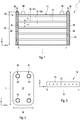
- Fig. 1 schematically shows a reactor 1 in a lateral sectional view through two primary inlet / outlet channels 32.
- the reactor 1 serves to hold a storage material 16 (cf. Fig. 3 ) which emits or absorbs heat while absorbing or desorbing a reaction gas.
- the storage material 16 and the reaction gas are complementary components of a thermochemical reaction system.
- the reactor 1 is optimized for the provision of a high power density and can thus be used, for example, as the core component of an air conditioning system based on a thermochemical reaction system. Due to short reaction times and high power densities, metal hydrides are particularly suitable for this purpose as storage material 16, e.g. B. a titanium-manganese alloy.
- a reaction system suitable for use in an air conditioning system is obtained when hydrogen is used as the reaction gas. This results in suitable reaction temperatures in a suitable pressure window of e.g. B. between 5 bar and 50 bar.
- the reactor 1 comprises a plate heat exchanger 10 with a pressure-tight, for. B. approximately cuboid housing 40 which extends in the y direction over a height H of z. B. extends between 10 cm and 20 cm.
- the plate heat exchanger 10 has a plurality of plates 14, which are arranged orthogonally to the y direction (at least essentially) parallel to one another in xz planes one above the other.
- the plates 14 have (technically) the same dimensions and, in the present example, are essentially rectangular, with a length L (in the x direction) and a width B (in the z direction), with B L L (cf. also Fig. 2 ).
- the length can, for example, be approximately 33 cm and the width approximately 9 cm.
- the number of plates 14 or the height H depends, among other things, on the required output of the reactor 1 in the specific application.
- gap channels 12 are formed or defined, which are bounded by the plates 14 upwards and downwards (in the y direction).
- the gap channels 12 are subdivided into a group of primary gap channels 12a and a group of secondary gap channels 12b, which are each connected in parallel to one another in terms of fluid mechanics and together form a primary or secondary flow channel.
- the primary and secondary gap channels 12a, 12a are arranged alternately with one another.
- the primary gap channels 12a are covered with storage material 16 (cf. Fig. 3 ) filled into which the reaction gas absorbs or from which it desorbs.
- the primary gap channels 12a are in flow communication with, for example, two primary inlet / outlet channels 32 of a primary inlet / outlet arrangement 30, through which the reaction gas (during absorption) from a supply periphery into the storage material 16 or (during the desorption) from the storage material 16 into the supply periphery.
- the primary inlet / outlet channels 32 are each arranged on the two end faces of the plate heat exchanger 10 within the housing 40. Also possible is an arrangement that is offset inwards into the region of the plates 14, such as, for. B. in Fig. 2 shown.
- the reaction gas is fed to or removed from the primary inlet / outlet channels 32 via primary inlet / outlet connections 36 of the primary inlet / outlet arrangement 30.
- the secondary gap channels 12b are designed to conduct a heat transfer fluid.
- the secondary gap channels 12b are in flow connection with inlet / outlet channels 32 of a secondary inlet / outlet arrangement 31 for feeding and / or discharging the heat transfer fluid from the secondary gap channels 12b.
- the inlet / outlet arrangement 32 is e.g. B. part of a (not shown here) heat transfer fluid circuit of an air conditioning arrangement, for example a vehicle.
- Secondary inlet / outlet connections 38 of the secondary inlet / outlet arrangement 31 serve to couple the secondary inlet / outlet channels 34 to a heat transfer fluid circuit.
- the plates 14 can have, in particular on the side facing the secondary gap channels 12b, a surface structure that promotes turbulence, for example a profiling (not shown here). In this way, the heat transfer between the plates 14 and the heat transfer fluid can be improved.
- the primary gap channels 12a each have gap heights s (distance of the plates 14 in the y direction).
- the secondary gap channels 12b each have gap heights h.
- the gap heights s and h in the reactor 1 according to the invention are of different sizes.
- the primary ones The gap channels 12a have a larger gap height s than the secondary gap channels 12b. In this way, a larger (storage) volume is provided for the storage material 16 than the volume through which heat transfer fluid flows, so that there is an overall asymmetrical ratio of the volume filled with storage material 16 to the volume through which fluid can flow or through which fluid flows.
- z. B a ratio of the gap heights h of the secondary gap channels 12b to the gap heights s of the primary gap channels 12a between 1: 3 and 1: 8, preferably between 1: 4 and 1: 6, for example around 1: 4 or 1: 5.
- the gap height h of the secondary gap channels 12b of 1.5 mm has proven to be suitable, while the gap height s of the primary gap channels 12a is approximately 8 mm (with a thermal conductivity of the storage material of, for example, 4 W / (m * K) ).
- the storage material 16 is introduced into the primary gap channels 12a in the form of a compact 20, for example in the form of a pellet or briquette.
- the manufacturing process of the pressed body 20 can be divided into three sub-steps: First, powdery storage material 16, in particular a metal hydride, e.g. B. crushed or homogenized by means of ball mills. It is then mixed with graphite, in particular expanding natural graphite, and then compacted into the pressed bodies 20 of the desired shape.
- the pressed bodies 20 have a porosity, ie a void fraction of, for example, between 30% and 70%, preferably 40% and 60%, for example 50%.
- the Mass transport within the compact 20 ensures, with high (heat) conductivity within the compact 20 of z. B. between 3 and 8 W / (m * K)).
- This value is significantly higher than in the case of powdery storage materials 16, as a result of which significantly higher layer thicknesses can be achieved with the same heat transport properties, which is conducive to the power density.
- there are advantages in reactor production since the influence of contact with oxygen (oxidation) on the operability is minimized and the filling process is simplified.
- the outer dimensions of the pressed body 20 essentially correspond to the (inner) spatial dimensions of the respective primary gap channels 12a. In the present case, this results in an essentially cuboidal configuration of the pressed bodies 20, for example, in the gap channels 12a. B. with a thickness or height (in the y direction) of about 8 mm.
- the pressing body 20 can be arranged in contact with the plates 14, which improves the heat transfer between the individual pressing bodies 20 and the plates 14.
- the pressed bodies 20 and the plates 14 preferably have a complementary surface structure or shape, in particular a smooth surface.
- each gas channels 22 are present in the pressed bodies 20 for guiding the reaction gas within the pressed body 20.
- the respective gas channel 22 is preferably formed by one or more, preferably fluid-mechanically connected, channels 20, for example connected in parallel to one another, which is / are in flow connection with at least one of the primary inlet / outlet channels 32 for supplying or discharging reaction gas.
- the gas channel 22 or the gas channels 22 can already be introduced during the compacting or pressing or z. B. in the form of holes in the wake.
- the gas channel 22 and the gas channels 22 are in the respective Press body 20 is preferably arranged such that the distance of all infinitesimal press body volumes of a respective press body 20 is at most a certain distance of z. B. 40 mm, preferably 20 mm or 10 mm, to the gas channel 22 or the gas channels 22 ("maximum distance") in order to improve the mass transport in operation and to avoid a mass transport limitation.
- the improvement of the mass transfer also serves that, as shown here by way of example, at least two primary inlet / outlet channels 32 are in flow contact with a respective primary gap channel 12a.
- the distance between the primary inlet / outlet channels 32 is a maximum of 200 mm, preferably a maximum of 150 or 100 mm.
- the primary inlet / outlet channels 32 like the secondary inlet / outlet channels 34, can in particular be cylindrical and extend in the y direction, orthogonal to the orientation of the plates 14.
- the inlet / outlet channels 32, 34 extend z. B. in the form of holes through the plates 14 and the pressing body 20 (see. Fig. 2 ). It is also conceivable that, for. B. the primary inlet / outlet channels 32 are each arranged on the end face within the plate heat exchanger 10 (cf. Fig. 1 ).
- filter candles 18 can be arranged in the primary inlet / outlet channels 32.
- the filter candles 18 are dimensioned in particular in such a way that they sit positively in the primary inlet / outlet channels 30.
- the filter candles 18 are preferably made of a sintered metal and / or in hollow form, for. B. hollow cylindrical. In this way, impurities within the reaction gas from the storage material 16, which could clog it and impair its function, can be kept away.
- the reactor 1 can be manufactured in a simple manner by first preassembling several units.
- the units preferably each comprise one of the pressing bodies 20 and at least one, preferably two of the plates 14, in each case on an upper and a lower side of the pressing body 20.
- the units are then joined to one another in a fluid-tight manner, even at high operating pressures of, for example, around 30 bar, in particular using a soldering and / or welding process.
- the filling process of the plate heat exchanger 10 with the storage material 16 is linked to the reactor production.
- the plates 14 to be joined together to form the gap channels 12, the gap channels 12 initially remaining open on one side, for example on an end face (for example in a yz plane).
- the storage material 16 in the form of pressed bodies 20 can then simply be introduced on the open side.
- the open side can then be closed with a wall in a fluid-tight manner, in particular the wall being screwed in a fluid-tight manner to the plate heat exchanger 10 or reactor 20.
- the reactor 1 filled with storage material 16 is brought into operational readiness by means of an activation step. At least one absorption / desorption cycle is carried out. In this way, an oxide layer, which is formed on the pressed body 20 by the oxygen atmosphere, is removed from the pressed body 20. Precycling with several cycles to produce the operational readiness, as is known from the prior art, can advantageously be dispensed with.
- a reactor 1 can be provided for use with a thermochemical reaction system which is further optimized compared to the prior art, in particular with regard to the power density.
Landscapes
- Engineering & Computer Science (AREA)
- Physics & Mathematics (AREA)
- Thermal Sciences (AREA)
- Mechanical Engineering (AREA)
- General Engineering & Computer Science (AREA)
- Chemical & Material Sciences (AREA)
- Chemical Kinetics & Catalysis (AREA)
- General Chemical & Material Sciences (AREA)
- Physical Or Chemical Processes And Apparatus (AREA)
- Devices And Processes Conducted In The Presence Of Fluids And Solid Particles (AREA)
Applications Claiming Priority (1)
| Application Number | Priority Date | Filing Date | Title |
|---|---|---|---|
| DE102019102271.1A DE102019102271B4 (de) | 2019-01-30 | 2019-01-30 | Reaktor zur Aufnahme eines Speichermaterials und Verfahren zur Herstellung desselben |
Publications (3)
| Publication Number | Publication Date |
|---|---|
| EP3689653A1 true EP3689653A1 (fr) | 2020-08-05 |
| EP3689653B1 EP3689653B1 (fr) | 2022-01-26 |
| EP3689653B8 EP3689653B8 (fr) | 2022-03-02 |
Family
ID=69375288
Family Applications (1)
| Application Number | Title | Priority Date | Filing Date |
|---|---|---|---|
| EP20154220.6A Active EP3689653B8 (fr) | 2019-01-30 | 2020-01-29 | Réacteur destiné à recevoir une matière d'accumulation et son procédé de fabrication |
Country Status (3)
| Country | Link |
|---|---|
| EP (1) | EP3689653B8 (fr) |
| DE (1) | DE102019102271B4 (fr) |
| ES (1) | ES2907065T3 (fr) |
Cited By (1)
| Publication number | Priority date | Publication date | Assignee | Title |
|---|---|---|---|---|
| EP4227627A1 (fr) * | 2022-02-15 | 2023-08-16 | Deutsches Zentrum für Luft- und Raumfahrt e.V. | Procédé de stockage d'énergie dans un dispositif de stockage et dispositif de stockage |
Families Citing this family (1)
| Publication number | Priority date | Publication date | Assignee | Title |
|---|---|---|---|---|
| CN112810462A (zh) * | 2021-01-15 | 2021-05-18 | 无锡方盛换热器股份有限公司 | 一种新能源电动车专用复合换热装置 |
Citations (4)
| Publication number | Priority date | Publication date | Assignee | Title |
|---|---|---|---|---|
| FR2666875A1 (fr) * | 1990-09-13 | 1992-03-20 | Bourgogne Technologies | Machine frigorifique a adsorption-desorption sur zeolithes utilisant des echangeurs en profile d'aluminium. |
| US20100024448A1 (en) | 2006-09-08 | 2010-02-04 | University Of Warwick | Heat exchanger |
| DE102013215241A1 (de) * | 2013-06-27 | 2014-12-31 | Robert Bosch Gmbh | Wärmeübertrager |
| DE102016110062B3 (de) | 2016-05-31 | 2017-05-18 | Deutsches Zentrum für Luft- und Raumfahrt e.V. | Reaktor für ein Speichermaterial, welches unter Absorption bzw. Desorption eines Reaktionsgases Wärme aufnimmt bzw. abgibt, bevorzugt für ein Metallhydrid, Verfahren zu dessen Herstellung und Verwendung sowie Befüllvorrichtung |
-
2019
- 2019-01-30 DE DE102019102271.1A patent/DE102019102271B4/de active Active
-
2020
- 2020-01-29 ES ES20154220T patent/ES2907065T3/es active Active
- 2020-01-29 EP EP20154220.6A patent/EP3689653B8/fr active Active
Patent Citations (4)
| Publication number | Priority date | Publication date | Assignee | Title |
|---|---|---|---|---|
| FR2666875A1 (fr) * | 1990-09-13 | 1992-03-20 | Bourgogne Technologies | Machine frigorifique a adsorption-desorption sur zeolithes utilisant des echangeurs en profile d'aluminium. |
| US20100024448A1 (en) | 2006-09-08 | 2010-02-04 | University Of Warwick | Heat exchanger |
| DE102013215241A1 (de) * | 2013-06-27 | 2014-12-31 | Robert Bosch Gmbh | Wärmeübertrager |
| DE102016110062B3 (de) | 2016-05-31 | 2017-05-18 | Deutsches Zentrum für Luft- und Raumfahrt e.V. | Reaktor für ein Speichermaterial, welches unter Absorption bzw. Desorption eines Reaktionsgases Wärme aufnimmt bzw. abgibt, bevorzugt für ein Metallhydrid, Verfahren zu dessen Herstellung und Verwendung sowie Befüllvorrichtung |
Cited By (1)
| Publication number | Priority date | Publication date | Assignee | Title |
|---|---|---|---|---|
| EP4227627A1 (fr) * | 2022-02-15 | 2023-08-16 | Deutsches Zentrum für Luft- und Raumfahrt e.V. | Procédé de stockage d'énergie dans un dispositif de stockage et dispositif de stockage |
Also Published As
| Publication number | Publication date |
|---|---|
| EP3689653B1 (fr) | 2022-01-26 |
| DE102019102271B4 (de) | 2021-09-30 |
| ES2907065T3 (es) | 2022-04-21 |
| DE102019102271A1 (de) | 2020-07-30 |
| EP3689653B8 (fr) | 2022-03-02 |
Similar Documents
| Publication | Publication Date | Title |
|---|---|---|
| EP0687648B1 (fr) | Réformage de méthanol en deux étapes | |
| DE3329245C2 (fr) | ||
| DE102017220297B4 (de) | Wärmetauscher | |
| DE10042245B4 (de) | Wasserstoffspeichervorrichtung und Wasserstoffspeichersystem | |
| DE102015216457A1 (de) | Strahlpumpen für ein Brennstoffzellensystem sowie ein Brennstoffzellensystem | |
| DE112004001761T5 (de) | Druckbehälteranordnung für integriertes Druckfluidsystem | |
| DE1464128A1 (de) | Langgestreckte Bauelemente und Verfahren zu ihrer Herstellung | |
| EP3689653B1 (fr) | Réacteur destiné à recevoir une matière d'accumulation et son procédé de fabrication | |
| WO2012010343A1 (fr) | Dispositif de stockage d'énergie et procédé de stockage réversible d'énergie | |
| EP3024778B1 (fr) | Réacteur destiné à la libération d'hydrogène à partir d'un composé liquide | |
| WO2005013390A2 (fr) | Procede et dispositif de fabrication d'une pile de cellules electrochimiques | |
| DE10392926T5 (de) | Reaktor und Verfahren für präferenzielle Oxidation | |
| WO2023285120A1 (fr) | Système de pile à combustible, ensemble de recirculation pour un système de pile à combustible et procédé pour refroidir un dispositif d'entraînement d'une soufflante de recirculation dans un système de pile à combustible | |
| DE102016110062B3 (de) | Reaktor für ein Speichermaterial, welches unter Absorption bzw. Desorption eines Reaktionsgases Wärme aufnimmt bzw. abgibt, bevorzugt für ein Metallhydrid, Verfahren zu dessen Herstellung und Verwendung sowie Befüllvorrichtung | |
| DE10136970C2 (de) | Vorrichtung zur Erzeugung von wasserstoffhaltigem Gas für eine Brennstoffzellenanlage | |
| EP3894062A1 (fr) | Cascade de réacteurs et procédé pour faire fonctionner une cascade de réacteurs | |
| EP3024568A1 (fr) | Réacteur pour la libération de l'hydrogène d'un composé liquide porteur d'hydrogène | |
| EP0041681A1 (fr) | Dispositif pour la production d'énergie par des flotteurs | |
| AT505873B1 (de) | Suspension für wasserstoffgeneratoren | |
| DE102014006369A1 (de) | Wasserstoffspeicher rnit einem Verbundmaterial und ein Verfahren zur Herstellung | |
| DE69404104T2 (de) | Verfahren zur Verringerung der Zündtemperatur einer exothermen katalytischen Reaktion | |
| DE102018109517A1 (de) | Wärmetauschereinheit | |
| DE102012201755B4 (de) | Verfahren zum Betreiben eines Brennstoffzellensystems sowie Brennstoffzellensystem mit zumindest einer Brennstoffzelle | |
| EP4192804A1 (fr) | Dispositif et procédé de production de méthanol à partir de dioxyde de carbone | |
| DE102012101023B4 (de) | Brennstoffzellenvorrichtung und Verfahren zum Herstellen einer Brennstoffzellenvorrichtung |
Legal Events
| Date | Code | Title | Description |
|---|---|---|---|
| PUAI | Public reference made under article 153(3) epc to a published international application that has entered the european phase |
Free format text: ORIGINAL CODE: 0009012 |
|
| STAA | Information on the status of an ep patent application or granted ep patent |
Free format text: STATUS: THE APPLICATION HAS BEEN PUBLISHED |
|
| AK | Designated contracting states |
Kind code of ref document: A1 Designated state(s): AL AT BE BG CH CY CZ DE DK EE ES FI FR GB GR HR HU IE IS IT LI LT LU LV MC MK MT NL NO PL PT RO RS SE SI SK SM TR |
|
| AX | Request for extension of the european patent |
Extension state: BA ME |
|
| STAA | Information on the status of an ep patent application or granted ep patent |
Free format text: STATUS: REQUEST FOR EXAMINATION WAS MADE |
|
| 17P | Request for examination filed |
Effective date: 20210205 |
|
| RBV | Designated contracting states (corrected) |
Designated state(s): AL AT BE BG CH CY CZ DE DK EE ES FI FR GB GR HR HU IE IS IT LI LT LU LV MC MK MT NL NO PL PT RO RS SE SI SK SM TR |
|
| GRAP | Despatch of communication of intention to grant a patent |
Free format text: ORIGINAL CODE: EPIDOSNIGR1 |
|
| STAA | Information on the status of an ep patent application or granted ep patent |
Free format text: STATUS: GRANT OF PATENT IS INTENDED |
|
| RIC1 | Information provided on ipc code assigned before grant |
Ipc: F28D 9/00 20060101ALI20210908BHEP Ipc: F25B 39/02 20060101ALI20210908BHEP Ipc: B60H 1/32 20060101AFI20210908BHEP |
|
| INTG | Intention to grant announced |
Effective date: 20210928 |
|
| GRAS | Grant fee paid |
Free format text: ORIGINAL CODE: EPIDOSNIGR3 |
|
| GRAA | (expected) grant |
Free format text: ORIGINAL CODE: 0009210 |
|
| STAA | Information on the status of an ep patent application or granted ep patent |
Free format text: STATUS: THE PATENT HAS BEEN GRANTED |
|
| AK | Designated contracting states |
Kind code of ref document: B1 Designated state(s): AL AT BE BG CH CY CZ DE DK EE ES FI FR GB GR HR HU IE IS IT LI LT LU LV MC MK MT NL NO PL PT RO RS SE SI SK SM TR |
|
| REG | Reference to a national code |
Ref country code: GB Ref legal event code: FG4D Free format text: NOT ENGLISH |
|
| REG | Reference to a national code |
Ref country code: CH Ref legal event code: EP |
|
| REG | Reference to a national code |
Ref country code: DE Ref legal event code: R081 Ref document number: 502020000578 Country of ref document: DE Owner name: DEUTSCHES ZENTRUM FUER LUFT- UND RAUMFAHRT E.V, DE Free format text: FORMER OWNER: DEUTSCHES ZENTRUM FUER LUFT- UND RAUMFAHRT E.V., 51147 KOELN, DE |
|
| REG | Reference to a national code |
Ref country code: CH Ref legal event code: PK Free format text: BERICHTIGUNG B8 Ref country code: AT Ref legal event code: REF Ref document number: 1465005 Country of ref document: AT Kind code of ref document: T Effective date: 20220215 |
|
| REG | Reference to a national code |
Ref country code: IE Ref legal event code: FG4D Free format text: LANGUAGE OF EP DOCUMENT: GERMAN |
|
| REG | Reference to a national code |
Ref country code: DE Ref legal event code: R096 Ref document number: 502020000578 Country of ref document: DE |
|
| RAP4 | Party data changed (patent owner data changed or rights of a patent transferred) |
Owner name: DEUTSCHES ZENTRUM FUER LUFT- UND RAUMFAHRT E.V. |
|
| REG | Reference to a national code |
Ref country code: SE Ref legal event code: TRGR |
|
| REG | Reference to a national code |
Ref country code: ES Ref legal event code: FG2A Ref document number: 2907065 Country of ref document: ES Kind code of ref document: T3 Effective date: 20220421 |
|
| REG | Reference to a national code |
Ref country code: LT Ref legal event code: MG9D |
|
| REG | Reference to a national code |
Ref country code: NL Ref legal event code: MP Effective date: 20220126 |
|
| PG25 | Lapsed in a contracting state [announced via postgrant information from national office to epo] |
Ref country code: NL Free format text: LAPSE BECAUSE OF FAILURE TO SUBMIT A TRANSLATION OF THE DESCRIPTION OR TO PAY THE FEE WITHIN THE PRESCRIBED TIME-LIMIT Effective date: 20220126 |
|
| PG25 | Lapsed in a contracting state [announced via postgrant information from national office to epo] |
Ref country code: SK Free format text: LAPSE BECAUSE OF FAILURE TO SUBMIT A TRANSLATION OF THE DESCRIPTION OR TO PAY THE FEE WITHIN THE PRESCRIBED TIME-LIMIT Effective date: 20220126 Ref country code: RS Free format text: LAPSE BECAUSE OF FAILURE TO SUBMIT A TRANSLATION OF THE DESCRIPTION OR TO PAY THE FEE WITHIN THE PRESCRIBED TIME-LIMIT Effective date: 20220126 Ref country code: PT Free format text: LAPSE BECAUSE OF FAILURE TO SUBMIT A TRANSLATION OF THE DESCRIPTION OR TO PAY THE FEE WITHIN THE PRESCRIBED TIME-LIMIT Effective date: 20220526 Ref country code: NO Free format text: LAPSE BECAUSE OF FAILURE TO SUBMIT A TRANSLATION OF THE DESCRIPTION OR TO PAY THE FEE WITHIN THE PRESCRIBED TIME-LIMIT Effective date: 20220426 Ref country code: LT Free format text: LAPSE BECAUSE OF FAILURE TO SUBMIT A TRANSLATION OF THE DESCRIPTION OR TO PAY THE FEE WITHIN THE PRESCRIBED TIME-LIMIT Effective date: 20220126 Ref country code: HR Free format text: LAPSE BECAUSE OF FAILURE TO SUBMIT A TRANSLATION OF THE DESCRIPTION OR TO PAY THE FEE WITHIN THE PRESCRIBED TIME-LIMIT Effective date: 20220126 Ref country code: BG Free format text: LAPSE BECAUSE OF FAILURE TO SUBMIT A TRANSLATION OF THE DESCRIPTION OR TO PAY THE FEE WITHIN THE PRESCRIBED TIME-LIMIT Effective date: 20220426 |
|
| PG25 | Lapsed in a contracting state [announced via postgrant information from national office to epo] |
Ref country code: PL Free format text: LAPSE BECAUSE OF FAILURE TO SUBMIT A TRANSLATION OF THE DESCRIPTION OR TO PAY THE FEE WITHIN THE PRESCRIBED TIME-LIMIT Effective date: 20220126 Ref country code: LV Free format text: LAPSE BECAUSE OF FAILURE TO SUBMIT A TRANSLATION OF THE DESCRIPTION OR TO PAY THE FEE WITHIN THE PRESCRIBED TIME-LIMIT Effective date: 20220126 Ref country code: GR Free format text: LAPSE BECAUSE OF FAILURE TO SUBMIT A TRANSLATION OF THE DESCRIPTION OR TO PAY THE FEE WITHIN THE PRESCRIBED TIME-LIMIT Effective date: 20220427 Ref country code: FI Free format text: LAPSE BECAUSE OF FAILURE TO SUBMIT A TRANSLATION OF THE DESCRIPTION OR TO PAY THE FEE WITHIN THE PRESCRIBED TIME-LIMIT Effective date: 20220126 |
|
| PG25 | Lapsed in a contracting state [announced via postgrant information from national office to epo] |
Ref country code: IS Free format text: LAPSE BECAUSE OF FAILURE TO SUBMIT A TRANSLATION OF THE DESCRIPTION OR TO PAY THE FEE WITHIN THE PRESCRIBED TIME-LIMIT Effective date: 20220526 |
|
| REG | Reference to a national code |
Ref country code: BE Ref legal event code: MM Effective date: 20220131 |
|
| REG | Reference to a national code |
Ref country code: DE Ref legal event code: R097 Ref document number: 502020000578 Country of ref document: DE |
|
| PG25 | Lapsed in a contracting state [announced via postgrant information from national office to epo] |
Ref country code: SM Free format text: LAPSE BECAUSE OF FAILURE TO SUBMIT A TRANSLATION OF THE DESCRIPTION OR TO PAY THE FEE WITHIN THE PRESCRIBED TIME-LIMIT Effective date: 20220126 Ref country code: RO Free format text: LAPSE BECAUSE OF FAILURE TO SUBMIT A TRANSLATION OF THE DESCRIPTION OR TO PAY THE FEE WITHIN THE PRESCRIBED TIME-LIMIT Effective date: 20220126 Ref country code: MC Free format text: LAPSE BECAUSE OF FAILURE TO SUBMIT A TRANSLATION OF THE DESCRIPTION OR TO PAY THE FEE WITHIN THE PRESCRIBED TIME-LIMIT Effective date: 20220126 Ref country code: LU Free format text: LAPSE BECAUSE OF NON-PAYMENT OF DUE FEES Effective date: 20220129 Ref country code: EE Free format text: LAPSE BECAUSE OF FAILURE TO SUBMIT A TRANSLATION OF THE DESCRIPTION OR TO PAY THE FEE WITHIN THE PRESCRIBED TIME-LIMIT Effective date: 20220126 Ref country code: DK Free format text: LAPSE BECAUSE OF FAILURE TO SUBMIT A TRANSLATION OF THE DESCRIPTION OR TO PAY THE FEE WITHIN THE PRESCRIBED TIME-LIMIT Effective date: 20220126 Ref country code: CZ Free format text: LAPSE BECAUSE OF FAILURE TO SUBMIT A TRANSLATION OF THE DESCRIPTION OR TO PAY THE FEE WITHIN THE PRESCRIBED TIME-LIMIT Effective date: 20220126 |
|
| PG25 | Lapsed in a contracting state [announced via postgrant information from national office to epo] |
Ref country code: BE Free format text: LAPSE BECAUSE OF NON-PAYMENT OF DUE FEES Effective date: 20220131 Ref country code: AL Free format text: LAPSE BECAUSE OF FAILURE TO SUBMIT A TRANSLATION OF THE DESCRIPTION OR TO PAY THE FEE WITHIN THE PRESCRIBED TIME-LIMIT Effective date: 20220126 |
|
| PLBE | No opposition filed within time limit |
Free format text: ORIGINAL CODE: 0009261 |
|
| STAA | Information on the status of an ep patent application or granted ep patent |
Free format text: STATUS: NO OPPOSITION FILED WITHIN TIME LIMIT |
|
| 26N | No opposition filed |
Effective date: 20221027 |
|
| PG25 | Lapsed in a contracting state [announced via postgrant information from national office to epo] |
Ref country code: IE Free format text: LAPSE BECAUSE OF NON-PAYMENT OF DUE FEES Effective date: 20220129 |
|
| PG25 | Lapsed in a contracting state [announced via postgrant information from national office to epo] |
Ref country code: SI Free format text: LAPSE BECAUSE OF FAILURE TO SUBMIT A TRANSLATION OF THE DESCRIPTION OR TO PAY THE FEE WITHIN THE PRESCRIBED TIME-LIMIT Effective date: 20220126 |
|
| PG25 | Lapsed in a contracting state [announced via postgrant information from national office to epo] |
Ref country code: IT Free format text: LAPSE BECAUSE OF FAILURE TO SUBMIT A TRANSLATION OF THE DESCRIPTION OR TO PAY THE FEE WITHIN THE PRESCRIBED TIME-LIMIT Effective date: 20220126 |
|
| REG | Reference to a national code |
Ref country code: CH Ref legal event code: PL |
|
| PG25 | Lapsed in a contracting state [announced via postgrant information from national office to epo] |
Ref country code: LI Free format text: LAPSE BECAUSE OF NON-PAYMENT OF DUE FEES Effective date: 20230131 Ref country code: CH Free format text: LAPSE BECAUSE OF NON-PAYMENT OF DUE FEES Effective date: 20230131 |
|
| PG25 | Lapsed in a contracting state [announced via postgrant information from national office to epo] |
Ref country code: MK Free format text: LAPSE BECAUSE OF FAILURE TO SUBMIT A TRANSLATION OF THE DESCRIPTION OR TO PAY THE FEE WITHIN THE PRESCRIBED TIME-LIMIT Effective date: 20220126 Ref country code: CY Free format text: LAPSE BECAUSE OF FAILURE TO SUBMIT A TRANSLATION OF THE DESCRIPTION OR TO PAY THE FEE WITHIN THE PRESCRIBED TIME-LIMIT Effective date: 20220126 |
|
| PG25 | Lapsed in a contracting state [announced via postgrant information from national office to epo] |
Ref country code: HU Free format text: LAPSE BECAUSE OF FAILURE TO SUBMIT A TRANSLATION OF THE DESCRIPTION OR TO PAY THE FEE WITHIN THE PRESCRIBED TIME-LIMIT; INVALID AB INITIO Effective date: 20200129 |
|
| PG25 | Lapsed in a contracting state [announced via postgrant information from national office to epo] |
Ref country code: TR Free format text: LAPSE BECAUSE OF FAILURE TO SUBMIT A TRANSLATION OF THE DESCRIPTION OR TO PAY THE FEE WITHIN THE PRESCRIBED TIME-LIMIT Effective date: 20220126 |
|
| GBPC | Gb: european patent ceased through non-payment of renewal fee |
Effective date: 20240129 |
|
| PG25 | Lapsed in a contracting state [announced via postgrant information from national office to epo] |
Ref country code: MT Free format text: LAPSE BECAUSE OF FAILURE TO SUBMIT A TRANSLATION OF THE DESCRIPTION OR TO PAY THE FEE WITHIN THE PRESCRIBED TIME-LIMIT Effective date: 20220126 |
|
| PG25 | Lapsed in a contracting state [announced via postgrant information from national office to epo] |
Ref country code: GB Free format text: LAPSE BECAUSE OF NON-PAYMENT OF DUE FEES Effective date: 20240129 |
|
| PG25 | Lapsed in a contracting state [announced via postgrant information from national office to epo] |
Ref country code: GB Free format text: LAPSE BECAUSE OF NON-PAYMENT OF DUE FEES Effective date: 20240129 |
|
| PGFP | Annual fee paid to national office [announced via postgrant information from national office to epo] |
Ref country code: AT Payment date: 20250417 Year of fee payment: 5 |
|
| PGFP | Annual fee paid to national office [announced via postgrant information from national office to epo] |
Ref country code: FR Payment date: 20251216 Year of fee payment: 7 |
|
| REG | Reference to a national code |
Ref country code: AT Ref legal event code: MM01 Ref document number: 1465005 Country of ref document: AT Kind code of ref document: T Effective date: 20250129 |
|
| PGFP | Annual fee paid to national office [announced via postgrant information from national office to epo] |
Ref country code: SE Payment date: 20260109 Year of fee payment: 7 |
|
| PGFP | Annual fee paid to national office [announced via postgrant information from national office to epo] |
Ref country code: ES Payment date: 20260205 Year of fee payment: 7 |
|
| PGFP | Annual fee paid to national office [announced via postgrant information from national office to epo] |
Ref country code: DE Payment date: 20251222 Year of fee payment: 7 |
|
| PG25 | Lapsed in a contracting state [announced via postgrant information from national office to epo] |
Ref country code: AT Free format text: LAPSE BECAUSE OF NON-PAYMENT OF DUE FEES Effective date: 20250129 |