EP3689683A1 - Dispositif lumineux pour un véhicule automobile - Google Patents
Dispositif lumineux pour un véhicule automobile Download PDFInfo
- Publication number
- EP3689683A1 EP3689683A1 EP19155389.0A EP19155389A EP3689683A1 EP 3689683 A1 EP3689683 A1 EP 3689683A1 EP 19155389 A EP19155389 A EP 19155389A EP 3689683 A1 EP3689683 A1 EP 3689683A1
- Authority
- EP
- European Patent Office
- Prior art keywords
- light
- optical part
- input face
- portions
- face
- Prior art date
- Legal status (The legal status is an assumption and is not a legal conclusion. Google has not performed a legal analysis and makes no representation as to the accuracy of the status listed.)
- Granted
Links
Images


Classifications
-
- F—MECHANICAL ENGINEERING; LIGHTING; HEATING; WEAPONS; BLASTING
- F21—LIGHTING
- F21S—NON-PORTABLE LIGHTING DEVICES; SYSTEMS THEREOF; VEHICLE LIGHTING DEVICES SPECIALLY ADAPTED FOR VEHICLE EXTERIORS
- F21S43/00—Signalling devices specially adapted for vehicle exteriors, e.g. brake lamps, direction indicator lights or reversing lights
- F21S43/20—Signalling devices specially adapted for vehicle exteriors, e.g. brake lamps, direction indicator lights or reversing lights characterised by refractors, transparent cover plates, light guides or filters
- F21S43/2605—Refractors
-
- B—PERFORMING OPERATIONS; TRANSPORTING
- B60—VEHICLES IN GENERAL
- B60Q—ARRANGEMENT OF SIGNALLING OR LIGHTING DEVICES, THE MOUNTING OR SUPPORTING THEREOF OR CIRCUITS THEREFOR, FOR VEHICLES IN GENERAL
- B60Q1/00—Arrangement of optical signalling or lighting devices, the mounting or supporting thereof or circuits therefor
- B60Q1/26—Arrangement of optical signalling or lighting devices, the mounting or supporting thereof or circuits therefor the devices being primarily intended to indicate the vehicle, or parts thereof, or to give signals, to other traffic
- B60Q1/2607—Arrangement of optical signalling or lighting devices, the mounting or supporting thereof or circuits therefor the devices being primarily intended to indicate the vehicle, or parts thereof, or to give signals, to other traffic comprising at least two indicating lamps
-
- F—MECHANICAL ENGINEERING; LIGHTING; HEATING; WEAPONS; BLASTING
- F21—LIGHTING
- F21S—NON-PORTABLE LIGHTING DEVICES; SYSTEMS THEREOF; VEHICLE LIGHTING DEVICES SPECIALLY ADAPTED FOR VEHICLE EXTERIORS
- F21S43/00—Signalling devices specially adapted for vehicle exteriors, e.g. brake lamps, direction indicator lights or reversing lights
- F21S43/20—Signalling devices specially adapted for vehicle exteriors, e.g. brake lamps, direction indicator lights or reversing lights characterised by refractors, transparent cover plates, light guides or filters
- F21S43/26—Refractors, transparent cover plates, light guides or filters not provided in groups F21S43/235 - F21S43/255
-
- F—MECHANICAL ENGINEERING; LIGHTING; HEATING; WEAPONS; BLASTING
- F21—LIGHTING
- F21S—NON-PORTABLE LIGHTING DEVICES; SYSTEMS THEREOF; VEHICLE LIGHTING DEVICES SPECIALLY ADAPTED FOR VEHICLE EXTERIORS
- F21S43/00—Signalling devices specially adapted for vehicle exteriors, e.g. brake lamps, direction indicator lights or reversing lights
- F21S43/30—Signalling devices specially adapted for vehicle exteriors, e.g. brake lamps, direction indicator lights or reversing lights characterised by reflectors
- F21S43/31—Optical layout thereof
- F21S43/315—Optical layout thereof using total internal reflection
-
- F—MECHANICAL ENGINEERING; LIGHTING; HEATING; WEAPONS; BLASTING
- F21—LIGHTING
- F21S—NON-PORTABLE LIGHTING DEVICES; SYSTEMS THEREOF; VEHICLE LIGHTING DEVICES SPECIALLY ADAPTED FOR VEHICLE EXTERIORS
- F21S43/00—Signalling devices specially adapted for vehicle exteriors, e.g. brake lamps, direction indicator lights or reversing lights
- F21S43/40—Signalling devices specially adapted for vehicle exteriors, e.g. brake lamps, direction indicator lights or reversing lights characterised by the combination of reflectors and refractors
- F21S43/402—Total internal reflection [TIR] collimators
-
- G—PHYSICS
- G02—OPTICS
- G02B—OPTICAL ELEMENTS, SYSTEMS OR APPARATUS
- G02B19/00—Condensers, e.g. light collectors or similar non-imaging optics
- G02B19/0004—Condensers, e.g. light collectors or similar non-imaging optics characterised by the optical means employed
- G02B19/0028—Condensers, e.g. light collectors or similar non-imaging optics characterised by the optical means employed refractive and reflective surfaces, e.g. non-imaging catadioptric systems
-
- G—PHYSICS
- G02—OPTICS
- G02B—OPTICAL ELEMENTS, SYSTEMS OR APPARATUS
- G02B19/00—Condensers, e.g. light collectors or similar non-imaging optics
- G02B19/0033—Condensers, e.g. light collectors or similar non-imaging optics characterised by the use
- G02B19/0047—Condensers, e.g. light collectors or similar non-imaging optics characterised by the use for use with a light source
- G02B19/0061—Condensers, e.g. light collectors or similar non-imaging optics characterised by the use for use with a light source the light source comprising a LED
- G02B19/0066—Condensers, e.g. light collectors or similar non-imaging optics characterised by the use for use with a light source the light source comprising a LED in the form of an LED array
-
- G—PHYSICS
- G02—OPTICS
- G02B—OPTICAL ELEMENTS, SYSTEMS OR APPARATUS
- G02B19/00—Condensers, e.g. light collectors or similar non-imaging optics
- G02B19/0033—Condensers, e.g. light collectors or similar non-imaging optics characterised by the use
- G02B19/0047—Condensers, e.g. light collectors or similar non-imaging optics characterised by the use for use with a light source
- G02B19/0071—Condensers, e.g. light collectors or similar non-imaging optics characterised by the use for use with a light source adapted to illuminate a complete hemisphere or a plane extending 360 degrees around the source
-
- B—PERFORMING OPERATIONS; TRANSPORTING
- B60—VEHICLES IN GENERAL
- B60Q—ARRANGEMENT OF SIGNALLING OR LIGHTING DEVICES, THE MOUNTING OR SUPPORTING THEREOF OR CIRCUITS THEREFOR, FOR VEHICLES IN GENERAL
- B60Q2400/00—Special features or arrangements of exterior signal lamps for vehicles
- B60Q2400/20—Multi-color single source or LED matrix, e.g. yellow blinker and red brake lamp generated by single lamp
-
- B—PERFORMING OPERATIONS; TRANSPORTING
- B60—VEHICLES IN GENERAL
- B60Q—ARRANGEMENT OF SIGNALLING OR LIGHTING DEVICES, THE MOUNTING OR SUPPORTING THEREOF OR CIRCUITS THEREFOR, FOR VEHICLES IN GENERAL
- B60Q3/00—Arrangement of lighting devices for vehicle interiors; Lighting devices specially adapted for vehicle interiors
- B60Q3/60—Arrangement of lighting devices for vehicle interiors; Lighting devices specially adapted for vehicle interiors characterised by optical aspects
- B60Q3/62—Arrangement of lighting devices for vehicle interiors; Lighting devices specially adapted for vehicle interiors characterised by optical aspects using light guides
- B60Q3/64—Arrangement of lighting devices for vehicle interiors; Lighting devices specially adapted for vehicle interiors characterised by optical aspects using light guides for a single lighting device
-
- B—PERFORMING OPERATIONS; TRANSPORTING
- B60—VEHICLES IN GENERAL
- B60Q—ARRANGEMENT OF SIGNALLING OR LIGHTING DEVICES, THE MOUNTING OR SUPPORTING THEREOF OR CIRCUITS THEREFOR, FOR VEHICLES IN GENERAL
- B60Q3/00—Arrangement of lighting devices for vehicle interiors; Lighting devices specially adapted for vehicle interiors
- B60Q3/70—Arrangement of lighting devices for vehicle interiors; Lighting devices specially adapted for vehicle interiors characterised by the purpose
- B60Q3/74—Arrangement of lighting devices for vehicle interiors; Lighting devices specially adapted for vehicle interiors characterised by the purpose for overall compartment lighting; for overall compartment lighting in combination with specific lighting, e.g. room lamps with reading lamps
- B60Q3/745—Arrangement of lighting devices for vehicle interiors; Lighting devices specially adapted for vehicle interiors characterised by the purpose for overall compartment lighting; for overall compartment lighting in combination with specific lighting, e.g. room lamps with reading lamps using lighting panels or mats, e.g. electro-luminescent panels, LED mats
-
- F—MECHANICAL ENGINEERING; LIGHTING; HEATING; WEAPONS; BLASTING
- F21—LIGHTING
- F21S—NON-PORTABLE LIGHTING DEVICES; SYSTEMS THEREOF; VEHICLE LIGHTING DEVICES SPECIALLY ADAPTED FOR VEHICLE EXTERIORS
- F21S43/00—Signalling devices specially adapted for vehicle exteriors, e.g. brake lamps, direction indicator lights or reversing lights
- F21S43/10—Signalling devices specially adapted for vehicle exteriors, e.g. brake lamps, direction indicator lights or reversing lights characterised by the light source
- F21S43/13—Signalling devices specially adapted for vehicle exteriors, e.g. brake lamps, direction indicator lights or reversing lights characterised by the light source characterised by the type of light source
- F21S43/14—Light emitting diodes [LED]
Definitions
- the present invention relates to a light emitting device for an automotive vehicle.
- Light emitting devices for an automotive vehicle are placed on the exterior of automotive vehicles, especially for security purposes, to indicate to other road users the presence of the vehicle, as well as the intensions of the driver of the vehicle, such as breaking, changing the driving direction or reversing.
- Other devices are placed inside the vehicle to illuminate the passengers, to welcome them when they enter the vehicle, or to create a special ambience light in the cabin.
- the known light emitting devices which have good homogeneity, are generally bulky. Conversely, those that are not bulky have a poor homogeneity. In addition, they are also poorly adapted to ensure a good homogeneity when they emit several light functions.
- An object of the present invention is to solve the disadvantages described above of known light emitting devices of an automotive vehicle.
- the object of the present invention is to provide a light emitting device, which is not bulky and can ensure a good homogeneity when it performs several lighting and/or signaling functions, for example, tail lighting function and turn indicator function.
- the invention proposes a light emitting module comprising an optical part according to the invention.
- an optical part for an automotive vehicle comprising:
- the at least second portion protrudes from the at least first portion.
- the second light input face is situated at one extremity of the second portion that is protruded from the first portion.
- the second light input face is flat.
- the second light input face is curved and/or comports a collimator.
- the first light input face is flat.
- the first light input face is curved.
- the first light input face comprises optical pattern, especially pillows and/or flutes and/or cones and/or a graining.
- the first light input face comports hollow cones.
- the cones have an apical angle comprised between 30° and 60°, and preferably an apical angle of of 45° with respect to a respective axis of rotation of the cones.
- the cones have a depth comprised between 0.15 and 0.3mm, especially 0.2mm.
- the output face is curved.
- the optical part comprises a plurality of first portions comprising each a first light input face and a plurality of second portions comprising each a second light input face.
- the first input faces of the first portions form a connected surface.
- the second portions are disjointed.
- the second portions are arranged in matrix.
- each second portions has a form of a cylinder or a cone.
- each second portions is rotationally symmetrical.
- the output face comprises a plurality of curved portions.
- the output face comprises a plurality of hollow portions.
- the hollow portions are each rotationally symmetrical, especially have a conical form with an apex.
- the generating curve of the conical form is curved.
- the hollow portions are disjointed.
- each hollow portions is opposite an associated second portion.
- the apex of the conical form is centered on a central axis of its associated second portion.
- the curved portions are arranged in a matrix, and alternating with the hollow portions.
- the light emitting module comprises:
- the light emitting module comprises:
- each first light input face is associated to a first light source.
- each second input face is associated to a second light source.
- the plurality of first light sources and the plurality of second light sources are semi-conductor light sources, especially light emitting diodes.
- the plurality of first light sources is adapted to emit a light flux different from the light flux emitted by the plurality of second light sources.
- the plurality of first light sources and the plurality of second light sources are configured for emitting a light color chosen from red, amber, yellow or white .
- the plurality of first light sources is adapted to emit a light color different from the light color emitted by the plurality of second light sources.
- the plurality of first light sources are disposed on a common support.
- the plurality of second light sources are disposed on a common support.
- the plurality of first light sources and the plurality of second light sources are disposed on a common support.
- the present invention also proposes, a light emitting device comprising:
- the light emitting device further comprises an outer lens closing the front opening of the housing, the at least one light emitting module being placed in the volume formed by the housing and the outer lens.
- the light emitting device is a rear lamp, a headlamp, or an internal lighting device, of an automotive vehicle.
- the light emitting device is an internal lighting device of an automotive vehicle, the optical part closing the front opening of the housing.
- the present invention is to provide a light emitting device, which is not bulky and can ensure a good homogeneity when it emits several light functions
- the present invention provides a light emitting device, which ensures a good homogeneity when it emits several lighting and/or signaling functions, for example, tail function and turn indicator function, tail function and stop function, position or parking function and DRL (for "Daytime Running Lamp”) function, position or parking function and turn indicator function.
- lighting and/or signaling functions for example, tail function and turn indicator function, tail function and stop function, position or parking function and DRL (for "Daytime Running Lamp") function, position or parking function and turn indicator function.
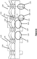
- Figure 1a shows a perspective view of an optical part of a light emitting device, according to an embodiment of the present invention.
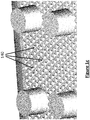
- Figure 1b shows a bottom view of the optical part of the Figure 1a , according to an embodiment of the present invention.
- Figure 1c shows enlarged view of the bottom portion of the optical part shown in the Figure 1b , according to an embodiment of the present invention.
- Figure 1d shows a top view of the optical part of the Figure 1a , according to an embodiment of the present invention.
- the optical part 100 of an automotive vehicle comprises at least a first portion 105 comprising a first light input face 110 for receiving first light rays from a first light source 205 (shown in the Figure 2 ) and transmitting first light rays directly toward a light output face 115, so that the first light rays exit the optical part 100.
- the optical part 100 further comprises at least a second portion 120 comprising a second light input face 125 for receiving second light rays from a second light source 210 (shown in the Figure 2 ) and transmitting the second light rays toward the light output face 115 so that the second light rays are reflected at least one time by total internal reflection on a first zone 215 (shown in the Figure 2 ) of the light output face 115 before exiting the optical part 100 through a second zone 220 (shown in the Figure 2 ) of the light output face 115.
- the light output face 115 is curve shaped.
- the at least second portion 120 of the optical part 100 protrudes from the at least first portion 105 of the optical part 100.
- the at least a second portion 120 has a form of a cone or a cylinder.
- the second light input face 125 is situated at one extremity of the second portion 120 that is protruded from the first portion 105.
- the second light input face 125 may be flat shaped as shown in the Figure 1a .
- the second light input face may be curve shaped and/or comprise a collimator (not shown in the Figures) to collimate the light emitted from the second light source 210.
- the first light input face 110 may be flat shaped as shown in the Figure 1a .
- the first light input face 110 may be curve shaped and/or comprise a collimator (not shown in the Figures) to collimate the light emitted from the second light source 210.
- the first light input face 110 may comprise optical patterns 145, which are clearly visible in the Figure 1b .
- the optical patterns 145 may be pillows and/or flutes and/or cones and/or a graining.
- the first light input face 110 may comprise hollow cones 140 as shown in the Figure 1c .
- Each cone 140 has an apical angle or half-opening angle.
- the half-opening angle is between 30° and 60°, and preferably 45° with respect to an axis of rotation of the cone.
- Each cone 140 has a depth between 0.15 mm and 0.3mm, especially 0.2mm.
- the optical part 100 comprises a plurality of first portions 105 and a plurality of second portions 120.
- Each first portion 105 comprises a first light input face 110 for receiving the first light rays from the first light source 205.
- each second portion 120 comprises a second light input face 125 for receiving the second light rays from the second light source 210.
- the first input faces 110 of the first portions 105 form a connected surface and the second portions 120 are disjointed.
- the second portions 120 may be arranged in matrix, which is a grid organized in rows and columns.
- Each second portion 120 has a shape of a cylinder or a cone, and each second portion 120 is rotationally symmetrical. In one embodiment all the second portions have the same shape.
- each first portion 105 can be associated to several second portions 120, i.e., the light coming from several second portions120 can be directed to one given first portion output face 115.
- the light output face 115 comprises a plurality of curved portions 130 and a plurality of hollow portions 135.
- Each hollow portion 135 is rotationally symmetrical, and especially have a conical form with an apex. Further, the hollow portions 135 of the output face 115 are disjointed as shown in the Figure 1a .
- Each hollow portion 135 is opposite to an associated second portion 120 and an apex of the conical form of the hollow portion 135 is centered on a central axis 'C' of its associated second portion 120.
- the curved portions 130 of the light output face 115 may be arranged in a matrix, and alternating with the hollow portions 135, as shown in the Figure 1a .
- Figure 2 is a sectional representation of an optical part 100 shown in the Figure 1a , according to an embodiment of the present invention.
- the section is obtained by a plane perpendicular to a global elongation plane of the optical part 100 and through the center of two second portions 120.
- the optical part 100 of the present invention ensure a good homogeneity when it emits several lighting and/or signaling functions, for example, tail lighting function and turn indicator function, tail function and stop function, position or parking function and DRL (for "Daytime Running Lamp") function, position or parking function and turn indicator function.
- the plurality of first light sources 205 and the plurality of the second light sources 210 are configured for emitting a light color chosen from red, amber, yellow or white in order to perform several lighting and/or signaling functions.
- the purpose of emitting different colors for performing different lighting and/or signaling function is known to a person skilled in the art, and therefore not discussed in detail in this description.
- first light rays 230 emitted from the first light source 205 is indicated by dotted arrows A. It is to be noted that only half of the first light rays is shown in the Figure 2 and Figure 3b for the purpose of the clarity. However, the rays symmetric about a not represented vertical axis centered on the light source also exist.
- First light rays emitted from the first light source 205 enter into the optical part 100 through the first light input face 110 and are directly transmitted to the light output face 115, i.e., first light rays exit the optical part 100 from the curved portion 130 of the light output face 115.
- Second light rays 240 emitted from the second light source 210 enter into the optical part 100 through the second light input face 125 and are transmitted towards first zones 215 of the light output face 115 through the second portion 120. From the second portion 120, transmitted second light rays meet the hollow portion 135 of the light output face 115 where they are reflected at least one time and exit the optical part 100 through the second zones 220 of the light output face 115.
- Dotted arrows B in the Figure 2 show the path of second light rays emitted from the second light source 210.
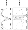
- the path of the light rays emitted from the first light source 205 to perform the first lighting/signaling function and path of the light rays emitted from the second light source 210 to perform the second lighting/signaling function is separately shown in the Figure 3a and the Figure 3b . Therefore, in accordance with present invention, single optical part can be used to perform several lighting and/or signaling functions, rather than using several parts for performing several functions.
- a light emitting module comprises an optical part 100 having at least one first portion 105 and at least one second portion 120, as mentioned in previously discussed embodiment.
- the light emitting module further comprises at least a first light source 205 placed opposite the first light input face 110 of the at least first portion 105.
- the light emitting module comprises a second light source 210 placed opposite the second light input face 125 of the at least second portion 120.
- a light emitting module having a plurality of first portions 105 and a plurality of second portions 120 is disclosed.
- the light emitting module comprises a plurality of first light sources 205 each opposite an associated first light input face 110 of the first portion 105, and a plurality of second light sources 210 each opposite an associated second light input face 125 of the second portion 120.
- Each first portion 105 is associated to a first light source 205 and each second portion 120 is associated to a second light source 210.
- the plurality of first light sources 205 and the plurality of the second light sources 210 are semi-conductor light sources, for example, light emitting diodes. Further, the plurality of first light sources 205 is adapted to emit a light flux different from the light flux emitted by the plurality of the second light sources 210. In addition, the plurality of first light sources 205 is adapted to emit a light color different from the light color emitted by the plurality of second light sources 210. In an aspect, the plurality of first light sources 205 are disposed on a common support, and the plurality of the second light sources 210 are disposed on another common support. In another aspect, both the plurality of first light sources 205 and the plurality of second light sources 210 are disposed on a single common support.
- the present invention discloses a light emitting device comprising a housing comprising an opening, and at least one light emitting module described in the above embodiments.
- the at least one light emitting module is placed in the housing.
- the light emitting device further comprises an outer lens closing the front opening of the housing, the at least one light emitting module being placed in the volume formed by the housing and the outer lens.
- the light emitting device may be either a rear lamp or a headlamp of the automotive vehicle.
- the light emitting device is an internal lighting device of the automotive vehicle, where the optical part closes the front opening of the housing.
- the light emitting device of the present invention can perform several lighting and/or signaling functions using a single optical part, and therefore occupies less space compared to conventional light emitting devices.
Landscapes
- Engineering & Computer Science (AREA)
- Physics & Mathematics (AREA)
- General Engineering & Computer Science (AREA)
- Optics & Photonics (AREA)
- General Physics & Mathematics (AREA)
- Mechanical Engineering (AREA)
- Microelectronics & Electronic Packaging (AREA)
- Non-Portable Lighting Devices Or Systems Thereof (AREA)
- Planar Illumination Modules (AREA)
Priority Applications (5)
| Application Number | Priority Date | Filing Date | Title |
|---|---|---|---|
| EP19155389.0A EP3689683B1 (fr) | 2019-02-04 | 2019-02-04 | Module lumineux pour un véhicule automobile |
| CN202080012354.1A CN113365875B (zh) | 2019-02-04 | 2020-01-29 | 用于机动车辆的光发射装置 |
| JP2021545450A JP7271688B2 (ja) | 2019-02-04 | 2020-01-29 | 自動車用の発光装置 |
| US17/426,222 US11480312B2 (en) | 2019-02-04 | 2020-01-29 | Light emitting device for an automotive vehicle |
| PCT/EP2020/052186 WO2020160982A1 (fr) | 2019-02-04 | 2020-01-29 | Dispositif électroluminescent pour véhicule automobile |
Applications Claiming Priority (1)
| Application Number | Priority Date | Filing Date | Title |
|---|---|---|---|
| EP19155389.0A EP3689683B1 (fr) | 2019-02-04 | 2019-02-04 | Module lumineux pour un véhicule automobile |
Publications (2)
| Publication Number | Publication Date |
|---|---|
| EP3689683A1 true EP3689683A1 (fr) | 2020-08-05 |
| EP3689683B1 EP3689683B1 (fr) | 2024-05-01 |
Family
ID=65411740
Family Applications (1)
| Application Number | Title | Priority Date | Filing Date |
|---|---|---|---|
| EP19155389.0A Active EP3689683B1 (fr) | 2019-02-04 | 2019-02-04 | Module lumineux pour un véhicule automobile |
Country Status (5)
| Country | Link |
|---|---|
| US (1) | US11480312B2 (fr) |
| EP (1) | EP3689683B1 (fr) |
| JP (1) | JP7271688B2 (fr) |
| CN (1) | CN113365875B (fr) |
| WO (1) | WO2020160982A1 (fr) |
Families Citing this family (2)
| Publication number | Priority date | Publication date | Assignee | Title |
|---|---|---|---|---|
| DE102022129412A1 (de) * | 2021-12-03 | 2023-06-07 | Autosystems, A Division Of Magna Exteriors Inc. | Mini- oder mikro-led-basiertes lichtmodul, das so ausgebildet ist, dass es mehrere lichtfunktionen nahtlos mit verschiedenen lichtleitern in einer einheitlichen anordnung ausführen kann |
| DE102023203829A1 (de) * | 2023-04-25 | 2024-10-31 | Faurecia Innenraum Systeme Gmbh | Beleuchtungssystem für ein oder mehrere Verkleidungselemente sowie Beleuchtungsflächenmodul |
Citations (8)
| Publication number | Priority date | Publication date | Assignee | Title |
|---|---|---|---|---|
| US4733335A (en) * | 1984-12-28 | 1988-03-22 | Koito Manufacturing Co., Ltd. | Vehicular lamp |
| US5707130A (en) * | 1995-12-21 | 1998-01-13 | Reitter & Schefenacker Gmbh & Co. Kg | Taillight for vehicles, especially for motor vehicles |
| JP2010212214A (ja) * | 2009-03-12 | 2010-09-24 | Koito Mfg Co Ltd | 車両用灯具ユニット |
| JP2013062074A (ja) * | 2011-09-12 | 2013-04-04 | Stanley Electric Co Ltd | 車両用灯具のコンビネーションランプ |
| JP2014135142A (ja) * | 2013-01-08 | 2014-07-24 | Stanley Electric Co Ltd | 車両用灯具 |
| JP2015103328A (ja) * | 2013-11-22 | 2015-06-04 | スタンレー電気株式会社 | 灯具 |
| US20160215950A1 (en) * | 2012-12-28 | 2016-07-28 | 3M Innovative Properties Company | Hybrid tailight article |
| EP3179157A1 (fr) * | 2015-12-07 | 2017-06-14 | Valeo Vision | Element optique transparent avec facettes de renvoi pour duplication d'image |
Family Cites Families (19)
| Publication number | Priority date | Publication date | Assignee | Title |
|---|---|---|---|---|
| US4996632A (en) * | 1988-10-07 | 1991-02-26 | Gulton Industries, Inc. | Multi-color illuminating system |
| JPH1021710A (ja) * | 1996-07-05 | 1998-01-23 | Stanley Electric Co Ltd | 信号用灯具 |
| ATE202410T1 (de) * | 1997-09-19 | 2001-07-15 | Decoma Int Inc | Optik zur trennung von hoch- und scwachintensivem licht |
| DE10055561A1 (de) * | 2000-11-09 | 2002-05-23 | Hella Kg Hueck & Co | Beleuchtungseinrichtung |
| DE10319274A1 (de) * | 2003-04-29 | 2004-12-02 | Osram Opto Semiconductors Gmbh | Lichtquelle |
| JP4335719B2 (ja) * | 2004-03-19 | 2009-09-30 | スタンレー電気株式会社 | 車両用灯具 |
| JP5846813B2 (ja) * | 2011-09-07 | 2016-01-20 | 株式会社小糸製作所 | 車両用灯具 |
| DE102012008976B4 (de) * | 2012-05-03 | 2017-06-14 | Audi Ag | Lichtelement mit gezielter Beeinflussung der Kantenoptik |
| FR2998352B1 (fr) * | 2012-11-16 | 2018-08-10 | Valeo Vision | Dispositifs d'eclairage et/ou de signalisation pour vehicule automobile |
| JP5995699B2 (ja) * | 2012-12-07 | 2016-09-21 | 株式会社小糸製作所 | 車両用灯具 |
| FR3007823B1 (fr) * | 2013-06-28 | 2018-06-01 | Valeo Systemes Thermiques | Dispositif lumineux |
| EP3127747A1 (fr) * | 2015-08-07 | 2017-02-08 | Valeo Vision | Dispositif d'éclairage et/ou de signalisation pour véhicule automobile |
| US10250723B2 (en) | 2017-04-13 | 2019-04-02 | BlueTalon, Inc. | Protocol-level identity mapping |
| DE102017108498A1 (de) * | 2017-04-21 | 2018-10-25 | HELLA GmbH & Co. KGaA | Beleuchtungsvorrichtung für Fahrzeuge |
| DE102017108545A1 (de) * | 2017-04-21 | 2018-10-25 | Dr. Ing. H.C. F. Porsche Aktiengesellschaft | Leuchte für eine Kraftfahrzeugkarosserie |
| JP7011443B2 (ja) * | 2017-10-23 | 2022-02-10 | スタンレー電気株式会社 | 車両用灯具 |
| CZ309102B6 (cs) * | 2018-02-23 | 2022-02-02 | Varroc Lighting Systems, s.r.o. | Světelné zařízení s vícenásobnou světelnou funkcí |
| TWI653416B (zh) * | 2018-03-12 | 2019-03-11 | 聯嘉光電股份有限公司 | 車載雙功能發光模組及車載雙功能照明燈組 |
| US11131438B2 (en) * | 2018-12-19 | 2021-09-28 | Valeo North America, Inc. | IR illuminator with secondary function |
-
2019
- 2019-02-04 EP EP19155389.0A patent/EP3689683B1/fr active Active
-
2020
- 2020-01-29 US US17/426,222 patent/US11480312B2/en active Active
- 2020-01-29 JP JP2021545450A patent/JP7271688B2/ja active Active
- 2020-01-29 WO PCT/EP2020/052186 patent/WO2020160982A1/fr not_active Ceased
- 2020-01-29 CN CN202080012354.1A patent/CN113365875B/zh active Active
Patent Citations (8)
| Publication number | Priority date | Publication date | Assignee | Title |
|---|---|---|---|---|
| US4733335A (en) * | 1984-12-28 | 1988-03-22 | Koito Manufacturing Co., Ltd. | Vehicular lamp |
| US5707130A (en) * | 1995-12-21 | 1998-01-13 | Reitter & Schefenacker Gmbh & Co. Kg | Taillight for vehicles, especially for motor vehicles |
| JP2010212214A (ja) * | 2009-03-12 | 2010-09-24 | Koito Mfg Co Ltd | 車両用灯具ユニット |
| JP2013062074A (ja) * | 2011-09-12 | 2013-04-04 | Stanley Electric Co Ltd | 車両用灯具のコンビネーションランプ |
| US20160215950A1 (en) * | 2012-12-28 | 2016-07-28 | 3M Innovative Properties Company | Hybrid tailight article |
| JP2014135142A (ja) * | 2013-01-08 | 2014-07-24 | Stanley Electric Co Ltd | 車両用灯具 |
| JP2015103328A (ja) * | 2013-11-22 | 2015-06-04 | スタンレー電気株式会社 | 灯具 |
| EP3179157A1 (fr) * | 2015-12-07 | 2017-06-14 | Valeo Vision | Element optique transparent avec facettes de renvoi pour duplication d'image |
Also Published As
| Publication number | Publication date |
|---|---|
| JP7271688B2 (ja) | 2023-05-11 |
| CN113365875A (zh) | 2021-09-07 |
| US20220090754A1 (en) | 2022-03-24 |
| WO2020160982A1 (fr) | 2020-08-13 |
| US11480312B2 (en) | 2022-10-25 |
| EP3689683B1 (fr) | 2024-05-01 |
| CN113365875B (zh) | 2025-01-03 |
| JP2022520749A (ja) | 2022-04-01 |
Similar Documents
| Publication | Publication Date | Title |
|---|---|---|
| CN104097568B (zh) | 车辆用方向指示灯 | |
| US6499870B1 (en) | Tail light for a motor vehicle | |
| US10569706B2 (en) | Overhead console and vehicle-body upper structure | |
| JP2012028155A (ja) | 車両用灯具ユニット | |
| JP4587048B2 (ja) | 車両用灯具 | |
| CN112555770B (zh) | 车辆用灯 | |
| JP2022515179A (ja) | 自動車投光器用の照射装置、及び自動車投光器 | |
| US10557610B1 (en) | Lighting apparatus for vehicle | |
| JP2019096409A (ja) | 自動車用フォグランプ | |
| KR20150138596A (ko) | 차량용 램프 모듈 | |
| US11480312B2 (en) | Light emitting device for an automotive vehicle | |
| US11187396B1 (en) | Exterior light assembly for vehicle and method of using the same | |
| JP2022127302A (ja) | 車両用灯体装置 | |
| JP4191651B2 (ja) | 車両用灯具 | |
| JP2022003614A (ja) | 車両用灯具 | |
| CN107435882A (zh) | 照明装置 | |
| EP4325115B1 (fr) | Lampe de vehicule avec un guide de lumiere | |
| US11835194B2 (en) | Lighting device for a motor vehicle | |
| EP1363067A2 (fr) | Feu de véhicule avec pare-soleil | |
| US12122292B2 (en) | Communication light device for a vehicle interior, and motor vehicle having a communication light device | |
| US11300265B2 (en) | Lamp for automobile and automobile including the same | |
| JP2013101815A (ja) | 車両用灯具 | |
| JP2022150767A (ja) | 車両用導光体及び車両用灯具 | |
| JP4417579B2 (ja) | 自動車用信号灯 | |
| TWI818781B (zh) | 車燈及包含車燈的車輛 |
Legal Events
| Date | Code | Title | Description |
|---|---|---|---|
| PUAI | Public reference made under article 153(3) epc to a published international application that has entered the european phase |
Free format text: ORIGINAL CODE: 0009012 |
|
| STAA | Information on the status of an ep patent application or granted ep patent |
Free format text: STATUS: REQUEST FOR EXAMINATION WAS MADE |
|
| 17P | Request for examination filed |
Effective date: 20190204 |
|
| AK | Designated contracting states |
Kind code of ref document: A1 Designated state(s): AL AT BE BG CH CY CZ DE DK EE ES FI FR GB GR HR HU IE IS IT LI LT LU LV MC MK MT NL NO PL PT RO RS SE SI SK SM TR |
|
| AX | Request for extension of the european patent |
Extension state: BA ME |
|
| STAA | Information on the status of an ep patent application or granted ep patent |
Free format text: STATUS: EXAMINATION IS IN PROGRESS |
|
| 17Q | First examination report despatched |
Effective date: 20220328 |
|
| P01 | Opt-out of the competence of the unified patent court (upc) registered |
Effective date: 20230528 |
|
| GRAP | Despatch of communication of intention to grant a patent |
Free format text: ORIGINAL CODE: EPIDOSNIGR1 |
|
| STAA | Information on the status of an ep patent application or granted ep patent |
Free format text: STATUS: GRANT OF PATENT IS INTENDED |
|
| RIC1 | Information provided on ipc code assigned before grant |
Ipc: G02B 5/02 20060101ALI20231026BHEP Ipc: G02B 19/00 20060101ALI20231026BHEP Ipc: B60Q 1/26 20060101ALI20231026BHEP Ipc: F21S 43/40 20180101ALI20231026BHEP Ipc: F21S 43/31 20180101ALI20231026BHEP Ipc: F21S 43/20 20180101ALI20231026BHEP Ipc: F21S 43/14 20180101ALI20231026BHEP Ipc: B60Q 3/74 20170101ALI20231026BHEP Ipc: B60Q 3/64 20170101AFI20231026BHEP |
|
| INTG | Intention to grant announced |
Effective date: 20231128 |
|
| GRAS | Grant fee paid |
Free format text: ORIGINAL CODE: EPIDOSNIGR3 |
|
| GRAA | (expected) grant |
Free format text: ORIGINAL CODE: 0009210 |
|
| STAA | Information on the status of an ep patent application or granted ep patent |
Free format text: STATUS: THE PATENT HAS BEEN GRANTED |
|
| AK | Designated contracting states |
Kind code of ref document: B1 Designated state(s): AL AT BE BG CH CY CZ DE DK EE ES FI FR GB GR HR HU IE IS IT LI LT LU LV MC MK MT NL NO PL PT RO RS SE SI SK SM TR |
|
| REG | Reference to a national code |
Ref country code: GB Ref legal event code: FG4D |
|
| REG | Reference to a national code |
Ref country code: CH Ref legal event code: EP |
|
| REG | Reference to a national code |
Ref country code: IE Ref legal event code: FG4D |
|
| REG | Reference to a national code |
Ref country code: DE Ref legal event code: R096 Ref document number: 602019051188 Country of ref document: DE |
|
| REG | Reference to a national code |
Ref country code: LT Ref legal event code: MG9D |
|
| REG | Reference to a national code |
Ref country code: NL Ref legal event code: MP Effective date: 20240501 |
|
| PG25 | Lapsed in a contracting state [announced via postgrant information from national office to epo] |
Ref country code: IS Free format text: LAPSE BECAUSE OF FAILURE TO SUBMIT A TRANSLATION OF THE DESCRIPTION OR TO PAY THE FEE WITHIN THE PRESCRIBED TIME-LIMIT Effective date: 20240901 |
|
| PG25 | Lapsed in a contracting state [announced via postgrant information from national office to epo] |
Ref country code: BG Free format text: LAPSE BECAUSE OF FAILURE TO SUBMIT A TRANSLATION OF THE DESCRIPTION OR TO PAY THE FEE WITHIN THE PRESCRIBED TIME-LIMIT Effective date: 20240501 |
|
| PG25 | Lapsed in a contracting state [announced via postgrant information from national office to epo] |
Ref country code: HR Free format text: LAPSE BECAUSE OF FAILURE TO SUBMIT A TRANSLATION OF THE DESCRIPTION OR TO PAY THE FEE WITHIN THE PRESCRIBED TIME-LIMIT Effective date: 20240501 Ref country code: FI Free format text: LAPSE BECAUSE OF FAILURE TO SUBMIT A TRANSLATION OF THE DESCRIPTION OR TO PAY THE FEE WITHIN THE PRESCRIBED TIME-LIMIT Effective date: 20240501 |
|
| PG25 | Lapsed in a contracting state [announced via postgrant information from national office to epo] |
Ref country code: GR Free format text: LAPSE BECAUSE OF FAILURE TO SUBMIT A TRANSLATION OF THE DESCRIPTION OR TO PAY THE FEE WITHIN THE PRESCRIBED TIME-LIMIT Effective date: 20240802 |
|
| PG25 | Lapsed in a contracting state [announced via postgrant information from national office to epo] |
Ref country code: PT Free format text: LAPSE BECAUSE OF FAILURE TO SUBMIT A TRANSLATION OF THE DESCRIPTION OR TO PAY THE FEE WITHIN THE PRESCRIBED TIME-LIMIT Effective date: 20240902 |
|
| REG | Reference to a national code |
Ref country code: AT Ref legal event code: MK05 Ref document number: 1681943 Country of ref document: AT Kind code of ref document: T Effective date: 20240501 |
|
| PG25 | Lapsed in a contracting state [announced via postgrant information from national office to epo] |
Ref country code: NL Free format text: LAPSE BECAUSE OF FAILURE TO SUBMIT A TRANSLATION OF THE DESCRIPTION OR TO PAY THE FEE WITHIN THE PRESCRIBED TIME-LIMIT Effective date: 20240501 |
|
| PG25 | Lapsed in a contracting state [announced via postgrant information from national office to epo] |
Ref country code: ES Free format text: LAPSE BECAUSE OF FAILURE TO SUBMIT A TRANSLATION OF THE DESCRIPTION OR TO PAY THE FEE WITHIN THE PRESCRIBED TIME-LIMIT Effective date: 20240501 |
|
| PG25 | Lapsed in a contracting state [announced via postgrant information from national office to epo] |
Ref country code: AT Free format text: LAPSE BECAUSE OF FAILURE TO SUBMIT A TRANSLATION OF THE DESCRIPTION OR TO PAY THE FEE WITHIN THE PRESCRIBED TIME-LIMIT Effective date: 20240501 |
|
| PG25 | Lapsed in a contracting state [announced via postgrant information from national office to epo] |
Ref country code: PL Free format text: LAPSE BECAUSE OF FAILURE TO SUBMIT A TRANSLATION OF THE DESCRIPTION OR TO PAY THE FEE WITHIN THE PRESCRIBED TIME-LIMIT Effective date: 20240501 |
|
| PG25 | Lapsed in a contracting state [announced via postgrant information from national office to epo] |
Ref country code: LV Free format text: LAPSE BECAUSE OF FAILURE TO SUBMIT A TRANSLATION OF THE DESCRIPTION OR TO PAY THE FEE WITHIN THE PRESCRIBED TIME-LIMIT Effective date: 20240501 |
|
| PG25 | Lapsed in a contracting state [announced via postgrant information from national office to epo] |
Ref country code: PT Free format text: LAPSE BECAUSE OF FAILURE TO SUBMIT A TRANSLATION OF THE DESCRIPTION OR TO PAY THE FEE WITHIN THE PRESCRIBED TIME-LIMIT Effective date: 20240902 Ref country code: PL Free format text: LAPSE BECAUSE OF FAILURE TO SUBMIT A TRANSLATION OF THE DESCRIPTION OR TO PAY THE FEE WITHIN THE PRESCRIBED TIME-LIMIT Effective date: 20240501 Ref country code: NO Free format text: LAPSE BECAUSE OF FAILURE TO SUBMIT A TRANSLATION OF THE DESCRIPTION OR TO PAY THE FEE WITHIN THE PRESCRIBED TIME-LIMIT Effective date: 20240801 Ref country code: NL Free format text: LAPSE BECAUSE OF FAILURE TO SUBMIT A TRANSLATION OF THE DESCRIPTION OR TO PAY THE FEE WITHIN THE PRESCRIBED TIME-LIMIT Effective date: 20240501 Ref country code: LV Free format text: LAPSE BECAUSE OF FAILURE TO SUBMIT A TRANSLATION OF THE DESCRIPTION OR TO PAY THE FEE WITHIN THE PRESCRIBED TIME-LIMIT Effective date: 20240501 Ref country code: IS Free format text: LAPSE BECAUSE OF FAILURE TO SUBMIT A TRANSLATION OF THE DESCRIPTION OR TO PAY THE FEE WITHIN THE PRESCRIBED TIME-LIMIT Effective date: 20240901 Ref country code: HR Free format text: LAPSE BECAUSE OF FAILURE TO SUBMIT A TRANSLATION OF THE DESCRIPTION OR TO PAY THE FEE WITHIN THE PRESCRIBED TIME-LIMIT Effective date: 20240501 Ref country code: GR Free format text: LAPSE BECAUSE OF FAILURE TO SUBMIT A TRANSLATION OF THE DESCRIPTION OR TO PAY THE FEE WITHIN THE PRESCRIBED TIME-LIMIT Effective date: 20240802 Ref country code: FI Free format text: LAPSE BECAUSE OF FAILURE TO SUBMIT A TRANSLATION OF THE DESCRIPTION OR TO PAY THE FEE WITHIN THE PRESCRIBED TIME-LIMIT Effective date: 20240501 Ref country code: ES Free format text: LAPSE BECAUSE OF FAILURE TO SUBMIT A TRANSLATION OF THE DESCRIPTION OR TO PAY THE FEE WITHIN THE PRESCRIBED TIME-LIMIT Effective date: 20240501 Ref country code: BG Free format text: LAPSE BECAUSE OF FAILURE TO SUBMIT A TRANSLATION OF THE DESCRIPTION OR TO PAY THE FEE WITHIN THE PRESCRIBED TIME-LIMIT Effective date: 20240501 Ref country code: AT Free format text: LAPSE BECAUSE OF FAILURE TO SUBMIT A TRANSLATION OF THE DESCRIPTION OR TO PAY THE FEE WITHIN THE PRESCRIBED TIME-LIMIT Effective date: 20240501 Ref country code: RS Free format text: LAPSE BECAUSE OF FAILURE TO SUBMIT A TRANSLATION OF THE DESCRIPTION OR TO PAY THE FEE WITHIN THE PRESCRIBED TIME-LIMIT Effective date: 20240801 |
|
| PG25 | Lapsed in a contracting state [announced via postgrant information from national office to epo] |
Ref country code: DK Free format text: LAPSE BECAUSE OF FAILURE TO SUBMIT A TRANSLATION OF THE DESCRIPTION OR TO PAY THE FEE WITHIN THE PRESCRIBED TIME-LIMIT Effective date: 20240501 |
|
| PG25 | Lapsed in a contracting state [announced via postgrant information from national office to epo] |
Ref country code: EE Free format text: LAPSE BECAUSE OF FAILURE TO SUBMIT A TRANSLATION OF THE DESCRIPTION OR TO PAY THE FEE WITHIN THE PRESCRIBED TIME-LIMIT Effective date: 20240501 |
|
| PG25 | Lapsed in a contracting state [announced via postgrant information from national office to epo] |
Ref country code: CZ Free format text: LAPSE BECAUSE OF FAILURE TO SUBMIT A TRANSLATION OF THE DESCRIPTION OR TO PAY THE FEE WITHIN THE PRESCRIBED TIME-LIMIT Effective date: 20240501 |
|
| PG25 | Lapsed in a contracting state [announced via postgrant information from national office to epo] |
Ref country code: RO Free format text: LAPSE BECAUSE OF FAILURE TO SUBMIT A TRANSLATION OF THE DESCRIPTION OR TO PAY THE FEE WITHIN THE PRESCRIBED TIME-LIMIT Effective date: 20240501 Ref country code: SK Free format text: LAPSE BECAUSE OF FAILURE TO SUBMIT A TRANSLATION OF THE DESCRIPTION OR TO PAY THE FEE WITHIN THE PRESCRIBED TIME-LIMIT Effective date: 20240501 |
|
| PG25 | Lapsed in a contracting state [announced via postgrant information from national office to epo] |
Ref country code: SM Free format text: LAPSE BECAUSE OF FAILURE TO SUBMIT A TRANSLATION OF THE DESCRIPTION OR TO PAY THE FEE WITHIN THE PRESCRIBED TIME-LIMIT Effective date: 20240501 |
|
| PG25 | Lapsed in a contracting state [announced via postgrant information from national office to epo] |
Ref country code: SM Free format text: LAPSE BECAUSE OF FAILURE TO SUBMIT A TRANSLATION OF THE DESCRIPTION OR TO PAY THE FEE WITHIN THE PRESCRIBED TIME-LIMIT Effective date: 20240501 Ref country code: SK Free format text: LAPSE BECAUSE OF FAILURE TO SUBMIT A TRANSLATION OF THE DESCRIPTION OR TO PAY THE FEE WITHIN THE PRESCRIBED TIME-LIMIT Effective date: 20240501 Ref country code: RO Free format text: LAPSE BECAUSE OF FAILURE TO SUBMIT A TRANSLATION OF THE DESCRIPTION OR TO PAY THE FEE WITHIN THE PRESCRIBED TIME-LIMIT Effective date: 20240501 Ref country code: EE Free format text: LAPSE BECAUSE OF FAILURE TO SUBMIT A TRANSLATION OF THE DESCRIPTION OR TO PAY THE FEE WITHIN THE PRESCRIBED TIME-LIMIT Effective date: 20240501 Ref country code: DK Free format text: LAPSE BECAUSE OF FAILURE TO SUBMIT A TRANSLATION OF THE DESCRIPTION OR TO PAY THE FEE WITHIN THE PRESCRIBED TIME-LIMIT Effective date: 20240501 Ref country code: CZ Free format text: LAPSE BECAUSE OF FAILURE TO SUBMIT A TRANSLATION OF THE DESCRIPTION OR TO PAY THE FEE WITHIN THE PRESCRIBED TIME-LIMIT Effective date: 20240501 |
|
| REG | Reference to a national code |
Ref country code: DE Ref legal event code: R097 Ref document number: 602019051188 Country of ref document: DE |
|
| PG25 | Lapsed in a contracting state [announced via postgrant information from national office to epo] |
Ref country code: IT Free format text: LAPSE BECAUSE OF FAILURE TO SUBMIT A TRANSLATION OF THE DESCRIPTION OR TO PAY THE FEE WITHIN THE PRESCRIBED TIME-LIMIT Effective date: 20240501 |
|
| PLBE | No opposition filed within time limit |
Free format text: ORIGINAL CODE: 0009261 |
|
| STAA | Information on the status of an ep patent application or granted ep patent |
Free format text: STATUS: NO OPPOSITION FILED WITHIN TIME LIMIT |
|
| 26N | No opposition filed |
Effective date: 20250204 |
|
| PG25 | Lapsed in a contracting state [announced via postgrant information from national office to epo] |
Ref country code: SI Free format text: LAPSE BECAUSE OF FAILURE TO SUBMIT A TRANSLATION OF THE DESCRIPTION OR TO PAY THE FEE WITHIN THE PRESCRIBED TIME-LIMIT Effective date: 20240501 |
|
| PG25 | Lapsed in a contracting state [announced via postgrant information from national office to epo] |
Ref country code: SE Free format text: LAPSE BECAUSE OF FAILURE TO SUBMIT A TRANSLATION OF THE DESCRIPTION OR TO PAY THE FEE WITHIN THE PRESCRIBED TIME-LIMIT Effective date: 20240501 |
|
| PG25 | Lapsed in a contracting state [announced via postgrant information from national office to epo] |
Ref country code: MC Free format text: LAPSE BECAUSE OF FAILURE TO SUBMIT A TRANSLATION OF THE DESCRIPTION OR TO PAY THE FEE WITHIN THE PRESCRIBED TIME-LIMIT Effective date: 20240501 |
|
| REG | Reference to a national code |
Ref country code: CH Ref legal event code: PL |
|
| PG25 | Lapsed in a contracting state [announced via postgrant information from national office to epo] |
Ref country code: LU Free format text: LAPSE BECAUSE OF NON-PAYMENT OF DUE FEES Effective date: 20250204 |
|
| PG25 | Lapsed in a contracting state [announced via postgrant information from national office to epo] |
Ref country code: CH Free format text: LAPSE BECAUSE OF NON-PAYMENT OF DUE FEES Effective date: 20250228 |
|
| GBPC | Gb: european patent ceased through non-payment of renewal fee |
Effective date: 20250204 |
|
| REG | Reference to a national code |
Ref country code: BE Ref legal event code: MM Effective date: 20250228 |
|
| PG25 | Lapsed in a contracting state [announced via postgrant information from national office to epo] |
Ref country code: GB Free format text: LAPSE BECAUSE OF NON-PAYMENT OF DUE FEES Effective date: 20250204 |
|
| PG25 | Lapsed in a contracting state [announced via postgrant information from national office to epo] |
Ref country code: BE Free format text: LAPSE BECAUSE OF NON-PAYMENT OF DUE FEES Effective date: 20250228 |
|
| PG25 | Lapsed in a contracting state [announced via postgrant information from national office to epo] |
Ref country code: IE Free format text: LAPSE BECAUSE OF NON-PAYMENT OF DUE FEES Effective date: 20250204 |
|
| PGFP | Annual fee paid to national office [announced via postgrant information from national office to epo] |
Ref country code: DE Payment date: 20260206 Year of fee payment: 8 |
|
| PGFP | Annual fee paid to national office [announced via postgrant information from national office to epo] |
Ref country code: FR Payment date: 20260227 Year of fee payment: 8 |