EP3689719B1 - Aerodynamische vorrichtung für ein kraftfahrzeug - Google Patents
Aerodynamische vorrichtung für ein kraftfahrzeug Download PDFInfo
- Publication number
- EP3689719B1 EP3689719B1 EP19382062.8A EP19382062A EP3689719B1 EP 3689719 B1 EP3689719 B1 EP 3689719B1 EP 19382062 A EP19382062 A EP 19382062A EP 3689719 B1 EP3689719 B1 EP 3689719B1
- Authority
- EP
- European Patent Office
- Prior art keywords
- flap
- mobile portion
- aerodynamic device
- mobile
- operation position
- Prior art date
- Legal status (The legal status is an assumption and is not a legal conclusion. Google has not performed a legal analysis and makes no representation as to the accuracy of the status listed.)
- Active
Links
Images


Classifications
-
- B—PERFORMING OPERATIONS; TRANSPORTING
- B62—LAND VEHICLES FOR TRAVELLING OTHERWISE THAN ON RAILS
- B62D—MOTOR VEHICLES; TRAILERS
- B62D35/00—Vehicle bodies characterised by streamlining
- B62D35/02—Streamlining the undersurfaces
-
- B—PERFORMING OPERATIONS; TRANSPORTING
- B62—LAND VEHICLES FOR TRAVELLING OTHERWISE THAN ON RAILS
- B62D—MOTOR VEHICLES; TRAILERS
- B62D35/00—Vehicle bodies characterised by streamlining
- B62D35/005—Front spoilers
-
- B—PERFORMING OPERATIONS; TRANSPORTING
- B62—LAND VEHICLES FOR TRAVELLING OTHERWISE THAN ON RAILS
- B62D—MOTOR VEHICLES; TRAILERS
- B62D37/00—Stabilising vehicle bodies without controlling suspension arrangements
- B62D37/02—Stabilising vehicle bodies without controlling suspension arrangements by aerodynamic means
-
- Y—GENERAL TAGGING OF NEW TECHNOLOGICAL DEVELOPMENTS; GENERAL TAGGING OF CROSS-SECTIONAL TECHNOLOGIES SPANNING OVER SEVERAL SECTIONS OF THE IPC; TECHNICAL SUBJECTS COVERED BY FORMER USPC CROSS-REFERENCE ART COLLECTIONS [XRACs] AND DIGESTS
- Y02—TECHNOLOGIES OR APPLICATIONS FOR MITIGATION OR ADAPTATION AGAINST CLIMATE CHANGE
- Y02T—CLIMATE CHANGE MITIGATION TECHNOLOGIES RELATED TO TRANSPORTATION
- Y02T10/00—Road transport of goods or passengers
- Y02T10/80—Technologies aiming to reduce greenhouse gasses emissions common to all road transportation technologies
- Y02T10/82—Elements for improving aerodynamics
-
- Y—GENERAL TAGGING OF NEW TECHNOLOGICAL DEVELOPMENTS; GENERAL TAGGING OF CROSS-SECTIONAL TECHNOLOGIES SPANNING OVER SEVERAL SECTIONS OF THE IPC; TECHNICAL SUBJECTS COVERED BY FORMER USPC CROSS-REFERENCE ART COLLECTIONS [XRACs] AND DIGESTS
- Y02—TECHNOLOGIES OR APPLICATIONS FOR MITIGATION OR ADAPTATION AGAINST CLIMATE CHANGE
- Y02T—CLIMATE CHANGE MITIGATION TECHNOLOGIES RELATED TO TRANSPORTATION
- Y02T10/00—Road transport of goods or passengers
- Y02T10/80—Technologies aiming to reduce greenhouse gasses emissions common to all road transportation technologies
- Y02T10/88—Optimized components or subsystems, e.g. lighting, actively controlled glasses
Definitions
- the present invention relates to aerodynamic devices for a motor vehicle and motor vehicles incorporating said aerodynamic device.
- FR2897038A1 describes an aerodynamic device for a wheel housing of a vehicle comprising a flap movable between an extended position and a retracted position, a rotating actuator, and a transmission mechanism coupled to the actuator and configured for transmitting the movement of the actuator to said flap.
- US2017/0355403A1 describes a front spoiler arrangement comprising a flow guiding component movable between an extended position and a retracted position, a rotating actuator and a coupling element between the flow guiding component and the actuator.
- the flow guiding component decouples from the coupling element, allowing relative movement of the flow guiding component with respect to the actuator, the front spoiler being arranged in the emergency position until the actuator couples said guiding component again.
- US 2017/120967 A discloses an aerodynamic device according to the preamble of claim 1.
- the object of the invention is to provide an aerodynamic device for a motor vehicle and a motor vehicle, as defined in the claims.
- a first aspect of the invention relates to an aerodynamic device for a motor vehicle, comprising a flap movable between an extended position and a retracted position, a rotating actuator, and a transmission mechanism coupled to the actuator and configured for transmitting the movement of the actuator to the flap.
- the aerodynamic device is configured for preventing the actuator and/or the transmission mechanism from being damaged in the event that the flap receives an impact with a vertical force component when said flap is arranged in the extended position.
- the flap comprises a fixed portion coupled to the transmission mechanism and a mobile portion coupled to the fixed portion in a manner that is movable between a normal operation position and an emergency operation position.
- the aerodynamic device further comprises an over-center spring coupling the fixed portion and the mobile portion of the flap, exerting a force on the mobile portion such that said mobile portion is maintained in one of the operation positions.
- the over-center spring allows the movement of the mobile portion of the flap to the emergency position when the mobile portion receives an impact with a vertical force component exceeding a force threshold of the over-center spring.
- a second aspect of the invention relates to a motor vehicle comprising an aerodynamic device such as the one defined above.
- the aerodynamic device of the invention provides a simple and compact solution. Furthermore, in the aerodynamic device of the invention the flap stays in a stable position after sustaining an impact. Therefore, the aerodynamic device does not generate annoying noises when the mobile portion is in the emergency operation position.
- Figures 1 to 10 show an embodiment of the aerodynamic device 1 of the invention.
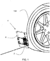
- the aerodynamic device 1 of the invention can be arranged, for example, in the wheel housing 100 of a vehicle.
- the wheel housing 100 of a vehicle is the portion of the chassis around the opening in which each of the wheels of said vehicle is arranged, as partially shown in Figure 1 .
- the aerodynamic device 1 of the invention can be arranged in other positions such as, for example, on the bumper, as a front spoiler.
- the aerodynamic device 1 of this embodiment is arranged in a wheel housing 100 of a vehicle and comprises a flap 2 movable between an extended position and a retracted position, and a casing 6 configured for housing the flap 2.
- the casing 6 is arranged facing the wheel housing and can be part of the chassis or a separate part fixed to the chassis.
- Extended position means that position in which part of the flap 2 projects from the wheel housing 100, positioned facing the wheel and opposing the air reaching it from the front part of the vehicle, as can be seen in Figures 1 , 2 , and 5 .
- This position allows improving vehicle aerodynamics and reducing fuel consumption, and therefore also reducing the contaminating emissions of the vehicle.
- the flap 2 should ideally be located in the extended position when the vehicle is traveling at high speeds.
- Retracted position means that position in which the flap 2 is housed inside the wheel housing 100 of the vehicle or minimally projects from said wheel housing 100, as can be seen in Figures 3 and 6 .
- the flap 2 should ideally be located in said retracted position when the vehicle is traveling at low speeds or over terrains with obstacles.
- extended position means that position in which the flap projects from the motor vehicle opposing to the air reaching it to improve its aerodynamics
- retracted position means that position in which the flap is housed inside or minimally projects from the motor vehicle.
- the aerodynamic device 1 of this embodiment also comprises an actuator 3 and a transmission mechanism 4 coupled to the actuator 3.
- the transmission mechanism 4 is configured for transmitting the movement of the actuator 3 to the flap 2.
- the flap 2 of the aerodynamic device 1 of the invention comprises a fixed portion 20 coupled to the transmission mechanism 4 and a mobile portion 21 coupled to the fixed portion 20 movable between two stable operation positions: a normal operation position and an emergency operation position.
- Normal operation position of the flap 2 refers to that in which the mobile portion 21 projects from the fixed portion 20, such that in the extended position of the flap 2 the mobile portion 21 projects from the wheel housing 100.
- Emergency operation position refers to that in which the mobile portion 21 is arranged fundamentally overlapping the fixed portion 20, such that even in the extended position of the flap 2, the mobile portion 21 is housed inside the wheel housing 100 of the vehicle or minimally projects from said wheel housing 100.
- the aerodynamic device 1 comprises an over-center spring 5 coupling both portions 20 and 21 exerting a force on the mobile portion 21 such that said mobile portion 21 is maintained in one of the two stable operation positions.
- the aerodynamic device of the invention is capable of preventing damage to the actuator and/or transmission mechanism in the event of an impact with a vertical force component, i.e., perpendicular to the movement of the vehicle, while at the same time keeping the flap in a stable position after sustaining the impact, which prevents annoying noises.
- over-center spring refers to a bistable spring which, when subjected to forces in one direction or the other, stores energy and releases it, being urged to one of the two equilibrium positions.
- the over-center spring comprises a force threshold such that if it is subjected to a force that is lower than the force threshold, it is urged to stay in the equilibrium position it is already in, and if the force threshold is exceeded, it changes the direction of the force of the over-center spring and urges the over-center spring to the other equilibrium position.
- the over-center spring 5 is a torsion helical spring comprising an elastic part arranged helically with two free ends 51 and 52 and several central coils 53, as can be seen in Figures 8 and 9 .
- One free end 51 of the over-center spring 5 is attached to the fixed portion 20 of the flap 2 and the other free end 52 of the over-center spring 5 is attached to the mobile portion 21 of the flap 2, the central coils 53 establishing the force threshold of the over-center spring 5.
- the over-center spring 5 is subjected to torsional forces in the clockwise direction exerting a separating force on the mobile portion 21 with respect to the fixed portion 20, i.e., the free end 52 attached to the mobile portion 21 is subjected to a clockwise torsional force pulling on the mobile portion 21 out of the casing 6, separating it from the fixed portion 20.
- the flap 2 is arranged in the extended position and the mobile portion 21 is arranged in this normal operation position, the mobile portion 21 projects from the casing 6, as can be seen in Figures 1 and 2 .
- the over-center spring 5 is subjected to torsional forces in the counterclockwise direction, exerting a pulling force on the mobile portion 21 with respect to the fixed portion 20, i.e., the free end 52 attached to the mobile portion 21 is subjected to a counterclockwise torsional force pulling on the mobile portion 21 into the casing 6, pulling it towards the fixed portion 20.
- the mobile portion 21 of the flap 2 is always housed for the most part inside the casing 6, as can be seen in Figures 6 and 7 .
- the over-center spring 5 allows the mobile portion 21 to move from one stable operation position to the other. That is, it allows relative movement between the fixed portion 20 and the mobile portion 21 of the flap 2 when an inverse force exceeding the force threshold of the over-center spring 5 is exerted on the mobile portion 21.
- the dynamic airflow loads on the mobile portion 21 of the flap 2 must not exceed the force threshold of the over-center spring, whereby the over-center spring 5 is configured so that its force threshold is minimally higher than said loads.
- the mobile portion 21 In the event of exceeding the force threshold, the mobile portion 21 would move from one stable operation position to the other. Said force threshold of the over-center spring 5 may be exceeded, for example, when, with the flap 2 in the extended position, the mobile portion 21 of the flap 2 has sustained an impact with a sufficient vertical force component towards the inside of the casing 6. Therefore, in the event of collision with obstacles which may be present during regular transit, such as curbs, garbage, blocks of ice, or even small animals, the mobile portion 21 of the flap 2 would move from the normal operation position to the emergency operation position if the vertical force component were to exceed the force threshold.
- obstacles which may be present during regular transit, such as curbs, garbage, blocks of ice, or even small animals
- the over-center spring 5 allows temporarily decoupling the synchronous movement of both portions 20, 21 of the flap 2, allowing relative movement between the fixed portion 20 and the mobile portion 21 of the flap 2, such that the over-center spring 5 absorbs the collision force and prevents said collision force from striking the actuator 3 and/or transmission mechanism 4 and damaging them.
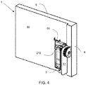
- the mobile portion 21 of the flap 2 moves to the emergency operation position shown in Figures 4 and 6 . Therefore, in this emergency position, the flap 2 is housed for the most part inside the casing 6.
- the mobile portion 21 comprises a stop 210 configured for cooperating with a reset stop 60 to return the mobile portion 21 to the normal operation position. That is, in the event that the mobile portion 21 has moved to the emergency operation position, as the flap 2 moves from the extended position to the retracted position, the stop 210 of the mobile portion 21 abuts with the reset stop 60 and the mobile portion 21 moves from the emergency operation position to the normal operation position. The flap 2 is thereby reset, adopting the normal operation position, as shown in Figures 3 and 7 .
- the reset stop 60 is arranged in the casing 6 configured for housing the flap 2.
- the reset stop could also be arranged at other fixed points of the low part of the motor vehicle such as the body or the bumper, provided that they may cooperate with the stop of the mobile portion.
- the casing 6, shown in Figures 2, 3 , 4 , and 5 comprises a main surface 63 parallel to the central surface 212 of the flap 2.
- the stop 210 associated with the mobile portion 21 extends past the main surface 63 of the casing 6, whereas the reset stop 60 of the casing 6 extends perpendicular to the main surface 63 of the casing 6.
- the flap 2 is introduced in the casing 6 as it moves from the extended position to the retracted position with the transmission mechanism 4.
- the fixed portion 20 of the flap 2 fundamentally carries out a linear movement between the retracted position and the extended position, just as the mobile portion 21 moves between the respective operation positions.
- the casing 6 comprises two fixing surfaces 61 and 62 which extend from the main surface 63 perpendicular thereto and which are parallel to one another, as shown in Figure 2 .
- the actuator 3 is arranged on a fixing surface 61 and the first portion 40 of the transmission mechanism 4 is arranged on the other fixing surface 62.
- the actuator 3 is a rotating actuator the output of which is coupled to the first portion 40 of the transmission mechanism 4, which in this case is a gear wheel 401 and the second portion 41 of the transmission mechanism is a rack with projections 411, the first portion 40 and the second portion 41 forming a rack and pinion mechanism, as shown in Figure 10 .
- the second portion 41 is arranged in the fixed portion 20 in the direction of the movement axis 402 and the first portion 40 is arranged with its axis of rotation 31 perpendicular to the movement axis 402.
- the fixed portion 20 of the flap 2 comprises a frame 201 the contour of which, with a lower segment 202 and an upper segment 203, delimits the movement of the mobile portion 21 on the fixed portion 20 between the normal operation position and the emergency position. Therefore, the stop 210 of the mobile portion 21 abuts with the lower segment 202 when the mobile portion 21 is arranged in the normal operation position, and abuts with the upper segment 203 of said frame 201 when the mobile portion 21 is arranged in the emergency position.
- the central area of the frame 201 is hollow in order to arrange the stop 210 in its central area.
- the over-center spring 5 is exerting a clockwise or counterclockwise torsional force on the mobile portion 21 which pushes the stop 210 of the mobile portion towards the lower segment 202 or the upper segment 203 of the frame 201.
- These segments 202 and 203 assure a fixing prestress between the fixed portion 20 and the mobile portion 21. Said prestress would assure stable fixing of the mobile portion 21 in either of the two operation positions without any degree of freedom or vibration between the portions 20 and 21 which result in annoying noises.
- the position of the stop 210 in the mobile portion 21 is defined so that this fixing prestress is lower than the force threshold of the over-center spring 5.
- the frame 201 of the fixed portion 20 of the flap 2 also comprises two side walls 204 and 204', in which there are arranged guiding means laterally guiding the flap 2 in its movement between the normal operation position and the emergency operation position.
- the guiding means are channels 205 in which the lateral ends 211 and 211' of the mobile portion 21 are at least partially housed, as shown in Figures 8 and 9 .
- the side walls 204 and 204' of the mobile portion 21 slide in the channels 205 of the fixed portion 20 to the emergency position in which the mobile portion 21 is for the most part housed between the channels 205 of the fixed portion 20, achieving a compact configuration of the aerodynamic device 1.
- the guiding means can be carried out in any manner known to one skilled in the art.
- the second portion 41 of the transmission mechanism 4 is arranged in one of the side walls 204, 204' of the frame 201.
- this arrangement of the second portion 41 is not intended to limit the present invention.
- the invention also relates to a motor vehicle comprising at least one aerodynamic device 1 such as the one described above.
Landscapes
- Engineering & Computer Science (AREA)
- Chemical & Material Sciences (AREA)
- Combustion & Propulsion (AREA)
- Transportation (AREA)
- Mechanical Engineering (AREA)
- Physics & Mathematics (AREA)
- Fluid Mechanics (AREA)
- Vibration Dampers (AREA)
Claims (8)
- Aerodynamische Vorrichtung für ein Kraftfahrzeug, umfassend- eine zwischen einer ausgefahrenen und einer eingefahrenen Position bewegliche Klappe (2),- ein rotierendes Stellglied (3) und- einen mit dem Stellglied (3) verbundenen Übertragungsmechanismus (4), der zur Übertragung der Bewegung des Stellglieds (3) auf die Klappe (2) ausgelegt ist, wobei die aerodynamische Vorrichtung (1) so ausgelegt ist, dass bei einem Stoß auf die Klappe (2), wenn sich die genannte Klappe (2) in der ausgefahrenen Position befindet, eine Beschädigung des Stellglieds (3) und/oder des Übertragungsmechanismus (4) verhindert wird,dadurch gekennzeichnet, dass- die Klappe (2) einen mit dem Übertragungsmechanismus (4) verbundenen feststehenden Bereich (20) und einen mit dem feststehenden Bereich (20) verbundenen beweglichen Bereich (21), welcher zwischen einer normalen Betriebsposition und einer Notbetriebsposition bewegbar ist, umfasst und- die aerodynamische Vorrichtung (1) eine Schnappfeder (5) umfasst, die den feststehenden Bereich (20) und den beweglichen Bereich (21) der Klappe (2) verbindet und auf den beweglichen Bereich (21) eine Kraft ausübt, sodass der genannte bewegliche Bereich (21) in einer der beiden Betriebspositionen gehalten wird,- die Schnappfeder (5) die Bewegung des beweglichen Bereichs (21) der Klappe (2) in die Notbetriebsposition ermöglicht, wenn der bewegliche Bereich (21) einen Stoß mit einer eine Kraftschwelle der Schnappfeder (5) überschreitenden vertikalen Kraftkomponente erhält.
- Aerodynamische Vorrichtung nach Anspruch 1, bei der der bewegliche Bereich (21) der Klappe (2) einen Anschlag (210) aufweist, der zum Zusammenwirken mit einem Rückstellanschlag (60) ausgelegt ist, sodass bei einer Bewegung der Klappe (2) von der ausgefahrenen Position in die eingefahrene Position nach erfolgter Bewegung des beweglichen Bereichs (21) in die Notbetriebsposition der Anschlag (210) des beweglichen Bereichs (21) an den Rückstellanschlag (60) anstößt und der Rückstellanschlag (60) den beweglichen Bereich (21) von der Notbetriebsposition in die normale Betriebsposition bewegt.
- Aerodynamische Vorrichtung nach Anspruch 2, die ein zur Aufnahme der Klappe (2) ausgelegtes Gehäuse (6) umfasst, wobei der Rückstellanschlag (60) in dem genannten Gehäuse (6) untergebracht ist.
- Aerodynamische Vorrichtung nach Anspruch 3, wobei das Stellglied (3) und ein Teil des Übertragungsmechanismus (4) auf dem Gehäuse (6) angeordnet sind und der andere Teil des Übertragungsmechanismus (4) auf dem feststehenden Bereich (20) der Klappe (2) angeordnet ist, sodass die Klappe bei ihrer Bewegung zusammen mit dem Übertragungsmechanismus (4) von der ausgefahrenen Position in die eingezogene Position in das Gehäuse (6) eingeschoben wird.
- Aerodynamische Vorrichtung nach einem der Ansprüche 2 bis 4, bei der der feststehende Bereich (20) einen Rahmen (201) aufweist, dessen Umrisse die Bewegung des beweglichen Bereichs (21) auf dem feststehenden Bereich (20) begrenzen, wobei der Anschlag (210) des beweglichen Bereichs (21) an ein unteres Segment des Rahmens (201) anstößt, wenn sich der bewegliche Bereich (21) in der normalen Betriebsposition befindet, und der genannte Anschlag (210) des beweglichen Bereichs (21) an ein oberes Segment des genannten Rahmens (201) anstößt, wenn sich der bewegliche Bereich (21) in der Notbetriebsposition befindet.
- Aerodynamische Vorrichtung nach Anspruch 5, wobei der Rahmen (201) Seitensegmente zur seitlichen Führung des beweglichen Bereichs (4) aufweist.
- Aerodynamische Vorrichtung nach Anspruch 6, bei der die Seitensegmente des Rahmens (201) Kanäle (205) zur Aufnahme der seitlichen Enden des beweglichen Bereichs (21) aufweisen.
- Kraftfahrzeug, dadurch gekennzeichnet, dass es mindestens eine aerodynamische Vorrichtung (1) nach einem der vorstehenden Ansprüche umfasst.
Priority Applications (1)
| Application Number | Priority Date | Filing Date | Title |
|---|---|---|---|
| EP19382062.8A EP3689719B1 (de) | 2019-01-30 | 2019-01-30 | Aerodynamische vorrichtung für ein kraftfahrzeug |
Applications Claiming Priority (1)
| Application Number | Priority Date | Filing Date | Title |
|---|---|---|---|
| EP19382062.8A EP3689719B1 (de) | 2019-01-30 | 2019-01-30 | Aerodynamische vorrichtung für ein kraftfahrzeug |
Publications (2)
| Publication Number | Publication Date |
|---|---|
| EP3689719A1 EP3689719A1 (de) | 2020-08-05 |
| EP3689719B1 true EP3689719B1 (de) | 2021-12-15 |
Family
ID=65529600
Family Applications (1)
| Application Number | Title | Priority Date | Filing Date |
|---|---|---|---|
| EP19382062.8A Active EP3689719B1 (de) | 2019-01-30 | 2019-01-30 | Aerodynamische vorrichtung für ein kraftfahrzeug |
Country Status (1)
| Country | Link |
|---|---|
| EP (1) | EP3689719B1 (de) |
Families Citing this family (1)
| Publication number | Priority date | Publication date | Assignee | Title |
|---|---|---|---|---|
| US12473036B2 (en) * | 2023-08-08 | 2025-11-18 | Toyota Motor Engineering & Manufacturing North America, Inc. | Vehicle tire guard device |
Family Cites Families (6)
| Publication number | Priority date | Publication date | Assignee | Title |
|---|---|---|---|---|
| FR2791630B1 (fr) * | 1999-04-01 | 2001-06-15 | Rehau Sa | Vehicule automobile a element aerodynamique escamotable |
| FR2897038B1 (fr) | 2006-02-06 | 2008-03-21 | Renault Sas | Dispositif aerodynamique pour vehicule |
| DE102006009681A1 (de) * | 2006-03-02 | 2007-09-06 | Bayerische Motoren Werke Ag | Fahrzeug mit einem Luftleitelement |
| KR101714252B1 (ko) * | 2015-10-30 | 2017-03-09 | 현대자동차주식회사 | 차량용 액티브 에어스커트 장치 |
| DE102016210407B4 (de) | 2016-06-13 | 2022-12-01 | Röchling Automotive SE & Co. KG | Frontspoiler-Anordnung mit als Überlastschutz vom Bewegungsantrieb entkoppelbarem Strömungsleitbauteil |
| FR3061124A1 (fr) * | 2016-12-22 | 2018-06-29 | Compagnie Plastic Omnium | Systeme aerodynamique retractable pour vehicule automobile. |
-
2019
- 2019-01-30 EP EP19382062.8A patent/EP3689719B1/de active Active
Also Published As
| Publication number | Publication date |
|---|---|
| EP3689719A1 (de) | 2020-08-05 |
Similar Documents
| Publication | Publication Date | Title |
|---|---|---|
| CN110937035B (zh) | 具有通过屈曲元件过载保护的可主动移位的车轮扰流板 | |
| EP1809530B1 (de) | Ein lenkgetriebe stützende frontstruktur für ein fahrzeug | |
| US20110172882A1 (en) | Collision mitigation system | |
| US11814113B2 (en) | Air deflection device in the underbody region of a motor vehicle and motor vehicle comprising such an air deflection device | |
| US9446795B2 (en) | Structure for reinforcing front vehicle body | |
| JP2000127991A (ja) | 衝撃吸収式ステアリング装置および自動車 | |
| US6676709B1 (en) | System for absorbing impacts in motor vehicles | |
| EP3689719B1 (de) | Aerodynamische vorrichtung für ein kraftfahrzeug | |
| CN119773878A (zh) | 车辆前部结构 | |
| JP6405731B2 (ja) | 車両のバッテリ保護構造 | |
| US7264301B2 (en) | Front structure of vehicle body | |
| US11569539B1 (en) | Impact screen | |
| CN205854068U (zh) | 主动预警反应式汽车保险杠 | |
| US8371628B2 (en) | Length-variable shock absorbing apparatus for vehicle | |
| CN214396658U (zh) | 一种主动式防撞梁、防撞系统及汽车 | |
| KR101875661B1 (ko) | 전방 차체 보강구조 | |
| KR101499447B1 (ko) | 차체 대쉬 밀림방지 구조 | |
| US9815497B1 (en) | Vehicles including an engine compartment spacer member | |
| US12054114B2 (en) | Retractable aerodynamic underbody flap with force absorption by the lower support | |
| JPH11342752A (ja) | 自動車用安全装置 | |
| JP4478035B2 (ja) | 車両用の可動式バンパ装置 | |
| KR100229267B1 (ko) | 자동차용 범퍼의 충격 흡수장치 | |
| CN223533291U (zh) | 作动器、作动组件、减震器、悬架系统及车辆 | |
| JP2009029151A (ja) | 車両のパワートレイン配設構造 | |
| JP5212617B2 (ja) | 車両の前部構造 |
Legal Events
| Date | Code | Title | Description |
|---|---|---|---|
| PUAI | Public reference made under article 153(3) epc to a published international application that has entered the european phase |
Free format text: ORIGINAL CODE: 0009012 |
|
| STAA | Information on the status of an ep patent application or granted ep patent |
Free format text: STATUS: THE APPLICATION HAS BEEN PUBLISHED |
|
| AK | Designated contracting states |
Kind code of ref document: A1 Designated state(s): AL AT BE BG CH CY CZ DE DK EE ES FI FR GB GR HR HU IE IS IT LI LT LU LV MC MK MT NL NO PL PT RO RS SE SI SK SM TR |
|
| AX | Request for extension of the european patent |
Extension state: BA ME |
|
| STAA | Information on the status of an ep patent application or granted ep patent |
Free format text: STATUS: REQUEST FOR EXAMINATION WAS MADE |
|
| 17P | Request for examination filed |
Effective date: 20210205 |
|
| RBV | Designated contracting states (corrected) |
Designated state(s): AL AT BE BG CH CY CZ DE DK EE ES FI FR GB GR HR HU IE IS IT LI LT LU LV MC MK MT NL NO PL PT RO RS SE SI SK SM TR |
|
| GRAP | Despatch of communication of intention to grant a patent |
Free format text: ORIGINAL CODE: EPIDOSNIGR1 |
|
| STAA | Information on the status of an ep patent application or granted ep patent |
Free format text: STATUS: GRANT OF PATENT IS INTENDED |
|
| INTG | Intention to grant announced |
Effective date: 20210728 |
|
| GRAJ | Information related to disapproval of communication of intention to grant by the applicant or resumption of examination proceedings by the epo deleted |
Free format text: ORIGINAL CODE: EPIDOSDIGR1 |
|
| GRAP | Despatch of communication of intention to grant a patent |
Free format text: ORIGINAL CODE: EPIDOSNIGR1 |
|
| INTG | Intention to grant announced |
Effective date: 20210910 |
|
| GRAS | Grant fee paid |
Free format text: ORIGINAL CODE: EPIDOSNIGR3 |
|
| GRAA | (expected) grant |
Free format text: ORIGINAL CODE: 0009210 |
|
| STAA | Information on the status of an ep patent application or granted ep patent |
Free format text: STATUS: THE PATENT HAS BEEN GRANTED |
|
| AK | Designated contracting states |
Kind code of ref document: B1 Designated state(s): AL AT BE BG CH CY CZ DE DK EE ES FI FR GB GR HR HU IE IS IT LI LT LU LV MC MK MT NL NO PL PT RO RS SE SI SK SM TR |
|
| REG | Reference to a national code |
Ref country code: GB Ref legal event code: FG4D Ref country code: CH Ref legal event code: EP |
|
| REG | Reference to a national code |
Ref country code: IE Ref legal event code: FG4D Ref country code: DE Ref legal event code: R096 Ref document number: 602019010087 Country of ref document: DE |
|
| REG | Reference to a national code |
Ref country code: AT Ref legal event code: REF Ref document number: 1455302 Country of ref document: AT Kind code of ref document: T Effective date: 20220115 |
|
| REG | Reference to a national code |
Ref country code: LT Ref legal event code: MG9D |
|
| REG | Reference to a national code |
Ref country code: NL Ref legal event code: MP Effective date: 20211215 |
|
| PG25 | Lapsed in a contracting state [announced via postgrant information from national office to epo] |
Ref country code: RS Free format text: LAPSE BECAUSE OF FAILURE TO SUBMIT A TRANSLATION OF THE DESCRIPTION OR TO PAY THE FEE WITHIN THE PRESCRIBED TIME-LIMIT Effective date: 20211215 Ref country code: LT Free format text: LAPSE BECAUSE OF FAILURE TO SUBMIT A TRANSLATION OF THE DESCRIPTION OR TO PAY THE FEE WITHIN THE PRESCRIBED TIME-LIMIT Effective date: 20211215 Ref country code: FI Free format text: LAPSE BECAUSE OF FAILURE TO SUBMIT A TRANSLATION OF THE DESCRIPTION OR TO PAY THE FEE WITHIN THE PRESCRIBED TIME-LIMIT Effective date: 20211215 Ref country code: BG Free format text: LAPSE BECAUSE OF FAILURE TO SUBMIT A TRANSLATION OF THE DESCRIPTION OR TO PAY THE FEE WITHIN THE PRESCRIBED TIME-LIMIT Effective date: 20220315 |
|
| REG | Reference to a national code |
Ref country code: AT Ref legal event code: MK05 Ref document number: 1455302 Country of ref document: AT Kind code of ref document: T Effective date: 20211215 |
|
| PG25 | Lapsed in a contracting state [announced via postgrant information from national office to epo] |
Ref country code: SE Free format text: LAPSE BECAUSE OF FAILURE TO SUBMIT A TRANSLATION OF THE DESCRIPTION OR TO PAY THE FEE WITHIN THE PRESCRIBED TIME-LIMIT Effective date: 20211215 Ref country code: NO Free format text: LAPSE BECAUSE OF FAILURE TO SUBMIT A TRANSLATION OF THE DESCRIPTION OR TO PAY THE FEE WITHIN THE PRESCRIBED TIME-LIMIT Effective date: 20220315 Ref country code: LV Free format text: LAPSE BECAUSE OF FAILURE TO SUBMIT A TRANSLATION OF THE DESCRIPTION OR TO PAY THE FEE WITHIN THE PRESCRIBED TIME-LIMIT Effective date: 20211215 Ref country code: HR Free format text: LAPSE BECAUSE OF FAILURE TO SUBMIT A TRANSLATION OF THE DESCRIPTION OR TO PAY THE FEE WITHIN THE PRESCRIBED TIME-LIMIT Effective date: 20211215 Ref country code: GR Free format text: LAPSE BECAUSE OF FAILURE TO SUBMIT A TRANSLATION OF THE DESCRIPTION OR TO PAY THE FEE WITHIN THE PRESCRIBED TIME-LIMIT Effective date: 20220316 |
|
| PG25 | Lapsed in a contracting state [announced via postgrant information from national office to epo] |
Ref country code: NL Free format text: LAPSE BECAUSE OF FAILURE TO SUBMIT A TRANSLATION OF THE DESCRIPTION OR TO PAY THE FEE WITHIN THE PRESCRIBED TIME-LIMIT Effective date: 20211215 |
|
| PG25 | Lapsed in a contracting state [announced via postgrant information from national office to epo] |
Ref country code: SM Free format text: LAPSE BECAUSE OF FAILURE TO SUBMIT A TRANSLATION OF THE DESCRIPTION OR TO PAY THE FEE WITHIN THE PRESCRIBED TIME-LIMIT Effective date: 20211215 Ref country code: SK Free format text: LAPSE BECAUSE OF FAILURE TO SUBMIT A TRANSLATION OF THE DESCRIPTION OR TO PAY THE FEE WITHIN THE PRESCRIBED TIME-LIMIT Effective date: 20211215 Ref country code: RO Free format text: LAPSE BECAUSE OF FAILURE TO SUBMIT A TRANSLATION OF THE DESCRIPTION OR TO PAY THE FEE WITHIN THE PRESCRIBED TIME-LIMIT Effective date: 20211215 Ref country code: PT Free format text: LAPSE BECAUSE OF FAILURE TO SUBMIT A TRANSLATION OF THE DESCRIPTION OR TO PAY THE FEE WITHIN THE PRESCRIBED TIME-LIMIT Effective date: 20220418 Ref country code: ES Free format text: LAPSE BECAUSE OF FAILURE TO SUBMIT A TRANSLATION OF THE DESCRIPTION OR TO PAY THE FEE WITHIN THE PRESCRIBED TIME-LIMIT Effective date: 20211215 Ref country code: EE Free format text: LAPSE BECAUSE OF FAILURE TO SUBMIT A TRANSLATION OF THE DESCRIPTION OR TO PAY THE FEE WITHIN THE PRESCRIBED TIME-LIMIT Effective date: 20211215 Ref country code: CZ Free format text: LAPSE BECAUSE OF FAILURE TO SUBMIT A TRANSLATION OF THE DESCRIPTION OR TO PAY THE FEE WITHIN THE PRESCRIBED TIME-LIMIT Effective date: 20211215 |
|
| PG25 | Lapsed in a contracting state [announced via postgrant information from national office to epo] |
Ref country code: PL Free format text: LAPSE BECAUSE OF FAILURE TO SUBMIT A TRANSLATION OF THE DESCRIPTION OR TO PAY THE FEE WITHIN THE PRESCRIBED TIME-LIMIT Effective date: 20211215 Ref country code: AT Free format text: LAPSE BECAUSE OF FAILURE TO SUBMIT A TRANSLATION OF THE DESCRIPTION OR TO PAY THE FEE WITHIN THE PRESCRIBED TIME-LIMIT Effective date: 20211215 |
|
| REG | Reference to a national code |
Ref country code: CH Ref legal event code: PL |
|
| REG | Reference to a national code |
Ref country code: DE Ref legal event code: R097 Ref document number: 602019010087 Country of ref document: DE |
|
| PG25 | Lapsed in a contracting state [announced via postgrant information from national office to epo] |
Ref country code: MC Free format text: LAPSE BECAUSE OF FAILURE TO SUBMIT A TRANSLATION OF THE DESCRIPTION OR TO PAY THE FEE WITHIN THE PRESCRIBED TIME-LIMIT Effective date: 20211215 Ref country code: IS Free format text: LAPSE BECAUSE OF FAILURE TO SUBMIT A TRANSLATION OF THE DESCRIPTION OR TO PAY THE FEE WITHIN THE PRESCRIBED TIME-LIMIT Effective date: 20220415 |
|
| REG | Reference to a national code |
Ref country code: BE Ref legal event code: MM Effective date: 20220131 |
|
| PLBE | No opposition filed within time limit |
Free format text: ORIGINAL CODE: 0009261 |
|
| STAA | Information on the status of an ep patent application or granted ep patent |
Free format text: STATUS: NO OPPOSITION FILED WITHIN TIME LIMIT |
|
| PG25 | Lapsed in a contracting state [announced via postgrant information from national office to epo] |
Ref country code: LU Free format text: LAPSE BECAUSE OF NON-PAYMENT OF DUE FEES Effective date: 20220130 Ref country code: DK Free format text: LAPSE BECAUSE OF FAILURE TO SUBMIT A TRANSLATION OF THE DESCRIPTION OR TO PAY THE FEE WITHIN THE PRESCRIBED TIME-LIMIT Effective date: 20211215 Ref country code: AL Free format text: LAPSE BECAUSE OF FAILURE TO SUBMIT A TRANSLATION OF THE DESCRIPTION OR TO PAY THE FEE WITHIN THE PRESCRIBED TIME-LIMIT Effective date: 20211215 |
|
| 26N | No opposition filed |
Effective date: 20220916 |
|
| PG25 | Lapsed in a contracting state [announced via postgrant information from national office to epo] |
Ref country code: SI Free format text: LAPSE BECAUSE OF FAILURE TO SUBMIT A TRANSLATION OF THE DESCRIPTION OR TO PAY THE FEE WITHIN THE PRESCRIBED TIME-LIMIT Effective date: 20211215 Ref country code: BE Free format text: LAPSE BECAUSE OF NON-PAYMENT OF DUE FEES Effective date: 20220131 |
|
| PG25 | Lapsed in a contracting state [announced via postgrant information from national office to epo] |
Ref country code: LI Free format text: LAPSE BECAUSE OF NON-PAYMENT OF DUE FEES Effective date: 20220131 Ref country code: FR Free format text: LAPSE BECAUSE OF NON-PAYMENT OF DUE FEES Effective date: 20220215 Ref country code: CH Free format text: LAPSE BECAUSE OF NON-PAYMENT OF DUE FEES Effective date: 20220131 |
|
| PG25 | Lapsed in a contracting state [announced via postgrant information from national office to epo] |
Ref country code: IE Free format text: LAPSE BECAUSE OF NON-PAYMENT OF DUE FEES Effective date: 20220130 |
|
| PG25 | Lapsed in a contracting state [announced via postgrant information from national office to epo] |
Ref country code: IT Free format text: LAPSE BECAUSE OF FAILURE TO SUBMIT A TRANSLATION OF THE DESCRIPTION OR TO PAY THE FEE WITHIN THE PRESCRIBED TIME-LIMIT Effective date: 20211215 |
|
| GBPC | Gb: european patent ceased through non-payment of renewal fee |
Effective date: 20230130 |
|
| PG25 | Lapsed in a contracting state [announced via postgrant information from national office to epo] |
Ref country code: GB Free format text: LAPSE BECAUSE OF NON-PAYMENT OF DUE FEES Effective date: 20230130 |
|
| PG25 | Lapsed in a contracting state [announced via postgrant information from national office to epo] |
Ref country code: MK Free format text: LAPSE BECAUSE OF FAILURE TO SUBMIT A TRANSLATION OF THE DESCRIPTION OR TO PAY THE FEE WITHIN THE PRESCRIBED TIME-LIMIT Effective date: 20211215 Ref country code: CY Free format text: LAPSE BECAUSE OF FAILURE TO SUBMIT A TRANSLATION OF THE DESCRIPTION OR TO PAY THE FEE WITHIN THE PRESCRIBED TIME-LIMIT Effective date: 20211215 |
|
| PG25 | Lapsed in a contracting state [announced via postgrant information from national office to epo] |
Ref country code: HU Free format text: LAPSE BECAUSE OF FAILURE TO SUBMIT A TRANSLATION OF THE DESCRIPTION OR TO PAY THE FEE WITHIN THE PRESCRIBED TIME-LIMIT; INVALID AB INITIO Effective date: 20190130 |
|
| PG25 | Lapsed in a contracting state [announced via postgrant information from national office to epo] |
Ref country code: MT Free format text: LAPSE BECAUSE OF FAILURE TO SUBMIT A TRANSLATION OF THE DESCRIPTION OR TO PAY THE FEE WITHIN THE PRESCRIBED TIME-LIMIT Effective date: 20211215 |
|
| PG25 | Lapsed in a contracting state [announced via postgrant information from national office to epo] |
Ref country code: TR Free format text: LAPSE BECAUSE OF FAILURE TO SUBMIT A TRANSLATION OF THE DESCRIPTION OR TO PAY THE FEE WITHIN THE PRESCRIBED TIME-LIMIT Effective date: 20211215 |
|
| PGFP | Annual fee paid to national office [announced via postgrant information from national office to epo] |
Ref country code: DE Payment date: 20260128 Year of fee payment: 8 |