EP3689730B1 - Systéme d'entraînement et véhicule - Google Patents
Systéme d'entraînement et véhicule Download PDFInfo
- Publication number
- EP3689730B1 EP3689730B1 EP20159575.8A EP20159575A EP3689730B1 EP 3689730 B1 EP3689730 B1 EP 3689730B1 EP 20159575 A EP20159575 A EP 20159575A EP 3689730 B1 EP3689730 B1 EP 3689730B1
- Authority
- EP
- European Patent Office
- Prior art keywords
- gear
- shift
- planetary
- drive
- drive arrangement
- Prior art date
- Legal status (The legal status is an assumption and is not a legal conclusion. Google has not performed a legal analysis and makes no representation as to the accuracy of the status listed.)
- Active
Links
Images




Classifications
-
- B—PERFORMING OPERATIONS; TRANSPORTING
- B62—LAND VEHICLES FOR TRAVELLING OTHERWISE THAN ON RAILS
- B62M—RIDER PROPULSION OF WHEELED VEHICLES OR SLEDGES; POWERED PROPULSION OF SLEDGES OR SINGLE-TRACK CYCLES; TRANSMISSIONS SPECIALLY ADAPTED FOR SUCH VEHICLES
- B62M6/00—Rider propulsion of wheeled vehicles with additional source of power, e.g. combustion engine or electric motor
- B62M6/40—Rider propelled cycles with auxiliary electric motor
- B62M6/55—Rider propelled cycles with auxiliary electric motor power-driven at crank shafts parts
-
- B—PERFORMING OPERATIONS; TRANSPORTING
- B62—LAND VEHICLES FOR TRAVELLING OTHERWISE THAN ON RAILS
- B62M—RIDER PROPULSION OF WHEELED VEHICLES OR SLEDGES; POWERED PROPULSION OF SLEDGES OR SINGLE-TRACK CYCLES; TRANSMISSIONS SPECIALLY ADAPTED FOR SUCH VEHICLES
- B62M11/00—Transmissions characterised by the use of interengaging toothed wheels or frictionally-engaging wheels
- B62M11/04—Transmissions characterised by the use of interengaging toothed wheels or frictionally-engaging wheels of changeable ratio
- B62M11/14—Transmissions characterised by the use of interengaging toothed wheels or frictionally-engaging wheels of changeable ratio with planetary gears
-
- B—PERFORMING OPERATIONS; TRANSPORTING
- B62—LAND VEHICLES FOR TRAVELLING OTHERWISE THAN ON RAILS
- B62M—RIDER PROPULSION OF WHEELED VEHICLES OR SLEDGES; POWERED PROPULSION OF SLEDGES OR SINGLE-TRACK CYCLES; TRANSMISSIONS SPECIALLY ADAPTED FOR SUCH VEHICLES
- B62M11/00—Transmissions characterised by the use of interengaging toothed wheels or frictionally-engaging wheels
- B62M11/04—Transmissions characterised by the use of interengaging toothed wheels or frictionally-engaging wheels of changeable ratio
- B62M11/14—Transmissions characterised by the use of interengaging toothed wheels or frictionally-engaging wheels of changeable ratio with planetary gears
- B62M11/145—Transmissions characterised by the use of interengaging toothed wheels or frictionally-engaging wheels of changeable ratio with planetary gears built in, or adjacent to, the bottom bracket
-
- B—PERFORMING OPERATIONS; TRANSPORTING
- B62—LAND VEHICLES FOR TRAVELLING OTHERWISE THAN ON RAILS
- B62M—RIDER PROPULSION OF WHEELED VEHICLES OR SLEDGES; POWERED PROPULSION OF SLEDGES OR SINGLE-TRACK CYCLES; TRANSMISSIONS SPECIALLY ADAPTED FOR SUCH VEHICLES
- B62M11/00—Transmissions characterised by the use of interengaging toothed wheels or frictionally-engaging wheels
- B62M11/04—Transmissions characterised by the use of interengaging toothed wheels or frictionally-engaging wheels of changeable ratio
- B62M11/14—Transmissions characterised by the use of interengaging toothed wheels or frictionally-engaging wheels of changeable ratio with planetary gears
- B62M11/18—Transmissions characterised by the use of interengaging toothed wheels or frictionally-engaging wheels of changeable ratio with planetary gears with a plurality of planetary gear units
Definitions
- the present invention relates to a drive assembly and a vehicle.
- the present invention relates in particular to a drive arrangement of a vehicle that can be driven with muscle power and/or - additionally - with motor power, an electric bicycle, e-bike, pedelec or the like, and a vehicle that can be driven with muscle power and/or - optionally additionally - with motor power, an electric bicycle, e-bike, pedelec or the like.
- Bicycles, electric bicycles and the like are often designed with a derailleur or hub gear system on the driven rear wheel.
- bottom bracket drives with an integrated manual transmission can also be provided.
- a generic drive arrangement is in the document DE 102 57 973 B3 shown.
- the drive arrangement according to the invention with the features of claim 1 has the advantage that with a comparatively small installation space in the area of the bottom bracket, the torque can be transmitted with a comparatively high degree of efficiency, i.e. with reduced losses, and also under load and thus without interruption of the tractive force can be done particularly small or even vanishing idle travel.
- a drive arrangement is created for a vehicle that can be driven with muscle power and/or - additionally - with engine power, in particular for an electric bicycle, e-bike, pedelec or the like, with a crankshaft that can rotate about an axis of rotation for receiving a first torque generated in particular with muscle power and with a transmission device which is used to transmit the first torque from the crankshaft to an output element that can be coupled to a drive wheel of the vehicle and by means of a - in particular automatically - switchable multi-stage planetary gear is designed to a variable translation.
- the translation of the planetary gear can be adjusted via a gear change and by controlled connection and/or release of respective sun gears of corresponding planetary stages via a driver element coupled in a torque-proof manner to the respective sun gear.
- the respective driver element is arranged radially and/or axially outside of at least the respectively coupled sun wheel with respect to the axis of rotation of the sun wheel.
- driver elements non-rotatably coupled to the respective sun gears outside of the respectively coupled sun gear enables a particularly reliable connection, blocking or locking and/or releasing or unlocking of the respective sun gears, because due to the off-axis arrangement of the driver elements and due to the resulting reduced forces at the same torque, particularly low failures and signs of wear can be expected.
- the respective driver element can also be formed radially inside but axially outside of the sun wheel with respect to the axis of rotation of the sun wheel.
- the driver elements can be within the radius of the sun gears, but spaced laterally therefrom, and still be located off-axis compared to the usual pawls or pull keys, with attendant advantages in terms of forces.
- the driver element is in each case formed on one or as a radially outer or outermost section of a shift finger coupled in a rotationally fixed manner to the respective sun gear.
- the structure of the driver element can be designed in a suitable manner, independently of the coupling to the sun gear, in order to carry out a gear change in a particularly reliable manner.
- Structurally particularly simple conditions arise when the respective shift finger is designed with a particularly ring-shaped base for non-rotatable coupling to the respective sun gear and a radial section extending essentially radially outwards from the base.
- the particularly ring-shaped base allows a particularly reliable non-rotatable coupling with the respective sun wheel, e.g. by a direct connection with it.
- claws for the realization of the driver elements allows different shapes to be introduced, (a) in order to prevent mutual interference between a plurality of driver elements and a corresponding plurality of sun gears and at the same time to enable a reliable gear change through controlled selective and/or combined locking and releasing and (b) to achieve a particularly compact construction or design of the drive unit in the axial direction. In this way it can be avoided that a provided shifting gate, depending on the selected gear, protrudes laterally far beyond a chainring as the driven element.
- a particularly uniform operation occurs when, according to another preferred development of the drive arrangement according to the invention, a radial section of a respective shift finger has or forms an elastic section which can be elastically deformed tangentially or in the circumferential direction in relation to the axis of rotation of the respective underlying sun gear in order to bring about a jerk-free or low-jerk movement of the underlying sun gear when the respective driver element hits or is released.
- driver elements are connected to a respective sun wheel via a mechanically self-switching freewheel, in particular in connection with a change in the direction of rotation of the associated sun wheels during a gear change and/or with the respective driver elements being held in both directions of rotation, in particular by an actuator, e.g. in the form of a shift gate.
- driver elements or shift fingers can therefore be connected to an associated sun gear via a mechanically self-switching freewheel.
- a coaxial arrangement of the multi-stage planetary gear to the axis of rotation and thus to the crankshaft is particularly space-saving and leads to a comparatively compact design.
- the compact design of the drive arrangement according to the invention in the sense of a bottom bracket gearbox can be alternatively or additionally increased by the planetary gear being designed coaxially with a rotationally symmetrical driven element, so that an arrangement results in which the driven element is designed as a rotationally symmetrical component coaxial to the axis of rotation of the crankshaft and to the planetary gear.
- the output element can preferably be designed as a chain wheel or toothed belt wheel, depending on the type of drive.
- a further development of the drive arrangement according to the invention has an increased number of gears and/or selectable transmission ratios, namely through the use of one or more freewheels, in particular for realizing a transmission ratio of 1:1, in a stepped planetary gear with a step-up transmission and/or in the overall transmission through a direct gear. It can be provided in particular that these translations are not actively switchable, but are designed to be mechanically self-switching.
- the planetary gear defines a plurality of gears, in particular with a number of seven gears, with gear jumps that are constant, amount to no more than about 26% on average and/or in individual cases are in the range of about 25% to about 27%, define a total spread of about 400% and/or are associated with an additional direct gear and the use of a freewheel, through which in a planetary gear with a Translation into the fast a sun with a planet carrier is connected.
- gear jumps that are constant, amount to no more than about 26% on average and/or in individual cases are in the range of about 25% to about 27%
- the gear shift stages are formed by (i) a first and in particular two-stage planetary gear with an overall step-up ratio and (ii) a second and in particular two-stage planetary gear connected in series therewith with an overall step-up ratio, in particular a planetary gear in the form of a stepped planetary gear, i.e. with planet wheels which have several stages which are connected to one another in a rotationally fixed manner.
- the gear shift stages can be preceded on the input side in particular (iii) by a booster stage with or in the form of a planetary gear with a step-up ratio for reducing a high driver torque.
- a booster stage with or in the form of a planetary gear with a step-up ratio for reducing a high driver torque.
- the two series-connected planetary gears of the gear shift stages can be coupled to one another via a common ring gear.
- this results in a particularly reliable gear change enables this to be carried out via an actuator by means of a shifting gate which is radially spaced apart from the axis of rotation of the crankshaft and/or the sun gears and can be positioned parallel to the axis in a controlled manner and has a plurality of stop elements for the driver elements.
- the present invention can be used not only in vehicles that are operated purely with muscle power, e.g. in classic bicycles, but in particular in electric bicycles, e-bikes, pedelecs or the like, as already mentioned at the beginning.
- an electric drive is designed to generate a motor torque and that the electric drive can be controllably coupled to the output element for transmitting the motor torque via the planetary gear.
- the electric drive has a hollow shaft motor with a hollow shaft on the output side.
- the hollow shaft motor as a whole or at least with its hollow shaft can be arranged and designed coaxially to the axis of rotation of the crankshaft, to the planetary gear, to the input-side planet carrier of the planetary gear and/or to a sun gear of a booster stage that may be provided.
- the hollow shaft of the hollow shaft motor can be coupled or can be coupled indirectly, for example via a motor reduction gear, or directly to the input-side planet carrier of the planetary gear and/or to the sun gear of a booster stage that may be provided, in particular in a controllable manner.
- the coupling of the electric drive and thus the transmission of the motor torque from the motor shaft to the planetary gear can be realized in different ways.
- a motor reduction gear is provided between the electric drive and the planetary gear, for example in the form of a multi-stage spur gear, a planetary gear or a stepped planetary gear, with a coaxial arrangement to the hollow shaft of the hollow-shaft motor, to the axis of rotation of the crankshaft, to the planetary gear, to the input-side planetary carrier of the planetary gear and/or to the sun gear of a booster stage that may be provided and/or in a form integrated in the hollow-shaft motor.
- a radially particularly compact design results if, according to an alternative drive arrangement that is not claimed, a motor reduction gear in the form of an evoloid gear is configured between the electric drive and the planetary gear. This can be designed with internal or external teeth.
- a drive arrangement which has the structure of a mid-engine drive and in particular comprises a common housing in which the planetary gear, the actuator, the electric drive, the motor reduction gear and—at least partially—the crankshaft are accommodated.
- the present invention also relates to a vehicle that can be driven with muscle power and/or—in addition—with engine power, and in particular an electric bicycle, e-bike, pedelec or the like.
- the vehicle according to the invention has at least one wheel and a drive arrangement designed according to the invention, with which at least one wheel of the vehicle can be driven.
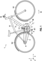
- an electric bicycle is described in detail as a preferred embodiment of the vehicle 1 according to the invention.
- the vehicle 1 includes as an electric bicycle a frame 12 on which a front wheel 9-1, a rear wheel 9-2 and a crank drive 2 with two cranks 7, 8 with Pedals 7-1 and 8-1 are arranged.
- An electric drive 3 is integrated into the crank mechanism 2 .
- a pinion 6 is arranged on the rear wheel 9-2.
- a drive torque which is provided by the driver and/or by the electric drive 3 , is transmitted from a chainring 4 on the crank mechanism 2 to the pinion 6 via a chain 5 .
- a control unit 10 is arranged on the handlebar of the vehicle 1, which is connected to the electric drive 3, which may be configured.
- a battery 11 is also formed in or on the frame 12 and is used to supply power to the electric drive 3 .
- a crank bearing 13 or bottom bracket which has a crankcase 14 and a crankshaft 15 , is integrated into the frame 12 .
- the drive arrangement 80 according to the invention of the vehicle 1 according to the invention figure 1 has the crank drive 2 and the electric drive 3, whereby the torques that can be generated by these are transmitted via a corresponding and in figure 1 Transmission device 20, not shown, can be accommodated with a switchable multi-stage planetary gear 21 and can be transmitted to the chain ring as an output element 4.
- figure 2 is a schematic plan view of an embodiment of the drive arrangement 80 according to the invention with an electric drive 3 and a crank mechanism 2.
- a transmission device 20 For the transmission of torques from the crank drive 2 and from the electric drive 3 , a transmission device 20 is designed, which has a planetary gear 21 arranged coaxially to the axis of rotation Y defined by the crankshaft 15 .
- the planetary gear 21 consists of a step-up driver 40 with a planetary gear 41 of the step-up driver 40 on the one hand and a multi-stage gearbox 50 with a first and here two-stage planetary gear 51, namely on the input side, facing the booster stage 40 and facing away from the output element 4, and a second and here two-stage Planetary gear 52, namely on the output side, facing the driven element 4 and facing away from the booster stage 40.
- the first and second planetary gears 51 and 52 of the manual transmission 50 have corresponding first and second sun gears 55 and 56 and the sun gears 55, 56 associated planet gears 57 and 58, which are mounted on planet carriers 22, 23 and coupled via a common ring gear 53.
- connection of the sun gears 55, 56 to the housing 14 of the drive arrangement 80 is effected in a controlled manner via detachable connections. This is done in the embodiment according to FIG figure 2 via the controlled, switchable locking or releasing of the rotating driver elements 64, which are connected to the sun gears 55, 56 in a rotationally fixed manner, on the distal ends 63-2 of the shift fingers 61 with the stop elements 68 on the link body 67 of the shift gate 66, which, in connection with the adjustment unit 60, which can also be referred to as an actuator 60, is at a distance from the axis of rotation Y but axis-parallel thereto in the direction of the arrow 95 is movable.
- Each of the sun gears 55 of the first planetary gear 51 and each of the sun gears 56 of the second planetary gear 52 of the gear shift stages 50 has its own shift finger 61 coupled to the respective sun gear 55, 56 in a torque-proof manner.
- the driver elements 64 which can also be referred to as claws or as driver claws and are located at the respective distal end 63-2 of the shift fingers 61, are arranged in relation to the gaps 69 and the stop elements 68, which can also be referred to as abutment elements or link claws, so that by moving the shift gate 66 in the direction of arrow 95, a separate or combined release or blocking of the individual sun gears 55 and 5 6 of the first and second planetary gears 51, 52 of the gear shift stages 50 of the manual transmission can be achieved.
- a freewheel 59 or 59-1 is formed at various points of the manual transmission 50, the freewheel 59-1 being associated with a direct gear.
- the booster stage 40 with the planetary gear 41 for introducing the torque generated with muscle power has a ring gear 42, an internal sun gear 43 and a planet carrier 45 running in between with planets 44 of the booster stage 40.
- the motor torque generated by the electric drive 3 is delivered through the motor shaft 31 to the motor reduction gear 30 and ultimately to a spur gear 35 as the output element of the motor reduction gear 30, which is materially connected to the input-side planetary carrier 22 of the manual transmission 50.
- the motor reduction gear 30 consists of an arrangement of a plurality of spur gears 32 to 34 which transmit the motor torque on the output side to the spur gear 35 coupled to the input-side planetary carrier 22 .
- FIGS. 3 and 4 show once again the embodiment of the drive arrangement 80 according to the invention from FIG figure 2 , but with the force, torque and power flows 101, 102 in relation to the driver and the engine power in a first gear and in the second to seventh gear of the arrangement figure 1 .
- the power flows of the engine are each denoted by reference number 101 and the power flows of the driver are denoted by reference number 102 .
- figure 5 shows another embodiment of the drive arrangement 80 according to the invention, in which the connection of the motor 3 with the reduction gear 30 is shifted axially to the left and thus outside the arrangement of the shift fingers 61 for both planetary gears 51, 52.
- figure 6 shows a side view of another embodiment of the drive arrangement 80 according to the invention, specifically with a viewing direction perpendicular to the y-direction.
- the axis of rotation Y associated with the crankshaft 15 can be seen, about which the output element 4 in the form of a chainring, the manual transmission 50 with the corresponding ones are arranged coaxially Gear shift stages and the first and second planetary gears 51 and 52 and the booster stage 40. Also visible are the shift fingers 61, which are non-rotatably connected to the sun gears 55 and 56, with the driver elements 64 at their distal ends 63-2.
- the further coupling of the first and second planetary gears 51 and 52 takes place via the common ring gear 53.
- the introduction of a motor torque takes place via the spur gear 35, which is also provided coaxially, as the output element of the motor reduction gear 30.
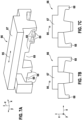
- FIGS 7A to 7C show in a perspective side view and in lateral top views the shifting gate 66 used in an embodiment of the drive arrangement 80 according to the invention with a gate body 67 and sequences of stop elements 68 formed thereon with gaps 69 provided between them fixedly coupled to the sun gears 55, 56 of the planetary gears 51, 52 shift fingers 61 with the driver elements 64 at their distal ends 63-2.
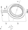
- figure 8 shows a perspective side view of a shift finger 61, as can be used in connection with the adjustment unit 60 of an embodiment of the drive arrangement 80 according to the invention.
- the shift finger 61 consists according to figure 8 an annular base 62, from which a radial section 63 of a certain length arises radially. This means that the radial section 63 is attached to the base 62 with its proximal end 63 - 1 .
- the distal end 63 - 2 which forms a driver element 64 , is arranged opposite the proximal end 63 - 1 .
- the area between the proximal end 63-1 and the distal end 63-2 is in the embodiment according to FIG figure 8 formed by an elastic section 65, which allows a resilient movement of the shift finger 61 in the tangential or circumferential direction when entering or releasing a stop of the shift finger 61. This enables a low-jerk or jerk-free coupling and decoupling of a sun wheel 55, 56 when changing gears.
- figure 9 shows a side view of another embodiment of the drive arrangement 80 according to the invention with a focus on the actuating drive 60, which can also be referred to as an adjustment unit and is used to move the switching link 66.
- the gearbox 50 is shown with the gear shift stages, which are realized by a first planetary gear 51 and a second planetary gear 52 with a common ring gear 53 .
- the step-up driver stage 40 is formed on the input side.
- the driven element 4 On the output side is the driven element 4 in the form of a chainring.
- the gear 35 of the spur gear stage of the motor reduction gear 30 for inputting the motor torque is shown.
- the high driver level 40 with the corresponding planetary gear 41, the gear wheel 35 of the frontal wheel level of the motor-reducing gear 30, the gearbox levels 50 with the first and second planetary gear 51 and 52, the switching finger 61 with the drain elements 64 at their distal ends 63-2 and the output element 4 are concentrically and koaxial in relation to the axle of rotation.
- the shift gate 66 of the adjustment unit 60 has, on the side facing the manual transmission 50 , a sequence of stop elements 68 on the link body 67 with gaps 69 provided in between.
- the stop elements 68 and the gaps 69 are designed and arranged in such a way that by moving the link body 67 along the displacement direction 95, here parallel to the axis of rotation Y of the crankshaft 15, the driver elements 64 of the sun gears of the first and second planetary gears 51, 52 can be selectively released or locked individually or in combination with one another in their rotation with the sun gears 55, 56.
- the movement of the gate body 67 of the shifting gate 66 takes place along the direction of the arrow 95 via a drive with motor 90, planetary gear 91, spur gear 92, attached thereto spindle 93 and a spindle nut engaging with the spindle 93 94, on which a saddle 96 is attached in the manner of a plain bearing for guiding the shift gate 66.
- the spindle 93 is rotated and the spindle nut 94 is carried along accordingly, the shifting of the link body 67 in the direction of the displacement arrow 95.
- the operation of the motor 90 and thus the shifting of the link body 67 can be carried out in a controlled manner by evaluating signals from a sensor system, not shown here, so that a collision during the movement of the stop elements 68, which also acts as a link claw en are referred to, and the rotating shift finger 61 is avoided with the driver elements 64 in the y-direction.
- figure 10 shows a side view of another embodiment of the drive arrangement 80 according to the invention with a focus on the electric drive 3 and its motor reduction gear 30.
- the motor 3 is located in the core to inside a motor housing 39.
- figure 11 shows a sectional view of another embodiment of the drive assembly 80 according to the invention.
- the motor reduction gear 30 also consists of an evoloid gear 37 with an evoloid pinion 36 on the motor shaft 31, which meshes with the evoloid gear 37.
- the electric drive 3 is housed with its essential components of the motor reduction gear 30 in a housing 39, which in turn is mounted on the bottom bracket housing 14 or forms part of it.
- sealing rings in connection with the storage of the crankshaft 15 in the housing 14 are also shown.
- the electric drive 3 in the embodiment of the drive assembly 80 according to the invention figure 11 still has the special feature of a freewheel 75 and freewheels 76, which are already shown schematically in figure 2 are shown and themselves have no integrated storage.
- the bearings 77 and other bearings of the drive assembly 80 are also shown, as well as the connections 54 between the shift fingers 61 and the corresponding sun gears 55, 56.
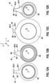
- figure 12 shows a side view of various embodiments of the shift fingers 61, which can be used in one embodiment of the drive assembly 80 according to the invention, for example as the four shift fingers from FIGS figures 6 , 9 and 10 .
- the different configurations relate to the shape of the respective bases 62 and the length and thickness of the radial sections 63 adjoining them with their proximal ends 63-1 and also to the configuration of the driver elements 64 at the distal ends 63-2 of the radial sections 63.
- the configurations are each adapted in such a way that the switching fingers 61 overlap, e.g can take place at the distal end 63-2 without mutual collision and in order to achieve a particularly compact construction/design of the drive unit in the axial direction, the shifting gate 66, for example, otherwise depending on the gear selected, would protrude laterally far beyond the chainring 4.
- the invention relates in particular to electric bicycles, pedelecs, e-bikes and the like, in particular with a central motor drive and a bicycle gear system for adapting the driver's limited driving force to the different driving resistances.
- One objective of the invention is to create a bicycle gearshift, e.g. based on the basic principle of a hub gearshift, and to integrate this into a drive arrangement 80 on the bottom bracket 13, e.g. of a pedelec or the like.
- a conventional switching device on the rear wheel 9-2 can then be omitted according to the invention.
- a particularly compact configuration of a drive arrangement 80 with a high level of efficiency is to be achieved, which is capable of shifting under load, allows shifting without an interruption in traction and manages without or with a reduced amount of idle travel.
- a friction ring gear as an infinitely variable bicycle transmission in a pedelec/eBike bottom bracket drive
- a friction ring transmission has the disadvantage of a comparatively lower level of efficiency, which affects the battery range and drivability without motor support, especially when driving at over 25 km/h with pedelecs.
- bottom bracket drives with integrated circuits based on spur gears have the disadvantage of a comparatively lower torque density. Also, they cannot be shifted under load or can only be shifted under part load, especially when shifting down to a lower gear. Furthermore, these circuits do not have an electromechanically actuated automatic gear selection.
- shifting takes place by holding or releasing gears by means of pawls, which are arranged around the central shaft of the gears and positively engage radially from the inside in the wheel body.
- the invention also has the task, for example, of creating an efficient automatic bicycle transmission that is capable of power shifting and has no interruptions in traction, and to integrate it into a drive unit 80 on the bottom bracket 13 of a pedelec.
- a switching device on the rear wheel 9-2 can be omitted.
- a particularly compact representation of the pedelec drive is to be achieved.
- the invention solves the task, among other things, with the use and integration of a switchable planetary gear 21 in a coaxial arrangement with the pedal crankshaft 15 and chainring 4.
- the switchable planetary gear 21 assumes the task of the bicycle gearshift or the variable translation for the driving force of the driver.
- the translation or switching is varied by blocking or releasing sun gears 55, 56 of a gearbox 50 of the planetary gear 21.
- the use of a positive-locking gear improves the efficiency compared to an integrated friction-locking gear.
- shift fingers 61 are attached to the side, which are rotatably connected to the sun gears 55, 56 and rotate with them.
- Varying the gear ratio or shifting under maximum load, even when shifting down the gears in a particularly critical manner, is thus possible without wear and while maintaining a compact representation of the gears.
- the structure of the shift finger 61 is designed to be elastic, e.g. by an elastic area 65 on or in the radial section 63.
- the shift finger 61 endures the maximum braking torque that occurs on the sun gear 55, 56 without plastic material deformation.
- One or more shift fingers 61 can be connected to the sun gear 55, 56 via a mechanically self-shifting freewheel. This makes it possible to avoid idle travel of the pedal cranks 7, 8 without power transmission during all switching operations.
- the shift gate 66 in combination with the freewheel can be used to prevent the shift fingers 61 from rotating away from the shift gate 66 when the direction of rotation of the associated sun gears 55, 56 changes, so that when the sun gears 55, 56 are blocked, there is no idle travel of the pedal cranks 7, 8 without power transmission due to the rotation time of the shift finger 61 to the position of the shift gate.
- the shifting gate 66 for blocking the shift finger 61 can be done automatically by an electric motor 90 with a gear 91, 92 as an actuator.
- the rotational position of the shift finger 61 is detected by means of a sensor and the point in time at which the shift gate 66 is shifted is thus controlled. This ensures that the shift gate 66 is fully in the correct position when the shift finger 61 reaches the shift gate 66 position. In this way, misalignments and edge loads are avoided.
- a particularly compact representation with high efficiency and a high number of shift stages or shiftable gears is achieved by realizing the switchable planetary gear 50 as a double stepped planetary gear with planetary gears 51 and 52 with connection of the two stepped planetary gears 51, 52 via a common ring gear 53 and a booster stage 40 upstream of the switchable planetary gear 50, which reduces the high torque of the driver.
- the stepped planetary gear 55 facing the input torque of the driver increases the gear ratio and the second stepped planetary gear 56 facing the chain ring 4 reduces the gear ratio.
- two shafts can be connected to one another by a self-shifting freewheel, and the ratio 1:1 in this stepped planetary gear 55 can also be realized in a simple manner.
- Another gear is obtained in a compact manner by connecting the pedal crankshaft 15 to the planet carrier 23 of the stepped planetary gear 56, which translates into a slower speed, via a freewheel 59-1.
- the freewheel 59-1 automatically connects the pedal crankshaft 15 to the planet carrier 23 and thus also directly to the chainring 4.
- a motor 3 can optionally be connected to the manual transmission 50 arranged coaxially with the pedal crankshaft 15 and the chain ring 4 via a reduction gear 30 , preferably between the booster stage 40 and the planetary manual transmission 50 .
- figure 1 shows, in a preferred embodiment, the structure of a Pedelec/eBike bottom bracket drive 80 with an integrated, power-shiftable planetary gear 50 in a coaxial arrangement with the crankshaft 15 and chain ring 4.
- the switchable planetary gear 50 consists of two stepped planetary gears 51, 52, each with a stepped planet 57, 58, which consists of two non-rotatably connected planets with different diameters. Both stepped planetary gears 51, 52 are connected to one another via a common ring gear 53.
- the stepped planetary gear 56 facing the chain ring 4 downshifts and the stepped planetary gear 55 facing the booster stage 40 on the left side next to the stepped planetary gear 56 translates up.
- the sun gears 55, 56 can be blocked in their rotational movement or connected non-rotatably to the housing 14 and released again individually or in combination by means of a shift gate 66.
- the translation 1:1 can also be realized in this step planetary gear 50 .
- a total of six translations can then be displayed.
- the pedal crankshaft 15 can be connected to the planetary carrier 23 of the stepped planetary gearing 56 on the right-hand side, reducing the speed, and thus directly to the chain ring 4 via a further freewheel.
- the following table lists the seven gears implemented in the preferred embodiment.
- the gear ratios range from gear ratio 1 in first gear, the direct gear, to gear ratio 0.25 in seventh gear.
- the result is a total spread of 400% and gear jumps of around 26% on average. This covers a required development of 2 m to 8 m for standard wheels.
- a total of seven gears with four manual transmission stages 50 can be represented in this example in a particularly compact manner.
- the manual transmission stages 50 are preferably designed in such a way that the gear steps are constant and, for example, not greater than 25% to 27%, as is listed in the table below.
- figure 2 shows that two of the four shift fingers 61 are each connected to the associated sun gear 55, 56 via a self-shifting overrunning clutch 59. It is thus possible to prevent the shift finger 61 from rotating away from the shift gate 66 during a gear change after the shift finger 61 has been blocked by the shift gate 66 .
- the shift finger 61 can be held in the blocking position by means of the shift gate 66 and at the same time the sun gear 55, 56 can be released again for a gear change. This takes place in that, during a gear change, the sun gear 55, 56 undergoes a reversal of direction of rotation and at the same time the freewheel 59 decouples the shift finger 61 from the associated sun gear 55, 56.
- a shift gate 66 is shown for actively varying the translation or shifting the gears.
- the shift gate 66 can be displaced parallel to the direction of the crankshaft axis Y, namely in the direction of the double arrow 95. By moving the shift gate 66, the shift fingers 61 and thus the sun gears 55, 56 can be blocked individually or in combination in both directions of rotation by the claws 68 of the shift gate 66.
- the shifting gate 66 is designed in such a way that the gears are always shifted through in sequence in both directions, i.e. when shifting up and down, without skipping gears.
- the position, distances and dimensioning of the claws 68 are selected in such a way that, according to the shifting logic or according to the gear ratio scheme and the required shifting speed, the shift fingers 61 involved in a specific gear ratio can be blocked or released.
- the edges of the claws are rounded to minimize edge wear.
- the claws are arranged in such a way that the shift fingers 61 in question are encompassed and thus blocked in both directions of rotation, as is shown in figure 7 is explained.
- the gear ratio can be varied or shifted without wear under maximum load even with high torque density due to a high maximum torque of the rider and the compact dimensions of a bicycle drive 80.
- the shift fingers 61 can be provided with an elastic structure 65. This serves to reduce a shift shock when the shift finger 61 or the sun gear 55, 56 is blocked.
- the shift finger 61 or the elastic structure 65 endure the maximum braking torque that occurs on the sun gear 55, 56 without plastic material deformation.
- figure 9 shows a preferred embodiment of a device for automated shifting of the shift gate 66 by an electric motor 90 with gear 91, 92 in the manner of an actuator 60.
- the gear consists of a planetary gear 91 for reducing the engine speed, a spur gear 92 for the transition to an intermediate shaft and a spindle 93, which is attached to the intermediate shaft.
- the spindle nut 94 is positively connected to the shift gate 66, which is axially displaceably mounted on the housing 14 in a sliding manner.
- the rotational position of the shift finger 61 is detected by a sensor as it rotates, in order to control the point in time at which the shift gate is shifted. This ensures that the shift gate is completely in the correct blocking position for the selected gear when the corresponding shift finger 61 reaches the position of the shift gate 66 .
- the high driver torque is reduced by a planetary gearbox 50 upstream of the planetary gear 41 as a booster stage 40 with a step-up ratio, as can be seen from FIGS figures 2 and 6 is evident.
- the planet carrier 45 of the booster stage 40 is the drive or input element of the booster stage 40 and is directly connected to the pedal crankshaft 15 in a rotationally fixed manner.
- the driven or output element of the booster stage 40 is the sun gear 43, which is connected to the planet carrier 22 of the left-hand stepped planetary gear 51 with a step-up ratio.
- the ring gear 42 of the step-up driver is firmly connected to the housing 14 .
- the figures 2 , 6 and 10 show in a preferred embodiment the connection of a motor 3 to support the driver's performance to the manual transmission 50.
- the motor 3 is connected via a reduction gear 30 to the planet carrier 22 of the left-hand stepped planetary gear with a step-up ratio.
- the planet carrier 22 forms part of the wheel body of the output gear 35 of the motor reduction gear 30 and is thus integrated into the motor gear 30 . This results in a particularly compact design of the bottom bracket drive 80.
- driver torque and engine torque are summed at planetary carrier 22 .
- driver and engine torque are summed at the pedal crankshaft 15.
- the Figures 3 and 4 show the different power flow 101, 102 of driver and engine power in first gear and in second to seventh gear.
- the motor reduction gear 30 consists of a two-stage spur gear, the gear stage close to the motor being designed as a particularly compact evoloid gear with a pinion 36 on the motor shaft 31 with five teeth.
- a freewheel 75 is arranged on the intermediate shaft of the motor transmission.
- the freewheel 75 is an overrunning clutch and is used to decouple the engine 3 in a case where the driver "overtakes" the engine, i.e. for example if the engine fails or at speeds above 25 km/h.
- FIG 5 an alternative arrangement of the motor 3 to the planet carrier 22 of the left-hand stepped planetary gear with step-up with a two-stage spur gear as a reduction gear 30 is shown.
- the motor reduction gear 30 By arranging the motor reduction gear 30 between the booster stage 40 and the planetary gearbox 50, the motor reduction gear 30 also uses the translation of the booster stage 40 and can thus be designed more compactly by the reduction of the motor reduction gear 30 reduced by the translation of the booster stage 40.
- FIG. 1 shows the implementation of the invention with storage and parts of the housing structure.
- a particularly compact representation of the axial installation space of the bottom bracket drive 80 results from the axially offset shaft connections of the planet carrier 45 and the sun wheel 43 of the booster stage 40.
- the electric drive 3 has a hollow shaft motor with a hollow shaft on the output side.
- the hollow shaft motor as a whole or at least with its hollow shaft can be arranged and designed coaxially to the axis of rotation Y of the crankshaft 15, to the planetary gear 21, to the input-side planet carrier 22 of the planetary gear 21 and/or to the sun gear 43 of a booster stage 40 that may be provided.
- the hollow shaft of the hollow shaft motor of the electric drive 3 can be coupled or can be coupled indirectly, for example via a motor reduction gear 30, or directly to the input-side planet carrier 22 of the planetary gear 21 and/or to the sun gear 43 of a step-up stage 40 that may be provided, in particular in a controllable manner.
- the invention also has the object of converting an electric drive 3 and in particular a related motor to support the driver in a particularly suitable manner into a load-shiftable, to integrate a traction force interruption-free and efficient automatic transmission of a drive unit 80 on the bottom bracket of a pedelec 1.
- the hollow shaft motor, motor electronics, planetary gearbox 21, 50, pedal crankshaft 15 and chain ring 4 are arranged coaxially.
- the power-shiftable planetary gear 20 is constructed according to the principle described above and has the corresponding advantages, taking on the task of a bicycle gearshift or a variable transmission ratio for the driver's driving force.
- the gear ratio is varied and/or the gear shifted by blocking or releasing the sun gears 55, 56.
- shift fingers 61 are attached to the sides of the sun gears 55, 56 of the planetary gear 21, 50, which are non-rotatably connected to the sun gears 55, 56 and rotate with them.
- a shift gate 66 which is arranged axially parallel to the pedal crankshaft 15 and can be displaced axially in the direction of the crankshaft axis Y, for example with an electric motor, the shift fingers 61 and thus the sun gears 55, 56 can be blocked individually or in combination in both directions of rotation.
- the rotor of a hollow shaft motor 3 is connected either directly or preferably via a motor reduction gear 30 to a rotating input element 22 of the planetary gearbox 21, 50.
- the stator is connected to the housing 14 together with the electronics.
- a hollow-shaft motor can preferably be arranged between a step-up driver stage 40, which is arranged in front of the planetary gearbox 21, 50 in order to reduce the driver's torque, and the planetary gearbox 21, 50.
- the motor-reduction gear 30 thus also uses the translation of the booster stage 40 and can be designed to be correspondingly more compact. Alternatively, the motor 3 can also be designed to be more compact.
- the hollow-shaft motor 3 also assumes the function of the actuating drive 60 or the actuator for the shifting mechanism of the planetary shifting gear 21, 50. This is done by connecting the hollow-shaft motor 3 via a shiftable gear and spindle drive to the shifting mechanism, in particular with a shift gate 66.
- a hollow shaft motor is designed for the motor drive 3 in the other embodiments.
- the hollow shaft motor is arranged coaxially to the pedal crankshaft 15 and to the chainring 4 between the shift fingers 61 and the step planetary gear 51, 52 of the planetary shift gear 21, 50.
- the hollow shaft of the rotor of the hollow shaft motor can be connected directly to the planet carrier 22 of the stepped planetary gear 51, 52 of the planetary shift gear 21, 50.
- the stator and the motor electronics of the hollow shaft motor can be connected to the housing 14 .
- the connections of the shift fingers 61 with the associated sun gears 55, 56 can run inside the hollow shaft of the hollow shaft motor and through the hollow shaft.
- the freewheel 59 connected to a shift finger and another freewheel, which can connect the planet carrier 22, 23 to a sun gear 55, 56, can also be arranged within the hollow shaft of the hollow shaft motor.
- the rotor of a hollow-shaft motor can be connected to the planet carrier 22 of the planetary gearbox 21, 50 via a planetary gear, in particular a stepped planetary gear, as a motor reduction gear.
- a freewheel between the hollow shaft of the hollow shaft motor and the sun gear of the motor reduction gear can decouple the motor from the driver's drive train when the motor is at a standstill in order to avoid an efficiency that is unfavorable for the driver due to the motor being towed.
- the planetary gear of the motor can also use the shafts of the planets 57, 58 of the planetary gearbox 21, 50 with the same center distance.
- the arrangement of a hollow shaft motor with a motor reduction gear between the booster stage and an outer part of the shift fingers 61 is implemented.
- An engine freewheel for decoupling the engine when the engine is at a standstill can be arranged between the planetary carrier as the output element of the motor reduction gear and the planetary carrier 22, 23 as the drive element of the planetary gearbox 21, 50.
- An alternative connection of a hollow shaft motor can be done via a two-stage spur gear as a motor reduction gear to the planetary carrier 22 of the planetary gearbox 21, 50.
- the hollow shaft motor can be connected to a shift gate 66 via a shiftable gear and spindle drive.
- the hollow shaft motor also assumes the function of an actuator 60 for the automatic shift mechanism of the planetary gearbox 21, 50, in particular for the automatic adjustment of the shift gate 66.
- a hollow-shaft motor with a direct connection to the planet carrier 22 of the planetary gearbox 21, 50 is also conceivable, i.e. without a motor reduction gear.
Landscapes
- Engineering & Computer Science (AREA)
- Chemical & Material Sciences (AREA)
- Combustion & Propulsion (AREA)
- Transportation (AREA)
- Mechanical Engineering (AREA)
- Structure Of Transmissions (AREA)
- Transmission Devices (AREA)
Claims (9)
- Système d'entraînement (80) pour un véhicule (1) pouvant être entraîné par une force musculaire et/ou en plus par une force de moteur, un vélo électrique, un eBike, un Pedelec ou similaire,
comprenant :- un vilebrequin (15) pouvant tourner autour d'un axe de rotation (Y) pour recevoir un premier couple généré notamment avec une force musculaire et- un dispositif de transmission (20) qui est réalisé de manière à transmettre le premier couple depuis le vilebrequin (15) à un élément de prise de force (4) pouvant être accouplé à une roue d'entraînement (9-2) du véhicule (1) et au moyen d'un engrenage planétaire (21) à plusieurs étages, commutable, notamment automatiquement, en vue d'une transmission variable, dans lequel :- la transmission de l'engrenage planétaire (21) peut être ajustée par le biais d'un changement de vitesses et par une connexion et/ou une libération commandées de roues solaires respectives (55, 56) d'étages planétaires correspondants (57, 58) par le biais d'un élément d'entraînement (64) accouplé de manière solidaire en rotation à la roue solaire respective (55, 56), et- l'élément d'entraînement respectif (64) est disposé radialement et/ou axialement à l'extérieur de la roue solaire respectivement accouplée (55, 56),caractérisé en ce qu'un changement de vitesses peut être effectué par le biais d'un entraînement de commande (60), au moyen d'une coulisse de changement de vitesses (66) espacée radialement par rapport à l'axe de rotation (Y) du vilebrequin (15) et/ou des roues solaires (55, 56) et pouvant être positionnée de manière commandée avec son axe parallèle, ayant une pluralité d'éléments de butée (68) pour les éléments d'entraînement (64). - Système d'entraînement (80) selon la revendication 1,
dans lequel l'élément d'entraînement (64) est réalisé respectivement au niveau d'une, ou sous forme d'une, portion située radialement à l'extérieur ou la plus extérieure d'un doigt de changement de vitesses (61) accouplé de manière solidaire en rotation à la roue solaire respective (55, 56). - Système d'entraînement (80) selon la revendication 2,
dans lequel le doigt de changement de vitesses respectif (61) est réalisé avec une base (62), notamment de forme annulaire, pour l'accouplement solidaire en rotation à la roue solaire respective (55, 56) et avec une portion radiale (63) s'étendant essentiellement radialement vers l'extérieur depuis la base (62), dont l'extrémité distale (63-2) opposée à la base (62) présente ou forme l'élément d'entraînement respectif (64), notamment sous la forme d'une griffe. - Système d'entraînement (80) selon la revendication 3,
dans lequel une portion radiale (63) d'un doigt de changement de vitesses respectif (61) présente ou forme une portion élastique (65) qui peut être déformée tangentiellement ou élastiquement dans la direction périphérique par rapport à l'axe de rotation (Y) de la roue solaire (55, 56) sous-jacente respectivement, afin de provoquer un mouvement sans à-coups ou à faibles à-coups de la roue solaire (55, 56) sous-jacente dans le cas d'une venue en butée ou d'une libération de l'élément d'entraînement respectif (64). - Système d'entraînement (80) selon l'une quelconque des revendications précédentes,
dans lequel plusieurs éléments d'entraînement (64) sont reliés à une roue solaire (55, 56) respective par le biais d'une roue libre (59) à commutation automatique mécaniquement, en particulier en rapport avec un changement de sens de rotation des roues solaires (55, 56) associées en cas de changement de vitesses et/ou avec une fixation des éléments d'entraînement (64) respectifs dans les deux sens de rotation, en particulier au moyen d'un entraînement de commande (60), par exemple sous la forme d'une coulisse de changement de vitesses (66). - Système d'entraînement (80) selon l'une quelconque des revendications précédentes,
dans lequel:- l'engrenage planétaire commutable (21), à plusieurs étages, est réalisé essentiellement coaxialement par rapport à l'axe de rotation (Y) du vilebrequin (15) et/ou- l'élément de prise de force (4) est réalisé avec une symétrie de révolution et coaxialement par rapport à l'axe de rotation (Y) du vilebrequin (15) et par rapport à l'engrenage planétaire (21) et notamment est ou présente un plateau de chaîne ou un plateau de courroie dentée. - Système d'entraînement (80) selon l'une quelconque des revendications précédentes,
dans lequel un nombre accru de vitesses et/ou de rapports de transmission commutables est formé par l'utilisation d'une ou de plusieurs roues libres (59, 59-1), en particulier pour la réalisation d'un rapport de transmission de 1:1, dans un engrenage planétaire étagé (51) à multiplication, dans le rapport de transmission total par une prise directe et/ou de manière commutable activement ou à commutation automatique mécaniquement. - Système d'entraînement (80) selon l'une quelconque des revendications précédentes,
dans lequel- des étages de commutation d'engrenage (50) de l'engrenage planétaire (21) sont formés par (i) un premier engrenage planétaire (51) en particulier à deux étages à rapport de transmission total de multiplication et (ii) un deuxième engrenage planétaire (52) en particulier à deux étages monté en série avec celui-ci et à rapport de transmission total de démultiplication, de préférence sous la forme d'un engrenage planétaire étagé, et- notamment (iii) un étage multiplicateur (40) doté ou sous la forme d'un engrenage planétaire (41) à multiplication pour la réduction d'un couple de conducteur élevé côté entrée est monté en amont des étages de commutation d'engrenage (50) et/ou (iv) les deux engrenages planétaires (51, 52) montés en série des étages de commutation d'engrenage (50) sont accouplés l'un à l'autre par le biais d'une couronne commune (53). - Véhicule (1) pouvant être entraîné par une force musculaire et/ou en plus par une force de moteur, vélo électrique, eBike, Pedelec ou similaire, comprenant :- au moins une roue (9-1, 9-2) et- un système d'entraînement (80) selon l'une quelconque des revendications 1 à 8 pour l'entraînement de l'au moins une roue (9-1, 9-2).
Applications Claiming Priority (2)
| Application Number | Priority Date | Filing Date | Title |
|---|---|---|---|
| DE102016207035.5A DE102016207035A1 (de) | 2016-04-26 | 2016-04-26 | Antriebsanordnung und Fahrzeug |
| EP17164953.6A EP3239033B1 (fr) | 2016-04-26 | 2017-04-05 | Agencement d'entraînement et véhicule |
Related Parent Applications (2)
| Application Number | Title | Priority Date | Filing Date |
|---|---|---|---|
| EP17164953.6A Division-Into EP3239033B1 (fr) | 2016-04-26 | 2017-04-05 | Agencement d'entraînement et véhicule |
| EP17164953.6A Division EP3239033B1 (fr) | 2016-04-26 | 2017-04-05 | Agencement d'entraînement et véhicule |
Publications (3)
| Publication Number | Publication Date |
|---|---|
| EP3689730A2 EP3689730A2 (fr) | 2020-08-05 |
| EP3689730A3 EP3689730A3 (fr) | 2020-12-23 |
| EP3689730B1 true EP3689730B1 (fr) | 2023-07-26 |
Family
ID=58489600
Family Applications (2)
| Application Number | Title | Priority Date | Filing Date |
|---|---|---|---|
| EP20159575.8A Active EP3689730B1 (fr) | 2016-04-26 | 2017-04-05 | Systéme d'entraînement et véhicule |
| EP17164953.6A Active EP3239033B1 (fr) | 2016-04-26 | 2017-04-05 | Agencement d'entraînement et véhicule |
Family Applications After (1)
| Application Number | Title | Priority Date | Filing Date |
|---|---|---|---|
| EP17164953.6A Active EP3239033B1 (fr) | 2016-04-26 | 2017-04-05 | Agencement d'entraînement et véhicule |
Country Status (2)
| Country | Link |
|---|---|
| EP (2) | EP3689730B1 (fr) |
| DE (1) | DE102016207035A1 (fr) |
Families Citing this family (11)
| Publication number | Priority date | Publication date | Assignee | Title |
|---|---|---|---|---|
| DE102017216492A1 (de) * | 2017-07-19 | 2019-01-24 | Robert Bosch Gmbh | Antriebsanordnung und Fahrzeug |
| DE102017218448B4 (de) * | 2017-10-16 | 2026-01-08 | Zf Friedrichshafen Ag | Tretlager mit einem Getriebe für ein Fahrrad, Fahrrad mit einem Tretlager |
| DE102017218447B4 (de) * | 2017-10-16 | 2025-08-21 | Zf Friedrichshafen Ag | Tretlagergetriebe für ein Fahrrad, Tretlager sowie Fahrrad |
| DE102018212433A1 (de) * | 2018-07-25 | 2020-01-30 | Robert Bosch Gmbh | Betriebsverfahren für eine Antriebsanordnung, Antriebsanordnung und Fahrzeug |
| US11260936B2 (en) * | 2018-07-31 | 2022-03-01 | Planet Rider, Llc | Gearless power conversion system employing two electric machines |
| DE102019218617B4 (de) * | 2019-11-29 | 2022-10-27 | Zf Friedrichshafen Ag | Getriebeanordnung für ein Fahrrad und ein Fahrrad |
| DE102020103026A1 (de) | 2020-02-06 | 2021-08-12 | Rolless Gmbh | Getriebe und Hilfsantrieb für ein Fahrzeug |
| DE102020209373A1 (de) | 2020-07-24 | 2022-01-27 | Robert Bosch Gesellschaft mit beschränkter Haftung | Verfahren zur Steuerung einer Antriebsvorrichtung eines Fahrrads, Antriebsvorrichtung für ein Fahrrad und Fahrrad |
| DE102021129423B3 (de) * | 2021-11-11 | 2023-03-23 | Wilfried Donner | Radnabe mit mehrganggetriebe |
| DE102023208381A1 (de) * | 2023-08-31 | 2025-03-06 | Robert Bosch Gesellschaft mit beschränkter Haftung | Antriebseinheit für ein mit Muskel- und/oder Motorkraft betriebenes Fahrzeug |
| DE102023209070A1 (de) * | 2023-09-19 | 2025-03-20 | Zf Friedrichshafen Ag | Tretlagergetriebe für ein mit Muskelkraft betreibbares Fahrzeug |
Family Cites Families (12)
| Publication number | Priority date | Publication date | Assignee | Title |
|---|---|---|---|---|
| DE1169798B (de) | 1962-08-18 | 1964-05-06 | Fichtel & Sachs Ag | Zweiganguebersetzungsnabe mit in Abhaengigkeit von der Fahrgeschwindigkeit automatisch betaetigter Gangschaltung |
| ITRN20020048A1 (it) | 2002-10-29 | 2004-04-30 | Momec Srl | Sistema di trasmissione del moto per ciclo. |
| DE10257973B3 (de) * | 2002-12-12 | 2004-07-08 | Bernhard Magerl | Schaltgetriebe und Fahrzeug mit solch einem Schaltgetriebe |
| ES2353304T3 (es) * | 2004-05-27 | 2011-03-01 | Paolo Nardelli | Tren de engranajes epicicloidales para la variación de la velocidad angular entre dos árboles así como bicicleta de ese tren con engranajes epicicloidales. |
| DE102006030100B4 (de) | 2006-06-28 | 2017-11-23 | Koki Technik Transmission Systems Gmbh | Schaltfinger für ein Getriebe-Betätigungsorgan |
| US8439792B2 (en) * | 2010-01-20 | 2013-05-14 | The Gates Corporation | Planetary gear mechanism for a bicycle |
| DE102011083048B4 (de) | 2011-09-20 | 2018-10-31 | Schaeffler Technologies AG & Co. KG | Gassenführung mit einer Schaltkulisse |
| DE102013001019A1 (de) | 2013-01-22 | 2014-07-24 | GM Global Technology Operations LLC (n. d. Ges. d. Staates Delaware) | Verfahren zum Auslösen eines Warnsignals bei einem Fehlverhalten beim Betrieb eines Kraftfahrzeugs |
| KR20150029998A (ko) | 2013-09-11 | 2015-03-19 | 현대자동차주식회사 | 차량용 기어액추에이터 제어장치 및 방법 |
| DE102013113216A1 (de) | 2013-11-29 | 2015-06-03 | Claas Selbstfahrende Erntemaschinen Gmbh | Bedienkonzept zum Fahren eines Selbstfahrers |
| DE102014101726B4 (de) * | 2014-02-12 | 2017-12-07 | Umut Özcan | Lastschaltbare Mehrgangplanetengetriebe |
| PL3012181T3 (pl) | 2014-10-21 | 2019-07-31 | Wuxi Truckrun Motor Co., Ltd. | Układ napędowy ze środkowym silnikiem do roweru elektrycznego |
-
2016
- 2016-04-26 DE DE102016207035.5A patent/DE102016207035A1/de not_active Withdrawn
-
2017
- 2017-04-05 EP EP20159575.8A patent/EP3689730B1/fr active Active
- 2017-04-05 EP EP17164953.6A patent/EP3239033B1/fr active Active
Also Published As
| Publication number | Publication date |
|---|---|
| EP3239033B1 (fr) | 2020-06-10 |
| EP3239033A3 (fr) | 2018-01-24 |
| EP3689730A3 (fr) | 2020-12-23 |
| DE102016207035A1 (de) | 2017-10-26 |
| EP3239033A2 (fr) | 2017-11-01 |
| EP3689730A2 (fr) | 2020-08-05 |
Similar Documents
| Publication | Publication Date | Title |
|---|---|---|
| EP3689730B1 (fr) | Systéme d'entraînement et véhicule | |
| EP3655316B1 (fr) | Système de propulsion et véhicule | |
| EP3507182B1 (fr) | Système d'entraînement et véhicule | |
| DE102021204634B3 (de) | Getriebe für ein Fahrrad und Fahrrad | |
| DE102010051727B4 (de) | Antriebseinheit | |
| EP3509935B1 (fr) | Système de propulsion et véhicule | |
| EP3326897B1 (fr) | Changement de vitesses pour un entraînement supplémentaire de bicyclette à moteur électrique | |
| DE102021209258A1 (de) | Getriebe für ein Fahrrad und Fahrrad | |
| WO2019228723A1 (fr) | Transmission de pédalier de construction planétaire pour une bicyclette ou un vélo électrique | |
| EP3599152B1 (fr) | Procédé de fonctionnement pour un dispositif d'entraînement, dispositif d'entraînement et véhicule | |
| EP3599154B1 (fr) | Agencement d'entraînement et véhicule | |
| DE102017219601B4 (de) | Antriebsanordnung eines Pedelecs | |
| EP4384731B1 (fr) | Ensemble train d'engrenages et système d'engrenage de bicyclette | |
| DE102021101415A1 (de) | Tretlagerschaltung für ein Elektrofahrrad und Elektrofahrrad mit einer solchen Tretlagerschaltung | |
| DE102019214583A1 (de) | Tretlagerantrieb | |
| EP4384438B1 (fr) | Ensemble d'entraînement pour bicyclette, et bicyclette | |
| DE102011084931A1 (de) | Fahrrad mit einem Zusatzantrieb | |
| DE102023211468B3 (de) | Kupplungseinrichtung und Getriebeschaltung für ein Fahrrad mit einer solchen Kupplungseinrichtung | |
| DE102018220807A1 (de) | Antriebsanordnung und Fahrzeug | |
| EP4440918B1 (fr) | Entraînement de bicyclette et bicyclette | |
| DE102023207638B3 (de) | Tretlagerschaltung für ein Fahrrad sowie Fahrrad mit einem Antriebsstrang mit einer solchen Tretlagerschaltung | |
| EP4463361B1 (fr) | Entraînement de bicyclette et bicyclette | |
| DE102016200264A1 (de) | Antriebsanordnung und Fahrzeug | |
| WO2023030724A1 (fr) | Unité d'engrenage pour un véhicule à deux roues |
Legal Events
| Date | Code | Title | Description |
|---|---|---|---|
| PUAI | Public reference made under article 153(3) epc to a published international application that has entered the european phase |
Free format text: ORIGINAL CODE: 0009012 |
|
| STAA | Information on the status of an ep patent application or granted ep patent |
Free format text: STATUS: THE APPLICATION HAS BEEN PUBLISHED |
|
| AC | Divisional application: reference to earlier application |
Ref document number: 3239033 Country of ref document: EP Kind code of ref document: P |
|
| AK | Designated contracting states |
Kind code of ref document: A2 Designated state(s): AL AT BE BG CH CY CZ DE DK EE ES FI FR GB GR HR HU IE IS IT LI LT LU LV MC MK MT NL NO PL PT RO RS SE SI SK SM TR |
|
| PUAL | Search report despatched |
Free format text: ORIGINAL CODE: 0009013 |
|
| AK | Designated contracting states |
Kind code of ref document: A3 Designated state(s): AL AT BE BG CH CY CZ DE DK EE ES FI FR GB GR HR HU IE IS IT LI LT LU LV MC MK MT NL NO PL PT RO RS SE SI SK SM TR |
|
| RIC1 | Information provided on ipc code assigned before grant |
Ipc: B62M 6/55 20100101AFI20201113BHEP Ipc: B62M 11/18 20060101ALI20201113BHEP Ipc: B62M 11/14 20060101ALI20201113BHEP |
|
| STAA | Information on the status of an ep patent application or granted ep patent |
Free format text: STATUS: REQUEST FOR EXAMINATION WAS MADE |
|
| 17P | Request for examination filed |
Effective date: 20210623 |
|
| RBV | Designated contracting states (corrected) |
Designated state(s): AL AT BE BG CH CY CZ DE DK EE ES FI FR GB GR HR HU IE IS IT LI LT LU LV MC MK MT NL NO PL PT RO RS SE SI SK SM TR |
|
| STAA | Information on the status of an ep patent application or granted ep patent |
Free format text: STATUS: EXAMINATION IS IN PROGRESS |
|
| 17Q | First examination report despatched |
Effective date: 20220912 |
|
| GRAP | Despatch of communication of intention to grant a patent |
Free format text: ORIGINAL CODE: EPIDOSNIGR1 |
|
| STAA | Information on the status of an ep patent application or granted ep patent |
Free format text: STATUS: GRANT OF PATENT IS INTENDED |
|
| INTG | Intention to grant announced |
Effective date: 20230310 |
|
| P01 | Opt-out of the competence of the unified patent court (upc) registered |
Effective date: 20230509 |
|
| GRAS | Grant fee paid |
Free format text: ORIGINAL CODE: EPIDOSNIGR3 |
|
| GRAA | (expected) grant |
Free format text: ORIGINAL CODE: 0009210 |
|
| STAA | Information on the status of an ep patent application or granted ep patent |
Free format text: STATUS: THE PATENT HAS BEEN GRANTED |
|
| AC | Divisional application: reference to earlier application |
Ref document number: 3239033 Country of ref document: EP Kind code of ref document: P |
|
| AK | Designated contracting states |
Kind code of ref document: B1 Designated state(s): AL AT BE BG CH CY CZ DE DK EE ES FI FR GB GR HR HU IE IS IT LI LT LU LV MC MK MT NL NO PL PT RO RS SE SI SK SM TR |
|
| REG | Reference to a national code |
Ref country code: CH Ref legal event code: EP |
|
| REG | Reference to a national code |
Ref country code: IE Ref legal event code: FG4D Free format text: LANGUAGE OF EP DOCUMENT: GERMAN |
|
| REG | Reference to a national code |
Ref country code: DE Ref legal event code: R096 Ref document number: 502017015121 Country of ref document: DE |
|
| REG | Reference to a national code |
Ref country code: NL Ref legal event code: FP |
|
| REG | Reference to a national code |
Ref country code: LT Ref legal event code: MG9D |
|
| PG25 | Lapsed in a contracting state [announced via postgrant information from national office to epo] |
Ref country code: GR Free format text: LAPSE BECAUSE OF FAILURE TO SUBMIT A TRANSLATION OF THE DESCRIPTION OR TO PAY THE FEE WITHIN THE PRESCRIBED TIME-LIMIT Effective date: 20231027 |
|
| PG25 | Lapsed in a contracting state [announced via postgrant information from national office to epo] |
Ref country code: IS Free format text: LAPSE BECAUSE OF FAILURE TO SUBMIT A TRANSLATION OF THE DESCRIPTION OR TO PAY THE FEE WITHIN THE PRESCRIBED TIME-LIMIT Effective date: 20231126 |
|
| PG25 | Lapsed in a contracting state [announced via postgrant information from national office to epo] |
Ref country code: SE Free format text: LAPSE BECAUSE OF FAILURE TO SUBMIT A TRANSLATION OF THE DESCRIPTION OR TO PAY THE FEE WITHIN THE PRESCRIBED TIME-LIMIT Effective date: 20230726 Ref country code: RS Free format text: LAPSE BECAUSE OF FAILURE TO SUBMIT A TRANSLATION OF THE DESCRIPTION OR TO PAY THE FEE WITHIN THE PRESCRIBED TIME-LIMIT Effective date: 20230726 Ref country code: PT Free format text: LAPSE BECAUSE OF FAILURE TO SUBMIT A TRANSLATION OF THE DESCRIPTION OR TO PAY THE FEE WITHIN THE PRESCRIBED TIME-LIMIT Effective date: 20231127 Ref country code: NO Free format text: LAPSE BECAUSE OF FAILURE TO SUBMIT A TRANSLATION OF THE DESCRIPTION OR TO PAY THE FEE WITHIN THE PRESCRIBED TIME-LIMIT Effective date: 20231026 Ref country code: LV Free format text: LAPSE BECAUSE OF FAILURE TO SUBMIT A TRANSLATION OF THE DESCRIPTION OR TO PAY THE FEE WITHIN THE PRESCRIBED TIME-LIMIT Effective date: 20230726 Ref country code: LT Free format text: LAPSE BECAUSE OF FAILURE TO SUBMIT A TRANSLATION OF THE DESCRIPTION OR TO PAY THE FEE WITHIN THE PRESCRIBED TIME-LIMIT Effective date: 20230726 Ref country code: IS Free format text: LAPSE BECAUSE OF FAILURE TO SUBMIT A TRANSLATION OF THE DESCRIPTION OR TO PAY THE FEE WITHIN THE PRESCRIBED TIME-LIMIT Effective date: 20231126 Ref country code: HR Free format text: LAPSE BECAUSE OF FAILURE TO SUBMIT A TRANSLATION OF THE DESCRIPTION OR TO PAY THE FEE WITHIN THE PRESCRIBED TIME-LIMIT Effective date: 20230726 Ref country code: GR Free format text: LAPSE BECAUSE OF FAILURE TO SUBMIT A TRANSLATION OF THE DESCRIPTION OR TO PAY THE FEE WITHIN THE PRESCRIBED TIME-LIMIT Effective date: 20231027 Ref country code: FI Free format text: LAPSE BECAUSE OF FAILURE TO SUBMIT A TRANSLATION OF THE DESCRIPTION OR TO PAY THE FEE WITHIN THE PRESCRIBED TIME-LIMIT Effective date: 20230726 |
|
| PG25 | Lapsed in a contracting state [announced via postgrant information from national office to epo] |
Ref country code: PL Free format text: LAPSE BECAUSE OF FAILURE TO SUBMIT A TRANSLATION OF THE DESCRIPTION OR TO PAY THE FEE WITHIN THE PRESCRIBED TIME-LIMIT Effective date: 20230726 |
|
| PG25 | Lapsed in a contracting state [announced via postgrant information from national office to epo] |
Ref country code: ES Free format text: LAPSE BECAUSE OF FAILURE TO SUBMIT A TRANSLATION OF THE DESCRIPTION OR TO PAY THE FEE WITHIN THE PRESCRIBED TIME-LIMIT Effective date: 20230726 |
|
| REG | Reference to a national code |
Ref country code: DE Ref legal event code: R097 Ref document number: 502017015121 Country of ref document: DE |
|
| PG25 | Lapsed in a contracting state [announced via postgrant information from national office to epo] |
Ref country code: SM Free format text: LAPSE BECAUSE OF FAILURE TO SUBMIT A TRANSLATION OF THE DESCRIPTION OR TO PAY THE FEE WITHIN THE PRESCRIBED TIME-LIMIT Effective date: 20230726 Ref country code: RO Free format text: LAPSE BECAUSE OF FAILURE TO SUBMIT A TRANSLATION OF THE DESCRIPTION OR TO PAY THE FEE WITHIN THE PRESCRIBED TIME-LIMIT Effective date: 20230726 Ref country code: ES Free format text: LAPSE BECAUSE OF FAILURE TO SUBMIT A TRANSLATION OF THE DESCRIPTION OR TO PAY THE FEE WITHIN THE PRESCRIBED TIME-LIMIT Effective date: 20230726 Ref country code: EE Free format text: LAPSE BECAUSE OF FAILURE TO SUBMIT A TRANSLATION OF THE DESCRIPTION OR TO PAY THE FEE WITHIN THE PRESCRIBED TIME-LIMIT Effective date: 20230726 Ref country code: DK Free format text: LAPSE BECAUSE OF FAILURE TO SUBMIT A TRANSLATION OF THE DESCRIPTION OR TO PAY THE FEE WITHIN THE PRESCRIBED TIME-LIMIT Effective date: 20230726 Ref country code: CZ Free format text: LAPSE BECAUSE OF FAILURE TO SUBMIT A TRANSLATION OF THE DESCRIPTION OR TO PAY THE FEE WITHIN THE PRESCRIBED TIME-LIMIT Effective date: 20230726 Ref country code: SK Free format text: LAPSE BECAUSE OF FAILURE TO SUBMIT A TRANSLATION OF THE DESCRIPTION OR TO PAY THE FEE WITHIN THE PRESCRIBED TIME-LIMIT Effective date: 20230726 |
|
| PG25 | Lapsed in a contracting state [announced via postgrant information from national office to epo] |
Ref country code: IT Free format text: LAPSE BECAUSE OF FAILURE TO SUBMIT A TRANSLATION OF THE DESCRIPTION OR TO PAY THE FEE WITHIN THE PRESCRIBED TIME-LIMIT Effective date: 20230726 |
|
| PLBE | No opposition filed within time limit |
Free format text: ORIGINAL CODE: 0009261 |
|
| STAA | Information on the status of an ep patent application or granted ep patent |
Free format text: STATUS: NO OPPOSITION FILED WITHIN TIME LIMIT |
|
| 26N | No opposition filed |
Effective date: 20240429 |
|
| PG25 | Lapsed in a contracting state [announced via postgrant information from national office to epo] |
Ref country code: SI Free format text: LAPSE BECAUSE OF FAILURE TO SUBMIT A TRANSLATION OF THE DESCRIPTION OR TO PAY THE FEE WITHIN THE PRESCRIBED TIME-LIMIT Effective date: 20230726 |
|
| PG25 | Lapsed in a contracting state [announced via postgrant information from national office to epo] |
Ref country code: BG Free format text: LAPSE BECAUSE OF FAILURE TO SUBMIT A TRANSLATION OF THE DESCRIPTION OR TO PAY THE FEE WITHIN THE PRESCRIBED TIME-LIMIT Effective date: 20230726 |
|
| PG25 | Lapsed in a contracting state [announced via postgrant information from national office to epo] |
Ref country code: MC Free format text: LAPSE BECAUSE OF FAILURE TO SUBMIT A TRANSLATION OF THE DESCRIPTION OR TO PAY THE FEE WITHIN THE PRESCRIBED TIME-LIMIT Effective date: 20230726 |
|
| PG25 | Lapsed in a contracting state [announced via postgrant information from national office to epo] |
Ref country code: MC Free format text: LAPSE BECAUSE OF FAILURE TO SUBMIT A TRANSLATION OF THE DESCRIPTION OR TO PAY THE FEE WITHIN THE PRESCRIBED TIME-LIMIT Effective date: 20230726 Ref country code: BG Free format text: LAPSE BECAUSE OF FAILURE TO SUBMIT A TRANSLATION OF THE DESCRIPTION OR TO PAY THE FEE WITHIN THE PRESCRIBED TIME-LIMIT Effective date: 20230726 |
|
| REG | Reference to a national code |
Ref country code: CH Ref legal event code: PL |
|
| PG25 | Lapsed in a contracting state [announced via postgrant information from national office to epo] |
Ref country code: LU Free format text: LAPSE BECAUSE OF NON-PAYMENT OF DUE FEES Effective date: 20240405 |
|
| REG | Reference to a national code |
Ref country code: BE Ref legal event code: MM Effective date: 20240430 |
|
| PG25 | Lapsed in a contracting state [announced via postgrant information from national office to epo] |
Ref country code: LU Free format text: LAPSE BECAUSE OF NON-PAYMENT OF DUE FEES Effective date: 20240405 |
|
| PG25 | Lapsed in a contracting state [announced via postgrant information from national office to epo] |
Ref country code: BE Free format text: LAPSE BECAUSE OF NON-PAYMENT OF DUE FEES Effective date: 20240430 |
|
| PG25 | Lapsed in a contracting state [announced via postgrant information from national office to epo] |
Ref country code: BE Free format text: LAPSE BECAUSE OF NON-PAYMENT OF DUE FEES Effective date: 20240430 Ref country code: CH Free format text: LAPSE BECAUSE OF NON-PAYMENT OF DUE FEES Effective date: 20240430 |
|
| PG25 | Lapsed in a contracting state [announced via postgrant information from national office to epo] |
Ref country code: IE Free format text: LAPSE BECAUSE OF NON-PAYMENT OF DUE FEES Effective date: 20240405 |
|
| PGFP | Annual fee paid to national office [announced via postgrant information from national office to epo] |
Ref country code: NL Payment date: 20250422 Year of fee payment: 9 |
|
| PGFP | Annual fee paid to national office [announced via postgrant information from national office to epo] |
Ref country code: DE Payment date: 20250624 Year of fee payment: 9 |
|
| PGFP | Annual fee paid to national office [announced via postgrant information from national office to epo] |
Ref country code: FR Payment date: 20250422 Year of fee payment: 9 |
|
| PGFP | Annual fee paid to national office [announced via postgrant information from national office to epo] |
Ref country code: AT Payment date: 20250416 Year of fee payment: 9 |
|
| PG25 | Lapsed in a contracting state [announced via postgrant information from national office to epo] |
Ref country code: CY Free format text: LAPSE BECAUSE OF FAILURE TO SUBMIT A TRANSLATION OF THE DESCRIPTION OR TO PAY THE FEE WITHIN THE PRESCRIBED TIME-LIMIT; INVALID AB INITIO Effective date: 20170405 |
|
| PG25 | Lapsed in a contracting state [announced via postgrant information from national office to epo] |
Ref country code: HU Free format text: LAPSE BECAUSE OF FAILURE TO SUBMIT A TRANSLATION OF THE DESCRIPTION OR TO PAY THE FEE WITHIN THE PRESCRIBED TIME-LIMIT; INVALID AB INITIO Effective date: 20170405 |
|
| PG25 | Lapsed in a contracting state [announced via postgrant information from national office to epo] |
Ref country code: TR Free format text: LAPSE BECAUSE OF FAILURE TO SUBMIT A TRANSLATION OF THE DESCRIPTION OR TO PAY THE FEE WITHIN THE PRESCRIBED TIME-LIMIT Effective date: 20230726 |
|
| PGFP | Annual fee paid to national office [announced via postgrant information from national office to epo] |
Ref country code: GB Payment date: 20260324 Year of fee payment: 10 |