EP3689774A1 - Behälterdeckel mit funktion zur aufrechterhaltung des offenen zustandes - Google Patents
Behälterdeckel mit funktion zur aufrechterhaltung des offenen zustandes Download PDFInfo
- Publication number
- EP3689774A1 EP3689774A1 EP18842944.3A EP18842944A EP3689774A1 EP 3689774 A1 EP3689774 A1 EP 3689774A1 EP 18842944 A EP18842944 A EP 18842944A EP 3689774 A1 EP3689774 A1 EP 3689774A1
- Authority
- EP
- European Patent Office
- Prior art keywords
- cap body
- container
- indication ring
- cap
- cut
- Prior art date
- Legal status (The legal status is an assumption and is not a legal conclusion. Google has not performed a legal analysis and makes no representation as to the accuracy of the status listed.)
- Granted
Links
Images



Classifications
-
- B—PERFORMING OPERATIONS; TRANSPORTING
- B65—CONVEYING; PACKING; STORING; HANDLING THIN OR FILAMENTARY MATERIAL
- B65D—CONTAINERS FOR STORAGE OR TRANSPORT OF ARTICLES OR MATERIALS, e.g. BAGS, BARRELS, BOTTLES, BOXES, CANS, CARTONS, CRATES, DRUMS, JARS, TANKS, HOPPERS, FORWARDING CONTAINERS; ACCESSORIES, CLOSURES, OR FITTINGS THEREFOR; PACKAGING ELEMENTS; PACKAGES
- B65D47/00—Closures with filling and discharging, or with discharging, devices
- B65D47/04—Closures with discharging devices other than pumps
- B65D47/06—Closures with discharging devices other than pumps with pouring spouts or tubes; with discharge nozzles or passages
- B65D47/08—Closures with discharging devices other than pumps with pouring spouts or tubes; with discharge nozzles or passages having articulated or hinged closures
- B65D47/0804—Closures with discharging devices other than pumps with pouring spouts or tubes; with discharge nozzles or passages having articulated or hinged closures integrally formed with the base element provided with the spout or discharge passage
- B65D47/0828—Closures with discharging devices other than pumps with pouring spouts or tubes; with discharge nozzles or passages having articulated or hinged closures integrally formed with the base element provided with the spout or discharge passage and elastically biased towards the open position only
-
- B—PERFORMING OPERATIONS; TRANSPORTING
- B65—CONVEYING; PACKING; STORING; HANDLING THIN OR FILAMENTARY MATERIAL
- B65D—CONTAINERS FOR STORAGE OR TRANSPORT OF ARTICLES OR MATERIALS, e.g. BAGS, BARRELS, BOTTLES, BOXES, CANS, CARTONS, CRATES, DRUMS, JARS, TANKS, HOPPERS, FORWARDING CONTAINERS; ACCESSORIES, CLOSURES, OR FITTINGS THEREFOR; PACKAGING ELEMENTS; PACKAGES
- B65D41/00—Caps, e.g. crown caps or crown seals, i.e. members having parts arranged for engagement with the external periphery of a neck or wall defining a pouring opening or discharge aperture; Protective cap-like covers for closure members, e.g. decorative covers of metal foil or paper
- B65D41/32—Caps or cap-like covers with lines of weakness, tearing-strips, tags, or like opening or removal devices, e.g. to facilitate formation of pouring openings
- B65D41/34—Threaded or like caps or cap-like covers provided with tamper elements formed in, or attached to, the closure skirt
- B65D41/3423—Threaded or like caps or cap-like covers provided with tamper elements formed in, or attached to, the closure skirt with flexible tabs, or elements rotated from a non-engaging to an engaging position, formed on the tamper element or in the closure skirt
- B65D41/3428—Threaded or like caps or cap-like covers provided with tamper elements formed in, or attached to, the closure skirt with flexible tabs, or elements rotated from a non-engaging to an engaging position, formed on the tamper element or in the closure skirt the tamper element being integrally connected to the closure by means of bridges
-
- B—PERFORMING OPERATIONS; TRANSPORTING
- B65—CONVEYING; PACKING; STORING; HANDLING THIN OR FILAMENTARY MATERIAL
- B65D—CONTAINERS FOR STORAGE OR TRANSPORT OF ARTICLES OR MATERIALS, e.g. BAGS, BARRELS, BOTTLES, BOXES, CANS, CARTONS, CRATES, DRUMS, JARS, TANKS, HOPPERS, FORWARDING CONTAINERS; ACCESSORIES, CLOSURES, OR FITTINGS THEREFOR; PACKAGING ELEMENTS; PACKAGES
- B65D41/00—Caps, e.g. crown caps or crown seals, i.e. members having parts arranged for engagement with the external periphery of a neck or wall defining a pouring opening or discharge aperture; Protective cap-like covers for closure members, e.g. decorative covers of metal foil or paper
- B65D41/32—Caps or cap-like covers with lines of weakness, tearing-strips, tags, or like opening or removal devices, e.g. to facilitate formation of pouring openings
- B65D41/34—Threaded or like caps or cap-like covers provided with tamper elements formed in, or attached to, the closure skirt
- B65D41/3442—Threaded or like caps or cap-like covers provided with tamper elements formed in, or attached to, the closure skirt with rigid bead or projections formed on the tamper element and coacting with bead or projections on the container
- B65D41/3447—Threaded or like caps or cap-like covers provided with tamper elements formed in, or attached to, the closure skirt with rigid bead or projections formed on the tamper element and coacting with bead or projections on the container the tamper element being integrally connected to the closure by means of bridges
-
- B—PERFORMING OPERATIONS; TRANSPORTING
- B65—CONVEYING; PACKING; STORING; HANDLING THIN OR FILAMENTARY MATERIAL
- B65D—CONTAINERS FOR STORAGE OR TRANSPORT OF ARTICLES OR MATERIALS, e.g. BAGS, BARRELS, BOTTLES, BOXES, CANS, CARTONS, CRATES, DRUMS, JARS, TANKS, HOPPERS, FORWARDING CONTAINERS; ACCESSORIES, CLOSURES, OR FITTINGS THEREFOR; PACKAGING ELEMENTS; PACKAGES
- B65D55/00—Accessories for container closures not otherwise provided for
- B65D55/02—Locking devices; Means for discouraging or indicating unauthorised opening or removal of closure
- B65D55/024—Closures in which a part has to be ruptured to gain access to the contents
-
- B—PERFORMING OPERATIONS; TRANSPORTING
- B65—CONVEYING; PACKING; STORING; HANDLING THIN OR FILAMENTARY MATERIAL
- B65D—CONTAINERS FOR STORAGE OR TRANSPORT OF ARTICLES OR MATERIALS, e.g. BAGS, BARRELS, BOTTLES, BOXES, CANS, CARTONS, CRATES, DRUMS, JARS, TANKS, HOPPERS, FORWARDING CONTAINERS; ACCESSORIES, CLOSURES, OR FITTINGS THEREFOR; PACKAGING ELEMENTS; PACKAGES
- B65D55/00—Accessories for container closures not otherwise provided for
- B65D55/02—Locking devices; Means for discouraging or indicating unauthorised opening or removal of closure
- B65D55/06—Deformable or tearable wires, strings or strips; Use of seals
- B65D55/08—Annular elements encircling container necks
- B65D55/0818—Destructible or permanently removable bands, e.g. adhesive
- B65D55/0827—Separate tamper bands inserted between container and closure
-
- B—PERFORMING OPERATIONS; TRANSPORTING
- B65—CONVEYING; PACKING; STORING; HANDLING THIN OR FILAMENTARY MATERIAL
- B65D—CONTAINERS FOR STORAGE OR TRANSPORT OF ARTICLES OR MATERIALS, e.g. BAGS, BARRELS, BOTTLES, BOXES, CANS, CARTONS, CRATES, DRUMS, JARS, TANKS, HOPPERS, FORWARDING CONTAINERS; ACCESSORIES, CLOSURES, OR FITTINGS THEREFOR; PACKAGING ELEMENTS; PACKAGES
- B65D55/00—Accessories for container closures not otherwise provided for
- B65D55/16—Devices preventing loss of removable closure members
-
- B—PERFORMING OPERATIONS; TRANSPORTING
- B65—CONVEYING; PACKING; STORING; HANDLING THIN OR FILAMENTARY MATERIAL
- B65D—CONTAINERS FOR STORAGE OR TRANSPORT OF ARTICLES OR MATERIALS, e.g. BAGS, BARRELS, BOTTLES, BOXES, CANS, CARTONS, CRATES, DRUMS, JARS, TANKS, HOPPERS, FORWARDING CONTAINERS; ACCESSORIES, CLOSURES, OR FITTINGS THEREFOR; PACKAGING ELEMENTS; PACKAGES
- B65D2251/00—Details relating to container closures
- B65D2251/10—Details of hinged closures
- B65D2251/1008—Means for locking the closure in open position
-
- B—PERFORMING OPERATIONS; TRANSPORTING
- B65—CONVEYING; PACKING; STORING; HANDLING THIN OR FILAMENTARY MATERIAL
- B65D—CONTAINERS FOR STORAGE OR TRANSPORT OF ARTICLES OR MATERIALS, e.g. BAGS, BARRELS, BOTTLES, BOXES, CANS, CARTONS, CRATES, DRUMS, JARS, TANKS, HOPPERS, FORWARDING CONTAINERS; ACCESSORIES, CLOSURES, OR FITTINGS THEREFOR; PACKAGING ELEMENTS; PACKAGES
- B65D2401/00—Tamper-indicating means
- B65D2401/15—Tearable part of the closure
- B65D2401/20—Frangible elements completely enclosed in closure skirt
-
- B—PERFORMING OPERATIONS; TRANSPORTING
- B65—CONVEYING; PACKING; STORING; HANDLING THIN OR FILAMENTARY MATERIAL
- B65D—CONTAINERS FOR STORAGE OR TRANSPORT OF ARTICLES OR MATERIALS, e.g. BAGS, BARRELS, BOTTLES, BOXES, CANS, CARTONS, CRATES, DRUMS, JARS, TANKS, HOPPERS, FORWARDING CONTAINERS; ACCESSORIES, CLOSURES, OR FITTINGS THEREFOR; PACKAGING ELEMENTS; PACKAGES
- B65D2401/00—Tamper-indicating means
- B65D2401/15—Tearable part of the closure
- B65D2401/30—Tamper-ring remaining connected to closure after initial removal
Definitions
- the present invention relates to a container cap having a function of maintaining an open state, and more specifically, to a container cap having a function of maintaining an open state, in which the container cap is connected with an indication ring fixed to a spout of a container, and a cap body for opening or closing an opening of the container is maintained while being folded outward from the opening of the container as much as possible in a state in which the opening of the container is opened by the cap body.
- a container that contains liquid materials such as beverages, oils, paints, chemicals and the like as well as mineral water is formed with a spout to allow the liquid materials to enter and exit.
- a container cap for opening or closing an opening of the spout of the container is provided on the spout in order to restrict the entrance and exit of the liquid materials.
- a male screw M/S is formed on an outer peripheral surface E/S of the spout N, which relatively protrudes from the container B, and a female screw F/S is formed on an inner peripheral surface I/S of the container cap 10 covering the spout N correspondingly such that the container cap 10 can be screw-coupled with or released from the spout N of the container B.
- Korean Patent Publication No. 10-1325850 (packaging container cap: hereinafter referred to as 'related art 1') and Korean Patent Publication No. 10-1038894 (packaging container cap: hereinafter referred to as 'related art 2')
- the container cap 10 is still connected to the spout N of the container B even when the spout N of the container B is opened in order to eliminate the risk of loss of the container cap 10 separated from the spout N and the possibility of contamination from the surroundings,.
- the container cap 10 includes a cap body 16 having a ceiling portion 12 and a sidewall portion 14 cylindrically formed downward of the ceiling portion 12 and formed at an inner wall thereof with a female screw F/A, a plurality of bridges 20 provided at a lower portion of the container body 16 and arranged in a radial direction, and an indication ring 18 integrally formed with one side of the container cap 10 through a hinge portion 22.
- the cap body 16 moves up, but the indication ring 18 disposed between a latching jaw C and a support jaw S/C, which are provided in the container B, is blocked by the latching jaw C without moving up so that the bridges 20 connected to a cut portion 25 between the indication ring 18 and the cap body 16 are broken.
- the hinge portion 22 described above is connected to the indication ring 18 above the position of the slit 24, and the slit 24 is widened when the cap body 16 moves up from the spout N of the container B, so that the connection state between the indication ring 18 and the cap body 16 can be maintained through the hinge portion 22.
- a cutout portion 26 which is incised through the cap body 16 and the indication ring 18, is formed on both sides of the hinge portion 22, and the cutout portion 26 is for securing a space to allow the hinge part 22 to be bent inward and outward and has a length from the boundary position between the cap main body 16 and the indication ring 18 in the direction of the cap body 16 located above the indication ring 18.
- the hinge portion 22 located in the cutout portion 26 has a thin thickness from an inner side to an outer side along the vertical intermediate portion between the cap body 16 and the indication ring 18, and a step portion 28, which is bent in the tangential direction horizontal to the cap body 16 and the indication ring 18 is formed at the position of the hinge portion 22, so that both sides of the step portion 28 in the horizontal direction protrude outward more than surfaces of the cap body 16 and the indication ring 18.
- both sides of the step portion 28 in the transverse direction of the step portion 28 protrude outward more than the surfaces of the cap body 16 and the indication ring 18, a user may feel inconvenience due to the sense of difference when the user grasps the container and a hand of the user may be damaged when the container cap 10 is fastened with a strong force or when the user attempts to open with excessive force while the contents between the container B and the container cap 10 are hardened.
- the hinge portion 22 of the related arts 1 and 2 has a step portion 28 so that the cap body 16 can be folded outward from the container B.
- the folded cap body 16 is eventually positioned to partially cover the opening of the container B under the influence of the elastic restoring force of the hinge portion 22 in the natural state, when the user wants to drink the beverage through the spout N of the container B, the cap body 16 may interfere with the user so that the user has to intentionally fold out the cap body 16.
- FIG. 3 there is disclosed a technique in Korean Patent Publication No. 10-0981240 (hereinafter referred to as 'related art 3'), in which a support 32 is provided in the hinge portion 22' such that an end of the support 32 can be supported against an outer wall of the container spout, thereby securely maintaining the open state of the cap body 16.
- 'related art 3' Korean Patent Publication No. 10-0981240
- the position of the end of the support 32 mentioned above is located above the slit 24.
- the above-mentioned length d1-d3 of the twisted section includes the protruding length d3 of the support 32, and finally, the twisted section d1-d3 may form a space larger than a margin space D in a state in which the spout N of the container B is twisted against the outer wall, so that it is difficult to exert a support force onto the support 32.
- the cap body 16 is located in a position covering the opening of the spout N of the container B due to the restoring force against the twist.
- the position of the upper portion of the cutout portion 28 leading to an upper side of the cap body 16 is formed up to a maximum upper position which does not interfere with the female screw F/S formed in the inner wall of the cap body 16, and the length of the support 32 has to be long enough at that position.
- the extension of the length of the support 32 may not allow the support 32 to closely adhere to the inner wall of the spout N of the container B, but allow the support 32 to be suspended to the inner wall of the spout N of the container B.
- the folding angle of the cap body 16 from the opening of the container B may be less than 90°, which causes the user to take the action to move the cap body 16 away from the opening of the container B by a hand to prevent interference.
- related art 3 has a protrusion T in the support 32 such that the protrusion T can be suspended to the latching jaw C or the male screw M/S formed in the spout N of the container B.
- the protrusion T protrudes from an outer surface of the cap body 16 in a state where the opening of the spout N of the container B is closed, so that the protrusion T may interfere with the user when the user attempts to open the opening of the container B.
- connecting positions P1 to P3 between the indication ring 18 on the upper side of the slit 24, the hinge portion 22, and the cap body 16 are forcibly twisted.
- a thin portion in the connecting positions P1 to P3 may be easily broken by the physical force derived from the force to restore from the twisted state and the supporting force of the support so that the cap body 16 may be lost.
- the present invention has been made to solve the above-mentioned problems of the related arts, and an object of the present invention is to provide a container cap having a function of maintaining an open state, which can be maintained in a stable state by preventing damage or breakage of the connection state between a cap body and an indication ring even when the container cap is continuously used, and can ensure that the cap body is located in a position completely out of an opening of a container spout when using a container, such as for drinking a beverage.
- a container cap having a function of maintaining an open state
- the container cap including: an indication ring prevented from escaping from a container spout; a cap body screw-coupled to an outer circumferential surface of the container spout; a hinge portion connecting the cap body and the indication ring to each other in a partial section of a circumference of a cut portion disposed between the cap body and the indication ring; and a bridge which connects the cap body and the indication ring at an interval along a circumference of the cut portion and is cut when the cap body is open, wherein the hinge portion has widthwise opposite edge parts adjacent to opposite cut portions and depressed from an outer side to an inner side thereof, a bending guide groove formed to be integrally connected to the cap body, the indication ring, and the hinge portion, and a protrusion portion having a shape extending and protruding downward from a lower part of the widthwise center thereof; and the indication ring includes
- the bending guide groove may have a depth from an outer side to an inner side thereof, and form an inclined surface having a thickness gradually reduced from a widthwise center of the hinge portion to an outer edge thereof, thereby allowing a part of the bending guide portion adjacent to the cap body in a height direction at the opposite cut portions having a relatively thin thickness to be cut.
- a twist groove having a width, a length and a depth defined from an outside to an inside thereof may be formed in opposite sides of the indication ring provided at an upper side of the slit on opposite sides of the hinge portion, at least one twist groove may be formed along the indication ring, and the twist groove may have a predetermined gradient such that one upper end of each twist groove in a longitudinal direction of the twist groove is adjacent to the hinge portion and one lower end of each twist groove is adjacent to a front end of the slit.
- the cap body in contact with the bending guide groove is integrally connected with the hinge portion and the indication ring portion provided at an upper side of the slit, and the protrusion portion is located lower than a horizontal position of the slit, so that the protrusion portion is supported against the container spout by the strong force in response to the twist restoring force of the twisted indication ring, which is continuously twisted from both ends of the slit to the hinge portion, and the tension including the twist restoring force when the cap body is opened.
- the bending angle of the cap body with respect to the container spout can be enlarged as compared with that of the related arts. Therefore, the cap body can be stably located without interfering with the contents when the contents flow out through the opening of the container spout.
- a part of a relatively thin portion may be torn by the inclined surface of the above-described bending guide groove, and the depth is formed inward so that the torn portion does not protrude outward.
- the torn portion can be prevented from being touched by a hand of the user and there is an advantage in terms of the aesthetics because the torn portion does not protrude outward.
- the present invention provides a container cap having a function of maintaining an open state, the container cap including: an indication ring prevented from escaping from a container spout; a cap body screw-coupled to an outer circumferential surface of the container spout; a hinge portion connecting the cap body and the indication ring to each other in a partial section of a circumference of a cut portion disposed between the cap body and the indication ring; and a bridge which connects the cap body and the indication ring at an interval along a circumference of the cut portion and is cut when the cap body is open, wherein the hinge portion has widthwise opposite edge parts adjacent to opposite cut portions and depressed from an outer side to an inner side thereof, a bending guide groove formed to be integrally connected to the cap body, the indication ring, and the hinge portion, and a protrusion portion having a shape extending and protruding downward from a lower part of the widthwise center thereof; and the indication ring includes a slit formed in a predetermined section of a middle part in
- a container is in an upright state, that is, a state in which a spout of the container is on the upper side, and the expression of the inside refers to a central direction of the inside of the container or a portion in the inner direction at the corresponding height and the expression of the outside refers to a direction opposite to the inside or a portion in the outer direction.
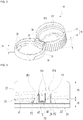
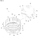
- the container cap 40 having a function of maintaining an open state may include an indication ring 44, which can be prevented from being separated by a latching jaw C formed in a spout N of a container B, a cap body 42 screw-coupled to an outer peripheral surface E/S of the spout N of the container B and having a lower portion spaced apart from an upper side of the indication ring 44 to form an cut portion 52, a hinge portion connecting the cap body 42 and the indication ring 44 to each other in a partial section of a circumference of the cut portion 52 disposed between the cap body 42 and the indication ring 44, and a bridge 20 that supports an interval between the cap body 42 and the indication ring 44 along the circumference of the cut portion 52 and cut as the interval of the cut portion 52 is enlarged when the cap body 42 is opened.
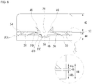
- the hinge portion 56 has widthwise opposite edge parts adjacent to ends of opposite cut portions 52 and depressed from the outside to the inside thereof, and a bending guide groove 48 formed to be integrally connected to the cap body 42, the indication ring 44, and the hinge portion 56.
- the bending guide groove 48 has a depth from an outer side to an inner side thereof, and forms an inclined surface having a thickness gradually reduced from a widthwise center of the hinge portion 56 (circumferential direction of the cap body 42) to an outer edge thereof, so that a portion of the bending guide portion 48 is thin at the sidewall of the cap body 42 formed at an upper side adjacent to the cut portion 52.
- the thinly formed portion of the bending guide groove 48 may form a cutout line O/L such that the cutting can be gradually performed from the thin portion under the tension applied to the indication ring 44a located at an upper side of the slit 46 in a section between both ends of the slit 46 when the cut portion 52 is enlarged in the process of opening of the cap body 42.
- a portion where the thickness of the bending guide groove 48 gradually increases in the widthwise center direction of the hinge portion 56 may not be gradually cut in response to the tension acting on the indication ring 44a in the above-described section. That is, the portion is provided to endure the tension acting on the indication ring 44a without incision.
- the hinge portion 56 described above has a protrusion portion 50 that protrudes downward at the lower portion of the widthwise center of the hinge portion 56, that is, the lower portion of the indication ring 44a on the upper side of the slit 46 which is integrally connected.
- a concave portion 49 having a depth defined downward is formed at an upper portion of the indication ring 44b provided at a lower portion of the slit 46 corresponding to the protrusion portion 50 such that the concave portion 49 has a shape corresponding to a shape of the protrusion portion 50 at a predetermined interval.
- the above-described slit 46 may be formed along an intermediate portion of the vertical direction of the indication ring 44 and extend to be connected to the concave portion 49 having a depth defined downward at a position corresponding to the protrusion portion 50.
- At least one twist groove 54 having a width, a length and a depth defined from an outside to an inside thereof may be formed in the above-described section, that is, the section of the indication ring 44a provided on the upper side of the slit 46, which extends from both ends of the slit 46 to both ends of the cut portion 52.
- the twist groove 54 has a shape in which a longitudinal direction is inclined with respect to a vertical direction at a predetermined angle, and specifically, one upper end of the twist groove 54 in the longitudinal direction is adjacent to the hinge portion 56 and one lower end of the twist groove 54 is adjacent to an end of the slit 46.
- the force of restoring the original shape is provided while the indication ring 44 on the upper side of the slit 46 is twisted.
- the restoring force may provide a rotational force to the cap body 42 to cover the opening of the spout N of the container B, and the above-described twist groove 54 induces deformation of the twisted state to relieve the restoring force due to the twist.
- the twist groove 54 is provided to allow the above section to be easily twisted while allowing the tension to be applied only onto the section of the indication ring 44 provided at the upper side of the slit 46 extending from both ends of the slit 46 to both ends of the cut portion 52 in a state in which the cap body 42 is opened.
Landscapes
- Engineering & Computer Science (AREA)
- Mechanical Engineering (AREA)
- Closures For Containers (AREA)
Applications Claiming Priority (2)
| Application Number | Priority Date | Filing Date | Title |
|---|---|---|---|
| KR1020170100511A KR102195928B1 (ko) | 2017-03-07 | 2017-08-08 | 개방상태 유지기능을 갖는 용기마개 |
| PCT/KR2018/008874 WO2019031779A1 (ko) | 2017-03-07 | 2018-08-06 | 개방상태 유지기능을 갖는 용기마개 |
Publications (4)
| Publication Number | Publication Date |
|---|---|
| EP3689774A1 true EP3689774A1 (de) | 2020-08-05 |
| EP3689774A4 EP3689774A4 (de) | 2021-07-07 |
| EP3689774C0 EP3689774C0 (de) | 2025-12-03 |
| EP3689774B1 EP3689774B1 (de) | 2025-12-03 |
Family
ID=71141414
Family Applications (1)
| Application Number | Title | Priority Date | Filing Date |
|---|---|---|---|
| EP18842944.3A Active EP3689774B1 (de) | 2017-08-08 | 2018-08-06 | Behälterdeckel mit funktion zur aufrechterhaltung des offenen zustandes |
Country Status (4)
| Country | Link |
|---|---|
| EP (1) | EP3689774B1 (de) |
| JP (1) | JP7314470B2 (de) |
| ES (1) | ES3055331T3 (de) |
| PH (1) | PH12020500293A1 (de) |
Cited By (6)
| Publication number | Priority date | Publication date | Assignee | Title |
|---|---|---|---|---|
| WO2020077162A1 (en) | 2018-10-12 | 2020-04-16 | Closure System International Inc. | Twist and flip lock closure |
| EP3976488A1 (de) * | 2019-07-22 | 2022-04-06 | Sacmi Cooperativa Meccanici Imola Societa' Cooperativa | Kappe zum verschliessen eines behälters, kombination aus einer kappe und einem hals |
| CN115771671A (zh) * | 2022-12-05 | 2023-03-10 | 广州雅塑包装技术服务有限公司 | 一种连体盖、连体盖切环设备及其工艺 |
| EP4277858A1 (de) * | 2021-01-12 | 2023-11-22 | Sacmi Cooperativa Meccanici Imola Societa' Cooperativa | Kappe für behälter |
| EP4442600A1 (de) | 2023-04-06 | 2024-10-09 | SIG Services AG | Wiederverschliessbare kappe zur montage auf einem behälterausguss |
| EP4650296A1 (de) | 2024-05-16 | 2025-11-19 | UAB "Plastikse" | Kunststoffgebundene kappe für einen behälter und herstellungsverfahren |
Family Cites Families (13)
| Publication number | Priority date | Publication date | Assignee | Title |
|---|---|---|---|---|
| JPS62109760A (ja) * | 1985-07-31 | 1987-05-20 | エイシ−アイ・オ−ストラリア・リミテツド | 容器の閉鎖装置 |
| FR2785264B1 (fr) * | 1998-10-29 | 2001-01-05 | Crown Cork & Seal Tech Corp | Dispositif de bouchage |
| JP4441723B2 (ja) * | 2003-07-16 | 2010-03-31 | 東京ライト工業株式会社 | 蓋付きキャップのヒンジ構造 |
| WO2006026836A1 (en) * | 2004-09-07 | 2006-03-16 | Marcel Van Ryn | Tamper indicative closure |
| WO2006099214A2 (en) * | 2005-03-11 | 2006-09-21 | Berry Plastics Corporation | Tamper-evident closure |
| JP4846466B2 (ja) * | 2006-06-26 | 2011-12-28 | 株式会社Csiジャパン | キャップおよび閉止装置ならびに飲料入り閉止装置 |
| US20110297682A1 (en) * | 2007-06-22 | 2011-12-08 | Si Joong Kwon | Container with anti-loss and anti-idle-rotation cap |
| RU2478542C2 (ru) * | 2008-07-08 | 2013-04-10 | Джапан Краун Корк Ко., Лтд. | Выполненная из синтетической смолы крышка контейнера |
| KR100981240B1 (ko) * | 2010-03-23 | 2010-09-10 | 권시중 | 공회전 방지 버팀대가 구비된 포장용기 마개 |
| CN102652098B (zh) * | 2010-01-25 | 2014-10-29 | 权始重 | 防止瓶盖丢失或空转的容器 |
| JP2013518002A (ja) * | 2010-01-28 | 2013-05-20 | グリーンキャップ カンパニー リミテッド | 包装容器栓 |
| JP6047372B2 (ja) * | 2012-10-31 | 2016-12-21 | 株式会社吉野工業所 | キャップ |
| KR101325850B1 (ko) * | 2013-06-09 | 2013-11-05 | 권시중 | 포장용기 마개 |
-
2018
- 2018-08-06 EP EP18842944.3A patent/EP3689774B1/de active Active
- 2018-08-06 JP JP2020506886A patent/JP7314470B2/ja active Active
- 2018-08-06 ES ES18842944T patent/ES3055331T3/es active Active
-
2020
- 2020-02-10 PH PH12020500293A patent/PH12020500293A1/en unknown
Cited By (10)
| Publication number | Priority date | Publication date | Assignee | Title |
|---|---|---|---|---|
| WO2020077162A1 (en) | 2018-10-12 | 2020-04-16 | Closure System International Inc. | Twist and flip lock closure |
| EP3976488A1 (de) * | 2019-07-22 | 2022-04-06 | Sacmi Cooperativa Meccanici Imola Societa' Cooperativa | Kappe zum verschliessen eines behälters, kombination aus einer kappe und einem hals |
| EP3976488B1 (de) * | 2019-07-22 | 2025-12-03 | Sacmi Cooperativa Meccanici Imola Societa' Cooperativa | Kappe zum verschliessen eines behälters, kombination aus einer kappe und einem hals |
| EP4277858A1 (de) * | 2021-01-12 | 2023-11-22 | Sacmi Cooperativa Meccanici Imola Societa' Cooperativa | Kappe für behälter |
| EP4277858B1 (de) * | 2021-01-12 | 2026-02-25 | Sacmi Cooperativa Meccanici Imola Societa' Cooperativa | Kappe für behälter |
| CN115771671A (zh) * | 2022-12-05 | 2023-03-10 | 广州雅塑包装技术服务有限公司 | 一种连体盖、连体盖切环设备及其工艺 |
| CN115771671B (zh) * | 2022-12-05 | 2023-07-04 | 广州雅塑包装技术服务有限公司 | 一种连体盖切环设备及其工艺 |
| EP4442600A1 (de) | 2023-04-06 | 2024-10-09 | SIG Services AG | Wiederverschliessbare kappe zur montage auf einem behälterausguss |
| WO2024208454A1 (en) | 2023-04-06 | 2024-10-10 | Sig Services Ag | Reclosable cap to be mounted on a spout of a container |
| EP4650296A1 (de) | 2024-05-16 | 2025-11-19 | UAB "Plastikse" | Kunststoffgebundene kappe für einen behälter und herstellungsverfahren |
Also Published As
| Publication number | Publication date |
|---|---|
| EP3689774C0 (de) | 2025-12-03 |
| ES3055331T3 (en) | 2026-02-11 |
| EP3689774B1 (de) | 2025-12-03 |
| EP3689774A4 (de) | 2021-07-07 |
| JP2020529950A (ja) | 2020-10-15 |
| PH12020500293A1 (en) | 2021-01-11 |
| JP7314470B2 (ja) | 2023-07-26 |
Similar Documents
| Publication | Publication Date | Title |
|---|---|---|
| US20200207525A1 (en) | Container cap having function of maintaining open state | |
| EP3689774A1 (de) | Behälterdeckel mit funktion zur aufrechterhaltung des offenen zustandes | |
| AU2019204130B2 (en) | Disinfecting wipes dispenser | |
| KR100981240B1 (ko) | 공회전 방지 버팀대가 구비된 포장용기 마개 | |
| EP2782842B1 (de) | Verschluss mit einem manipulationssicherungsstreifen | |
| RU2531898C2 (ru) | Контейнер | |
| US11358759B2 (en) | Container with lid opener | |
| US20180317720A1 (en) | Disinfecting wipes dispenser | |
| JP7039069B1 (ja) | プルリング及びボトルキャップ | |
| JP6575960B2 (ja) | 抜栓キャップ | |
| KR200493583Y1 (ko) | 원터치 캡 일체형 화장품 용기 | |
| JP6639921B2 (ja) | キャップ | |
| KR101195007B1 (ko) | 이탈방지용 병마개 | |
| JP4461317B2 (ja) | 容器から分離容易なキャップ体 | |
| JP6812074B2 (ja) | 封印付きヒンジキャップ | |
| KR100884823B1 (ko) | 위조방지용 마개 | |
| KR20220113792A (ko) | 용기의 나사산 구조 | |
| JP5399042B2 (ja) | 抜栓式キャップ | |
| JP4793813B2 (ja) | 中栓付き容器 | |
| EP4219330A1 (de) | Nichtablösbare kappe | |
| JP5709515B2 (ja) | 抜栓式キャップ | |
| KR20260006369A (ko) | 뚜껑 오픈 시 자동 제거되는 수축 레이블 | |
| KR101941473B1 (ko) | 캔 오프너 | |
| JP4002330B2 (ja) | 分別機能に優れたプラスチックキャップ | |
| JP4578286B2 (ja) | ヒンジ蓋付き容器 |
Legal Events
| Date | Code | Title | Description |
|---|---|---|---|
| STAA | Information on the status of an ep patent application or granted ep patent |
Free format text: STATUS: THE INTERNATIONAL PUBLICATION HAS BEEN MADE |
|
| PUAI | Public reference made under article 153(3) epc to a published international application that has entered the european phase |
Free format text: ORIGINAL CODE: 0009012 |
|
| STAA | Information on the status of an ep patent application or granted ep patent |
Free format text: STATUS: REQUEST FOR EXAMINATION WAS MADE |
|
| 17P | Request for examination filed |
Effective date: 20200529 |
|
| AK | Designated contracting states |
Kind code of ref document: A1 Designated state(s): AL AT BE BG CH CY CZ DE DK EE ES FI FR GB GR HR HU IE IS IT LI LT LU LV MC MK MT NL NO PL PT RO RS SE SI SK SM TR |
|
| AX | Request for extension of the european patent |
Extension state: BA ME |
|
| DAV | Request for validation of the european patent (deleted) | ||
| DAX | Request for extension of the european patent (deleted) | ||
| A4 | Supplementary search report drawn up and despatched |
Effective date: 20210604 |
|
| RIC1 | Information provided on ipc code assigned before grant |
Ipc: B65D 41/04 20060101AFI20210528BHEP Ipc: B65D 43/24 20060101ALI20210528BHEP Ipc: B65D 47/08 20060101ALI20210528BHEP Ipc: B65D 55/16 20060101ALI20210528BHEP Ipc: B65D 41/34 20060101ALI20210528BHEP Ipc: B65D 55/02 20060101ALI20210528BHEP |
|
| STAA | Information on the status of an ep patent application or granted ep patent |
Free format text: STATUS: EXAMINATION IS IN PROGRESS |
|
| 17Q | First examination report despatched |
Effective date: 20230306 |
|
| STAA | Information on the status of an ep patent application or granted ep patent |
Free format text: STATUS: THE APPLICATION IS DEEMED TO BE WITHDRAWN |
|
| 18D | Application deemed to be withdrawn |
Effective date: 20230718 |
|
| 18RA | Request filed for re-establishment of rights before grant |
Effective date: 20240315 |
|
| STAA | Information on the status of an ep patent application or granted ep patent |
Free format text: STATUS: EXAMINATION IS IN PROGRESS |
|
| D18D | Application deemed to be withdrawn (deleted) | ||
| GRAP | Despatch of communication of intention to grant a patent |
Free format text: ORIGINAL CODE: EPIDOSNIGR1 |
|
| STAA | Information on the status of an ep patent application or granted ep patent |
Free format text: STATUS: GRANT OF PATENT IS INTENDED |
|
| INTG | Intention to grant announced |
Effective date: 20250424 |
|
| GRAS | Grant fee paid |
Free format text: ORIGINAL CODE: EPIDOSNIGR3 |
|
| GRAA | (expected) grant |
Free format text: ORIGINAL CODE: 0009210 |
|
| STAA | Information on the status of an ep patent application or granted ep patent |
Free format text: STATUS: THE PATENT HAS BEEN GRANTED |
|
| AK | Designated contracting states |
Kind code of ref document: B1 Designated state(s): AL AT BE BG CH CY CZ DE DK EE ES FI FR GB GR HR HU IE IS IT LI LT LU LV MC MK MT NL NO PL PT RO RS SE SI SK SM TR |
|
| REG | Reference to a national code |
Ref country code: CH Ref legal event code: F10 Free format text: ST27 STATUS EVENT CODE: U-0-0-F10-F00 (AS PROVIDED BY THE NATIONAL OFFICE) Effective date: 20251203 |
|
| REG | Reference to a national code |
Ref country code: DE Ref legal event code: R096 Ref document number: 602018087684 Country of ref document: DE |
|
| REG | Reference to a national code |
Ref country code: IE Ref legal event code: FG4D |
|
| REG | Reference to a national code |
Ref country code: ES Ref legal event code: FG2A Ref document number: 3055331 Country of ref document: ES Kind code of ref document: T3 Effective date: 20260211 |
|
| U01 | Request for unitary effect filed |
Effective date: 20251222 |
|
| U07 | Unitary effect registered |
Designated state(s): AT BE BG DE DK EE FI FR IT LT LU LV MT NL PT RO SE SI Effective date: 20260109 |
|
| PG25 | Lapsed in a contracting state [announced via postgrant information from national office to epo] |
Ref country code: NO Free format text: LAPSE BECAUSE OF FAILURE TO SUBMIT A TRANSLATION OF THE DESCRIPTION OR TO PAY THE FEE WITHIN THE PRESCRIBED TIME-LIMIT Effective date: 20260303 |
|
| PG25 | Lapsed in a contracting state [announced via postgrant information from national office to epo] |
Ref country code: HR Free format text: LAPSE BECAUSE OF FAILURE TO SUBMIT A TRANSLATION OF THE DESCRIPTION OR TO PAY THE FEE WITHIN THE PRESCRIBED TIME-LIMIT Effective date: 20251203 |
|
| PG25 | Lapsed in a contracting state [announced via postgrant information from national office to epo] |
Ref country code: RS Free format text: LAPSE BECAUSE OF FAILURE TO SUBMIT A TRANSLATION OF THE DESCRIPTION OR TO PAY THE FEE WITHIN THE PRESCRIBED TIME-LIMIT Effective date: 20260303 |
|
| PG25 | Lapsed in a contracting state [announced via postgrant information from national office to epo] |
Ref country code: PL Free format text: LAPSE BECAUSE OF FAILURE TO SUBMIT A TRANSLATION OF THE DESCRIPTION OR TO PAY THE FEE WITHIN THE PRESCRIBED TIME-LIMIT Effective date: 20251203 |