EP3690111B1 - Wäschebehandlungsvorrichtung und verfahren zur steuerung davon - Google Patents
Wäschebehandlungsvorrichtung und verfahren zur steuerung davon Download PDFInfo
- Publication number
- EP3690111B1 EP3690111B1 EP20154875.7A EP20154875A EP3690111B1 EP 3690111 B1 EP3690111 B1 EP 3690111B1 EP 20154875 A EP20154875 A EP 20154875A EP 3690111 B1 EP3690111 B1 EP 3690111B1
- Authority
- EP
- European Patent Office
- Prior art keywords
- drum
- location
- tub
- treating apparatus
- cabinet
- Prior art date
- Legal status (The legal status is an assumption and is not a legal conclusion. Google has not performed a legal analysis and makes no representation as to the accuracy of the status listed.)
- Active
Links
Images




Classifications
-
- D—TEXTILES; PAPER
- D06—TREATMENT OF TEXTILES OR THE LIKE; LAUNDERING; FLEXIBLE MATERIALS NOT OTHERWISE PROVIDED FOR
- D06F—LAUNDERING, DRYING, IRONING, PRESSING OR FOLDING TEXTILE ARTICLES
- D06F37/00—Details specific to washing machines covered by groups D06F21/00 - D06F25/00
- D06F37/20—Mountings, e.g. resilient mountings, for the rotary receptacle, motor, tub or casing; Preventing or damping vibrations
- D06F37/22—Mountings, e.g. resilient mountings, for the rotary receptacle, motor, tub or casing; Preventing or damping vibrations in machines with a receptacle rotating or oscillating about a horizontal axis
-
- D—TEXTILES; PAPER
- D06—TREATMENT OF TEXTILES OR THE LIKE; LAUNDERING; FLEXIBLE MATERIALS NOT OTHERWISE PROVIDED FOR
- D06F—LAUNDERING, DRYING, IRONING, PRESSING OR FOLDING TEXTILE ARTICLES
- D06F37/00—Details specific to washing machines covered by groups D06F21/00 - D06F25/00
- D06F37/26—Casings; Tubs
- D06F37/265—Counterweights mounted to the tub; Mountings therefor
Definitions
- the present disclosure relates to a laundry treating apparatus and a method for controlling the same.
- a laundry treating apparatus includes an apparatus for washing laundry, an apparatus for drying laundry, and an apparatus for washing or drying laundry according to a user's selection.
- a conventional laundry treating apparatus is classified into a front loading type apparatus for loading laundry into the apparatus through a laundry inlet defined in a front face of the apparatus, and a top loading type apparatus for loading laundry into the apparatus through a laundry inlet defined in a top face of the apparatus.
- the front loading type laundry treating apparatus includes a cabinet having a laundry inlet defined in a front face thereof, a tub disposed inside the cabinet to store water therein, a drum rotatably disposed inside the tub to store laundry therein, a spring that connects an upper portion of a circumferential face of the tub to the cabinet, and a damper that connects a lower portion of a circumferential face of the tub to a bottom face of the cabinet.
- the damper disposed in the conventional laundry treating apparatus may include a plurality of dampers. Not only the numbers of dampers disposed in the left and right sides to a vertical line passing through a center of the tub are the same, but also the dampers disposed in the left and right sides are disposed at positions symmetrical with respect to the vertical line.
- the laundry treating apparatus having the above-described structure has an advantage of effectively absorbing vibration generated from the tub even when the drum rotates in any one of clockwise and counterclockwise directions.
- the vibration of the tub is the largest when the drum is rotated only in one of clockwise and counterclockwise directions at a high rotational speed.
- the conventional laundry treating apparatus having the above-described structure may have the number of dampers larger than necessary.
- GB 2 148 953 A relates to a support system including a washing machine drum resting on at least two telescopic shock absorbers in a washing machine frame. There may be two pairs of shock absorbers. In other arrangements, there may be from two to five of the shock absorbers, the conventional suspension springs may be omitted or retained, and the conventional ballast or counterweights may be omitted or retained. At least two of the shock absorbers, form angles of approximately 15° with respect to the vertical. One or two shock absorbers may be linked to the motor casing and be at approximately 60° to the vertical.
- WO 2004/072350 A2 relates to a drum type washing machine for smooth attenuation of different directions of vibration transmissive to a tub during rotation of the drum.
- the drum type washing machine includes a cabinet having an opening in a front surface, a tub inside of the cabinet having a drum rotatably mounted on an inside thereof, first, and second dampers connected between one side of a circumferential surface of the tub and the cabinet respectively, a third damper connected between the other side of the circumferential surface of the tub and the cabinet, and at least one spring connected between the circumferential surface of the tub and the cabinet.
- the at least one spring includes a first spring connected to an upper surface of the tub on a side the same with the first and second dampers for attenuating up/down and left/right vibrations of the tub, and second and third springs connected to the upper surface of the tub on a side the same with the third damper for attenuating up/down, left/right and front/rear vibrations of the tub.
- JP 2017 056076 A relates to a drum type washing machine comprising a damper which is provided in order to reduce vibration and noise.
- a damper for supporting a lower part of a water tub unit from a base bottom part of a washing machine housing a first damper is disposed more on a front right side and a second damper is disposed more on a back right side from the center of gravity in the rotational axis direction of the water tub unit, and a third vibration-proof damper is disposed on a left side.
- damping forces in the vertical direction of the three dampers are set respectively, and the second damper is disposed in the substantially horizontal direction in order to unify the vertical amplitude of the water tub unit during dewatering.
- An object of the present disclosure is basically to solve the problem of the conventional laundry treating apparatus as mentioned above.
- a further object of the present disclosure is to provide a laundry treating apparatus for effectively damping the vibration of the tub using a minimum number of dampers, and to provide a method for controlling the same.
- the present disclosure provides a laundry treating apparatus capable of effectively attenuating the vibration of the drum and tub by fixing the tub to the cabinet via dampers disposed in asymmetrical positions and disposed in asymmetric numbers with respect to a central vertical line, and provides a method for controlling the same.
- the present disclosure provides a laundry treating apparatus capable of maximizing attenuation of the vibration by a tub support using weight balancers having different weights or fixed to asymmetric positions of the tub, and provides a method for controlling the same.
- One aspect of the present disclosure provides a laundry treating apparatus comprising: a cabinet; a tub having a hollow cylindrical shape; a drum rotatably disposed inside the tub to store laundry therein; an elastic member to connect an upper region of a circumferential face of the tub to the cabinet; and dampers for connecting a lower region of the circumferential face of the tub to the cabinet, wherein the number of dampers on one side to a vertical line passing through a rotation center of the drum is greater than the number of dampers on the other side to the vertical line.
- a laundry treating apparatus comprising: a cabinet; a tub having a hollow cylindrical shape; a drum rotatably disposed inside the tub to store laundry therein; an elastic member to connect an upper region of a circumferential face of the tub to the cabinet; dampers for connecting a lower region of the circumferential face of the tub to the cabinet, wherein the number of dampers on one side to a vertical line passing through a rotation center of the drum is greater than the number of dampers on the other side to the vertical line; and a controller, wherein a RPM (revolutions per minute) set for the drum is greater than a preset reference RPM, the controller is configured for rotating the drum in a direction from a location in which the smaller number of dampers are disposed to a location in which the larger number of dampers are disposed.
- RPM repetitions per minute
- a laundry treating apparatus comprising: a cabinet having a cabinet laundry inlet defined therein; a tub including: a tub body having a hollow cylindrical shape; a front cover facing the cabinet laundry inlet to define a front face of the tub body; a rear cover defining a rear face of the tub body; and a tub laundry inlet passing through the front cover and communicating with the cabinet laundry inlet; a drum rotatably disposed inside the tub to store laundry therein; a drum driver for rotating the drum; an elastic member to connect, to the cabinet, a portion of a space defined in the tub body, the portion being located above a horizontal line passing through a rotation center of the drum; first and second dampers to connect, to the cabinet, a portion of the space defined in the tub body, the portion being located below the horizontal line, wherein a first location is defined as one of left and right portions of the space defined in the tub body relative to a vertical line passing through the rotation center of the drum, while a second location is defined as the other of the left
- the laundry treating apparatus further comprises a controller, wherein when a RPM (revolutions per minute) set for the drum is greater than a preset reference RPM, the controller is configured for controlling the drum driver so that the drum rotates in a direction from the second location toward the first location.
- a RPM repetitions per minute
- the reference RPM is set to be equal to or higher than an RPM causing a resonance of the tub.
- the laundry treating apparatus further comprises: a first weight balancer disposed on one portion positionally corresponding to the first location among two portions of the front cover divided by a vertical line V passing through the rotation center of the drum; and a second weight balancer disposed on the other portion positionally corresponding to the second location among the two portions of the front cover divided by the vertical line passing through the rotation center of the drum, wherein a weight of the first weight balancer is set to be larger than a weight of the second weight balancer.
- the laundry treating apparatus further comprises a third weight balancer disposed fixedly in a portion of a space defined by the rear cover of the tub, the portion being located below or above the horizontal line passing through the rotation center of the drum, wherein a shape of the third weight balancer is asymmetric with respect to the vertical line passing through the rotation center of the drum.
- a weight of a portion of the third weight balancer extending from the vertical line toward the first location is set to be larger than a weight of a portion thereof extending from the vertical line toward the second location.
- the laundry treating apparatus further comprises a fourth weight balancer disposed fixedly in a portion of a space defined by the rear cover of the tub, the portion being located above the horizontal line passing through the rotation center of the drum, wherein a shape of the fourth weight balancer is asymmetric with respect to the vertical line passing through the rotation center of the drum.
- a weight of a portion of the fourth weight balancer extending from the vertical line toward the first location is set to be larger than a weight of a portion thereof extending from the vertical line toward the second location.
- the laundry treating apparatus further comprises: an insulator for connecting the cabinet laundry inlet and the tub laundry inlet with each other, wherein the insulator is embodied as an elastic body; and a residual-water discharge pipe for connecting the front cover to a portion of a space defined by the insulator, the portion being located below the horizontal line passing through the rotation center of the drum, wherein the residual-water discharge pipe is constructed to guide water inside the insulator to the tub body.
- the first weight balancer includes: a first body fixed to the front cover and located inside a space defined by the front cover; and a first protruding body protruding from the first body and located outside the space defined by the front cover
- the second weight balancer includes: a second body fixed to the front cover and located inside a space defined by the front cover; a second protruding body protruding from the second body and located outside the space defined by the front cover; and a receiving groove concavely defined in one end of the second body to receive the residual-water discharge pipe therein to prevent the residual-water discharge pipe from interfering with the second body.
- One aspect of the present disclosure provides a method for controlling a laundry treating apparatus, wherein the apparatus includes: a cabinet having a cabinet laundry inlet defined therein; a tub having a hollow cylindrical shape; a drum rotatably disposed inside the tub to store laundry therein; a drum driver for rotating the drum; an elastic member to connect, to the cabinet, a portion of a space defined in the tub, the portion being located above a horizontal line passing through a rotation center of the drum; first and second dampers to connect, to the cabinet, a portion of the space defined in the tub, the portion being located below the horizontal line, wherein a first location is defined as one of left and right portions of the space defined in the tub relative to a vertical line passing through the rotation center of the drum, while a second location is defined as the other of the left and right portions, wherein both of the first damper and second damper are disposed at the first location; and a third damper to connect, to the cabinet, a portion of the space defined in the tub, the portion being located below the horizontal line
- the method further comprises, when the RPM set for the drum is lower than the preset reference RPM, controlling the drum driver so that the drum rotates in a direction from the first location toward the second location.
- the method further comprises, when the RPM set for the drum is lower than the preset reference RPM, controlling the drum driver so that a step of rotating the drum in a direction from the first location to the second location, and a step of rotating the drum in a direction from the second location to the first location are alternately performed.
- a laundry treating apparatus for effectively damping the vibration of the tub using a minimum number of dampers, and a method for controlling the same may be realized.
- a laundry treating apparatus capable of effectively attenuating the vibration of the drum and tub by fixing the tub to the cabinet via dampers disposed in asymmetrical positions and disposed in asymmetric numbers with respect to a central vertical line, and a method for controlling the same may be realized.
- a laundry treating apparatus capable of maximizing attenuation of the vibration by a tub support using weight balancers having different weights or fixed to asymmetric positions of the tub, and a method for controlling the same may be realized.
- first element or layer when a first element or layer is referred to as being present "on” or “beneath” a second element or layer, the first element may be disposed directly on or beneath the second element or may be disposed indirectly on or beneath the second element with a third element or layer being disposed between the first and second elements or layers.
- first element when an element or layer is referred to as being “connected to”, or “coupled to” another element or layer, it may be directly on, connected to, or coupled to the other element or layer, or one or more intervening elements or layers may be present.
- an element or layer when an element or layer is referred to as being “between” two elements or layers, it may be the only element or layer between the two elements or layers, or one or more intervening elements or layers may be present.
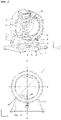
- a laundry treating apparatus 100 includes a cabinet 1, a tub 2 disposed inside the cabinet to store water therein, and a drum 3 rotatably disposed inside the tub for storing laundry therein.
- the cabinet 1 has a base 15 to form a bottom face of the laundry treating apparatus (a bottom face of the cabinet), a front panel to form a front face of the laundry treating apparatus, a rear panel to form a rear face of the laundry treating apparatus, and a top face of the laundry treating apparatus, and a first side panel 16 (see FIG. 2 ) and a second side panel 17 (see FIG. 2 ) fixed to the base 15 to form left and right side faces of the laundry treating apparatus, respectively.
- the front panel has a cabinet laundry inlet 11 defined therein through which laundry is input into the drum 3 or laundry is withdrawn from the drum to an outside of the cabinet.
- the cabinet laundry inlet 11 may be opened and closed by a door 13.
- the door 13 may be rotatably coupled to the front panel.
- the tub 2 has a hollow cylindrical tub body 21, a front cover 211 fixed to the tub body to form a front face of the tub, and a rear cover 213 fixed to the tub body to form a rear face of the tub.
- the front cover 211 faces the front panel having the cabinet laundry inlet 11.
- the rear cover 213 faces the rear panel.
- the front cover 211 has a tub laundry inlet 23 defined therein communicating with the cabinet laundry inlet 11.
- the cabinet laundry inlet 11 and the tub laundry inlet 23 are connected with each other via an insulator.
- the insulator not only prevents water stored in the tub body 21 from being discharged to the cabinet 1 through the tub laundry inlet 23, but also attenuates the vibration of the tub body 21 from being transmitted to the cabinet 1.
- the insulator is embodied as an elastic body (made of rubber or the like) and has an insulating body 41 connecting the cabinet laundry inlet 11 and the tub laundry inlet 23 with each other.
- the insulating body 41 has a cylindrical first fixed body having one end fixed to the cabinet laundry inlet 11, a cylindrical second fixed body having the other end fixed to the tub laundry inlet 23, a connecting body connecting a free end of the first fixed body and a free end of the second fixed body with each other.
- the insulator may further have a residual-water discharge pipe 49 connecting the insulating body 41 and the front cover 211 of the tub body with each other.
- the residual-water discharge pipe 49 is preferably configured to connect a portion of a space defined by the insulating body 41 as located below a horizontal line H passing through a rotation center of the drum 3 to the front cover 211. This configuration is intended to move the water inside the insulating body 41 to the tub body 21 without a separate device.
- the drum 3 includes a drum body 31 rotatable inside the tub body 21.
- the drum body 31 has a hollow cylindrical shape.
- Each of a circumferential face, a front face and a rear face of the drum body 31 has drum through-holes 32 defined therein which communicate an inside of the drum body with an inside of the tub body.
- a drum laundry inlet 33 is defined in a face (the front face of the drum) of a space defined by the drum body 31 facing the cabinet laundry inlet 11.
- the drum body 31 is rotated by a drum driver 35.
- the drum driver 35 includes a stator 351 fixed to a back of the tub body 21 to generate a rotating field, a rotor 353 located outside of the tub body 21 to rotate using the magnetic field, and a rotation shaft 355 to penetrate the rear face of the tub body 21 and connect the rotor 353 and the drum body 31 with each other.
- the water stored in the tub body 21 is discharged out of the cabinet 1 via a water discharger 6.
- the water discharger 6 may include a chamber 61 which provides a space for storing water therein, a first water discharge pipe 63 which directs water from the tub body 21 to the chamber 61, and a water discharge pump 65 to transfer water introduced into the chamber 61 to a second water discharge pipe 67.
- the second water discharge pipe 67 refers to means for directing the water discharged from the water discharge pump 65 to an outside of the cabinet and may be configured such that the highest point of the second water discharge pipe 67 passes through a point higher than the lowest point of the tub laundry inlet 23.
- the laundry treating apparatus 100 may further include a water ejector 7 for ejecting water stored in the tub body 21 toward the drum laundry inlet 33.
- the water ejector 7 may include a channel body 71 fixed to the front panel of the tub body 21, a supply pipe 72 that guides water to the channel body 71, and a circulating pump 73 that moves the water inside the tub body 21 to the supply pipe 72.
- the channel body 71 has a fan-shaped channel defined therein extending along a circumferential face of the tub laundry inlet 23.
- the circulating pump 73 may be configured to supply water inside the chamber 61 to the supply pipe 72.
- the channel body 71 may has a first nozzle 711, a second nozzle 713, a third nozzle 715, and a fourth nozzle 717 from which water is discharged.
- the first nozzle 711 and second nozzle 713 may be disposed on a left side to a vertical line V passing through a center of the tub laundry inlet 23.
- the third nozzle 715 and fourth nozzle 717 may be disposed on a right side to the vertical line V.
- a detergent supply 5 included in the laundry treating apparatus 100 may be configured to include a casing 51 disposed in the cabinet 1, and a drawer 52 withdrawable from the casing 51.
- the drawer 52 housed inside the casing 51 may be drawn out of the cabinet 1 through a drawer outlet (not shown) configured to penetrate the front panel of the cabinet 1.
- the drawer 52 may have a polyhedron shape (hexahedron shape) with an open top face.
- the drawer may be configured to include a storage 521 which provides a space in which a detergent is stored, and a detergent outlet 523 which communicates the storage 521 with the casing 51.
- the detergent outlet 523 may be embodied as a through-hole passing through a rear face or bottom face of the storage 521 or may be embodied as a bell trap disposed on a bottom face of the storage 521.
- the casing 51 has a water supply that supplies water to the storage 521.
- FIG. 1 shows an example where the water supply supplies water to a top face of the casing 51.
- the water supply includes a water supply pipe 561 that supplies water from a water supply source to the storage 521, and a water supply valve 563 that opens or closes the water supply pipe 561 according to a control signal from a controller (not shown).
- a controller not shown
- Water and detergent discharged to the casing 51 may be fed into the tub body 21 through the insulating body 41.
- the insulator 4 may have an inflow pipe 43 into which water and detergent are introduced.
- the detergent supply 5 may have an outflow pipe 53 which directs the detergent and water to the inflow pipe 42.
- Each of the inflow pipe 42 and the outflow pipe 53 may be made of an elastic material (rubber or the like). Thus, the inflow pipe 42 and outflow pipe 53 may allow minimizing the transfer of the vibration to the casing 51 and the front panel 15.
- the tub 2 having the above-described structure is fixed inside the cabinet 1 via a tub support.
- the tub support may be composed of an elastic member 91 and 92 and dampers 93, 94 and 95.
- the elastic member may include a first spring 91 and a second spring 92 that connect a portion of a circumferential face of the tub body 21 located above a horizontal line H passing through a center of the tub body to the cabinet 1.
- the cabinet 1 may further include a frame to which each spring is fixed.
- the frame may include a first frame disposed at a corner where the first side panel 16 and the top panel meet with each other, and to which the first spring 91 is fixed, and a second frame disposed at a corner where the top panel and the second side panel 17 meet with each other and to which the second spring 92 is fixed.
- the damper may include a plurality of dampers 93, 94 and 95 that connect the base 15 with a portion of the circumferential face of the tub body 21 located below the horizontal line H passing through the center of the tub body (or the rotation center of the drum).
- the damper may include a first damper 93 and a second damper 94 disposed at a first location, and a third damper 95 disposed at a second location.
- the first location may be defined as one of left and right portions of a space defined in the tub body 21 relative to the vertical line V passing through the center of the tub body 21.
- the second location may be defined as the other of the left and right portions of the space defined in the tub body 21 relative to the vertical line V passing through the center of the tub body 21.
- FIG. 3 shows one example where the first location is the left space relative to the vertical line V, while the second location is the right space relative to the vertical line V.
- Each of the first damper 93, second damper 94, and third damper 95 may have any structure as long as each damper may absorb the vibration of the tub body 21.
- An example thereof may be a hydraulic damper.
- the hydraulic damper may include a cylinder to provide a space for fluid to be stored therein, the cylinder being fixed to either a circumferential face of the tub body or the base 15, and a piston having one end located inside the cylinder and the other end fixed to the base 15.
- a cylinder to provide a space for fluid to be stored therein
- the cylinder being fixed to either a circumferential face of the tub body or the base 15, and a piston having one end located inside the cylinder and the other end fixed to the base 15.
- the laundry treating apparatus 100 has a feature that the number of the dampers 93 and 94 disposed at the first location and the number of the damper 95 disposed at the second location may not be equal to each other, and positions of the dampers at the first location and the position of the damper at the second location are not symmetrical with each other with respect to the vertical line.
- the number of the dampers disposed at the first location and the number of the dampers disposed at the second location are equal to each other, and positions of the dampers at the first location and the positions of the dampers at the second location are symmetrical with each other with respect to the vertical line.
- the laundry treating apparatus having the above-described structure has an advantage of effectively absorbing vibration generated from the tub body 21 even when the drum 3 rotates in any one of clockwise and counterclockwise directions.
- the vibration of the tub body 21 is the largest when the drum 3 is rotated only in one of clockwise and counterclockwise directions at a high rotational speed.
- the conventional laundry treating apparatus having the above-described structure may have the number of dampers larger than necessary.
- the drum 3 rotates in a clockwise direction in a spinning cycle.
- the dampers located on the left side to the vertical line V play a greater role in absorbing the vibration of the tub body 21, whereas the dampers located on the right side to the vertical line V play a relatively smaller role in absorbing the vibration of the tub body 21. Therefore, the conventional design in which the same numbers of the dampers are arranged at symmetrical points has a disadvantage in that a larger number of dampers are used than necessary.
- the laundry treating apparatus 100 has the feature that the number of the dampers 93 and 94 disposed at the first location and the number of the damper 95 disposed at the second location may not be equal to each other, and positions of the dampers at the first location and the position of the damper at the second location are not symmetrical with each other with respect to the vertical line. Further, the laundry treating apparatus 100 has a feature that when a RPM (revolutions per minute) set for the drum is greater than or equal to a preset reference RPM, a rotation direction of the drum 2 is specified accordingly.
- RPM revolutions per minute
- the controller controls the drum driver 35 so that the drum 3 rotates in a direction from the second location toward the first location, thereby effectively dampen the vibration of the tub body 21.
- the laundry treating apparatus 100 may effectively attenuate the vibration occurring in the tub body 21 while minimizing the number of the dampers.
- the reference RPM may be set to the same RPM as a RPM that causes a resonance of the tub body 21, or may be set to an RPM greater than the RPM that causes the resonance of the tub body 21.
- the reference RPM may be set to be equal to a RPM that causes a resonance of the laundry treating apparatus 100 or may be set to an RPM greater than the RPM that causes the resonance of the laundry treating apparatus 100.
- the controller may rotate the drum 3 in a direction from the first location to the second location.
- the third damper 95 disposed at the second location will be able to absorb the small vibration of the tub body 21.
- the controller may alternately perform a step B of rotating the drum 3 in a direction from the first location to the second location and a step A of rotating the drum 3 in a direction from the second location to the first location.
- the laundry treating apparatus may further include at least one of a front weight 81 and 82 disposed on the front cover 211 of the tub, and a rear weight 84 and 86 disposed on the rear cover 213 of the tub.
- the front weight 81 and 82 may include a first weight balancer 81 and a second weight balancer 82 disposed with the tub laundry inlet 23 interposed therebetween.
- the first weight balancer 81 may be disposed on one portion positionally corresponding to the first location among two portions of the front cover 211 divided by the vertical line V passing through the rotation center of the drum 3.
- the second weight balancer 82 may be disposed on the other portion positionally corresponding to the second location among two portions of the front cover 211 divided by the vertical line V passing through the rotation center of the drum 3.
- the laundry treating apparatus 100 may more effectively control the vibration of the tub body 21 when the drum 3 rotates at a RPM above the reference RPM.
- Increasing the weight of the tub 2 means that a large amount of energy is required to vibrate the tub 2.
- the vibration of the drum 3 to vibrate the tub 2 increases.
- the controller disposed in the laundry treating apparatus 100 rotates the drum 3 in a direction from the second location to the first location.
- the laundry treating apparatus 100 may more effectively attenuate the vibration generated from the tub body 21 when the drum rotates at a RPM higher than the reference RPM.
- the first weight balancer 81 has a first body 811 fixed to the front cover 211, and a first protruding body protruding from the first body 811 toward a corner where the first side panel 16 and the base 15 join together.
- the second weight balancer 82 may include a second body 821 fixed to the front cover 211 and a second protruding body 825 protruding from the second body 821 toward a corner at which the second side panel 17 and the base 15 join together.
- the first protruding body 815 and the second protruding body 825 act to respectively maximize the weights of the first weight balancer 81 and the second weight balancer 82 which are located inside the cabinet with a limited volume.
- At least one of the first body 811 and the second body 821 may further have an outflow pipe receiving groove for receiving the outflow pipe 53 of the detergent supply 5.
- FIG. 4 shows one example where the first weight balancer 81 has a first outflow pipe receiving groove 813 concavely defined in a surface of the first body 811, and the second weight balancer 82 has a second outflow pipe receiving groove 823 concavely defined in a surface of the second body 821.
- the configuration that the outflow pipe receiving grooves 813 and 823 are defined in the two weight balancers 81 and 82 respectively may prevent the front weight 81 and 82 from interfering with the outflow pipe 53 as a position of the detergent supply 5 changes.
- One of the first weight balancer 81 and the second weight balancer 82 may be configured to have a receiving groove defined therein to receive the residual-water discharge pipe 49 such that the weight balancers 81 and 82 is prevented from interfering with the residual-water discharge pipe 49.
- FIG. 4 illustrates an example in which the receiving groove 824 is defined in the second body 821 because the weight of the first weight balancer 81 should be set to be larger than the weight of the second weight balancer 82.
- the receiving groove 824 may be concavely defined in one end of the second body 821.
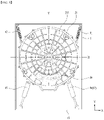
- FIG. 5 shows an example of the rear weight.
- the rear weight may include a third weight balancer 84 disposed fixedly in a portion of a space defined by the rear cover 213 of the tub as located below the horizontal line H passing through the rotation center of the drum 3.
- the third weight balancer 84 may have a symmetrical shape with respect to the vertical line V passing through the rotation center of the drum or may have an asymmetrical shape with respect to the vertical line V passing through the rotation center of the drum. In the latter case, a weight of a portion of the third weight balancer 84 extending from the vertical line V toward the first location (where the two dampers are located) is larger than a weight of a portion of the third weight balancer 84 extending from the vertical line V toward the second location (where one damper is located). This configuration is intended to more effectively dampen the vibration generated from the tub body 21 when the drum 3 rotates at a RPM higher than the reference RPM.
- the third weight balancer 84 may be fixed disposed in a portion of a space defined by the rear cover 213 as located above the horizontal line H.
- FIG. 6 shows another embodiment of the rear weight, where the rear weight includes a third weight balancer 84 fixedly disposed in a portion of the space defined by the rear cover 213 of the tub as provided below the horizontal line H, and a fourth weight balancer 86 fixedly disposed in a portion of the space defined by the rear cover 213 of the tub as provided above the horizontal line H.
- the feature of the third weight balancer 84 is the same as has been described in the embodiment of FIG. 5 . Thus, the detailed description is omitted.
- a shape of the fourth weight balancer 86 may have a shape symmetrical about the vertical line V passing through the rotation center of the drum, or an asymmetrical shape about the vertical line V passing through the rotation center of the drum. In the latter case, a weight of a portion of the fourth weight balancer 86 extending from the vertical line V toward the first location is preferably set to be larger than a weight of a portion of the fourth weight balancer 86 extending from the vertical line V toward the second location. Unlike FIG. 6 , the rear weight may include only the fourth weight balancer 86.
Landscapes
- Engineering & Computer Science (AREA)
- Textile Engineering (AREA)
- Main Body Construction Of Washing Machines And Laundry Dryers (AREA)
Claims (14)
- Wäschebehandlungsvorrichtung, aufweisend:ein Gehäuse (1) mit einem darin definierten Gehäusewäscheeinlass (11);eine Wanne (2), aufweisend:einen Wannenkörper (21) mit einer Hohlzylinderform;eine Frontabdeckung (211), die dem Gehäusewäscheeinlass (11) zugewandt ist, um eine Vorderfläche des Wannenkörpers (21) zu definieren;eine Rückabdeckung (213), die eine Rückfläche des Wannenkörpers (21) definiert; undeinen Wannenwäscheeinlass (23), der die Frontabdeckung (211) durchläuft und mit dem Gehäusewäscheeinlass (11) kommuniziert;eine Trommel (3), die drehbar im Inneren der Wanne (2) angeordnet ist, um Wäsche darin zu lagern;eine Trommelantriebseinrichtung (35) zum Drehen der Trommel (3);ein elastisches Element (91, 92), um einen Abschnitt eines in dem Wannenkörper (21) definierten Raums mit dem Gehäuse (1) zu verbinden, wobei sich der Abschnitt oberhalb einer einen Drehmittelpunkt der Trommel (3) durchlaufenden Horizontallinie (H) befindet;erste und zweite Dämpfer (93, 94), um einen Abschnitt des in dem Wannenkörper (21) definierten Raums mit dem Gehäuse (1) zu verbinden, wobei sich der Abschnitt unterhalb der Horizontallinie (H) befindet, wobei eine erste Stelle als einer von linken und rechten Abschnitten des in dem Wannenkörper (21) definierten Raums relativ zu einer den Drehmittelpunkt der Trommel (3) durchlaufenden Vertikallinie (V) definiert ist, wohingegen eine zweite Stelle als der andere der linken und rechten Abschnitte definiert ist, wobei sowohl der erste Dämpfer (93) als auch der zweite Dämpfer (94) an der ersten Stelle angeordnet sind; undeinen dritten Dämpfer (95), um einen Abschnitt des in dem Wannenkörper (21) definierten Raums mit dem Gehäuse (1) zu verbinden, wobei sich der Abschnitt unterhalb der Horizontallinie (H) befindet, wobei der dritte Dämpfer (95) an der zweiten Stelle angeordnet ist,dadurch gekennzeichnet, dassdie Wäschebehandlungsvorrichtung ferner einen Controller aufweist, wobei dann, wenn eine für die Trommel (3) festgelegte Drehzahl, UpM, größer ist als eine vorab festgelegte Referenz-UpM, der Controller konfiguriert ist, die Trommelantriebseinrichtung (35) derart zu steuern, dass sich die Trommel (3) im Uhrzeigersinn (A) von der zweiten Stelle in Richtung der ersten Stelle dreht, wenn sich die erste Stelle auf der linken Seite der Vertikallinie (V) befindet, oder sich die Trommel (3) entgegen dem Uhrzeigersinn (B) von der ersten Stelle in Richtung der zweiten Stelle dreht, wenn sich die zweite Stelle auf der linken Seite der Vertikallinie (V) befindet.
- Wäschebehandlungsvorrichtung nach Anspruch 1, wobei die Referenz-UpM dahingehend festgelegt ist, gleich oder größer einer UpM zu sein, die eine Resonanz der Wanne (2) hervorruft.
- Wäschebehandlungsvorrichtung nach Anspruch 2, wobei die Wäschebehandlungsvorrichtung ferner aufweist:eine erste Gewichtsausgleichseinrichtung (81), die an einem Abschnitt, der positionsmäßig der ersten Stelle entspricht, von zwei Abschnitten der Frontabdeckung (211) angeordnet ist, die durch eine den Drehmittelpunkt der Trommel (3) durchlaufende Vertikallinie (V) geteilt ist; undeine zweite Gewichtsausgleichseinrichtung (82), die an dem anderen Abschnitt, der positionsmäßig der zweiten Stelle entspricht, von den zwei Abschnitten der Frontabdeckung (211) angeordnet ist, die durch die den Drehmittelpunkt der Trommel (3) durchlaufende Vertikallinie (V) geteilt ist,wobei ein Gewicht der ersten Gewichtsausgleichseinrichtung (81) dahingehend festgelegt ist, größer zu sein als ein Gewicht der zweiten Gewichtsausgleichseinrichtung (82).
- Wäschebehandlungsvorrichtung nach Anspruch 3, wobei die Wäschebehandlungsvorrichtung ferner eine dritte Gewichtsausgleichseinrichtung (84) aufweist, die fest in einem Abschnitt eines von der Rückabdeckung (213) der Wanne (2) definierten Raums angeordnet ist, wobei sich der Abschnitt unterhalb oder oberhalb der den Drehmittelpunkt der Trommel (3) durchlaufenden Horizontallinie (H) befindet.
- Wäschebehandlungsvorrichtung nach Anspruch 4, wobei eine Form der dritten Gewichtsausgleichseinrichtung (84) in Bezug auf die den Drehmittelpunkt der Trommel (3) durchlaufende Vertikallinie asymmetrisch ist.
- Wäschebehandlungsvorrichtung nach Anspruch 4 oder 5, wobei ein Gewicht eines Abschnitts der dritten Gewichtsausgleichseinrichtung (84), der sich von der Vertikallinie (V) in Richtung der ersten Stelle erstreckt, dahingehend festgelegt ist, größer zu sein als ein Gewicht eines Abschnitts davon, der sich von der Vertikallinie (V) in Richtung der zweiten Stelle erstreckt.
- Wäschebehandlungsvorrichtung nach Anspruch 4, 5 oder 6, wobei die Wäschebehandlungsvorrichtung ferner eine vierte Gewichtsausgleichseinrichtung (86) aufweist, die fest in einem Abschnitt eines von der Rückabdeckung der Wanne (2) definierten Raums angeordnet ist, wobei sich der Abschnitt oberhalb der den Drehmittelpunkt der Trommel (3) durchlaufenden Horizontallinie befindet,
wobei eine Form der vierten Gewichtsausgleichseinrichtung (86) in Bezug auf die den Drehmittelpunkt der Trommel (3) durchlaufende Vertikallinie asymmetrisch ist. - Wäschebehandlungsvorrichtung nach Anspruch 7, wobei ein Gewicht eines Abschnitts der vierten Gewichtsausgleichseinrichtung (86), der sich von der Vertikallinie (V) in Richtung der ersten Stelle erstreckt, dahingehend festgelegt ist, größer zu sein als ein Gewicht eines Abschnitts davon, der sich von der Vertikallinie (V) in Richtung der zweiten Stelle erstreckt.
- Wäschebehandlungsvorrichtung nach einem der Ansprüche 3 bis 8, wobei die Wäschebehandlungsvorrichtung ferner aufweist:einen Isolator (4), um den Gehäusewäscheeinlass (11) und den Wannenwäscheeinlass (23) miteinander zu verbinden, wobei der Isolator (4) als elastischer Körper verwirklicht ist; undein Restwasser-Ausleitungsrohr (49), um die Frontabdeckung (211) mit einem Abschnitt eines von dem Isolator (4) definierten Raums zu verbinden, wobei sich der Abschnitt unterhalb der den Drehmittelpunkt der Trommel (3) durchlaufenden Horizontallinie (H) befindet, wobei das Restwasser-Ausleitungsrohr (49) konstruiert ist, um Wasser innerhalb des Isolators zu dem Wannenkörper (21) zu leiten.
- Wäschebehandlungsvorrichtung nach Anspruch 9, wobei die erste Gewichtsausgleichseinrichtung (81) aufweist:einen ersten Körper (811), der an der Frontabdeckung (211) befestigt ist und sich im Inneren eines von der Frontabdeckung (211) definierten Raums befindet; undeinen ersten vorstehenden Körper, der von dem ersten Körper (811) vorsteht und sich außerhalb des von der Frontabdeckung (211) definierten Raums befindet.
- Wäschebehandlungsvorrichtung nach Anspruch 10, wobei die zweite Gewichtsausgleichseinrichtung (82) aufweist:einen zweiten Körper (821), der an der Frontabdeckung (211) befestigt ist und sich im Inneren eines von der Frontabdeckung (211) definierten Raums befindet;einen zweiten vorstehenden Körper (825), der von dem zweiten Körper (821) vorsteht und sich außerhalb des von der Frontabdeckung (211) definierten Raums befindet; undeine Aufnahmenut (813), die konkav in einem Ende des zweiten Körpers (821) definiert ist, um das Restwasser-Ausleitungsrohr (49) in seinem Inneren aufzunehmen, um zu verhindern, dass sich das Restwasser-Ausleitungsrohr und der zweite Körper (821) behindern.
- Verfahren zur Steuerung einer Wäschebehandlungsvorrichtung,wobei die Vorrichtung aufweist:ein Gehäuse (1) mit einem darin definierten Gehäusewäscheeinlass (11);eine Wanne (2) mit einer Hohlzylinderform;eine Trommel (3), die drehbar im Inneren der Wanne (2) angeordnet ist, um Wäsche darin zu lagern;eine Trommelantriebseinrichtung (35) zum Drehen der Trommel (35);ein elastisches Element (91, 92), um einen Abschnitt eines in der Wanne (2) definierten Raums mit dem Gehäuse zu verbinden, wobei sich der Abschnitt oberhalb einer einen Drehmittelpunkt der Trommel (3) durchlaufenden Horizontallinie (H) befindet;erste und zweite Dämpfer (93, 94), um einen Abschnitt des in der Wanne (2) definierten Raums mit dem Gehäuse (1) zu verbinden, wobei sich der Abschnitt unterhalb der Horizontallinie (H) befindet, wobei eine erste Stelle als einer von linken und rechten Abschnitten des in der Wanne (2) definierten Raums relativ zu einer den Drehmittelpunkt der Trommel (3) durchlaufenden Vertikallinie (V) definiert ist, wohingegen eine zweite Stelle als der andere der linken und rechten Abschnitte definiert ist, wobei sowohl der erste Dämpfer (93) als auch der zweite Dämpfer (94) an der ersten Stelle angeordnet sind; undeinen dritten Dämpfer (95), um einen Abschnitt des in der Wanne (2) definierten Raums mit dem Gehäuse (1) zu verbinden, wobei sich der Abschnitt unterhalb der Horizontallinie (H) befindet, wobei der dritte Dämpfer (95) an der zweiten Stelle angeordnet ist,dadurch gekennzeichnet, dass das Verfahren aufweist:
wenn eine für die Trommel (3) festgelegte Drehzahl, UpM, größer oder gleich einer vorab festgelegten Referenz-UpM ist, Steuern der Trommelantriebseinrichtung (35) derart, dass sich die Trommel (3) im Uhrzeigersinn (A) von der zweiten Stelle in Richtung der ersten Stelle dreht, wenn sich die erste Stelle auf der linken Seite der Vertikallinie (V) befindet, oder sich entgegen dem Uhrzeigersinn (B) von der ersten Stelle in Richtung der zweiten Stelle dreht, wenn sich die zweite Stelle links von der Vertikallinie (V) befindet. - Verfahren nach Anspruch 12, wobei das Verfahren ferner aufweist, wenn die für die Trommel (3) festgelegte UpM kleiner ist als die vorab festgelegte Referenz-UpM, Steuern der Trommelantriebseinrichtung (35) derart, dass sich die Trommel (3) in der Richtung (B) von der ersten Stelle in Richtung der zweiten Stelle dreht.
- Verfahren nach Anspruch 12, wobei das Verfahren ferner aufweist, wenn die für die Trommel (3) festgelegte UpM kleiner ist als die vorab festgelegte Referenz-UpM, Steuern der Trommelantriebseinrichtung derart, dass ein Schritt zum Drehen der Trommel in einer Richtung (B) von der ersten Stelle zu der zweiten Stelle und ein Schritt zum Drehen der Trommel (3) in einer Richtung (A) von der zweiten Stelle zu der ersten Stelle abwechselnd durchgeführt werden.
Applications Claiming Priority (2)
| Application Number | Priority Date | Filing Date | Title |
|---|---|---|---|
| KR20190013839 | 2019-02-01 | ||
| KR1020190046077A KR102628099B1 (ko) | 2019-02-01 | 2019-04-19 | 의류처리장치 및 의류처리장치의 제어방법 |
Publications (2)
| Publication Number | Publication Date |
|---|---|
| EP3690111A1 EP3690111A1 (de) | 2020-08-05 |
| EP3690111B1 true EP3690111B1 (de) | 2022-08-03 |
Family
ID=69423167
Family Applications (1)
| Application Number | Title | Priority Date | Filing Date |
|---|---|---|---|
| EP20154875.7A Active EP3690111B1 (de) | 2019-02-01 | 2020-01-31 | Wäschebehandlungsvorrichtung und verfahren zur steuerung davon |
Country Status (1)
| Country | Link |
|---|---|
| EP (1) | EP3690111B1 (de) |
Family Cites Families (7)
| Publication number | Priority date | Publication date | Assignee | Title |
|---|---|---|---|---|
| DE3437835A1 (de) * | 1983-10-31 | 1985-05-23 | I.T.W. España, S.A., Las Franquesas des Valles, Barcelona | Lagersystem fuer waschmaschinentrommeln |
| KR100640880B1 (ko) * | 2003-02-17 | 2006-11-02 | 엘지전자 주식회사 | 드럼 세탁기 |
| JP6010769B2 (ja) * | 2013-08-27 | 2016-10-19 | パナソニックIpマネジメント株式会社 | ドラム式洗濯機 |
| JP2017056076A (ja) * | 2015-09-18 | 2017-03-23 | パナソニックIpマネジメント株式会社 | ドラム式洗濯機 |
| US10011937B2 (en) * | 2015-11-23 | 2018-07-03 | Whirlpool Corporation | Laundry treating appliance and method of assembly |
| JP6618507B2 (ja) | 2016-05-30 | 2019-12-11 | 株式会社バルカー | パーフルオロエラストマー組成物及びシール材 |
| KR20190046077A (ko) | 2017-10-25 | 2019-05-07 | 현대자동차주식회사 | 리튬 공기 전지용 양극의 제조 방법 및 이를 포함하는 리튬 공기 전지의 제조 방법 |
-
2020
- 2020-01-31 EP EP20154875.7A patent/EP3690111B1/de active Active
Also Published As
| Publication number | Publication date |
|---|---|
| EP3690111A1 (de) | 2020-08-05 |
Similar Documents
| Publication | Publication Date | Title |
|---|---|---|
| EP2573249B1 (de) | Trommelwaschmaschine | |
| EP2312039B1 (de) | Trommelwaschmaschine | |
| JP4824466B2 (ja) | 洗濯機 | |
| CN101319452B (zh) | 滚筒式洗衣机 | |
| EP1881099B1 (de) | Trommelwaschmaschine | |
| CA2252263C (en) | Multiple direction vibration absorber | |
| CN101643992B (zh) | 球式平衡器和具有该球式平衡器的洗衣装置 | |
| CN102587082B (zh) | 洗衣机 | |
| KR20210069960A (ko) | 세탁기 및 이에 구비되는 진동 저감 장치 | |
| US11674255B2 (en) | Laundry treating apparatus and method for controlling the same | |
| KR101654054B1 (ko) | 세탁장치 | |
| EP3690111B1 (de) | Wäschebehandlungsvorrichtung und verfahren zur steuerung davon | |
| CN222795999U (zh) | 洗衣机 | |
| EP2692933A2 (de) | Trommelwaschmaschine | |
| US20260117446A1 (en) | Washing machine and control method thereof | |
| JP6997004B2 (ja) | ドラム式洗濯機 | |
| KR102413331B1 (ko) | 의류처리장치 | |
| CN103459705A (zh) | 滚筒洗衣机 | |
| CN114606719A (zh) | 一种洗衣机 | |
| KR20120102298A (ko) | 세탁장치 | |
| JP2024138188A (ja) | ドラム式洗濯機 | |
| JP5755788B2 (ja) | ドラム式洗濯機 | |
| JP2010263952A (ja) | ドラム式洗濯機 | |
| KR100591334B1 (ko) | 드럼세탁기 | |
| KR20200119567A (ko) | 의류처리장치 |
Legal Events
| Date | Code | Title | Description |
|---|---|---|---|
| PUAI | Public reference made under article 153(3) epc to a published international application that has entered the european phase |
Free format text: ORIGINAL CODE: 0009012 |
|
| STAA | Information on the status of an ep patent application or granted ep patent |
Free format text: STATUS: REQUEST FOR EXAMINATION WAS MADE |
|
| 17P | Request for examination filed |
Effective date: 20200229 |
|
| AK | Designated contracting states |
Kind code of ref document: A1 Designated state(s): AL AT BE BG CH CY CZ DE DK EE ES FI FR GB GR HR HU IE IS IT LI LT LU LV MC MK MT NL NO PL PT RO RS SE SI SK SM TR |
|
| AX | Request for extension of the european patent |
Extension state: BA ME |
|
| RBV | Designated contracting states (corrected) |
Designated state(s): AL AT BE BG CH CY CZ DE DK EE ES FI FR GB GR HR HU IE IS IT LI LT LU LV MC MK MT NL NO PL PT RO RS SE SI SK SM TR |
|
| STAA | Information on the status of an ep patent application or granted ep patent |
Free format text: STATUS: EXAMINATION IS IN PROGRESS |
|
| 17Q | First examination report despatched |
Effective date: 20210702 |
|
| GRAP | Despatch of communication of intention to grant a patent |
Free format text: ORIGINAL CODE: EPIDOSNIGR1 |
|
| STAA | Information on the status of an ep patent application or granted ep patent |
Free format text: STATUS: GRANT OF PATENT IS INTENDED |
|
| INTG | Intention to grant announced |
Effective date: 20220322 |
|
| GRAS | Grant fee paid |
Free format text: ORIGINAL CODE: EPIDOSNIGR3 |
|
| GRAA | (expected) grant |
Free format text: ORIGINAL CODE: 0009210 |
|
| STAA | Information on the status of an ep patent application or granted ep patent |
Free format text: STATUS: THE PATENT HAS BEEN GRANTED |
|
| AK | Designated contracting states |
Kind code of ref document: B1 Designated state(s): AL AT BE BG CH CY CZ DE DK EE ES FI FR GB GR HR HU IE IS IT LI LT LU LV MC MK MT NL NO PL PT RO RS SE SI SK SM TR |
|
| REG | Reference to a national code |
Ref country code: AT Ref legal event code: REF Ref document number: 1508830 Country of ref document: AT Kind code of ref document: T Effective date: 20220815 Ref country code: CH Ref legal event code: EP |
|
| REG | Reference to a national code |
Ref country code: DE Ref legal event code: R096 Ref document number: 602020004254 Country of ref document: DE |
|
| REG | Reference to a national code |
Ref country code: IE Ref legal event code: FG4D |
|
| REG | Reference to a national code |
Ref country code: LT Ref legal event code: MG9D |
|
| REG | Reference to a national code |
Ref country code: NL Ref legal event code: MP Effective date: 20220803 |
|
| PG25 | Lapsed in a contracting state [announced via postgrant information from national office to epo] |
Ref country code: SE Free format text: LAPSE BECAUSE OF FAILURE TO SUBMIT A TRANSLATION OF THE DESCRIPTION OR TO PAY THE FEE WITHIN THE PRESCRIBED TIME-LIMIT Effective date: 20220803 Ref country code: RS Free format text: LAPSE BECAUSE OF FAILURE TO SUBMIT A TRANSLATION OF THE DESCRIPTION OR TO PAY THE FEE WITHIN THE PRESCRIBED TIME-LIMIT Effective date: 20220803 Ref country code: PT Free format text: LAPSE BECAUSE OF FAILURE TO SUBMIT A TRANSLATION OF THE DESCRIPTION OR TO PAY THE FEE WITHIN THE PRESCRIBED TIME-LIMIT Effective date: 20221205 Ref country code: NO Free format text: LAPSE BECAUSE OF FAILURE TO SUBMIT A TRANSLATION OF THE DESCRIPTION OR TO PAY THE FEE WITHIN THE PRESCRIBED TIME-LIMIT Effective date: 20221103 Ref country code: NL Free format text: LAPSE BECAUSE OF FAILURE TO SUBMIT A TRANSLATION OF THE DESCRIPTION OR TO PAY THE FEE WITHIN THE PRESCRIBED TIME-LIMIT Effective date: 20220803 Ref country code: LV Free format text: LAPSE BECAUSE OF FAILURE TO SUBMIT A TRANSLATION OF THE DESCRIPTION OR TO PAY THE FEE WITHIN THE PRESCRIBED TIME-LIMIT Effective date: 20220803 Ref country code: LT Free format text: LAPSE BECAUSE OF FAILURE TO SUBMIT A TRANSLATION OF THE DESCRIPTION OR TO PAY THE FEE WITHIN THE PRESCRIBED TIME-LIMIT Effective date: 20220803 Ref country code: FI Free format text: LAPSE BECAUSE OF FAILURE TO SUBMIT A TRANSLATION OF THE DESCRIPTION OR TO PAY THE FEE WITHIN THE PRESCRIBED TIME-LIMIT Effective date: 20220803 Ref country code: ES Free format text: LAPSE BECAUSE OF FAILURE TO SUBMIT A TRANSLATION OF THE DESCRIPTION OR TO PAY THE FEE WITHIN THE PRESCRIBED TIME-LIMIT Effective date: 20220803 |
|
| REG | Reference to a national code |
Ref country code: AT Ref legal event code: MK05 Ref document number: 1508830 Country of ref document: AT Kind code of ref document: T Effective date: 20220803 |
|
| PG25 | Lapsed in a contracting state [announced via postgrant information from national office to epo] |
Ref country code: PL Free format text: LAPSE BECAUSE OF FAILURE TO SUBMIT A TRANSLATION OF THE DESCRIPTION OR TO PAY THE FEE WITHIN THE PRESCRIBED TIME-LIMIT Effective date: 20220803 Ref country code: IS Free format text: LAPSE BECAUSE OF FAILURE TO SUBMIT A TRANSLATION OF THE DESCRIPTION OR TO PAY THE FEE WITHIN THE PRESCRIBED TIME-LIMIT Effective date: 20221203 Ref country code: HR Free format text: LAPSE BECAUSE OF FAILURE TO SUBMIT A TRANSLATION OF THE DESCRIPTION OR TO PAY THE FEE WITHIN THE PRESCRIBED TIME-LIMIT Effective date: 20220803 Ref country code: GR Free format text: LAPSE BECAUSE OF FAILURE TO SUBMIT A TRANSLATION OF THE DESCRIPTION OR TO PAY THE FEE WITHIN THE PRESCRIBED TIME-LIMIT Effective date: 20221104 |
|
| PG25 | Lapsed in a contracting state [announced via postgrant information from national office to epo] |
Ref country code: SM Free format text: LAPSE BECAUSE OF FAILURE TO SUBMIT A TRANSLATION OF THE DESCRIPTION OR TO PAY THE FEE WITHIN THE PRESCRIBED TIME-LIMIT Effective date: 20220803 Ref country code: RO Free format text: LAPSE BECAUSE OF FAILURE TO SUBMIT A TRANSLATION OF THE DESCRIPTION OR TO PAY THE FEE WITHIN THE PRESCRIBED TIME-LIMIT Effective date: 20220803 Ref country code: DK Free format text: LAPSE BECAUSE OF FAILURE TO SUBMIT A TRANSLATION OF THE DESCRIPTION OR TO PAY THE FEE WITHIN THE PRESCRIBED TIME-LIMIT Effective date: 20220803 Ref country code: CZ Free format text: LAPSE BECAUSE OF FAILURE TO SUBMIT A TRANSLATION OF THE DESCRIPTION OR TO PAY THE FEE WITHIN THE PRESCRIBED TIME-LIMIT Effective date: 20220803 Ref country code: AT Free format text: LAPSE BECAUSE OF FAILURE TO SUBMIT A TRANSLATION OF THE DESCRIPTION OR TO PAY THE FEE WITHIN THE PRESCRIBED TIME-LIMIT Effective date: 20220803 |
|
| REG | Reference to a national code |
Ref country code: DE Ref legal event code: R097 Ref document number: 602020004254 Country of ref document: DE |
|
| PG25 | Lapsed in a contracting state [announced via postgrant information from national office to epo] |
Ref country code: SK Free format text: LAPSE BECAUSE OF FAILURE TO SUBMIT A TRANSLATION OF THE DESCRIPTION OR TO PAY THE FEE WITHIN THE PRESCRIBED TIME-LIMIT Effective date: 20220803 Ref country code: EE Free format text: LAPSE BECAUSE OF FAILURE TO SUBMIT A TRANSLATION OF THE DESCRIPTION OR TO PAY THE FEE WITHIN THE PRESCRIBED TIME-LIMIT Effective date: 20220803 |
|
| PLBE | No opposition filed within time limit |
Free format text: ORIGINAL CODE: 0009261 |
|
| STAA | Information on the status of an ep patent application or granted ep patent |
Free format text: STATUS: NO OPPOSITION FILED WITHIN TIME LIMIT |
|
| PG25 | Lapsed in a contracting state [announced via postgrant information from national office to epo] |
Ref country code: AL Free format text: LAPSE BECAUSE OF FAILURE TO SUBMIT A TRANSLATION OF THE DESCRIPTION OR TO PAY THE FEE WITHIN THE PRESCRIBED TIME-LIMIT Effective date: 20220803 |
|
| 26N | No opposition filed |
Effective date: 20230504 |
|
| PG25 | Lapsed in a contracting state [announced via postgrant information from national office to epo] |
Ref country code: SI Free format text: LAPSE BECAUSE OF FAILURE TO SUBMIT A TRANSLATION OF THE DESCRIPTION OR TO PAY THE FEE WITHIN THE PRESCRIBED TIME-LIMIT Effective date: 20220803 |
|
| REG | Reference to a national code |
Ref country code: CH Ref legal event code: PL |
|
| PG25 | Lapsed in a contracting state [announced via postgrant information from national office to epo] |
Ref country code: LU Free format text: LAPSE BECAUSE OF NON-PAYMENT OF DUE FEES Effective date: 20230131 |
|
| REG | Reference to a national code |
Ref country code: BE Ref legal event code: MM Effective date: 20230131 |
|
| PG25 | Lapsed in a contracting state [announced via postgrant information from national office to epo] |
Ref country code: LI Free format text: LAPSE BECAUSE OF NON-PAYMENT OF DUE FEES Effective date: 20230131 Ref country code: CH Free format text: LAPSE BECAUSE OF NON-PAYMENT OF DUE FEES Effective date: 20230131 |
|
| PG25 | Lapsed in a contracting state [announced via postgrant information from national office to epo] |
Ref country code: FR Free format text: LAPSE BECAUSE OF NON-PAYMENT OF DUE FEES Effective date: 20230131 Ref country code: BE Free format text: LAPSE BECAUSE OF NON-PAYMENT OF DUE FEES Effective date: 20230131 |
|
| PG25 | Lapsed in a contracting state [announced via postgrant information from national office to epo] |
Ref country code: IE Free format text: LAPSE BECAUSE OF NON-PAYMENT OF DUE FEES Effective date: 20230131 |
|
| PG25 | Lapsed in a contracting state [announced via postgrant information from national office to epo] |
Ref country code: IT Free format text: LAPSE BECAUSE OF FAILURE TO SUBMIT A TRANSLATION OF THE DESCRIPTION OR TO PAY THE FEE WITHIN THE PRESCRIBED TIME-LIMIT Effective date: 20220803 |
|
| PG25 | Lapsed in a contracting state [announced via postgrant information from national office to epo] |
Ref country code: MC Free format text: LAPSE BECAUSE OF FAILURE TO SUBMIT A TRANSLATION OF THE DESCRIPTION OR TO PAY THE FEE WITHIN THE PRESCRIBED TIME-LIMIT Effective date: 20220803 |
|
| PG25 | Lapsed in a contracting state [announced via postgrant information from national office to epo] |
Ref country code: MC Free format text: LAPSE BECAUSE OF FAILURE TO SUBMIT A TRANSLATION OF THE DESCRIPTION OR TO PAY THE FEE WITHIN THE PRESCRIBED TIME-LIMIT Effective date: 20220803 |
|
| GBPC | Gb: european patent ceased through non-payment of renewal fee |
Effective date: 20240131 |
|
| PG25 | Lapsed in a contracting state [announced via postgrant information from national office to epo] |
Ref country code: GB Free format text: LAPSE BECAUSE OF NON-PAYMENT OF DUE FEES Effective date: 20240131 |
|
| PG25 | Lapsed in a contracting state [announced via postgrant information from national office to epo] |
Ref country code: GB Free format text: LAPSE BECAUSE OF NON-PAYMENT OF DUE FEES Effective date: 20240131 |
|
| PG25 | Lapsed in a contracting state [announced via postgrant information from national office to epo] |
Ref country code: BG Free format text: LAPSE BECAUSE OF FAILURE TO SUBMIT A TRANSLATION OF THE DESCRIPTION OR TO PAY THE FEE WITHIN THE PRESCRIBED TIME-LIMIT Effective date: 20220803 |
|
| PG25 | Lapsed in a contracting state [announced via postgrant information from national office to epo] |
Ref country code: BG Free format text: LAPSE BECAUSE OF FAILURE TO SUBMIT A TRANSLATION OF THE DESCRIPTION OR TO PAY THE FEE WITHIN THE PRESCRIBED TIME-LIMIT Effective date: 20220803 |
|
| PG25 | Lapsed in a contracting state [announced via postgrant information from national office to epo] |
Ref country code: CY Free format text: LAPSE BECAUSE OF FAILURE TO SUBMIT A TRANSLATION OF THE DESCRIPTION OR TO PAY THE FEE WITHIN THE PRESCRIBED TIME-LIMIT; INVALID AB INITIO Effective date: 20200131 |
|
| PG25 | Lapsed in a contracting state [announced via postgrant information from national office to epo] |
Ref country code: HU Free format text: LAPSE BECAUSE OF FAILURE TO SUBMIT A TRANSLATION OF THE DESCRIPTION OR TO PAY THE FEE WITHIN THE PRESCRIBED TIME-LIMIT; INVALID AB INITIO Effective date: 20200131 |
|
| PG25 | Lapsed in a contracting state [announced via postgrant information from national office to epo] |
Ref country code: TR Free format text: LAPSE BECAUSE OF FAILURE TO SUBMIT A TRANSLATION OF THE DESCRIPTION OR TO PAY THE FEE WITHIN THE PRESCRIBED TIME-LIMIT Effective date: 20220803 |
|
| PGFP | Annual fee paid to national office [announced via postgrant information from national office to epo] |
Ref country code: DE Payment date: 20251208 Year of fee payment: 7 |