EP3690146A1 - Système de paroi de retenue - Google Patents
Système de paroi de retenue Download PDFInfo
- Publication number
- EP3690146A1 EP3690146A1 EP20153793.3A EP20153793A EP3690146A1 EP 3690146 A1 EP3690146 A1 EP 3690146A1 EP 20153793 A EP20153793 A EP 20153793A EP 3690146 A1 EP3690146 A1 EP 3690146A1
- Authority
- EP
- European Patent Office
- Prior art keywords
- retaining wall
- cornerstone
- stone
- basis
- wall system
- Prior art date
- Legal status (The legal status is an assumption and is not a legal conclusion. Google has not performed a legal analysis and makes no representation as to the accuracy of the status listed.)
- Granted
Links
Images




Classifications
-
- E—FIXED CONSTRUCTIONS
- E02—HYDRAULIC ENGINEERING; FOUNDATIONS; SOIL SHIFTING
- E02D—FOUNDATIONS; EXCAVATIONS; EMBANKMENTS; UNDERGROUND OR UNDERWATER STRUCTURES
- E02D29/00—Independent underground or underwater structures; Retaining walls
- E02D29/02—Retaining or protecting walls
-
- E—FIXED CONSTRUCTIONS
- E02—HYDRAULIC ENGINEERING; FOUNDATIONS; SOIL SHIFTING
- E02D—FOUNDATIONS; EXCAVATIONS; EMBANKMENTS; UNDERGROUND OR UNDERWATER STRUCTURES
- E02D29/00—Independent underground or underwater structures; Retaining walls
- E02D29/02—Retaining or protecting walls
- E02D29/025—Retaining or protecting walls made up of similar modular elements stacked without mortar
-
- E—FIXED CONSTRUCTIONS
- E02—HYDRAULIC ENGINEERING; FOUNDATIONS; SOIL SHIFTING
- E02D—FOUNDATIONS; EXCAVATIONS; EMBANKMENTS; UNDERGROUND OR UNDERWATER STRUCTURES
- E02D29/00—Independent underground or underwater structures; Retaining walls
- E02D29/02—Retaining or protecting walls
- E02D29/0258—Retaining or protecting walls characterised by constructional features
- E02D29/0266—Retaining or protecting walls characterised by constructional features made up of preformed elements
-
- E—FIXED CONSTRUCTIONS
- E04—BUILDING
- E04B—GENERAL BUILDING CONSTRUCTIONS; WALLS, e.g. PARTITIONS; ROOFS; FLOORS; CEILINGS; INSULATION OR OTHER PROTECTION OF BUILDINGS
- E04B2/00—Walls, e.g. partitions, for buildings; Wall construction with regard to insulation; Connections specially adapted to walls
- E04B2/02—Walls, e.g. partitions, for buildings; Wall construction with regard to insulation; Connections specially adapted to walls built-up from layers of building elements
- E04B2/04—Walls having neither cavities between, nor in, the solid elements
- E04B2/06—Walls having neither cavities between, nor in, the solid elements using elements having specially-designed means for stabilising the position
-
- E—FIXED CONSTRUCTIONS
- E04—BUILDING
- E04C—STRUCTURAL ELEMENTS; BUILDING MATERIALS
- E04C1/00—Building elements of block or other shape for the construction of parts of buildings
- E04C1/39—Building elements of block or other shape for the construction of parts of buildings characterised by special adaptations, e.g. serving for locating conduits, for forming soffits, cornices, or shelves, for fixing wall-plates or door-frames, for claustra
Definitions
- the present invention relates to a retaining wall system comprising stones configured to be stacked and hereby providing a retaining wall that is angled relative to vertical.
- Retaining walls are used in many applications. When establishing garden paving on a sloping land, it is often required to establish retaining walls that retain the underlying soil in a sufficient and safe manner. Retaining walls are also used for shielding against noise.
- Retaining walls often comprise corner sections that can be difficult to set up because manual cutting is required.
- Retaining wall systems comprising prefabricated cornerstones adapted for the establishment of corners are known. When using these systems, it is a disadvantage that five different cornerstones are required, and that the system is difficult to use because the cornerstones do not have to be placed on top of each other in size order. Therefore, it would be desirable to provide an improved retaining wall system that is easier to use.
- the retaining wall system according to the invention is a retaining wall system comprising basis stones having a length and a height, wherein said basis stones are configured to be stacked and hereby constitute a retaining wall that is angled with a non-zero angle relative to vertical, wherein the relationship between the angle, the height and the length is selected in such a manner that:
- the retaining wall system comprises basis stones having a length and a height, wherein said basis stones are configured to be stacked and hereby constitute a retaining wall that is angled with a non-zero angle relative to vertical.
- the retaining wall system can be used to construct retaining walls on sloping land, in which it is required to establish retaining walls that are capable of retaining the underlying soil in a sufficient and safe manner.
- retaining walls can be used for shielding against noise.
- the marking point is the lower left corner point. In one embodiment, the marking point is the upper right corner point.
- retaining wall system comprises a first cornerstone, a second cornerstone, a third cornerstone, wherein said cornerstones are cut in such a manner that the cornerstones, when they are stacked on the top of each other constitute an outer corner edge that is angled the angle ( ⁇ ) relative to vertical.
- the retaining wall system comprise a first cornerstone, a second cornerstone, a third cornerstone, wherein said cornerstones are cut in such a manner that the cornerstones, when they are stacked on the top of each other constitute an inner (internal) corner edge that is angled the angle ( ⁇ ) relative to vertical.
- an inner (internal) 90-degree corner to be established in a simple and user-friendly way.
- the retaining wall system comprises a cornerstone that is attached to a basis stone.
- the retaining wall system comprises a cornerstone that is attached to a basis stone.
- the attachment of a cornerstone to a basis stone may be achieved by any suitable attachment means.
- attachment of a cornerstone to a basis stone is provided by using tile adhesive.
- the retaining wall system comprises a cornerstone comprising a 45-degree beveled edge.
- a cornerstone comprising a 45-degree beveled edge.
- the retaining wall system comprises cornerstones having three different lengths, wherein the first type of cornerstone has a shorter length than the second type of cornerstone, which has a shorter length than the third type of cornerstone.
- the user can easily distinguish the three types of cornerstone see and thus apply the retaining wall system.
- the retaining wall system comprise another type of cornerstone (for an inner/interior corner), wherein the cornerstone is configured to abut against a planar retaining wall extending along an interior corner finishing edge, where the adjoining stone sections form an interior 90-degree corner.
- the retaining wall system comprises an interior cornerstone comprising a 90-degree angle (seen from above) facing towards the adjacent sub-wall (part of the retaining wall).
- the basis stones comprise a locking structure configured to prevent a basis stone from being displaced forward.
- the basis stoners are self-locking.
- At least some of the stones of the retaining wall system (e.g. the basis stones and/or the cornerstones) comprise a protruding structure protruding from a surface and being configured to establish an air gap between the surface and an adjacent stone.
- a protruding structure protruding from a surface and being configured to establish an air gap between the surface and an adjacent stone.
- the length of one of the cornerstones corresponds to the length of a basis stone.
- the length of all the cornerstones corresponds to the length of a basis stone.
- the retaining wall system comprises an outer cornerstone having a length that is longer than the length of a base stone, wherein the cornerstone comprises a 45-degree beveled edge (seen from above when the stones are mounted) in one of the ends of the cornerstone.
- the cornerstone can be cut to any suitable length (for example, a length corresponding to the total length of a base stone and the first outside cornerstone).
- the outer cornerstone is solid.
- the retaining wall system comprises an inner cornerstone having a length that is longer than the length of a base stone, wherein the cornerstone comprises a 90-degree beveled edge (seen from above when the stones are mounted) in one of the ends of the cornerstone.
- the cornerstone can be cut into a suitable length (for example, the total length of a base stone and the first outer cornerstone).
- the outer cornerstone is solid.
- the retaining wall system comprises a half stone having a length that corresponds to half the length of a basis stone.
- a wall portion comprising vertical upright end surfaces with alternating whole stones and half stones to without cutting the stones.
- the retaining wall system comprises a solid stone. In one embodiment, the retaining wall system comprises a plurality of solid stones. In one embodiment, all the stones of the retaining wall system are solid.
- solid stones By using solid stones, it is possible to provide a good-looking and stable retaining wall finish.
- solid stones form the starting and/or finishing stones.
- the outermost stones are solid stones.
- a solid stone may be a whole stone (having the same length as a basis stone) or be a half stone (having half the length as a basis stone).
- the retaining wall system comprises an adjoining stone configured to bear against the second cornerstone.
- adjoining stone configured to bear against the second cornerstone.
- the retaining wall system comprises stones cast in concrete.
- a retaining wall 22 of the present invention is illustrated in Fig. 1A .
- Fig. 1A illustrates a retaining wall 22 built by stones B, S 1 , S 2 , S 3 of a retaining wall system 2 according to the invention.
- the retaining wall 22 is inclined relative to the vertical.
- the angle ⁇ indicating the slope is shown. It can be seen that this angle ⁇ is approximately 15 degrees. However, a different angle ⁇ can be selected. It is usually preferred to use a retaining wall 22, wherein the angle ⁇ is in the range of 10-20 degrees.
- the retaining wall 22 is arranged on a support 4.
- the retaining wall 22 comprises a plurality of basis stones B, B' arranged in six layers.
- the stones of the retaining wall 22 are laid in stretcher bond. All the stones have the same height.
- the basis stones have the length L.
- the retaining wall system 2 comprises three cornerstones S 1 , S 2 , S 3 : a first cornerstone S 1 , a slightly longer second cornerstone S 2 and an even longer third cornerstone S 3 . These cornerstones S 1 , S 2 , S 3 are shaped in such a manner that no cutting of the cornerstones S 1 , S 2 , S 3 is required.
- the cornerstones S 1 , S 2 , S 3 are laid in a fixed size specific order (starting from the support 4): intermediate S 2 , large S 3 , small S 1 .
- a fixed size specific order starting from the support 4
- the lowermost cornerstone is of the second type S 2 , however, in another configuration the lowermost cornerstone could be the first cornerstone S 1 or the third cornerstone S 3 .
- the middle cornerstone S 1 is attached to the adjacent stone (neighbouring stone) in such a manner that these two stones can be merged into the adjacent parts of the retaining wall 22. This is particularly advantageous if the smallest cornerstone S 1 is short (has a small length).
- Fig. 1B shows a right-angled triangle T having a short first catheter having a length corresponding to the length L of a basis stone B.
- the triangle T comprises a long second catheter having a length corresponding to the height 6H of six basis stones B of the retaining wall system 2.
- the slope of the hypothesis ⁇ relative to the long catheter (having a length 6H) corresponds to the slope ⁇ of the retaining wall relative to vertical.
- H L 6 tan ⁇
- Table 1 shows the calculated lengths L, with a fixed height H (169 mm) and varying angle ⁇ .
- Table 2 shows the calculated heights H, with fixed length L (270 mm) and varying angle ⁇ .
- Fig. 1C shows a retaining wall 22 corresponding to the one shown in Fig. 1A .
- a cutting line 6 extending parallel to the outer (external) corner finishing edge (the straight edge extending from the support to the upper part of the retaining wall 22, where the edge is formed by the cornerstones S 1 , S 2 , S 3 ), has, however, been added.
- the cutting line 6 it is possible to place the cutting line 6 on the place indicated and hereby achieve a cornerstone configuration corresponding to the one shown in Fig. 1D comprising the cornerstones S 1 , S 2 , S 3 .
- the length and height and size of the cornerstone is selected in such a manner that the length of the cornerstone corresponds to the length L of a basis stone B.
- Fig. 1D shows a retaining wall corresponding to the one shown in Fig. 1C , wherein the corner edge 34 is positioned in the position, in which the doted cutting line 6 is indicated in Fig. 1C .
- the cutting line 6 is positioned in such a manner that the length of the third and largest cornerstone S 3 has a length corresponding to the length of a basis stone B.
- Fig. 2A shows a side view of a basis stone B of a retaining wall system according to the invention.
- the stone B comprises a planar top side 42 having a length d 4 .
- the top side 42 constitutes the upper part of a top portion 44 having a thickness d 2 .
- the basis stone B has a front side portion 46 extending downwards from the anterior (front) part of the top portion 44.
- the height d 3 of the front side portion 46 is indicated in Fig. 2A . It can be seen that the front side portion 46 comprises a front side 8 that constitutes the visible facade of a wall comprising basis stones B.
- the stone B comprises a rear side portion 48 extending downwards from the lowermost part of the top portion 44.
- the rear side portion 48 has the same height as the front side portion.
- the rear side portion 48 is provided with a protruding locking structure 18 having a height d 1 .
- the rear side portion 48 comprises a proximal portion provided with a first rear side surface 10.
- the rear side portion 48 comprises a distal portion provided with another rear side surface 10' provided with protruding structures 12, 12' configured to create an air gap when the stone B is stacked as shown in Fig. 3 and Fig. 7A .
- the angle ⁇ 1 corresponds to 90° added to the angle of the facade relative to vertical.
- the angle values are: Angle ⁇ 1 ⁇ 2 ⁇ 3 ⁇ 4 ⁇ 5 [°] 105 94 161 110 80
- the distances have the following values. Distance d 1 d 2 d 3 d 4 [mm] 20 70 169 233
- Fig. 2B shows a perspective view of a retaining wall 22 comprising basis stones B of a retaining wall system 2 according to the invention.
- the basis stones B are arranged within a rectangular coordinate system having the axes X, Y, Z. It can be seen that the basis stones B are laid in stretcher bond and that the basis stones B are provided with a locking structure 18 configured to prevent the basis stone B from being displaced forward e.g. due to the pressure from soil behind the retaining wall 22. Accordingly, the locking structure 18 prevents a basis stone B from being displaced along the Y axis due to a force directed in that direction.
- Fig. 2C shows a side view of the retaining wall 22 shown in Fig. 2B .
- the retaining wall 22 comprises a basis stone B having a top side extending along the plane spanned by the X axis and the Y axis and thus extending perpendicular to the Z axis.
- Each basis stone B comprises a cavity 20.
- the weight of the stone B can be reduced.
- the basis stones B are solid and thus the cavity would be filled.
- the stones B are cast in concrete.
- Fig. 3 shows a pallet 16 resting on a support 4.
- the pallet 16 is loaded with basis stones B from a retaining wall system according to the invention.
- the basis stones are stacked in two layers and that the basis stones comprise protruding structures 12, 12' protruding from the distal rear side surface 10'.
- the protruding structures 12, 12' provide an air gap 14 between the lowermost stone and front side surface 8 thereof.
- the lowermost basis stones B comprise a protruding locking structure 18 being protected by the front side portion 46 arranged on the top of the basis stones B.
- Fig. 4A shows a retaining wall 22 constructed by using stones from a retaining wall system 2 according to the invention.
- Fig. 4B shows another side view (seen from a different angle) of the retaining wall 22 shown in Fig. 4A .
- the retaining wall 22 comprises an outer 90-degree corner 30 formed by to adjacent sub-walls 38, 38' extending perpendicular to each other. It can be seen that the 90-degree corner comprises an outer corner edge 34.
- the retaining wall 22 comprises an inner corner 32 formed by two adjacent sub-walls 38, 40 extending perpendicular to each other. It can be seen that the 90-degree corner comprises an inner corner edge 36.
- the outer corner 30 is formed by five layers of cornerstones.
- the lowermost cornerstone S 3 of the outer corner 30 is of the third type of outer cornerstones.
- the second lowermost cornerstone S 1 of the outer corner 30 is of the first type of outer cornerstones, whereas a cornerstone S 2 of the second type of outer cornerstones is placed on the top thereof. This order of the cornerstones continues and thus the cornerstones are placed in the following order (counted from the top): S 1 , S 3 , S 2 , S 1 , S 3 .
- the upper cornerstone S 1 is attached to its adjacent neighbouring stone 28.
- the upper cornerstone S 1 of the sub-wall 38 is attached to the upper cornerstone of the sub-wall 38'.
- the neighbouring stone 28 of the upper cornerstone S 1 in the sub-wall 38 attached to the neighbouring stone 26 of the sub-wall 38'.
- the user can in an easy and fast manner built a corner as the one shown in Fig. 4A og Fig. 4B .
- the inner 90-degree corner 32 is formed by five cornerstones.
- the lowermost cornerstone S' 3 of the outer corner 30 is of the third type of outer cornerstones.
- the second lowermost cornerstone S' 2 of the inner corner 32 is of the second type of outer cornerstones, whereas a cornerstone S' 1 of the first type of inner cornerstones is placed on the top thereof.
- This order of the cornerstones continues and thus the cornerstones are placed in the following order (counted from the top): S' 2 , S' 3 , S' 1 , S' 2 , S' 3 .
- the upper cornerstone S 1 is attached to its adjacent neighbouring stone 28.
- the upper cornerstone S 1 of the sub-wall 38 is attached to the upper cornerstone of the sub-wall 38'.
- the three types of cornerstones are easy to identify and recognise because the first cornerstone S' 1 has the shortest length, the second cornerstone S' 2 has the second smallest length, whereas the third cornerstone S' 3 has the greatest length.
- the sub-wall 40 continues “behind” the adjacent wall 38.
- the sub-wall 40 comprises a whole (complete) solid stone M as well as a solid half stone S H used as the finishing stone.
- S H used as the finishing stone.
- Fig. 5A illustrates a top view of the inner corner 32 from the retaining wall 22 shown in Fig. 4A . It can be seen that the last stone S 2 in the upper layer of the sub-wall 38 abuts a half stone S H and abuts a basis stone B. The other layers have the same cornerstone configuration as shown in Fig. 4A and Fig. 4B .
- Fig. 5B shows a top view of an outer 90-degree corner 30 from the retaining wall 22 shown in Fig. 4A , wherein the two uppermost cornerstones have been removed. It can be seen that the third uppermost cornerstone S 2 (which now is visible) is attached to the second cornerstone S' 2 as well as a neighbouring stone 28. An adjoining stone N arranged to bear against the second cornerstone S' 2 and the neighbouring stone 28 has been pulled free so that a gap is provided between the adjoining stone N and the second cornerstone S' 2 and the neighbouring stone 28.
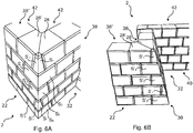
- Fig. 6A shows another view (seen from a different angle) of the outer 90-degree corner from the retaining wall 22 shown in Fig. 4A .
- Fig. 6B shows another view (seen from a different angle) of the retaining wall 22 shown in Fig. 4A .
- the sub-wall 38' comprises an outer corner formed by two adjacent sub-walls 38, 38' extending perpendicular to each other.
- the retaining wall 22 further comprises an inner corner 32 formed by two adjacent sub-walls 38, 40 extending perpendicular to each other.
- the outer 90-degree corner 30 comprises a right portion formed by five layers of cornerstones S 1 , S 2 , S 3 arranged one on top of each other (in order of the length of the stones), wherein a third outer cornerstone S 3 located at the bottom (is the lowermost cornerstone).
- the second lowest cornerstone S 1 is of the first type of cornerstones, whereas a cornerstone S 2 of the second type is placed on the top thereof.
- the inner 90-degree corner 32 comprises a left portion (see Fig. 4A ) formed by five layers of cornerstones S' 1 , S' 2 , S' 3 arranged one on top of each other (in order of the length of the stones), wherein a third outer cornerstone S' 3 is located at the bottom (is the lowermost cornerstone).
- the second lowest cornerstone S' 2 is of the second type of cornerstones, whereas a cornerstone S' 1 of the first type is placed on the top thereof.
- the small cornerstones S 1 , S' 1 are attached to their neighbouring stone.
- the sub-walls 38, 40 comprise an upper layer of stones having a free (exposed to the surroundings) top side 42 that extends horizontally.
- Fig. 7A shows a pallet 16 loaded with stones from a retaining wall system according to the invention.
- Three layers of stones are stacked on the top of each other.
- a band 50 has been tied around the top layer of stone, thereby preventing the stones from being displaced in a horizontal direction.
- the weight of the top layer of stone will push the underlying stones downward, thus preventing the stones from the two lower layers to be displaced relative to each other.
- the pallet 16 rests on a support 4.
- Fig. 7B shows a basis stone B corresponding to the ones that are stacked on the pallet shown in Fig. 7A .
- the basis stone B is oriented in the same way as the stones are mounted when forming part of a retaining wall. Seen from above, the base stones B on the pallet shown in Fig. 7A are oriented as illustrated in FIG. 7B . Therefore, the protruding structures 12, 12' can secure the formation of an air gap between the front side surface (facade) of the base stones and the rear side surface of an adjacent basis stone. In this way, the air gap allows for ventilation that prevents the formation of discolorations.
- Fig. 8A shows two adjacent basis stones B, B', in which the protruding structures 12, 12' cause the formation of an air gap 14 between the basis stones B, B'.
- This air gap 14 ensures ventilation which prevents the formation of discolorations.
- Fig. 8B shows a close-up view of the air gap 14 shown in Fig. 8A .
- the air gap 14 is provided between the two adjacent basis stones B, B'.
- Fig. 9A shows a retaining wall 22 made of stones from a retaining wall system according to the invention and Fig. 9B shows how a fourth outer cornerstone S 4 can be made from an outer cornerstone S 5 , having a length that is greater than the length of a basis stone so that the fourth cornerstone S 4 can be formed via truncation of the outer cornerstone S 5 e.g. by means of an angle grinder or a circular saw.
- the outer cornerstone S 5 having a length that is greater than the length of a basis stone comprises a 45-degree beveled edge configured to be joint with a corresponding outer corner portion to form a 90-degree corner.
- the retaining wall 22 comprises an outer 90-degree corner 30 formed by the two adjacent sub-walls 38, 38' extending perpendicular to each other and thus constituting a 90-degree corner comprising an outer corner edge 34.
- the retaining wall 22 comprises an inner 90-degree corner 32 formed by the two adjacent sub-walls 38, 40 extending perpendicular to each other and thus constituting a 90-degree corner comprising an inner corner edge 36.
- the outer 90-degree corner 30 is formed by five layers of cornerstones comprising a third outer cornerstone S 3 placed in the lowermost position.
- the second-lowermost cornerstone S 1 is of the first type of cornerstone, whereas a cornerstone S 2 of the second type is placed on the top of the second-lowermost cornerstone S 1 .
- This sequence of the cornerstones continues. Accordingly, the cornerstones (counted from the top) are arranged in the following order: S 4 , S 3 , S 2 , S 1 , S 3 .
- the upper cornerstone S 4 is not attached to its neighboring stone but is provided as a single independent fourth cornerstone S 4 .
- This fourth cornerstone S 4 is made from an outer cornerstone S 5 having a length that is longer than the length of a basis stone.
- the inner 90-degree corner 32 is formed by five layers of cornerstones comprising a third outer cornerstone S' 3 placed in the lowermost position.
- the second-lowermost cornerstone S' 2 is of the second type of cornerstone, whereas a cornerstone S' 1 of the first type is placed on the top of the second-lowermost cornerstone S' 2 .
- This sequence of the cornerstones continues. Accordingly, the cornerstones (counted from the top) are arranged in the following order: S' 2 , S' 3 , S' 1 , S' 2 , S' 3 . Accordingly, the user can apply the cornerstones in a fixed order.
- the three types of stones are easy to identify and recognize as the first cornerstone S' 1 has the smallest length, the second cornerstone S' 2 has the second least length while the third cornerstone S' 3 has the greatest length.
- the smallest inner cornerstone S' 1 may be attached to a neighboring stone.
- these cornerstones may be formed from an inner cornerstone S' 5 having a length that is longer than the length of a basis stone, wherein the inner cornerstone S' 5 comprises a 90-degree corner adapted to form an inner corner when being joined v with a corresponding cornerstone.
- Fig. 9C shows an inner cornerstone S' 5 (having a length that is longer than the length of a basis stone) before is being cut.
- a cutting line 52 corresponding to the total length of a basis stone B and a small inner cornerstone S' 1 is indicated.
- the inner cornerstone S' 5 (having a length that is longer than the length of a basis stone) is configured to bear against an adjacent sub-wall. It can be seen that the stone has a pre-defined angle ⁇ corresponding to the angle of the retaining wall relative to vertical (see e.g. Fig. 1A, Fig. 1B or Fig. 1C ).
Landscapes
- Engineering & Computer Science (AREA)
- Structural Engineering (AREA)
- Civil Engineering (AREA)
- Environmental & Geological Engineering (AREA)
- Architecture (AREA)
- Life Sciences & Earth Sciences (AREA)
- General Life Sciences & Earth Sciences (AREA)
- Mining & Mineral Resources (AREA)
- Paleontology (AREA)
- General Engineering & Computer Science (AREA)
- Physics & Mathematics (AREA)
- Electromagnetism (AREA)
- Retaining Walls (AREA)
Applications Claiming Priority (1)
| Application Number | Priority Date | Filing Date | Title |
|---|---|---|---|
| DKPA201900116A DK180282B1 (da) | 2019-01-29 | 2019-01-29 | Støttemurssystem |
Publications (2)
| Publication Number | Publication Date |
|---|---|
| EP3690146A1 true EP3690146A1 (fr) | 2020-08-05 |
| EP3690146B1 EP3690146B1 (fr) | 2022-08-03 |
Family
ID=69326373
Family Applications (1)
| Application Number | Title | Priority Date | Filing Date |
|---|---|---|---|
| EP20153793.3A Active EP3690146B1 (fr) | 2019-01-29 | 2020-01-27 | Système de paroi de retenue |
Country Status (2)
| Country | Link |
|---|---|
| EP (1) | EP3690146B1 (fr) |
| DK (1) | DK180282B1 (fr) |
Citations (4)
| Publication number | Priority date | Publication date | Assignee | Title |
|---|---|---|---|---|
| CH663437A5 (en) * | 1984-06-21 | 1987-12-15 | Carl Schiffer | Slope block |
| CH684012A5 (fr) * | 1990-10-15 | 1994-06-30 | Cornaz Et Fils S A | Jeu d'éléments en béton pour la construction de murs à sec et procédé de fabrication d'un tel jeu. |
| KR20040056946A (ko) * | 2002-12-24 | 2004-07-01 | 임철웅 | 텍솔 옹벽의 시공법 및 철망텍솔블록 |
| KR101864354B1 (ko) * | 2017-08-07 | 2018-07-13 | (주)케이에이 | 조립식 옹벽 구조체 |
-
2019
- 2019-01-29 DK DKPA201900116A patent/DK180282B1/da active IP Right Grant
-
2020
- 2020-01-27 EP EP20153793.3A patent/EP3690146B1/fr active Active
Patent Citations (4)
| Publication number | Priority date | Publication date | Assignee | Title |
|---|---|---|---|---|
| CH663437A5 (en) * | 1984-06-21 | 1987-12-15 | Carl Schiffer | Slope block |
| CH684012A5 (fr) * | 1990-10-15 | 1994-06-30 | Cornaz Et Fils S A | Jeu d'éléments en béton pour la construction de murs à sec et procédé de fabrication d'un tel jeu. |
| KR20040056946A (ko) * | 2002-12-24 | 2004-07-01 | 임철웅 | 텍솔 옹벽의 시공법 및 철망텍솔블록 |
| KR101864354B1 (ko) * | 2017-08-07 | 2018-07-13 | (주)케이에이 | 조립식 옹벽 구조체 |
Also Published As
| Publication number | Publication date |
|---|---|
| DK201900116A1 (da) | 2020-09-14 |
| EP3690146B1 (fr) | 2022-08-03 |
| DK180282B1 (da) | 2020-09-30 |
Similar Documents
| Publication | Publication Date | Title |
|---|---|---|
| US6874242B2 (en) | Dual spacing width tile spacer | |
| US8181415B2 (en) | Modular construction block | |
| US9670640B2 (en) | Retaining wall | |
| MX2007008003A (es) | Arreglos en bloque de mamposteria, unidades de muro y metodos. | |
| EP0374064A1 (fr) | Coffrage isolant pour mur en béton | |
| EP3690146B1 (fr) | Système de paroi de retenue | |
| EP0357950B1 (fr) | Ensemble d'éléments de construction en coin emboîtables | |
| US20140196392A1 (en) | Masonry units and structures formed therefrom | |
| AU2274000A (en) | Concrete wall formwork module | |
| FR3118979A1 (fr) | Panneau de construction et procédé de fabrication d’un mur au moyen d’un tel panneau | |
| KR101117176B1 (ko) | 기초 콘크리트 제작용 패널 및 이를 이용한 옹벽 시공 방법 | |
| WO2000045004A1 (fr) | Module de coffrage a paroi en beton | |
| CN111032976B (zh) | 构造模块及其使用方法 | |
| ES2248290T3 (es) | Metodo para el montaje de un andamio, andamio y partes del mismo. | |
| EP2358955B1 (fr) | Cadre de support | |
| EP3194676B1 (fr) | Unité d'infiltration en plastique, pluralité d'unités d'infiltration en plastique et procédé de fabrication d'une pluralité d'unités d'infiltration en plastique | |
| WO1992017674A1 (fr) | Construction d'un linteau avec des blocs de construction | |
| EP3414401B1 (fr) | Cage destinée à contenir des matériaux en pierre destinée à la fabrication de structures de murs en pierre sèche | |
| EP2927147B1 (fr) | Structure de support destinée à supporter un gros sac | |
| AU2021105780B4 (en) | Retaining Wall System and Blocks for Building the Retaining Wall | |
| EP3039197B1 (fr) | Drainage | |
| KR20130078950A (ko) | 경사조절용 옹벽블록 | |
| CN212078440U (zh) | 一种用于扁钢的钢格板 | |
| EP0930405A2 (fr) | Sous-structure pour système de plancher | |
| BE1025942A1 (nl) | Werkwijze voor het verbinden van twee balken |
Legal Events
| Date | Code | Title | Description |
|---|---|---|---|
| PUAI | Public reference made under article 153(3) epc to a published international application that has entered the european phase |
Free format text: ORIGINAL CODE: 0009012 |
|
| STAA | Information on the status of an ep patent application or granted ep patent |
Free format text: STATUS: THE APPLICATION HAS BEEN PUBLISHED |
|
| AK | Designated contracting states |
Kind code of ref document: A1 Designated state(s): AL AT BE BG CH CY CZ DE DK EE ES FI FR GB GR HR HU IE IS IT LI LT LU LV MC MK MT NL NO PL PT RO RS SE SI SK SM TR |
|
| AX | Request for extension of the european patent |
Extension state: BA ME |
|
| STAA | Information on the status of an ep patent application or granted ep patent |
Free format text: STATUS: REQUEST FOR EXAMINATION WAS MADE |
|
| 17P | Request for examination filed |
Effective date: 20210205 |
|
| RBV | Designated contracting states (corrected) |
Designated state(s): AL AT BE BG CH CY CZ DE DK EE ES FI FR GB GR HR HU IE IS IT LI LT LU LV MC MK MT NL NO PL PT RO RS SE SI SK SM TR |
|
| GRAP | Despatch of communication of intention to grant a patent |
Free format text: ORIGINAL CODE: EPIDOSNIGR1 |
|
| STAA | Information on the status of an ep patent application or granted ep patent |
Free format text: STATUS: GRANT OF PATENT IS INTENDED |
|
| INTG | Intention to grant announced |
Effective date: 20220307 |
|
| GRAS | Grant fee paid |
Free format text: ORIGINAL CODE: EPIDOSNIGR3 |
|
| GRAA | (expected) grant |
Free format text: ORIGINAL CODE: 0009210 |
|
| STAA | Information on the status of an ep patent application or granted ep patent |
Free format text: STATUS: THE PATENT HAS BEEN GRANTED |
|
| AK | Designated contracting states |
Kind code of ref document: B1 Designated state(s): AL AT BE BG CH CY CZ DE DK EE ES FI FR GB GR HR HU IE IS IT LI LT LU LV MC MK MT NL NO PL PT RO RS SE SI SK SM TR |
|
| REG | Reference to a national code |
Ref country code: AT Ref legal event code: REF Ref document number: 1508852 Country of ref document: AT Kind code of ref document: T Effective date: 20220815 Ref country code: CH Ref legal event code: EP |
|
| REG | Reference to a national code |
Ref country code: DE Ref legal event code: R096 Ref document number: 602020004253 Country of ref document: DE |
|
| REG | Reference to a national code |
Ref country code: IE Ref legal event code: FG4D |
|
| REG | Reference to a national code |
Ref country code: SE Ref legal event code: TRGR |
|
| REG | Reference to a national code |
Ref country code: LT Ref legal event code: MG9D |
|
| REG | Reference to a national code |
Ref country code: NL Ref legal event code: MP Effective date: 20220803 |
|
| REG | Reference to a national code |
Ref country code: NO Ref legal event code: T2 Effective date: 20220803 |
|
| PG25 | Lapsed in a contracting state [announced via postgrant information from national office to epo] |
Ref country code: RS Free format text: LAPSE BECAUSE OF FAILURE TO SUBMIT A TRANSLATION OF THE DESCRIPTION OR TO PAY THE FEE WITHIN THE PRESCRIBED TIME-LIMIT Effective date: 20220803 Ref country code: PT Free format text: LAPSE BECAUSE OF FAILURE TO SUBMIT A TRANSLATION OF THE DESCRIPTION OR TO PAY THE FEE WITHIN THE PRESCRIBED TIME-LIMIT Effective date: 20221205 Ref country code: NL Free format text: LAPSE BECAUSE OF FAILURE TO SUBMIT A TRANSLATION OF THE DESCRIPTION OR TO PAY THE FEE WITHIN THE PRESCRIBED TIME-LIMIT Effective date: 20220803 Ref country code: LV Free format text: LAPSE BECAUSE OF FAILURE TO SUBMIT A TRANSLATION OF THE DESCRIPTION OR TO PAY THE FEE WITHIN THE PRESCRIBED TIME-LIMIT Effective date: 20220803 Ref country code: LT Free format text: LAPSE BECAUSE OF FAILURE TO SUBMIT A TRANSLATION OF THE DESCRIPTION OR TO PAY THE FEE WITHIN THE PRESCRIBED TIME-LIMIT Effective date: 20220803 Ref country code: FI Free format text: LAPSE BECAUSE OF FAILURE TO SUBMIT A TRANSLATION OF THE DESCRIPTION OR TO PAY THE FEE WITHIN THE PRESCRIBED TIME-LIMIT Effective date: 20220803 Ref country code: ES Free format text: LAPSE BECAUSE OF FAILURE TO SUBMIT A TRANSLATION OF THE DESCRIPTION OR TO PAY THE FEE WITHIN THE PRESCRIBED TIME-LIMIT Effective date: 20220803 |
|
| REG | Reference to a national code |
Ref country code: AT Ref legal event code: MK05 Ref document number: 1508852 Country of ref document: AT Kind code of ref document: T Effective date: 20220803 |
|
| PG25 | Lapsed in a contracting state [announced via postgrant information from national office to epo] |
Ref country code: PL Free format text: LAPSE BECAUSE OF FAILURE TO SUBMIT A TRANSLATION OF THE DESCRIPTION OR TO PAY THE FEE WITHIN THE PRESCRIBED TIME-LIMIT Effective date: 20220803 Ref country code: IS Free format text: LAPSE BECAUSE OF FAILURE TO SUBMIT A TRANSLATION OF THE DESCRIPTION OR TO PAY THE FEE WITHIN THE PRESCRIBED TIME-LIMIT Effective date: 20221203 Ref country code: HR Free format text: LAPSE BECAUSE OF FAILURE TO SUBMIT A TRANSLATION OF THE DESCRIPTION OR TO PAY THE FEE WITHIN THE PRESCRIBED TIME-LIMIT Effective date: 20220803 Ref country code: GR Free format text: LAPSE BECAUSE OF FAILURE TO SUBMIT A TRANSLATION OF THE DESCRIPTION OR TO PAY THE FEE WITHIN THE PRESCRIBED TIME-LIMIT Effective date: 20221104 |
|
| PG25 | Lapsed in a contracting state [announced via postgrant information from national office to epo] |
Ref country code: SM Free format text: LAPSE BECAUSE OF FAILURE TO SUBMIT A TRANSLATION OF THE DESCRIPTION OR TO PAY THE FEE WITHIN THE PRESCRIBED TIME-LIMIT Effective date: 20220803 Ref country code: RO Free format text: LAPSE BECAUSE OF FAILURE TO SUBMIT A TRANSLATION OF THE DESCRIPTION OR TO PAY THE FEE WITHIN THE PRESCRIBED TIME-LIMIT Effective date: 20220803 Ref country code: DK Free format text: LAPSE BECAUSE OF FAILURE TO SUBMIT A TRANSLATION OF THE DESCRIPTION OR TO PAY THE FEE WITHIN THE PRESCRIBED TIME-LIMIT Effective date: 20220803 Ref country code: CZ Free format text: LAPSE BECAUSE OF FAILURE TO SUBMIT A TRANSLATION OF THE DESCRIPTION OR TO PAY THE FEE WITHIN THE PRESCRIBED TIME-LIMIT Effective date: 20220803 Ref country code: AT Free format text: LAPSE BECAUSE OF FAILURE TO SUBMIT A TRANSLATION OF THE DESCRIPTION OR TO PAY THE FEE WITHIN THE PRESCRIBED TIME-LIMIT Effective date: 20220803 |
|
| REG | Reference to a national code |
Ref country code: DE Ref legal event code: R097 Ref document number: 602020004253 Country of ref document: DE |
|
| PG25 | Lapsed in a contracting state [announced via postgrant information from national office to epo] |
Ref country code: SK Free format text: LAPSE BECAUSE OF FAILURE TO SUBMIT A TRANSLATION OF THE DESCRIPTION OR TO PAY THE FEE WITHIN THE PRESCRIBED TIME-LIMIT Effective date: 20220803 Ref country code: EE Free format text: LAPSE BECAUSE OF FAILURE TO SUBMIT A TRANSLATION OF THE DESCRIPTION OR TO PAY THE FEE WITHIN THE PRESCRIBED TIME-LIMIT Effective date: 20220803 |
|
| PLBE | No opposition filed within time limit |
Free format text: ORIGINAL CODE: 0009261 |
|
| STAA | Information on the status of an ep patent application or granted ep patent |
Free format text: STATUS: NO OPPOSITION FILED WITHIN TIME LIMIT |
|
| PG25 | Lapsed in a contracting state [announced via postgrant information from national office to epo] |
Ref country code: AL Free format text: LAPSE BECAUSE OF FAILURE TO SUBMIT A TRANSLATION OF THE DESCRIPTION OR TO PAY THE FEE WITHIN THE PRESCRIBED TIME-LIMIT Effective date: 20220803 |
|
| 26N | No opposition filed |
Effective date: 20230504 |
|
| PG25 | Lapsed in a contracting state [announced via postgrant information from national office to epo] |
Ref country code: SI Free format text: LAPSE BECAUSE OF FAILURE TO SUBMIT A TRANSLATION OF THE DESCRIPTION OR TO PAY THE FEE WITHIN THE PRESCRIBED TIME-LIMIT Effective date: 20220803 |
|
| REG | Reference to a national code |
Ref country code: CH Ref legal event code: PL |
|
| PG25 | Lapsed in a contracting state [announced via postgrant information from national office to epo] |
Ref country code: LU Free format text: LAPSE BECAUSE OF NON-PAYMENT OF DUE FEES Effective date: 20230127 |
|
| REG | Reference to a national code |
Ref country code: BE Ref legal event code: MM Effective date: 20230131 |
|
| PG25 | Lapsed in a contracting state [announced via postgrant information from national office to epo] |
Ref country code: LI Free format text: LAPSE BECAUSE OF NON-PAYMENT OF DUE FEES Effective date: 20230131 Ref country code: CH Free format text: LAPSE BECAUSE OF NON-PAYMENT OF DUE FEES Effective date: 20230131 |
|
| PG25 | Lapsed in a contracting state [announced via postgrant information from national office to epo] |
Ref country code: BE Free format text: LAPSE BECAUSE OF NON-PAYMENT OF DUE FEES Effective date: 20230131 |
|
| PG25 | Lapsed in a contracting state [announced via postgrant information from national office to epo] |
Ref country code: IE Free format text: LAPSE BECAUSE OF NON-PAYMENT OF DUE FEES Effective date: 20230127 |
|
| PG25 | Lapsed in a contracting state [announced via postgrant information from national office to epo] |
Ref country code: IT Free format text: LAPSE BECAUSE OF FAILURE TO SUBMIT A TRANSLATION OF THE DESCRIPTION OR TO PAY THE FEE WITHIN THE PRESCRIBED TIME-LIMIT Effective date: 20220803 |
|
| PG25 | Lapsed in a contracting state [announced via postgrant information from national office to epo] |
Ref country code: MC Free format text: LAPSE BECAUSE OF FAILURE TO SUBMIT A TRANSLATION OF THE DESCRIPTION OR TO PAY THE FEE WITHIN THE PRESCRIBED TIME-LIMIT Effective date: 20220803 |
|
| PG25 | Lapsed in a contracting state [announced via postgrant information from national office to epo] |
Ref country code: MC Free format text: LAPSE BECAUSE OF FAILURE TO SUBMIT A TRANSLATION OF THE DESCRIPTION OR TO PAY THE FEE WITHIN THE PRESCRIBED TIME-LIMIT Effective date: 20220803 |
|
| PG25 | Lapsed in a contracting state [announced via postgrant information from national office to epo] |
Ref country code: BG Free format text: LAPSE BECAUSE OF FAILURE TO SUBMIT A TRANSLATION OF THE DESCRIPTION OR TO PAY THE FEE WITHIN THE PRESCRIBED TIME-LIMIT Effective date: 20220803 |
|
| PG25 | Lapsed in a contracting state [announced via postgrant information from national office to epo] |
Ref country code: BG Free format text: LAPSE BECAUSE OF FAILURE TO SUBMIT A TRANSLATION OF THE DESCRIPTION OR TO PAY THE FEE WITHIN THE PRESCRIBED TIME-LIMIT Effective date: 20220803 |
|
| PG25 | Lapsed in a contracting state [announced via postgrant information from national office to epo] |
Ref country code: CY Free format text: LAPSE BECAUSE OF FAILURE TO SUBMIT A TRANSLATION OF THE DESCRIPTION OR TO PAY THE FEE WITHIN THE PRESCRIBED TIME-LIMIT; INVALID AB INITIO Effective date: 20200127 |
|
| PG25 | Lapsed in a contracting state [announced via postgrant information from national office to epo] |
Ref country code: HU Free format text: LAPSE BECAUSE OF FAILURE TO SUBMIT A TRANSLATION OF THE DESCRIPTION OR TO PAY THE FEE WITHIN THE PRESCRIBED TIME-LIMIT; INVALID AB INITIO Effective date: 20200127 |
|
| PG25 | Lapsed in a contracting state [announced via postgrant information from national office to epo] |
Ref country code: TR Free format text: LAPSE BECAUSE OF FAILURE TO SUBMIT A TRANSLATION OF THE DESCRIPTION OR TO PAY THE FEE WITHIN THE PRESCRIBED TIME-LIMIT Effective date: 20220803 |
|
| PGFP | Annual fee paid to national office [announced via postgrant information from national office to epo] |
Ref country code: SE Payment date: 20260127 Year of fee payment: 7 |
|
| PGFP | Annual fee paid to national office [announced via postgrant information from national office to epo] |
Ref country code: GB Payment date: 20260127 Year of fee payment: 7 |
|
| PGFP | Annual fee paid to national office [announced via postgrant information from national office to epo] |
Ref country code: NO Payment date: 20260128 Year of fee payment: 7 Ref country code: DE Payment date: 20260128 Year of fee payment: 7 |
|
| PGFP | Annual fee paid to national office [announced via postgrant information from national office to epo] |
Ref country code: FR Payment date: 20260126 Year of fee payment: 7 |