EP3690302A1 - Système amélioré de sécurisation d'accès permettant de sécuriser une machine ou une installation - Google Patents
Système amélioré de sécurisation d'accès permettant de sécuriser une machine ou une installation Download PDFInfo
- Publication number
- EP3690302A1 EP3690302A1 EP20152330.5A EP20152330A EP3690302A1 EP 3690302 A1 EP3690302 A1 EP 3690302A1 EP 20152330 A EP20152330 A EP 20152330A EP 3690302 A1 EP3690302 A1 EP 3690302A1
- Authority
- EP
- European Patent Office
- Prior art keywords
- blocking element
- blocking
- base body
- receiver
- light pulse
- Prior art date
- Legal status (The legal status is an assumption and is not a legal conclusion. Google has not performed a legal analysis and makes no representation as to the accuracy of the status listed.)
- Granted
Links
Images





Classifications
-
- F—MECHANICAL ENGINEERING; LIGHTING; HEATING; WEAPONS; BLASTING
- F16—ENGINEERING ELEMENTS AND UNITS; GENERAL MEASURES FOR PRODUCING AND MAINTAINING EFFECTIVE FUNCTIONING OF MACHINES OR INSTALLATIONS; THERMAL INSULATION IN GENERAL
- F16P—SAFETY DEVICES IN GENERAL; SAFETY DEVICES FOR PRESSES
- F16P3/00—Safety devices acting in conjunction with the control or operation of a machine; Control arrangements requiring the simultaneous use of two or more parts of the body
- F16P3/12—Safety devices acting in conjunction with the control or operation of a machine; Control arrangements requiring the simultaneous use of two or more parts of the body with means, e.g. feelers, which in case of the presence of a body part of a person in or near the danger zone influence the control or operation of the machine
- F16P3/14—Safety devices acting in conjunction with the control or operation of a machine; Control arrangements requiring the simultaneous use of two or more parts of the body with means, e.g. feelers, which in case of the presence of a body part of a person in or near the danger zone influence the control or operation of the machine the means being photocells or other devices sensitive without mechanical contact
- F16P3/144—Safety devices acting in conjunction with the control or operation of a machine; Control arrangements requiring the simultaneous use of two or more parts of the body with means, e.g. feelers, which in case of the presence of a body part of a person in or near the danger zone influence the control or operation of the machine the means being photocells or other devices sensitive without mechanical contact using light grids
-
- B—PERFORMING OPERATIONS; TRANSPORTING
- B30—PRESSES
- B30B—PRESSES IN GENERAL
- B30B15/00—Details of, or accessories for, presses; Auxiliary measures in connection with pressing
- B30B15/28—Arrangements for preventing distortion of, or damage to, presses or parts thereof
- B30B15/285—Arrangements for preventing distortion of, or damage to, presses or parts thereof preventing a full press stroke if there is an obstruction in the working area
-
- F—MECHANICAL ENGINEERING; LIGHTING; HEATING; WEAPONS; BLASTING
- F16—ENGINEERING ELEMENTS AND UNITS; GENERAL MEASURES FOR PRODUCING AND MAINTAINING EFFECTIVE FUNCTIONING OF MACHINES OR INSTALLATIONS; THERMAL INSULATION IN GENERAL
- F16P—SAFETY DEVICES IN GENERAL; SAFETY DEVICES FOR PRESSES
- F16P3/00—Safety devices acting in conjunction with the control or operation of a machine; Control arrangements requiring the simultaneous use of two or more parts of the body
- F16P3/08—Safety devices acting in conjunction with the control or operation of a machine; Control arrangements requiring the simultaneous use of two or more parts of the body in connection with the locking of doors, covers, guards, or like members giving access to moving machine parts
-
- F—MECHANICAL ENGINEERING; LIGHTING; HEATING; WEAPONS; BLASTING
- F16—ENGINEERING ELEMENTS AND UNITS; GENERAL MEASURES FOR PRODUCING AND MAINTAINING EFFECTIVE FUNCTIONING OF MACHINES OR INSTALLATIONS; THERMAL INSULATION IN GENERAL
- F16P—SAFETY DEVICES IN GENERAL; SAFETY DEVICES FOR PRESSES
- F16P3/00—Safety devices acting in conjunction with the control or operation of a machine; Control arrangements requiring the simultaneous use of two or more parts of the body
- F16P3/12—Safety devices acting in conjunction with the control or operation of a machine; Control arrangements requiring the simultaneous use of two or more parts of the body with means, e.g. feelers, which in case of the presence of a body part of a person in or near the danger zone influence the control or operation of the machine
- F16P3/14—Safety devices acting in conjunction with the control or operation of a machine; Control arrangements requiring the simultaneous use of two or more parts of the body with means, e.g. feelers, which in case of the presence of a body part of a person in or near the danger zone influence the control or operation of the machine the means being photocells or other devices sensitive without mechanical contact
- F16P3/147—Safety devices acting in conjunction with the control or operation of a machine; Control arrangements requiring the simultaneous use of two or more parts of the body with means, e.g. feelers, which in case of the presence of a body part of a person in or near the danger zone influence the control or operation of the machine the means being photocells or other devices sensitive without mechanical contact using electro-magnetic technology, e.g. tags or radar
-
- G—PHYSICS
- G01—MEASURING; TESTING
- G01V—GEOPHYSICS; GRAVITATIONAL MEASUREMENTS; DETECTING MASSES OR OBJECTS; TAGS
- G01V8/00—Prospecting or detecting by optical means
- G01V8/10—Detecting, e.g. by using light barriers
- G01V8/20—Detecting, e.g. by using light barriers using multiple transmitters or receivers
Definitions
- the present invention relates to an access security system and a method for securing access to a machine or system arranged in a security area.
- the access security system has a sensor device and a control device.
- the sensor device has an optical transmitter and an optical receiver.
- the optical transmitter is set up to send a light pulse to the optical receiver.
- the sensor device is designed to generate a sensor signal based on the reception of the light pulses by the receiver.
- the control device is designed to read out the sensor signal and to control the machine or system arranged in the safety area, taking into account the sensor signal.
- the publication shows DE 10 2012 111 433 A1 an optoelectronic protective device for securing a danger point, with an optical transmitter and an optical receiver, which are arranged at a spatial distance from one another.
- the system After leaving the protective field, e.g. running out of the protective field and running into the danger zone, the system must remain in a safe state (OFF). This can be seen through a software lock in the light curtain or in the safety controller.
- a restart is only possible if a reset signal or restart signal is explicitly provided. It is important that a restart button for providing the reset signal is arranged so that the danger area is visible and an operator can ensure that the system can start up again safely.
- the restart button can be pressed to restart the system in an unauthorized case.
- this problem exists in the case when there is a special operating case of the system, in particular maintenance, repair, commissioning or adjustment of the system.
- a second person can press the restart button while a first person is still in the danger zone and is covered by parts of the system and is not visible from the outside.
- the first could be Person is on the floor or in the machine for repair or maintenance purposes.
- the first person is no longer in the danger zone, but in the meantime another person has entered the danger zone to search for the user, with the restart of the system being started by a third person or by the first person.
- solutions to the problem described above are known in the prior art. These solutions propose to provide additional means to be able to detect a person in the danger zone.
- separate non-contact protective devices can be used. These include, in particular, light grids in a horizontal or horizontal orientation, scanners in the danger zone, additional floor mats or a secure camera system.
- an object of the present invention to provide an access security system and method with expanded security functions and increased manipulation protection.
- an access protection system and method which further ensures high security, requires less programming and wiring, is inexpensive and ecological in production and use and enables simple integration and handling.
- the access security system described at the outset is further developed such that the access security system furthermore has a locking device with a base body and a blocking element arranged thereon.
- the blocking element can be moved relative to the base body from a release position into a blocking position in which the blocking element is arranged in a beam path of the light pulse between the transmitter and the receiver in order to block the reception of the light pulse.
- the locking device can be locked in the locked position by means of a securing element.
- a sensor device for securing access to a machine or system arranged in a security area comprising an optical transmitter and an optical receiver, the optical transmitter being set up to send a light pulse to the optical receiver and the sensor device being set up for this to generate a sensor signal based on the reception of the light pulse by the receiver, on the basis of which the machine or system arranged in the security area can be controlled, in particular switched off, wherein a locking device with a base body and a blocking element arranged thereon is arranged on the sensor device , wherein the blocking element relative to the base body can be brought from a release position into a blocking position in which the blocking element is arranged in a beam path of the light pulse between the transmitter and the receiver in order to de s to block the light beam, and the locking device can be locked in the locked position by means of a securing element.
- a locking device for a sensor device which monitors access to a machine or system arranged in a security area and has an optical transmitter and an optical receiver which can be brought into interaction with one another by exchanging light pulses and thereby generate a sensor signal, the locking device having a base body and a blocking element arranged thereon, the blocking element being able to be moved from the release position into a blocking position relative to the base body, in which the blocking element is arranged in a beam path of the light pulses between the transmitter and the receiver and the like Interaction prevented, and wherein the locking device can be locked in the locked position by means of a securing element.
- safety area is to be understood as the area which surrounds the system or machine and which is protected by the sensor device.
- the safety area can be a danger area in which people are not allowed to stay while the machine or system is in operation, because the machine or system due to its automatic operation, it poses a danger to people who are in the danger zone.
- the security area can be understood, for example, as an essentially closed area that is only accessible via an access.
- the sensor device can be arranged in this access for the purpose of access control.
- the security area can also have two or more accesses, and each access can be secured separately. For example, a sensor device can be provided for each access.
- the sensor device can recognize whether a person or an object is in the entrance to the security area or is passing through the entrance. If a person or an object is in the access, the reception of the light pulse is blocked, i.e. the light pulse does not reach the receiver. This enables the sensor device to determine whether a person or an object is in the access.
- the generated light pulse propagates along a beam path from the transmitter to the receiver. In other words, the light pulse forms a light beam along the beam path.
- the sensor device can also be designed to perform a plurality of light pulses sequentially, i.e. to be transmitted at different times or in time intervals, one after the other.
- the sensor device generates the sensor signal based on the reception of the light pulse.
- the sensor signal can contain, for example, information about whether the receiver has received a transmitted light pulse or not.
- the sensor signal can also contain information about whether a person or an object has been recognized in the access.
- the present invention is based on the idea of providing an additional locking device by means of which the security area can be secured, in particular in the case of special operation of the machine or system.
- the locking device secures the security area over the entire duration of a special operation of the machine or system.
- the locking device has a blocking element.
- the blocking element can be introduced into a beam path of the light pulse between the transmitter and receiver in order to block reception of the light pulse. This can prevent unauthorized starting or an independent start-up of the machine or system, for example during a special operating case.
- the locking element can be brought from the release position into the blocking position to secure the machine or system.
- the blocking element In the release position, the blocking element is arranged outside the beam path of the light pulse. In the blocking position, the blocking element is arranged within the beam path of the light pulse.
- the term "bringable" means that the position or the orientation of the blocking element can be changed relative to the base body.
- the blocking element can be rotated and / or moved relative to the base body.
- the blocking element is rotated about an axis of rotation or displaced along a rail.
- the base body can define the axis of rotation and / or the rail can be formed thereon.
- the locking device can be locked in the locked position by means of the securing element.
- lockable is to be understood to mean that means are provided which prevent the blocking element from being transferred out of the locked position.
- lockable can mean in particular lockable.
- a padlock can be provided as a means of locking. The padlock locks or locks the blocking element in its locked position.
- the blocking element cannot be moved from the locked position into the release position without releasing the locking provided by the securing element.
- a user must take a conscious action to enable the machine or system to restart. This prevents, for example, that a third party can unintentionally restart the machine or system as long as a user is in the special operation Security area.
- the mechanical design also makes manipulation of the blocking device more difficult.
- the locking device is ecological in the production and application. Furthermore, the locking device is simple to integrate, in particular in existing systems, and simple to use.
- the blocking element can be pivoted mechanically relative to the base body from the release position into the blocking position in a direction of rotation about a pivot axis.
- the blocking element is brought from the release position into the blocking position instead of being pivoted by a linear displacement.
- Both the displacement and the pivoting of the blocking element can either be done automatically at the push of a button, for example with the aid of an electric motor, or mechanically by hand.
- Mechanical pivoting by hand is a simple and inexpensive solution.
- the blocking element is preferably pivoted through 90 ° in order to bring it out of the release position into its blocking position or vice versa.
- the longitudinal direction of the blocking element includes an angle of preferably 90 ° with the same in the blocking position compared to the release position.
- the pivot axis is arranged parallel or perpendicular to the beam path of the light pulse.
- the blocking element is rotated about the pivot axis into the beam path of the light pulse.
- the pivot axis preferably extends away from the base body. If the pivot axis is arranged perpendicular to the beam path of the light pulse, the blocking element is folded into the beam path of the light pulse about the pivot axis.
- the pivot axis is preferably arranged parallel to or along the base body. The choice of the arrangement of the pivot axis depends on the available installation space in the specific application, since the blocking element in the release position extends from the base body in different directions depending on the arrangement of the pivot axis.
- the securing element is designed to connect the base body and the blocking element in the locking position in a rotationally fixed manner to one another.
- a handle for pivoting the blocking element about the pivot axis by hand is provided on the blocking element, in particular wherein the handle extends essentially parallel to the pivot axis, in particular essentially along the pivot axis.
- the blocking element can be turned or pivoted relatively easily.
- This handle can also be ergonomically shaped for easy and comfortable handling. By attaching the handle along the pivot axis of the locking lever, the force required for pivoting or twisting can be very easily transmitted to the blocking element.
- the blocking element itself is preferably designed in the form of a plate, so that in the blocking position it can be arranged as large as possible in the beam path of the light pulse between the transmitter and the receiver.
- the blocking element is coupled to the base body via a spring element which is arranged along the pivot axis and which in the release position and / or in the blocking position exerts a spring force which presses the blocking element against the base body.
- a mechanical compression spring can be used as the spring element.
- a pneumatic or hydraulic spring element would also be conceivable.
- the spring force exerted by the spring element on the blocking element essentially has the purpose of preventing the blocking element from being unintentionally released from its release position and / or from its blocking position. It presses the blocking element against the base body of the locking device. In order to be able to pivot the blocking element from the blocking position into the release position or vice versa, the operator must therefore first slightly raise the blocking element against the action of the spring force. The spring force exerted by the spring element should therefore not be too great.
- the blocking element can be locked to the base body in the release position and / or in the blocking position.
- the blocking element can preferably be latched to the base body both in the release position and in the blocking position.
- Such locking of the blocking element offers, in addition to the spring element mentioned above, protection against unintentional pivoting of the blocking element out of the blocking position or the release position.
- the positions of the blocking element in the release position and the locking position are also precisely defined. This simplifies handling for the operator.
- a first and a second recess are provided on the base body, the blocking element being locked in the release position by being arranged in the first recess and being locked in the blocking position by being arranged in the second recess.
- the two recesses provided in the base body are preferably arranged orthogonally to one another.
- the locking device further has a receptacle for the securing element, the securing element, inserted into the receptacle, holding the blocking element in its locked position, in particular wherein the securing element can be locked.
- the blocking element can be locked in its blocking position in a simple manner.
- the securing element is preferably designed as a padlock. A shackle of the padlock can then be passed through the receptacle of the blocking element in order to lock the blocking element in the locked position.
- the receptacle for the lockable securing element is designed as a bore in the blocking element.
- a padlock used as a lockable security element can thus be inserted directly into the hole provided in the blocking element.
- the bore is preferably only accessible when the blocking element is in the locked position.
- a padlock can therefore only be attached to the locking device when the blocking element is in the locked position.
- the position of the bore should also be selected so that the blocking element can no longer be moved or pivoted from the locked position into the release position when a padlock is inserted into the bore. This is prevented by the padlock colliding with the base body of the locking device when an attempt is made to pivot the lever.
- said bore is preferably arranged in the region of one end of the plate-shaped blocking element.
- a recess is provided on the base body, which is at least partially aligned with the bore provided in the blocking element in the blocking position of the blocking element.
- This recess can either be provided as a bore or as a type of notch in the base body.
- the fact that this recess is aligned with the hole provided in the blocking element in the blocking position of the blocking element results in a kind of positive locking between the shackle of the padlock and the hole in the blocking element and the recess on the base body when a padlock is inserted into the hole.
- the padlock In the locked position of the blocking element, the padlock is therefore not only inserted into the hole in the blocking element, but also into the recess in the base body. If the hole and the recess lie exactly one above the other in the locked position, pivoting of the blocking element when the padlock is inserted is no longer possible without this Padlock or destroy the locking device. The additional security provided by the locking device cannot be manipulated unintentionally.
- two holes are provided in the blocking element as receptacles for each lockable securing element and two recesses are provided on the base body, which at least partially in the blocking position of the blocking element with the holes provided in the blocking element aligned, the securing elements, inserted into the respective receptacle, hold the blocking element in its locked position.
- the locking lever has two slots for a padlock, so to speak.
- a first operator secures the access security system with a first padlock when entering the security area. If a second person then enters the security area, they can also secure the blocking element in the locked position by inserting or hanging a second padlock in the second hole in the blocking element. If the first operator then leaves the security area, the second padlock immediately recognizes that there is another person in the security area. The two operators can therefore only bring the blocking element back into its release position by releasing both padlocks from the blocking element. It would therefore be ensured even with two operators that neither of the two is in the safety area when the machine or system is put into operation again. It goes without saying that, depending on the number of potential operators, more than two holes or receptacles for padlocks can of course also be provided on the locking device.
- the base body is arranged on the transmitter or on the receiver, in particular wherein the base body can be rigidly connected to the transmitter or the receiver.
- the base body is thus arranged on the transmitter side or on the receiver side. Due to the rigid connection to the transmitter or the receiver, the blocking element can in particular be moved relative to the transmitter or receiver, that is to say relative to the beam path of the light pulse.
- the transmitter and / or the receiver are preferably arranged on opposite sides of the access. It can be provided here that a bar is attached to each side of the access, the transmitter and the receiver being arranged in each of the bars.
- the base body of the locking device can either be mounted directly or via a coupling element on one of the strips.
- the sensor device has a multiplicity of optical transmitters and corresponding optical receivers, the blocking element being arranged in its blocking position in at least two beam paths of the light pulses between the transmitters and the receivers.
- Blocking two beam paths has the advantage that redundant protection is created in the event of an error. For example, a blocked receiver could erroneously detect a light signal, although the blocking element blocks a corresponding beam path. Furthermore, a blocked receiver could also transmit an incorrect signal to the control device due to a defect or manipulation.
- FIGS. 1 and 2nd show a first embodiment of an access security system 10.
- Fig. 1 the basic structure of the access security system 10 is shown.
- Fig. 2 shows a detailed view of the access security system 10, in which a locking mechanism for additional security of the access security system 10 is shown.
- the access security system 10 is provided for securing a system or machine 14 arranged in a security area 12. Access 20 to security area 12 is monitored by access security system 10. If a person enters the security area 12, this is recognized with the aid of the access security system 10 and the system or machine 14 arranged in the security area 12 is brought into a safe state for the person. For example, the system or machine 14 can be switched off, in particular by interrupting the power supply.
- the access security system 10 has a sensor device 16.
- the sensor device 16 is arranged at the access 20 to the security area 12.
- the sensor device 16 has an optical transmitter 22 and an optical receiver 24.
- the optical transmitter 22 and the optical receiver 24 are arranged at a spatial distance 26 from one another.
- the transmitter 22 and the receiver 24 are preferably arranged on opposite sides of the access 20.
- the optical transmitter 22 generates a light pulse and sends it along a beam path 28 to the optical receiver 24. In other words, the light pulse forms along the beam path 28 from a light beam.
- the sensor device 16 is designed to generate a sensor signal based on the reception of the light pulse by the receiver 24.
- the sensor signal thus contains the information as to whether the light pulse has reached the receiver 24.
- the optical transmitter 22 can preferably generate light pulses at time intervals and sends them along a beam path 28 to the optical receiver 24.
- the sensor device 16 can also have a multiplicity of optical transmitters 22 and corresponding optical receivers 24.
- the plurality of transmitters 22 and the plurality of receivers 24 can each be arranged in a bar. The two strips can be arranged on opposite sides of the access 20.
- Each transmitter 22 sends a light pulse along a beam path 28 to the corresponding receiver 24.
- the light pulses form light beams between the respective transmitters 22 and receivers 24.
- the individual light beams span a so-called light grid between the transmitters 22 and receivers 24.
- the light grid is arranged in the entrance of the security area 12 such that a person briefly interrupts at least one light beam when entering the security area, i.e.
- the sensor device 16 can generate a separate sensor signal for each transmitter-receiver pair. Alternatively, the sensor device 16 can generate a sensor signal that contains the information as to whether a receiver 24 of the plurality of receivers has not received the corresponding light pulse.
- the access security system 10 also has a control device 18.
- the control device 18 can be connected to the optical transmitter 22 via a line 30 and to the optical receiver 24 via a line 32.
- a line 30, 32 can be provided for each transmitter 22 and receiver 24.
- a line 30 can be provided for all transmitters 22 and a line 32 for all receivers.
- the control device 18 is designed to read out the sensor signal and to control the system or machine 14 arranged in the security area 12, taking into account the sensor signal. For example, control device 18 can stop the system or machine 14 if a light pulse has been blocked. Alternatively, the control device 18 can transfer the system or machine 14 into a safe state.
- control device 18 can stop the power supply 36 to the plant or machine 14 to stop the plant or machine 14.
- control device 18 is connected to contactors 34, which are arranged in the electrical connection between the power supply 36 and the system or machine 14. If a light beam is interrupted, the control device 18 uses the contactors 34 to interrupt the power supply 36 to the system or machine 14 and thus brings the system or machine 14 to a standstill.
- the control of the contactors 34 is configured redundantly in accordance with the current standards.
- the control device 18 can control the optical transmitter 22.
- the control device 18 can be provided, for example, that the control device 18 generates a test signal and sends it to the optical transmitter (s) 22.
- the transmitter (s) 22 transmit the test signal to the receiver 24 using the respectively associated pulsed light beam.
- the test signal can be modulated onto the respective pulsed light beam.
- the receiver (s) 24 receive the test signal and send it back to the control device 18.
- the control device 18 compares the received test signal with the original test signal.
- a pulsed light beam is briefly interrupted, so that the test signal does not reach the receiver 24, or not completely. If an incomplete signal is returned by a receiver 24, the control device 18 recognizes this when comparing the outgoing signal with the incoming signal and then disconnects the power supply 36 to the system or machine 14 by means of the contactors 34.
- test signal can also be generated and evaluated in the sensor device.
- the sensor signal then only contains the information as to whether a light beam from a transmitter-receiver pair has been interrupted.
- the access security system 10 furthermore, as in FIG Fig. 2 shown, a locking device 40.
- the locking device 40 is an additional mechanical component that can be arranged on or in the access 20 of the security area 12.
- the locking device 40 forms an additional locking mechanism for additional security of the access security system 10.
- this locking mechanism can serve to secure the security area 12 in a special operating case of the system or machine 14.
- Fig. 2 shows two embodiments (A) and (B) of the locking device 40.
- the embodiments (A) and (B) have essentially the same components and differ essentially only in the different movement of the locking mechanism.
- the locking device 40 has a base body 42 and a blocking element 44.
- the blocking element 44 is arranged on the base body 42, in particular in a movable manner.
- the base body 42 is arranged at the access 20 to the security area 12.
- the base body 42 is arranged outside a beam path 28 of the light pulse between the transmitter 22 and the receiver 24.
- the base body 42 can be attached to the transmitter 22 or the receiver 24, i.e. be arranged on the transmitter side or on the receiver side.
- the base body 42 can be rigidly connected to the transmitter 22 or the receiver 24. In others, the relative position of the base body 42 with respect to the transmitter 22 and / or the receiver 24 can be fixed.
- the blocking element 44 can be moved relative to the base body 42 between a release position 48 and a blocking position 50.
- the blocking element 44 can be moved relative to the base body 42 from the release position 48 into the blocking position 50 or from the blocking position 50 into the release position 48.
- the blocking element 44 In the In the release position 48, the blocking element 44 is arranged outside a beam path 28 of the light pulse between the transmitter 22 and the receiver 24.
- the blocking position 50 In the blocking position 50, the blocking element 44 is arranged in a beam path 28 of the light pulse between the transmitter 22 and the receiver 24.
- the blocking element 44 blocks the light pulse between the transmitter 22 and the receiver 24 in the blocking position 50. In other words, the blocking element 44 blocks the reception of the light pulse in the blocking position 50.
- the blocking element 44 can be designed such that it is arranged in the blocking position 50 in at least two beam paths 28 of the light pulses between the transmitters and receivers.
- a securing element 46 can be provided, by means of which the locking device 40 can be locked in the locked position 50. If the blocking element 44 is blocked in the blocking position 50, the blocking element 44 cannot be moved relative to the base body 42. Only by releasing the blockage can the blocking element 44 be moved relative to the base body 42 again.
- the securing element 46 can be designed, for example, as a lockable securing element 46, in particular as a padlock.
- the blocking element 44 can be movable between the release position and the blocking position, for example by a linear movement, in particular by shifting in a pushing direction, or by a rotary movement, in particular by pivoting in a direction of rotation about a pivot axis.
- the blocking element 44 can be moved by a rotary movement between the release position 48 and the blocking position 50.
- the blocking element 44 can be rotated in a direction of rotation 52 about a pivot axis 54 between the release position 48 and the blocking position 50.
- the blocking element 44 can be pivoted with respect to the base body 42 from the release position 48 into the blocking position 50 in the direction of rotation 52 about the pivot axis 54.
- the blocking element 44 can be rotatably mounted on the base body 42, for example.
- the base body can have a pin or a rod, which serves as a pivot axis for the blocking element 44.
- the leg axis 54 basically forms an angle with the beam path 28 of the light pulse that is between 0 ° and 180 °.
- the pivot axis 54 is preferably arranged parallel or perpendicular to the beam path 28 of the light pulse. In embodiment (A) of Fig. 2 the pivot axis 54 is arranged perpendicular to the beam path 28 of the light pulse.
- the securing element 46 can be designed to connect the base body 42 and the blocking element 44 in the blocking position 50 in the rotational direction 52 in a rotationally fixed manner.
- the blocking element 44 can be moved by a linear movement between the release position 48 and the blocking position 50.
- the blocking element 44 can be displaced in a linear pushing direction 56 between the release position 48 and the blocking position 50.
- the base body 42 can have, for example, a rail along which the blocking element 44 can be displaced in the pushing direction 56.
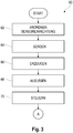
- FIGS Figures 3 and 4th One embodiment of a method 60 for securing a machine or system 14 arranged in a security area 12 is shown.
- the method 60 describes the function of the access security system 10 from FIGS Figures 1 and 2nd .
- a first step 62 of the method 60 the sensor device 16 is provided.
- a light pulse is sent from the optical transmitter 22 to the optical receiver 24.
- a sensor signal is generated by means of the sensor device 16 based on the reception of the light pulse by the receiver 24.
- the sensor signal is read out by means of the control device 18.
- step 70 of the method 60 the machine or system 14 arranged in the security area 12 is controlled by means of the control device 18 taking into account the sensor signal.
- the locking device 40 with the base body 42 and the blocking element 44 arranged thereon is provided.
- the blocking element 44 is arranged in the release position 48, in which the blocking element 44 is arranged outside a beam path 28 of the light pulse between the transmitter 22 and the receiver 24.
- the blocking element 44 is transferred from the release position 48 into the blocking position 50, in which the blocking element 44 is arranged in a beam path 28 of the light pulse between the transmitter 22 and the receiver 24 in order to receive the light pulse To block.
- the locking device 40 is locked in the locked position 50 by means of a securing element 46.
- a lockable securing element 46 is inserted into a receptacle of the locking device 40 in order to hold the blocking element 44 in its blocking position 50.
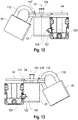
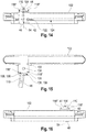
- FIGS Figures 5 to 16 A second embodiment of an access security system 100 is shown.
- the access security system 100 has essentially the same components as the access security system 10 from FIGS Figures 1 and 2nd on. The same components are therefore identified by the same reference symbols and are not explained in more detail.
- the Figures 5 and 7 to 11 show different views of the access security system 100 in a release state in which the blocking element 44 is arranged in the release position 48.
- the Figures 6 and 12 to 16 show different views of the access security system 100 in a locked state, in which the blocking element 44 is arranged in the locked position 50.
- the access security system 100 furthermore has a bar 102 in which one or more transmitters 22 or one or more receivers 24 are arranged.
- the bar 102 thus forms a housing for the transmitters 22 or the receivers 24.
- the bar 102 can be arranged on one side of the access 20.
- the access protection system 100 here has a coupling element 122 which rigidly connects the strip 102 and the base body 42 to one another.
- the strip 102 has a first groove 124, which extends in an extension direction of the strip 102.
- the direction of extension of the first groove is preferably perpendicular to the beam path 28 of the light pulse and the pivot axis 54.
- the base body 42 has a second groove which extends in the same direction of extension.
- the coupling element 122 also extends in the direction of extension and engages both in the first groove and in the second groove in order to rigidly connect the base body 42 and the strip 102 to one another.
- the base body 42 can also be fastened to the strip 102 by means of further fastening means, for example one or more screws.
- the blocking element 44 is in the embodiment of FIG Figures 5 to 16 as in embodiment (A) of Fig. 2 mounted on the base body 42 so as to be rotatable or pivotable about a pivot axis 54. Different from the embodiment (A) of the Fig. 2 The pivot axis 54 runs parallel to a beam path 28 of the light pulse of the sensor device 16.
- the access security system 100 also has a handle 104 in order to be able to pivot the blocking element 44 relative to the base body 42 by hand. Basically, a pivoting movement of the blocking element 44 driven by an actuator would also be conceivable. However, pivoting of the blocking element 44 by hand offers simple handling and also saves costs for actuators that are otherwise to be provided.
- the handle 104 shown preferably runs along or parallel to the pivot axis 54 about which the blocking element 44 can be pivoted.
- the blocking element can be coupled to the base body 42 via a spring element (not shown) arranged along the pivot axis 54.
- This spring element can exert a spring force which presses the blocking element 44 against the upper side of the base body 44. Additional spacers can be provided for stabilization.
- the locking device 40 can also have a receptacle for the securing element 46.
- the securing element 46 When the securing element 46 is inserted into the receptacle, the blocking element 44 is held in its locked position 50.
- the securing element 46 is designed as a padlock in the present embodiment.
- the securing element has a bracket 110 and is lockable, i.e. that the bracket 110 can be locked against a base body of the securing element.
- the blocking element 44 can furthermore have a bore 106 for the securing element 46.
- the bore 106 forms the receptacle of the locking device 40.
- the latter can additionally use the bracket 110 of the securing element Insert 46 into bore 106.
- a pivoting of the blocking element 44 out of its locked position 50 is then no longer possible.
- the securing element 46 would collide with the base body 42 of the locking device 48, so that the locking lever 52 is blocked in its locked position 50.
- the base body 42 can furthermore have a cutout 108, which is at least partially aligned with the bore 106 of the blocking element 44 in the blocking position 50 of the blocking element 44.
- the recess 108 of the base body 42 can also be designed as a bore.
- the bracket 110 of the securing element 46 can then be guided through the bore 106 and the recess 108 in order to connect the base body 42 and the blocking element 44 in a rotationally fixed manner about the axis of rotation 54 in order to lock the blocking element 44 in to hold the blocking position 50.
- the blocking element 44 has two bores 106 as receptacles for a lockable securing element 46 in each case.
- Two holes have the advantage that several (two) padlocks can be inserted into them. In this way, each operator can insert his personal padlock into one of the two holes.
- the base body 42 can also have two cutouts 108, which in the blocking position 50 of the blocking element 44 are at least partially aligned with the bores 106 provided in the blocking element 44.
- these cutouts 108 can also be configured as bores. They offer a further mechanical protection for this, which prevents the blocking element 44 from being pivotable out of its locked position 50 when the padlock is suspended. Since the cutouts 108 are preferably exactly aligned with the bores 106, a form fit between the bracket 110 of the padlock and the respective bore 106 or cutout 108 arises, so to speak, when a padlock is hooked into one of the two openings.
- the blocking element 44 can preferably be latched to the base body 42 both in the release position 48 and in the blocking position 50.
- the base body 42 has two recesses 112, 120 on its upper side, in which the blocking element 44 can be arranged flush. This creates a kind of positive connection between the blocking element 44 and the recesses 112 or 120.
- the first recess 112 is assigned to the release position 48.
- the second recess 120 is assigned to the blocking position 50. Both recesses 112, 120 are laterally delimited by two webs. These serve as lateral walls which prevent the blocking element 44 in the release position 48 or in the blocking position 50 from slipping or pivoting.
- the base body 42 has a first web 114 and a second web 116, which serve as side walls of the first recess 112.
- the second web 116 also has two lugs 118 ′, 118 ′′, which are designed as webs and serve as side walls of the second recess 120.
- the first and the second recess 112, 120 are preferably arranged at an angle of 90 ° to one another.
- the blocking element 44 In order to pivot the blocking element 44 from the release position 48 into the blocking position 50 or from the blocking position 50 into the release position 48, the blocking element 44 has to be moved upwards, that is to say away from the base body 42, along the pivot axis 54 over the webs 114, 116, 118 ', 118 ". The operator must overcome the spring force exerted by the spring element. Only then can the blocking element 44 be pivoted into the other position.
- FIG 17 A third embodiment of an access security system 100 'is shown.
- the access security system 100 ' is shown in the locked state in which the blocking element 44' is arranged in the locked position 50.
- the access protection system 100 ′ has essentially the same components as the access protection system 100 that is shown in FIGS Figures 5 to 16 is shown on. The same components are therefore identified by the same reference symbols and are not explained in more detail.
- the access protection system 100 differs from the access protection system 100 in that the pivot axis 54' of the locking device 40 'does not run parallel but perpendicular to a beam path 28 of the light pulse of the sensor device 16.
- the pivot axis 54 ' runs parallel to the direction of extension of the strip 102.
- the blocking element 44' is rotated or folded over about the pivot axis 54 'between the release position 48 and the blocking position 50.
- the base body 42 ' has a pin or rod 128 which is arranged along the pivot axis 54'.
- the blocking element 44 ' is rotatably mounted on the base body 42' by means of the pin or rod 128.
- the blocking element 44 'again has two bores 106' and the base body 42 'has corresponding cutouts 108' which are aligned with the bores 106 'in the blocking position 50.
- the bracket of a securing element 46 can be guided through the bores 106 'and the cutouts 108' in order to block the blocking element 44 'in the blocking position 50.
Landscapes
- Engineering & Computer Science (AREA)
- General Engineering & Computer Science (AREA)
- Mechanical Engineering (AREA)
- Life Sciences & Earth Sciences (AREA)
- Remote Sensing (AREA)
- Physics & Mathematics (AREA)
- Radar, Positioning & Navigation (AREA)
- General Life Sciences & Earth Sciences (AREA)
- General Physics & Mathematics (AREA)
- Geophysics (AREA)
- Burglar Alarm Systems (AREA)
- Switches Operated By Changes In Physical Conditions (AREA)
- Safety Devices In Control Systems (AREA)
Applications Claiming Priority (1)
| Application Number | Priority Date | Filing Date | Title |
|---|---|---|---|
| DE102019102004.2A DE102019102004B3 (de) | 2019-01-28 | 2019-01-28 | Verbessertes Zugangsabsicherungssystem zum Absichern einer Maschine oder Anlage |
Publications (2)
| Publication Number | Publication Date |
|---|---|
| EP3690302A1 true EP3690302A1 (fr) | 2020-08-05 |
| EP3690302B1 EP3690302B1 (fr) | 2022-05-04 |
Family
ID=69177014
Family Applications (1)
| Application Number | Title | Priority Date | Filing Date |
|---|---|---|---|
| EP20152330.5A Active EP3690302B1 (fr) | 2019-01-28 | 2020-01-17 | Système amélioré de sécurisation d'accès permettant de sécuriser une machine ou une installation |
Country Status (5)
| Country | Link |
|---|---|
| US (1) | US11280450B2 (fr) |
| EP (1) | EP3690302B1 (fr) |
| JP (1) | JP7539233B2 (fr) |
| CN (1) | CN111486332B (fr) |
| DE (1) | DE102019102004B3 (fr) |
Families Citing this family (2)
| Publication number | Priority date | Publication date | Assignee | Title |
|---|---|---|---|---|
| CN113819387B (zh) * | 2021-10-22 | 2023-06-23 | 深圳市意普兴科技有限公司 | 一种智能制造用光幕保护装置 |
| US20250301416A1 (en) * | 2024-03-22 | 2025-09-25 | Waterford Consultants, LLC | Methods for mitigating radio-frequency radiation exposure using power interrupters |
Citations (4)
| Publication number | Priority date | Publication date | Assignee | Title |
|---|---|---|---|---|
| DE4318518C1 (de) * | 1993-06-03 | 1994-09-01 | Fuss Fritz Gmbh & Co | Türüberwachungsvorrichtung |
| JP2000199599A (ja) * | 1999-01-08 | 2000-07-18 | Komatsu Ltd | プレス機械の防護ガ―ド |
| JP3929156B2 (ja) * | 1998-01-12 | 2007-06-13 | 株式会社小松製作所 | プレス機械の防護ガード |
| DE102012111433A1 (de) | 2012-11-26 | 2014-05-28 | Pilz Auslandsbeteiligungen Gmbh | Optoelektrische Schutzeinrichtung zum Absichern einer Gefahrenstelle |
Family Cites Families (35)
| Publication number | Priority date | Publication date | Assignee | Title |
|---|---|---|---|---|
| CA1093192A (fr) * | 1978-06-01 | 1981-01-06 | Canadian General Electric Company Limited | Dispositif de protection a cellules photoelectriques a infrarouge |
| DE3213491C1 (de) * | 1982-04-10 | 1983-07-21 | Adam Opel AG, 6090 Rüsselsheim | Sicherheitseinrichtung an beweglichen Schliessteilen,insbesondere an Schutzklappen von Bearbeitungsmaschinen |
| JPS62163102A (ja) * | 1986-01-14 | 1987-07-18 | Seiichi Ito | 制御回路 |
| JP2610542B2 (ja) * | 1990-07-16 | 1997-05-14 | 日本信号株式会社 | 作業の安全システム構成方法 |
| CN2258224Y (zh) * | 1995-12-28 | 1997-07-23 | 北京朗瑞尔装饰工程有限公司 | 上滑轨道门的光电传感器安全装置 |
| AUPN744696A0 (en) * | 1996-01-05 | 1996-02-01 | Appleyard, Thomas John | Safety apparatus and protection method for machines |
| DE19649593B4 (de) * | 1996-11-29 | 2004-08-26 | Leuze Electronic Gmbh + Co Kg | Verriegelungseinrichtung |
| US5950767A (en) * | 1997-08-15 | 1999-09-14 | Otis Elevator Company | Optical door lock |
| US6247664B1 (en) * | 1999-06-25 | 2001-06-19 | Siecor Operations, Llc | Reel monitor devices and methods of using the same |
| AU2007201914B2 (en) * | 1999-10-01 | 2011-07-21 | Sawstop Holding Llc | Safety systems for power equipment |
| AU2004231160B2 (en) * | 2001-11-29 | 2005-09-08 | Pemaco Pty Ltd | A material processing machine |
| JP2003218679A (ja) * | 2002-01-25 | 2003-07-31 | Keyence Corp | 多光軸光電式安全装置 |
| JP2004042101A (ja) | 2002-07-12 | 2004-02-12 | Toa Kogyo Kk | 安全装置 |
| US6733053B2 (en) * | 2002-09-27 | 2004-05-11 | Hodge Products, Inc. | Trash container locking apparatus and method |
| US6925785B1 (en) * | 2002-11-13 | 2005-08-09 | Jerry R. Kawasaki | Bear-resistant pannier |
| DE102004020995C5 (de) * | 2004-04-19 | 2016-12-08 | Pilz Gmbh & Co. Kg | Meldegerät für eine Sicherheitsschaltung |
| DE102005005906B4 (de) * | 2005-02-09 | 2008-02-21 | Sick Ag | Sensorsystem und Sicherungsverfahren |
| DE102006042562A1 (de) * | 2005-09-21 | 2007-05-16 | Brose Fahrzeugteile | Schutzvorrichtung als Einklemmschutz, insbesondere für ein Kraftfahrzeug |
| EP1956284B1 (fr) * | 2007-02-12 | 2012-12-19 | ThyssenKrupp System Engineering GmbH | Procédé et dispositif destinés à la sécurisation d'au moins une personne se trouvant dans une zone de danger |
| DE102007012976A1 (de) * | 2007-03-14 | 2008-09-18 | Fraba Ag | In Serie geschaltete optische Schaltleisten |
| DE102008060004B4 (de) * | 2008-11-25 | 2021-09-02 | Pilz Gmbh & Co. Kg | Sicherheitsschalter zum Erzeugen eines Anlagenfreigabesignals in Abhängigkeit von der Position einer beweglichen Schutztür |
| US20110049339A1 (en) * | 2009-09-01 | 2011-03-03 | Leeser Christian | Contact and non-contact entrapment protection system |
| DE202010000032U1 (de) * | 2010-01-13 | 2011-03-10 | Krones Ag | Verriegelungsvorrichtung und Sicherungseinrichtung für einen Arbeitsbereich einer Maschine |
| DE102010007388A1 (de) * | 2010-02-02 | 2011-08-04 | Pilz Auslandsbeteiligungen GmbH, 73760 | Verrieglungseinrichtung mit Zuhaltung für Schutztüren |
| US8466786B2 (en) * | 2010-08-16 | 2013-06-18 | Rav-Mafteah Ltd. | Locking mechanism with sabbath control unit |
| US8686869B2 (en) * | 2010-12-29 | 2014-04-01 | Secureall Corporation | Alignment-related operation and position sensing of electronic and other locks and other objects |
| EP3188082B1 (fr) * | 2012-02-22 | 2019-12-04 | Master Lock Company LLC | Systèmes et procédés de verrouillage de sécurité |
| DE102012111342A1 (de) * | 2012-11-23 | 2014-05-28 | Pilz Gmbh & Co. Kg | Schutztürüberwachungssystem |
| CN103591434B (zh) * | 2013-11-20 | 2016-05-11 | 天津大学 | 用于曲柄型压力机床的双重安全防护装置及方法 |
| DE102014114066A1 (de) * | 2014-09-29 | 2016-03-31 | Pilz Gmbh & Co. Kg | Kameraeinheit zum Überwachen eines Raumbereichs |
| DE202014105201U1 (de) | 2014-10-30 | 2014-11-11 | Robert Bosch Gmbh | Schalter und Sicherungssystem zur Überwachung eines zulässigen Arbeitsbetriebes einer Maschine oder einer Vorrichtung |
| PL3346177T3 (pl) * | 2017-01-04 | 2019-10-31 | Sick Ag | Urządzenie zabezpieczające |
| US10127792B1 (en) * | 2017-05-12 | 2018-11-13 | The Boeing Company | Safety system for operations having a working field on an opposite side of a barrier from a device |
| CN107570646B (zh) * | 2017-08-09 | 2019-08-06 | 宁波市镇海华隆紧固件有限公司 | 一种螺栓滚丝机防护装置 |
| AT521530B1 (de) * | 2018-07-27 | 2020-04-15 | Trumpf Maschinen Austria Gmbh & Co Kg | Biegepresse und Verfahren zum Betreiben einer Biegepresse |
-
2019
- 2019-01-28 DE DE102019102004.2A patent/DE102019102004B3/de active Active
-
2020
- 2020-01-17 EP EP20152330.5A patent/EP3690302B1/fr active Active
- 2020-01-22 JP JP2020008178A patent/JP7539233B2/ja active Active
- 2020-01-23 CN CN202010076955.0A patent/CN111486332B/zh active Active
- 2020-01-27 US US16/773,928 patent/US11280450B2/en not_active Expired - Fee Related
Patent Citations (4)
| Publication number | Priority date | Publication date | Assignee | Title |
|---|---|---|---|---|
| DE4318518C1 (de) * | 1993-06-03 | 1994-09-01 | Fuss Fritz Gmbh & Co | Türüberwachungsvorrichtung |
| JP3929156B2 (ja) * | 1998-01-12 | 2007-06-13 | 株式会社小松製作所 | プレス機械の防護ガード |
| JP2000199599A (ja) * | 1999-01-08 | 2000-07-18 | Komatsu Ltd | プレス機械の防護ガ―ド |
| DE102012111433A1 (de) | 2012-11-26 | 2014-05-28 | Pilz Auslandsbeteiligungen Gmbh | Optoelektrische Schutzeinrichtung zum Absichern einer Gefahrenstelle |
Also Published As
| Publication number | Publication date |
|---|---|
| EP3690302B1 (fr) | 2022-05-04 |
| JP2020129364A (ja) | 2020-08-27 |
| CN111486332A (zh) | 2020-08-04 |
| DE102019102004B3 (de) | 2020-06-10 |
| US20200263828A1 (en) | 2020-08-20 |
| CN111486332B (zh) | 2024-03-19 |
| US11280450B2 (en) | 2022-03-22 |
| JP7539233B2 (ja) | 2024-08-23 |
Similar Documents
| Publication | Publication Date | Title |
|---|---|---|
| EP2352948B1 (fr) | Commutateur de sécurité pour produire un signal de libération de l'installation en fonction de la position d'une porte de protection mobile | |
| EP2923140B1 (fr) | Système de surveillance de porte de protection | |
| EP3543439B1 (fr) | Procédé pour un ensemble serrure | |
| EP4080102B1 (fr) | Interrupteur de sécurité à gâchette | |
| EP3690302B1 (fr) | Système amélioré de sécurisation d'accès permettant de sécuriser une machine ou une installation | |
| WO2008110226A1 (fr) | Dispositif pour le maintien libérable d'un état fermé de manière verrouillée d'un dispositif de séparation de compartiment | |
| AT510969B1 (de) | Werkzeughalterung für abkantpresse | |
| DE10006427C2 (de) | Bewegungsanlage für Leistungsschaltvorrichtung | |
| EP1259340B1 (fr) | Dispositif de securite pour machine de production, par exemple une presse plieuse | |
| DE102008032246B4 (de) | Vorrichtung zum lösbaren Verriegeln eines geschlossenen Zustandes einer Raumtrenneinrichtung | |
| DE69928954T2 (de) | Türverriegelung | |
| DE10216594A1 (de) | Schaltschrank mit Einschubkassette | |
| DE10151862A1 (de) | Vorrichtung zur Betätigung eines Verschlusses von Türen oder Klappen, insbesondere an Fahrzeugen | |
| EP3128528A1 (fr) | Agencement de module | |
| EP2605257B1 (fr) | Entraînement par moteur pour un disjoncteur | |
| DE112011104984T5 (de) | Drehverriegelung | |
| DE102010035765B4 (de) | Vorrichtung zum Überwachen des Zustandes einer Schutzeinrichtung einer Maschine, insbesondere Sicherheitsschalter, und Verfahren zum Betrieb einer solchen Vorrichtung | |
| DE102007013479B4 (de) | Vorrichtung zum lösbaren Verriegeln eines geschlossenen Zustandes einer Raumtrenneinrichtung, insbesondere Sicherheitsschalter mit Drehrichtungsumkehr der Betätigungsrichtung | |
| EP0426957A2 (fr) | Système de verrouillage pour des coffres-forts ou des portes de sécurité ou semblable | |
| DE102016004835B4 (de) | Sicherheitsschalter | |
| EP1914609A1 (fr) | Interrupteur de sécurité comportant des moyens pour determiner sa position | |
| DE3720550A1 (de) | Mehrfachverriegelung | |
| DE29923398U1 (de) | Schließsystem für Möbel | |
| EP1321706A2 (fr) | Dispositif de protection sans contact | |
| DE102006047525A1 (de) | Arretiervorrichtung einer Längsverstellvorrichtung eines Kraftfahrzeugsitzes mit zwei Schienenpaaren |
Legal Events
| Date | Code | Title | Description |
|---|---|---|---|
| PUAI | Public reference made under article 153(3) epc to a published international application that has entered the european phase |
Free format text: ORIGINAL CODE: 0009012 |
|
| STAA | Information on the status of an ep patent application or granted ep patent |
Free format text: STATUS: THE APPLICATION HAS BEEN PUBLISHED |
|
| AK | Designated contracting states |
Kind code of ref document: A1 Designated state(s): AL AT BE BG CH CY CZ DE DK EE ES FI FR GB GR HR HU IE IS IT LI LT LU LV MC MK MT NL NO PL PT RO RS SE SI SK SM TR |
|
| AX | Request for extension of the european patent |
Extension state: BA ME |
|
| STAA | Information on the status of an ep patent application or granted ep patent |
Free format text: STATUS: REQUEST FOR EXAMINATION WAS MADE |
|
| 17P | Request for examination filed |
Effective date: 20210204 |
|
| RBV | Designated contracting states (corrected) |
Designated state(s): AL AT BE BG CH CY CZ DE DK EE ES FI FR GB GR HR HU IE IS IT LI LT LU LV MC MK MT NL NO PL PT RO RS SE SI SK SM TR |
|
| GRAP | Despatch of communication of intention to grant a patent |
Free format text: ORIGINAL CODE: EPIDOSNIGR1 |
|
| STAA | Information on the status of an ep patent application or granted ep patent |
Free format text: STATUS: GRANT OF PATENT IS INTENDED |
|
| INTG | Intention to grant announced |
Effective date: 20210709 |
|
| GRAJ | Information related to disapproval of communication of intention to grant by the applicant or resumption of examination proceedings by the epo deleted |
Free format text: ORIGINAL CODE: EPIDOSDIGR1 |
|
| STAA | Information on the status of an ep patent application or granted ep patent |
Free format text: STATUS: REQUEST FOR EXAMINATION WAS MADE |
|
| INTC | Intention to grant announced (deleted) | ||
| GRAP | Despatch of communication of intention to grant a patent |
Free format text: ORIGINAL CODE: EPIDOSNIGR1 |
|
| STAA | Information on the status of an ep patent application or granted ep patent |
Free format text: STATUS: GRANT OF PATENT IS INTENDED |
|
| INTG | Intention to grant announced |
Effective date: 20220127 |
|
| GRAS | Grant fee paid |
Free format text: ORIGINAL CODE: EPIDOSNIGR3 |
|
| GRAA | (expected) grant |
Free format text: ORIGINAL CODE: 0009210 |
|
| STAA | Information on the status of an ep patent application or granted ep patent |
Free format text: STATUS: THE PATENT HAS BEEN GRANTED |
|
| RBV | Designated contracting states (corrected) |
Designated state(s): AL AT BE BG CH CY CZ DK EE ES FI FR GB GR HR HU IE IS IT LI LT LU LV MC MK MT NL NO PL PT RO RS SE SI SK SM TR |
|
| REG | Reference to a national code |
Ref country code: DE Ref legal event code: R108 |
|
| AK | Designated contracting states |
Kind code of ref document: B1 Designated state(s): AL AT BE BG CH CY CZ DK EE ES FI FR GB GR HR HU IE IS IT LI LT LU LV MC MK MT NL NO PL PT RO RS SE SI SK SM TR |
|
| REG | Reference to a national code |
Ref country code: GB Ref legal event code: FG4D Free format text: NOT ENGLISH |
|
| REG | Reference to a national code |
Ref country code: CH Ref legal event code: EP |
|
| REG | Reference to a national code |
Ref country code: AT Ref legal event code: REF Ref document number: 1489395 Country of ref document: AT Kind code of ref document: T Effective date: 20220515 |
|
| REG | Reference to a national code |
Ref country code: IE Ref legal event code: FG4D Free format text: LANGUAGE OF EP DOCUMENT: GERMAN |
|
| REG | Reference to a national code |
Ref country code: LT Ref legal event code: MG9D |
|
| REG | Reference to a national code |
Ref country code: NL Ref legal event code: MP Effective date: 20220504 |
|
| PG25 | Lapsed in a contracting state [announced via postgrant information from national office to epo] |
Ref country code: SE Free format text: LAPSE BECAUSE OF FAILURE TO SUBMIT A TRANSLATION OF THE DESCRIPTION OR TO PAY THE FEE WITHIN THE PRESCRIBED TIME-LIMIT Effective date: 20220504 Ref country code: PT Free format text: LAPSE BECAUSE OF FAILURE TO SUBMIT A TRANSLATION OF THE DESCRIPTION OR TO PAY THE FEE WITHIN THE PRESCRIBED TIME-LIMIT Effective date: 20220905 Ref country code: NO Free format text: LAPSE BECAUSE OF FAILURE TO SUBMIT A TRANSLATION OF THE DESCRIPTION OR TO PAY THE FEE WITHIN THE PRESCRIBED TIME-LIMIT Effective date: 20220804 Ref country code: NL Free format text: LAPSE BECAUSE OF FAILURE TO SUBMIT A TRANSLATION OF THE DESCRIPTION OR TO PAY THE FEE WITHIN THE PRESCRIBED TIME-LIMIT Effective date: 20220504 Ref country code: LT Free format text: LAPSE BECAUSE OF FAILURE TO SUBMIT A TRANSLATION OF THE DESCRIPTION OR TO PAY THE FEE WITHIN THE PRESCRIBED TIME-LIMIT Effective date: 20220504 Ref country code: HR Free format text: LAPSE BECAUSE OF FAILURE TO SUBMIT A TRANSLATION OF THE DESCRIPTION OR TO PAY THE FEE WITHIN THE PRESCRIBED TIME-LIMIT Effective date: 20220504 Ref country code: GR Free format text: LAPSE BECAUSE OF FAILURE TO SUBMIT A TRANSLATION OF THE DESCRIPTION OR TO PAY THE FEE WITHIN THE PRESCRIBED TIME-LIMIT Effective date: 20220805 Ref country code: FI Free format text: LAPSE BECAUSE OF FAILURE TO SUBMIT A TRANSLATION OF THE DESCRIPTION OR TO PAY THE FEE WITHIN THE PRESCRIBED TIME-LIMIT Effective date: 20220504 Ref country code: ES Free format text: LAPSE BECAUSE OF FAILURE TO SUBMIT A TRANSLATION OF THE DESCRIPTION OR TO PAY THE FEE WITHIN THE PRESCRIBED TIME-LIMIT Effective date: 20220504 Ref country code: BG Free format text: LAPSE BECAUSE OF FAILURE TO SUBMIT A TRANSLATION OF THE DESCRIPTION OR TO PAY THE FEE WITHIN THE PRESCRIBED TIME-LIMIT Effective date: 20220804 |
|
| PG25 | Lapsed in a contracting state [announced via postgrant information from national office to epo] |
Ref country code: RS Free format text: LAPSE BECAUSE OF FAILURE TO SUBMIT A TRANSLATION OF THE DESCRIPTION OR TO PAY THE FEE WITHIN THE PRESCRIBED TIME-LIMIT Effective date: 20220504 Ref country code: PL Free format text: LAPSE BECAUSE OF FAILURE TO SUBMIT A TRANSLATION OF THE DESCRIPTION OR TO PAY THE FEE WITHIN THE PRESCRIBED TIME-LIMIT Effective date: 20220504 Ref country code: LV Free format text: LAPSE BECAUSE OF FAILURE TO SUBMIT A TRANSLATION OF THE DESCRIPTION OR TO PAY THE FEE WITHIN THE PRESCRIBED TIME-LIMIT Effective date: 20220504 Ref country code: IS Free format text: LAPSE BECAUSE OF FAILURE TO SUBMIT A TRANSLATION OF THE DESCRIPTION OR TO PAY THE FEE WITHIN THE PRESCRIBED TIME-LIMIT Effective date: 20220904 |
|
| PG25 | Lapsed in a contracting state [announced via postgrant information from national office to epo] |
Ref country code: SM Free format text: LAPSE BECAUSE OF FAILURE TO SUBMIT A TRANSLATION OF THE DESCRIPTION OR TO PAY THE FEE WITHIN THE PRESCRIBED TIME-LIMIT Effective date: 20220504 Ref country code: SK Free format text: LAPSE BECAUSE OF FAILURE TO SUBMIT A TRANSLATION OF THE DESCRIPTION OR TO PAY THE FEE WITHIN THE PRESCRIBED TIME-LIMIT Effective date: 20220504 Ref country code: RO Free format text: LAPSE BECAUSE OF FAILURE TO SUBMIT A TRANSLATION OF THE DESCRIPTION OR TO PAY THE FEE WITHIN THE PRESCRIBED TIME-LIMIT Effective date: 20220504 Ref country code: EE Free format text: LAPSE BECAUSE OF FAILURE TO SUBMIT A TRANSLATION OF THE DESCRIPTION OR TO PAY THE FEE WITHIN THE PRESCRIBED TIME-LIMIT Effective date: 20220504 Ref country code: DK Free format text: LAPSE BECAUSE OF FAILURE TO SUBMIT A TRANSLATION OF THE DESCRIPTION OR TO PAY THE FEE WITHIN THE PRESCRIBED TIME-LIMIT Effective date: 20220504 Ref country code: CZ Free format text: LAPSE BECAUSE OF FAILURE TO SUBMIT A TRANSLATION OF THE DESCRIPTION OR TO PAY THE FEE WITHIN THE PRESCRIBED TIME-LIMIT Effective date: 20220504 |
|
| PLBE | No opposition filed within time limit |
Free format text: ORIGINAL CODE: 0009261 |
|
| STAA | Information on the status of an ep patent application or granted ep patent |
Free format text: STATUS: NO OPPOSITION FILED WITHIN TIME LIMIT |
|
| PG25 | Lapsed in a contracting state [announced via postgrant information from national office to epo] |
Ref country code: AL Free format text: LAPSE BECAUSE OF FAILURE TO SUBMIT A TRANSLATION OF THE DESCRIPTION OR TO PAY THE FEE WITHIN THE PRESCRIBED TIME-LIMIT Effective date: 20220504 |
|
| 26N | No opposition filed |
Effective date: 20230207 |
|
| PG25 | Lapsed in a contracting state [announced via postgrant information from national office to epo] |
Ref country code: SI Free format text: LAPSE BECAUSE OF FAILURE TO SUBMIT A TRANSLATION OF THE DESCRIPTION OR TO PAY THE FEE WITHIN THE PRESCRIBED TIME-LIMIT Effective date: 20220504 |
|
| PG25 | Lapsed in a contracting state [announced via postgrant information from national office to epo] |
Ref country code: LU Free format text: LAPSE BECAUSE OF NON-PAYMENT OF DUE FEES Effective date: 20230117 |
|
| REG | Reference to a national code |
Ref country code: BE Ref legal event code: MM Effective date: 20230131 |
|
| PG25 | Lapsed in a contracting state [announced via postgrant information from national office to epo] |
Ref country code: BE Free format text: LAPSE BECAUSE OF NON-PAYMENT OF DUE FEES Effective date: 20230131 |
|
| PG25 | Lapsed in a contracting state [announced via postgrant information from national office to epo] |
Ref country code: IE Free format text: LAPSE BECAUSE OF NON-PAYMENT OF DUE FEES Effective date: 20230117 |
|
| PG25 | Lapsed in a contracting state [announced via postgrant information from national office to epo] |
Ref country code: MC Free format text: LAPSE BECAUSE OF FAILURE TO SUBMIT A TRANSLATION OF THE DESCRIPTION OR TO PAY THE FEE WITHIN THE PRESCRIBED TIME-LIMIT Effective date: 20220504 |
|
| PG25 | Lapsed in a contracting state [announced via postgrant information from national office to epo] |
Ref country code: MC Free format text: LAPSE BECAUSE OF FAILURE TO SUBMIT A TRANSLATION OF THE DESCRIPTION OR TO PAY THE FEE WITHIN THE PRESCRIBED TIME-LIMIT Effective date: 20220504 |
|
| PG25 | Lapsed in a contracting state [announced via postgrant information from national office to epo] |
Ref country code: BG Free format text: LAPSE BECAUSE OF FAILURE TO SUBMIT A TRANSLATION OF THE DESCRIPTION OR TO PAY THE FEE WITHIN THE PRESCRIBED TIME-LIMIT Effective date: 20220504 |
|
| PG25 | Lapsed in a contracting state [announced via postgrant information from national office to epo] |
Ref country code: BG Free format text: LAPSE BECAUSE OF FAILURE TO SUBMIT A TRANSLATION OF THE DESCRIPTION OR TO PAY THE FEE WITHIN THE PRESCRIBED TIME-LIMIT Effective date: 20220504 |
|
| PGFP | Annual fee paid to national office [announced via postgrant information from national office to epo] |
Ref country code: CH Payment date: 20250201 Year of fee payment: 6 Ref country code: AT Payment date: 20250122 Year of fee payment: 6 |
|
| PGFP | Annual fee paid to national office [announced via postgrant information from national office to epo] |
Ref country code: FR Payment date: 20250127 Year of fee payment: 6 |
|
| PGFP | Annual fee paid to national office [announced via postgrant information from national office to epo] |
Ref country code: IT Payment date: 20250129 Year of fee payment: 6 Ref country code: GB Payment date: 20250128 Year of fee payment: 6 |
|
| PG25 | Lapsed in a contracting state [announced via postgrant information from national office to epo] |
Ref country code: CY Free format text: LAPSE BECAUSE OF FAILURE TO SUBMIT A TRANSLATION OF THE DESCRIPTION OR TO PAY THE FEE WITHIN THE PRESCRIBED TIME-LIMIT; INVALID AB INITIO Effective date: 20200117 |
|
| PG25 | Lapsed in a contracting state [announced via postgrant information from national office to epo] |
Ref country code: HU Free format text: LAPSE BECAUSE OF FAILURE TO SUBMIT A TRANSLATION OF THE DESCRIPTION OR TO PAY THE FEE WITHIN THE PRESCRIBED TIME-LIMIT; INVALID AB INITIO Effective date: 20200117 |
|
| PG25 | Lapsed in a contracting state [announced via postgrant information from national office to epo] |
Ref country code: TR Free format text: LAPSE BECAUSE OF FAILURE TO SUBMIT A TRANSLATION OF THE DESCRIPTION OR TO PAY THE FEE WITHIN THE PRESCRIBED TIME-LIMIT Effective date: 20220504 |