EP3690308A1 - Système de montage pour un luminaire et système de luminaire - Google Patents
Système de montage pour un luminaire et système de luminaire Download PDFInfo
- Publication number
- EP3690308A1 EP3690308A1 EP19382069.3A EP19382069A EP3690308A1 EP 3690308 A1 EP3690308 A1 EP 3690308A1 EP 19382069 A EP19382069 A EP 19382069A EP 3690308 A1 EP3690308 A1 EP 3690308A1
- Authority
- EP
- European Patent Office
- Prior art keywords
- bar
- mounting system
- hollow part
- self
- luminaire
- Prior art date
- Legal status (The legal status is an assumption and is not a legal conclusion. Google has not performed a legal analysis and makes no representation as to the accuracy of the status listed.)
- Withdrawn
Links
- 238000006073 displacement reaction Methods 0.000 claims abstract description 31
- 238000003780 insertion Methods 0.000 claims abstract description 26
- 230000037431 insertion Effects 0.000 claims abstract description 26
- 238000000605 extraction Methods 0.000 claims description 8
- 230000000295 complement effect Effects 0.000 claims description 4
- 230000007246 mechanism Effects 0.000 claims description 2
- 230000008878 coupling Effects 0.000 description 4
- 238000010168 coupling process Methods 0.000 description 4
- 238000005859 coupling reaction Methods 0.000 description 4
- 238000000034 method Methods 0.000 description 4
- 230000008569 process Effects 0.000 description 4
- 230000000903 blocking effect Effects 0.000 description 2
- 229910000831 Steel Inorganic materials 0.000 description 1
- 230000009471 action Effects 0.000 description 1
- 230000000712 assembly Effects 0.000 description 1
- 238000000429 assembly Methods 0.000 description 1
- 230000005484 gravity Effects 0.000 description 1
- 238000009434 installation Methods 0.000 description 1
- 238000012986 modification Methods 0.000 description 1
- 230000004048 modification Effects 0.000 description 1
- 239000010959 steel Substances 0.000 description 1
Images



Classifications
-
- F—MECHANICAL ENGINEERING; LIGHTING; HEATING; WEAPONS; BLASTING
- F21—LIGHTING
- F21V—FUNCTIONAL FEATURES OR DETAILS OF LIGHTING DEVICES OR SYSTEMS THEREOF; STRUCTURAL COMBINATIONS OF LIGHTING DEVICES WITH OTHER ARTICLES, NOT OTHERWISE PROVIDED FOR
- F21V21/00—Supporting, suspending, or attaching arrangements for lighting devices; Hand grips
- F21V21/10—Pendants, arms, or standards; Fixing lighting devices to pendants, arms, or standards
- F21V21/104—Pendants
-
- F—MECHANICAL ENGINEERING; LIGHTING; HEATING; WEAPONS; BLASTING
- F21—LIGHTING
- F21S—NON-PORTABLE LIGHTING DEVICES; SYSTEMS THEREOF; VEHICLE LIGHTING DEVICES SPECIALLY ADAPTED FOR VEHICLE EXTERIORS
- F21S8/00—Lighting devices intended for fixed installation
- F21S8/04—Lighting devices intended for fixed installation intended only for mounting on a ceiling or the like overhead structures
- F21S8/06—Lighting devices intended for fixed installation intended only for mounting on a ceiling or the like overhead structures by suspension
- F21S8/063—Lighting devices intended for fixed installation intended only for mounting on a ceiling or the like overhead structures by suspension with a rigid pendant, i.e. a pipe or rod
-
- F—MECHANICAL ENGINEERING; LIGHTING; HEATING; WEAPONS; BLASTING
- F21—LIGHTING
- F21V—FUNCTIONAL FEATURES OR DETAILS OF LIGHTING DEVICES OR SYSTEMS THEREOF; STRUCTURAL COMBINATIONS OF LIGHTING DEVICES WITH OTHER ARTICLES, NOT OTHERWISE PROVIDED FOR
- F21V21/00—Supporting, suspending, or attaching arrangements for lighting devices; Hand grips
- F21V21/02—Wall, ceiling, or floor bases; Fixing pendants or arms to the bases
- F21V21/03—Ceiling bases, e.g. ceiling roses
Definitions
- the present invention relates, in a first aspect, to a mounting system for a luminaire, particularly to hang a luminaire therefrom, which comprises components configured and arranged to provide an easy and quick installation of the system, and robust holding of the luminaire.
- a second aspect of the present invention relates to a luminaire system, comprising the mounting system of the first aspect of the present invention and a luminaire to be attached thereto.
- each bar must have an end configuration to fit into a through opening of a part fixed to a ceiling.
- end configuration is a threaded outer surface for the screwing therein of a nut, so the mounting process comprises first inserting the bar end with the outer threaded surface into such a through opening, and then screw that nut thereon, which makes the mounting process complicated and slow, as the operator must access with his hands to a very small space to introduce the nut and then couple the same to the threaded outer surface of the bar end.
- the present invention relates, in an aspect, to a mounting system for a luminaire, comprising:
- the mounting system comprises several hanger assemblies and bars like the ones described above (and below, in more detail).
- the bar can be cut at the desired length before the cut end, i.e. the second end, is to be inserted into the hollow part open bottom and locked by the self-locking member.
- said insertion displacement is a linear displacement along the longitudinal axis of the hollow part, although other types of insertion displacements are also covered by the present invention, for other embodiments.
- the at least one self-locking member is at least one-locking washer, to be traversed by and lock said second end of said bar.
- the at least one self-locking washer is an internal tooth self-locking washer with teeth extending at least radially inwards so that theirfree ends define a central through opening enlargeable by the second end of the bar when, in an insertion displacement of the bar, the second end of the bar exerts force against said teeth free ends until a portion of the second end of the bar traverses the enlarged through opening and is blocked, for a bar extraction displacement opposite to said insertion displacement, by friction of an outer surface (such as cylindrical or prismatic) of the second end with said teeth.
- the teeth of the self-locking washer generally, extend also axially with respect to the centre geometric axis of the self-locking washer, so that, in use (i.e., when the components of the mounting system are mounted), the teeth are tilted upwardly (when the mounting system is installed in a ceiling).
- the bar forces the central opening of the self-locking washer to enlarge by pushing them in the direction of the insertion displacement. That happens because that pushing causes the angle of the above mentioned tilt to increase, until the bar is completely inserted or considered as inserted enough so as the extraction displacement is blocked, specifically by friction of the teeth free ends with the outer surface of the bar.
- the at least one self-locking member comprises a ratchet mechanism configured and arranged so that the insertion displacement of the bar is allowed but a bar extraction displacement, opposite to that insertion displacement, is blocked.
- the inclusion in the mounting system of the first aspect of the present invention of different self-locking members known in the art is also embraced by the present invention.
- the outer surface of the second end of the bar and the self-blocking member has a kinetic friction coefficient ranging between and 0.1 ⁇ k and 0.8 ⁇ k , more preferably between 0.4 ⁇ k and 0.6 ⁇ k .
- bars with an outer surface of its second end having a different kinetic friction can also be included in the mounting system of the first aspect of the present invention.
- the hanger assembly comprises a fixing part configured to be fixed to said ceiling or wall, and wherein the above mentioned hollow part is to be fixed to said ceiling or wall indirectly by being configured to be coupled to that fixing part.
- the above mentioned hollow part is a first hollow part
- the fixing part is a second hollow part, wherein the first and second hollow parts are dimensioned so as one can be inserted into the other.
- the above mentioned hollow part, or each of the first and second hollow parts is a tubular hollow part.
- the inner shape of said tubular hollow part matches the shape of the bar (such as cylindrical or any type of prismatic shape: triangular, square, hexagonal, etc.) or at least provides an interior volume dimensioned to allow the insertion of the second end of the bar therein.
- first and second hollow parts are first and second tubular hollow parts
- outer and inner surfaces of, respectively, the first and second tubular hollow parts, or vice versa have complementary threads to be coupled to each other when one of the first and second tubular hollow parts is inserted into the other.
- Coupling means known in the art for the coupling of two tubular hollow parts when one is inserted into the other, and that tare different to those constituted by the complementary threads are also embraced by the present invention, for alternative embodiments.
- the outer diameter of the at least one self-locking washer is larger than the inner diameter or inner cross-dimension of the first or second tubular hollow part and larger than the inner diameter or inner cross-dimension of a through hole, for the insertion of the bar, defined by a wall of the other of the first and second tubular hollow parts, so that the at least one self-locking washer is trapped between a free perimeter edge of the first or second tubular hollow part and said wall.
- the self-locking washer (or a different type of self-locking member) is blocked into the first or second tubular hollow part in a different manner to the one described above, such as by means of friction of its outer perimeter with the inner contour of the corresponding tubular hollow part, or by means of some blocking configuration attached to or integral with the corresponding tubular hollow part (constituted, for example, by protuberant elements projecting inwardly from the inner contour of the corresponding tubular hollow part), or stuck or welded to that inner contour.
- Any means for blocking the self-locking washer into the corresponding tubular hollow part known for the skilled person are embraced by the present invention.
- the self-locking washer (or a different type of self-locking member) is integral with the corresponding tubular hollow part, i.e. defined thereby, projecting inwardly from the inner contour of that tubular hollow part.
- the above mentioned wall is a bottom wall of the first tubular hollow part, wherein the through hole defined by the wall provides the above mentioned open bottom of the hollow part.
- the through hole defined by the bottom wall of the first tubular hollow part has a larger diameter or cross-dimension than the outer diameter or outer cross-dimension of the bar, so a gap is defined between the bar and the contour of the through hole to allow the bar to tilt an angle ⁇ , the self-locking member being configured and arranged to allow said bar tilt.
- the bar By tilting the bar that angle ⁇ , or an angular portion thereof (the angular portion needed to compensate the non-horizontality of the ceiling), the bar is forced, by the action of gravity on the luminaire attached thereto, to be in a vertical position, so that the orientation of the luminaire is not affected by that non-horizontality of the ceiling.
- a second aspect of the present invention relates to a luminaire system, comprising the mounting system of the first aspect of the present invention and a luminaire comprising the above mentioned attachment point for the attaching of the first end of the bar thereto.
- the luminaire of the second aspect of the present invention is a suspension-type luminaire to be suspended from a ceiling when the hanger assembly of the mounting system is fixed to said ceiling.
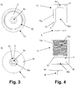
- the mounting system for a luminaire of the first aspect of the present invention comprises, as shown in Figures 1, 2 , 4 and 7 :
- outer and inner surfaces of, respectively, the first T1 and second T2 tubular hollow parts have complementary threads T1s, T2s to be coupled to each other when one of the first T1 and second T2 tubular hollow parts is inserted into the other.
- the first tubular hollow part T1 has a bottom wall W that defines a through hole Wo providing the above mentioned open bottom for the insertion of the bar B.
- the self-locking washer L is an internal tooth self-locking washer with teeth Lt extending radially inwards so that their free ends define a central through opening Lo enlargeable by the second end B2 of the bar B when, in an insertion displacement of the bar B, the second end B2 of the bar B exerts force against said teeth free ends until a portion of the second end B2 of the bar B traverses the enlarged through opening Lo and is blocked (situation illustrated in Figure 7 , right view), for a bar extraction displacement opposite to the insertion displacement, by friction of an outer surface of the second end B2 with the teeth Lt.
- the teeth Lt extend also axially with respect to the centre geometric axis of the self-locking washer L, so that, in use (i.e., when the components of the mounting system are mounted), the teeth Lt are tilted upwardly (when the mounting system is installed in a ceiling).
- the bar B enlarges the central opening Lo by pushing the teeth Lt in the direction of the insertion displacement. That happens because that pushing causes the angle ⁇ (see Figure 6 ) to increase, until the bar B is completely inserted or considered as inserted enough (as shown in Figure 7 ) so as the extraction displacement is blocked, specifically by friction of the teeth free ends with the outer surface of the bar B.
- the outer diameter of the self-locking washer L is larger than the inner diameter or inner cross-dimension of the second tubular hollow part T2 and larger than the diameter or cross-dimension of the through hole Wo of the bottom wall W of the first tubular hollow part T1, for the insertion of the bar B, so that the self-locking washer L is trapped between a free perimeter edge P of the second tubular hollow part T2 and the bottom wall W of the first tubular part T1, as shown in Figure 7 .
- the self-locking washer L is placed in a small housing H (see Figure 4 ) and, as stated above, trapped between edge P and an upper face of wall W that defines the bottom of said housing H. That's done, for the illustrated embodiment, when coupling both tubular hollow parts, T1, T2, by screwing, the coupling course arrives at an end point at which stepped lower perimeter edge S1 of T2 bumps against stepped perimeter surface S2 of T1 (see Figure 4 ).
- the second tubular hollow part T2 has a top wall V that defines a central through opening Vo so as to allow its attachment to a ceiling C (or wall) by passing therethrough a screw F1 which is screwed to an anchor plug F2 inserted into a through hole Co defined in the ceiling C.
- the mounting process is very simple and quick, as the operator only has to attach the second tubular hollow part T2 to the ceiling C, as explained above, and illustrated in Figure 7 left view, the couple by screwing the first tubular hollow part T1 to the second one T2, and then just insert the bar B through the hole Wo and the hole Lo, enlarging the latter until the second bar end B2 is well inserted in the inner chamber T2o defined within T2. At that point, as illustrated in Figure 7 right view, the extraction displacement of the bar B is locked by the self-locking washer.
- the operator can attach the first bar end B1 to the attachment point of the luminaire.
- hole Wo has a larger diameter or cross-dimension than the outer diameter or outer cross-dimension of the bar B, so a gap g is defined between the bar B and the contour of the through hole Wo to allow the bar B to tilt an angle ⁇ (see Figure 8 ), the self-locking member L being configured and arranged to allow said bar tilt.
- This feature has the purpose, already explained in a previous section, of compensating a possible non-horizontality of the ceiling, so that the bar B keeps its verticality, and the luminaire is suspended with the correct orientation.
- FIG. 9 the luminaire system of the second aspect of the present invention is shown, comprising the mounting system attached to a ceiling C, and a luminaire (particularly a suspension-type luminaire) attached to the first end B1 of the bar B.
Landscapes
- Engineering & Computer Science (AREA)
- General Engineering & Computer Science (AREA)
- Mutual Connection Of Rods And Tubes (AREA)
Priority Applications (1)
| Application Number | Priority Date | Filing Date | Title |
|---|---|---|---|
| EP19382069.3A EP3690308A1 (fr) | 2019-01-31 | 2019-01-31 | Système de montage pour un luminaire et système de luminaire |
Applications Claiming Priority (1)
| Application Number | Priority Date | Filing Date | Title |
|---|---|---|---|
| EP19382069.3A EP3690308A1 (fr) | 2019-01-31 | 2019-01-31 | Système de montage pour un luminaire et système de luminaire |
Publications (1)
| Publication Number | Publication Date |
|---|---|
| EP3690308A1 true EP3690308A1 (fr) | 2020-08-05 |
Family
ID=65529603
Family Applications (1)
| Application Number | Title | Priority Date | Filing Date |
|---|---|---|---|
| EP19382069.3A Withdrawn EP3690308A1 (fr) | 2019-01-31 | 2019-01-31 | Système de montage pour un luminaire et système de luminaire |
Country Status (1)
| Country | Link |
|---|---|
| EP (1) | EP3690308A1 (fr) |
Citations (7)
| Publication number | Priority date | Publication date | Assignee | Title |
|---|---|---|---|---|
| US2798748A (en) * | 1952-02-20 | 1957-07-09 | Maurer Albrecht | Annular clamping disc |
| US4691889A (en) * | 1985-12-20 | 1987-09-08 | Richards Peter S | Joint construction and overhead hanger |
| US20040141328A1 (en) * | 2003-01-17 | 2004-07-22 | Stone John D | Lighting fixtures having releasably attachable objects and methods for trimming lighting fixtures |
| US20150176761A1 (en) * | 2013-04-15 | 2015-06-25 | Michael C. Lenherr | Hanger System for Suspendible Illuminated Fixtures |
| CN103185318B (zh) * | 2011-12-28 | 2016-04-20 | 海洋王照明科技股份有限公司 | 灯具吊挂装置及使用该装置的吊挂灯具 |
| US20180142870A1 (en) * | 2016-11-21 | 2018-05-24 | Flex Ltd. | Push-on mechanical fastener for lighting fixture |
| CN108167719A (zh) * | 2018-01-31 | 2018-06-15 | 湖南金凤凰建材家居集成科技有限公司 | 一种吊灯的安装结构 |
-
2019
- 2019-01-31 EP EP19382069.3A patent/EP3690308A1/fr not_active Withdrawn
Patent Citations (7)
| Publication number | Priority date | Publication date | Assignee | Title |
|---|---|---|---|---|
| US2798748A (en) * | 1952-02-20 | 1957-07-09 | Maurer Albrecht | Annular clamping disc |
| US4691889A (en) * | 1985-12-20 | 1987-09-08 | Richards Peter S | Joint construction and overhead hanger |
| US20040141328A1 (en) * | 2003-01-17 | 2004-07-22 | Stone John D | Lighting fixtures having releasably attachable objects and methods for trimming lighting fixtures |
| CN103185318B (zh) * | 2011-12-28 | 2016-04-20 | 海洋王照明科技股份有限公司 | 灯具吊挂装置及使用该装置的吊挂灯具 |
| US20150176761A1 (en) * | 2013-04-15 | 2015-06-25 | Michael C. Lenherr | Hanger System for Suspendible Illuminated Fixtures |
| US20180142870A1 (en) * | 2016-11-21 | 2018-05-24 | Flex Ltd. | Push-on mechanical fastener for lighting fixture |
| CN108167719A (zh) * | 2018-01-31 | 2018-06-15 | 湖南金凤凰建材家居集成科技有限公司 | 一种吊灯的安装结构 |
Similar Documents
| Publication | Publication Date | Title |
|---|---|---|
| US5282600A (en) | Universal quick connect hanger for suspending a lighting system | |
| US8474774B2 (en) | Panel component holder | |
| US7080813B1 (en) | Assembly for suspending an object from a sloped surface | |
| US7462008B2 (en) | Structural fasteners and components thereof | |
| US6799982B2 (en) | Quick connect device for electrical fixture | |
| US4387417A (en) | Lamp retaining means within luminaire | |
| US20090074537A1 (en) | Structural fasteners and components thereof | |
| WO2021089365A1 (fr) | Système de raccordement pour luminaire et système d'éclairage utilisant le système de raccordement | |
| WO1993020313A1 (fr) | Element de fixation conçu pour fixer un objet tel qu'un filet, un fil metallique, un cable ou un element similaire a un support tel qu'un poteau | |
| EP3649302A1 (fr) | Ensemble ancre | |
| EP2086080B1 (fr) | Ensemble de suspension plafonnier | |
| US20240301971A1 (en) | Improvements in and relating to couplings | |
| US4947607A (en) | Suspended ceiling construction and compression strut therefor | |
| EP3690308A1 (fr) | Système de montage pour un luminaire et système de luminaire | |
| JP6321721B2 (ja) | 機器を取付ける取付装置及び取付装置の取付け方法 | |
| US5558455A (en) | Break-away banner rod fitter | |
| UA120872C2 (uk) | Пружинний тримач | |
| US2914661A (en) | Luminaire | |
| US20190257111A1 (en) | Locking device | |
| US20220412484A1 (en) | Cable or pipe supports | |
| EP4123853A1 (fr) | Structure de support pour profilés supportant des systèmes de transport de câbles dans des conduits industriels | |
| PT751327E (pt) | Elemento de fixacao para montagem de objectos alongados numa parede | |
| US11971155B2 (en) | Mounting bracket for affixing light fixtures to pilings | |
| US12146332B1 (en) | Base for utility pole | |
| EP4509728A1 (fr) | Ancre |
Legal Events
| Date | Code | Title | Description |
|---|---|---|---|
| PUAI | Public reference made under article 153(3) epc to a published international application that has entered the european phase |
Free format text: ORIGINAL CODE: 0009012 |
|
| STAA | Information on the status of an ep patent application or granted ep patent |
Free format text: STATUS: THE APPLICATION HAS BEEN PUBLISHED |
|
| AK | Designated contracting states |
Kind code of ref document: A1 Designated state(s): AL AT BE BG CH CY CZ DE DK EE ES FI FR GB GR HR HU IE IS IT LI LT LU LV MC MK MT NL NO PL PT RO RS SE SI SK SM TR |
|
| AX | Request for extension of the european patent |
Extension state: BA ME |
|
| STAA | Information on the status of an ep patent application or granted ep patent |
Free format text: STATUS: THE APPLICATION IS DEEMED TO BE WITHDRAWN |
|
| 18D | Application deemed to be withdrawn |
Effective date: 20210206 |