EP3690478A1 - Radarvorrichtung - Google Patents
Radarvorrichtung Download PDFInfo
- Publication number
- EP3690478A1 EP3690478A1 EP18862930.7A EP18862930A EP3690478A1 EP 3690478 A1 EP3690478 A1 EP 3690478A1 EP 18862930 A EP18862930 A EP 18862930A EP 3690478 A1 EP3690478 A1 EP 3690478A1
- Authority
- EP
- European Patent Office
- Prior art keywords
- antenna
- frequency
- detected point
- signal
- radar apparatus
- Prior art date
- Legal status (The legal status is an assumption and is not a legal conclusion. Google has not performed a legal analysis and makes no representation as to the accuracy of the status listed.)
- Withdrawn
Links
- 230000005540 biological transmission Effects 0.000 claims abstract description 21
- 230000005855 radiation Effects 0.000 claims description 37
- 238000001514 detection method Methods 0.000 abstract description 8
- 230000015572 biosynthetic process Effects 0.000 abstract 1
- 230000000116 mitigating effect Effects 0.000 abstract 1
- 238000000034 method Methods 0.000 description 33
- 238000010586 diagram Methods 0.000 description 24
- 238000001914 filtration Methods 0.000 description 7
- 238000005070 sampling Methods 0.000 description 4
- 238000005259 measurement Methods 0.000 description 3
- 238000005516 engineering process Methods 0.000 description 2
- 230000003044 adaptive effect Effects 0.000 description 1
- 230000007423 decrease Effects 0.000 description 1
- 230000000694 effects Effects 0.000 description 1
- 239000002184 metal Substances 0.000 description 1
- 230000002093 peripheral effect Effects 0.000 description 1
- 230000035945 sensitivity Effects 0.000 description 1
- 230000001629 suppression Effects 0.000 description 1
Images







Classifications
-
- G—PHYSICS
- G01—MEASURING; TESTING
- G01S—RADIO DIRECTION-FINDING; RADIO NAVIGATION; DETERMINING DISTANCE OR VELOCITY BY USE OF RADIO WAVES; LOCATING OR PRESENCE-DETECTING BY USE OF THE REFLECTION OR RERADIATION OF RADIO WAVES; ANALOGOUS ARRANGEMENTS USING OTHER WAVES
- G01S7/00—Details of systems according to groups G01S13/00, G01S15/00, G01S17/00
- G01S7/02—Details of systems according to groups G01S13/00, G01S15/00, G01S17/00 of systems according to group G01S13/00
- G01S7/023—Interference mitigation, e.g. reducing or avoiding non-intentional interference with other HF-transmitters, base station transmitters for mobile communication or other radar systems, e.g. using electro-magnetic interference [EMI] reduction techniques
- G01S7/0232—Avoidance by frequency multiplex
-
- G—PHYSICS
- G01—MEASURING; TESTING
- G01S—RADIO DIRECTION-FINDING; RADIO NAVIGATION; DETERMINING DISTANCE OR VELOCITY BY USE OF RADIO WAVES; LOCATING OR PRESENCE-DETECTING BY USE OF THE REFLECTION OR RERADIATION OF RADIO WAVES; ANALOGOUS ARRANGEMENTS USING OTHER WAVES
- G01S13/00—Systems using the reflection or reradiation of radio waves, e.g. radar systems; Analogous systems using reflection or reradiation of waves whose nature or wavelength is irrelevant or unspecified
- G01S13/02—Systems using reflection of radio waves, e.g. primary radar systems; Analogous systems
- G01S13/06—Systems determining position data of a target
- G01S13/08—Systems for measuring distance only
- G01S13/32—Systems for measuring distance only using transmission of continuous waves, whether amplitude-, frequency-, or phase-modulated, or unmodulated
- G01S13/34—Systems for measuring distance only using transmission of continuous waves, whether amplitude-, frequency-, or phase-modulated, or unmodulated using transmission of continuous, frequency-modulated waves while heterodyning the received signal, or a signal derived therefrom, with a locally-generated signal related to the contemporaneously transmitted signal
- G01S13/343—Systems for measuring distance only using transmission of continuous waves, whether amplitude-, frequency-, or phase-modulated, or unmodulated using transmission of continuous, frequency-modulated waves while heterodyning the received signal, or a signal derived therefrom, with a locally-generated signal related to the contemporaneously transmitted signal using sawtooth modulation
-
- G—PHYSICS
- G01—MEASURING; TESTING
- G01S—RADIO DIRECTION-FINDING; RADIO NAVIGATION; DETERMINING DISTANCE OR VELOCITY BY USE OF RADIO WAVES; LOCATING OR PRESENCE-DETECTING BY USE OF THE REFLECTION OR RERADIATION OF RADIO WAVES; ANALOGOUS ARRANGEMENTS USING OTHER WAVES
- G01S13/00—Systems using the reflection or reradiation of radio waves, e.g. radar systems; Analogous systems using reflection or reradiation of waves whose nature or wavelength is irrelevant or unspecified
- G01S13/02—Systems using reflection of radio waves, e.g. primary radar systems; Analogous systems
- G01S13/06—Systems determining position data of a target
- G01S13/42—Simultaneous measurement of distance and other co-ordinates
- G01S13/424—Stacked beam radar
-
- G—PHYSICS
- G01—MEASURING; TESTING
- G01S—RADIO DIRECTION-FINDING; RADIO NAVIGATION; DETERMINING DISTANCE OR VELOCITY BY USE OF RADIO WAVES; LOCATING OR PRESENCE-DETECTING BY USE OF THE REFLECTION OR RERADIATION OF RADIO WAVES; ANALOGOUS ARRANGEMENTS USING OTHER WAVES
- G01S13/00—Systems using the reflection or reradiation of radio waves, e.g. radar systems; Analogous systems using reflection or reradiation of waves whose nature or wavelength is irrelevant or unspecified
- G01S13/88—Radar or analogous systems specially adapted for specific applications
- G01S13/93—Radar or analogous systems specially adapted for specific applications for anti-collision purposes
- G01S13/931—Radar or analogous systems specially adapted for specific applications for anti-collision purposes of land vehicles
-
- G—PHYSICS
- G01—MEASURING; TESTING
- G01S—RADIO DIRECTION-FINDING; RADIO NAVIGATION; DETERMINING DISTANCE OR VELOCITY BY USE OF RADIO WAVES; LOCATING OR PRESENCE-DETECTING BY USE OF THE REFLECTION OR RERADIATION OF RADIO WAVES; ANALOGOUS ARRANGEMENTS USING OTHER WAVES
- G01S7/00—Details of systems according to groups G01S13/00, G01S15/00, G01S17/00
- G01S7/02—Details of systems according to groups G01S13/00, G01S15/00, G01S17/00 of systems according to group G01S13/00
- G01S7/03—Details of HF subsystems specially adapted therefor, e.g. common to transmitter and receiver
-
- G—PHYSICS
- G01—MEASURING; TESTING
- G01S—RADIO DIRECTION-FINDING; RADIO NAVIGATION; DETERMINING DISTANCE OR VELOCITY BY USE OF RADIO WAVES; LOCATING OR PRESENCE-DETECTING BY USE OF THE REFLECTION OR RERADIATION OF RADIO WAVES; ANALOGOUS ARRANGEMENTS USING OTHER WAVES
- G01S7/00—Details of systems according to groups G01S13/00, G01S15/00, G01S17/00
- G01S7/02—Details of systems according to groups G01S13/00, G01S15/00, G01S17/00 of systems according to group G01S13/00
- G01S7/35—Details of non-pulse systems
- G01S7/352—Receivers
- G01S7/354—Extracting wanted echo-signals
-
- H—ELECTRICITY
- H01—ELECTRIC ELEMENTS
- H01Q—ANTENNAS, i.e. RADIO AERIALS
- H01Q3/00—Arrangements for changing or varying the orientation or the shape of the directional pattern of the waves radiated from an antenna or antenna system
- H01Q3/22—Arrangements for changing or varying the orientation or the shape of the directional pattern of the waves radiated from an antenna or antenna system varying the orientation in accordance with variation of frequency of radiated wave
-
- G—PHYSICS
- G01—MEASURING; TESTING
- G01S—RADIO DIRECTION-FINDING; RADIO NAVIGATION; DETERMINING DISTANCE OR VELOCITY BY USE OF RADIO WAVES; LOCATING OR PRESENCE-DETECTING BY USE OF THE REFLECTION OR RERADIATION OF RADIO WAVES; ANALOGOUS ARRANGEMENTS USING OTHER WAVES
- G01S13/00—Systems using the reflection or reradiation of radio waves, e.g. radar systems; Analogous systems using reflection or reradiation of waves whose nature or wavelength is irrelevant or unspecified
- G01S13/02—Systems using reflection of radio waves, e.g. primary radar systems; Analogous systems
- G01S13/06—Systems determining position data of a target
- G01S13/08—Systems for measuring distance only
- G01S13/32—Systems for measuring distance only using transmission of continuous waves, whether amplitude-, frequency-, or phase-modulated, or unmodulated
- G01S13/34—Systems for measuring distance only using transmission of continuous waves, whether amplitude-, frequency-, or phase-modulated, or unmodulated using transmission of continuous, frequency-modulated waves while heterodyning the received signal, or a signal derived therefrom, with a locally-generated signal related to the contemporaneously transmitted signal
- G01S13/345—Systems for measuring distance only using transmission of continuous waves, whether amplitude-, frequency-, or phase-modulated, or unmodulated using transmission of continuous, frequency-modulated waves while heterodyning the received signal, or a signal derived therefrom, with a locally-generated signal related to the contemporaneously transmitted signal using triangular modulation
-
- G—PHYSICS
- G01—MEASURING; TESTING
- G01S—RADIO DIRECTION-FINDING; RADIO NAVIGATION; DETERMINING DISTANCE OR VELOCITY BY USE OF RADIO WAVES; LOCATING OR PRESENCE-DETECTING BY USE OF THE REFLECTION OR RERADIATION OF RADIO WAVES; ANALOGOUS ARRANGEMENTS USING OTHER WAVES
- G01S13/00—Systems using the reflection or reradiation of radio waves, e.g. radar systems; Analogous systems using reflection or reradiation of waves whose nature or wavelength is irrelevant or unspecified
- G01S13/88—Radar or analogous systems specially adapted for specific applications
- G01S13/93—Radar or analogous systems specially adapted for specific applications for anti-collision purposes
- G01S13/931—Radar or analogous systems specially adapted for specific applications for anti-collision purposes of land vehicles
- G01S2013/9327—Sensor installation details
- G01S2013/93271—Sensor installation details in the front of the vehicles
-
- G—PHYSICS
- G01—MEASURING; TESTING
- G01S—RADIO DIRECTION-FINDING; RADIO NAVIGATION; DETERMINING DISTANCE OR VELOCITY BY USE OF RADIO WAVES; LOCATING OR PRESENCE-DETECTING BY USE OF THE REFLECTION OR RERADIATION OF RADIO WAVES; ANALOGOUS ARRANGEMENTS USING OTHER WAVES
- G01S7/00—Details of systems according to groups G01S13/00, G01S15/00, G01S17/00
- G01S7/02—Details of systems according to groups G01S13/00, G01S15/00, G01S17/00 of systems according to group G01S13/00
- G01S7/35—Details of non-pulse systems
- G01S7/352—Receivers
- G01S7/356—Receivers involving particularities of FFT processing
Definitions
- the present invention relates to a radar apparatus that is mounted on a vehicle, for example, and that is capable of detecting a peripheral object.
- a vehicle-mounted radar apparatus emits a millimeter radio wave to the front of a vehicle, receives a reflected radio wave from a target, mixes a reception signal generated from the received radio wave with a transmission signal, and thereby detects a relative distance, a relative velocity and the like with respect to the target.
- ACC adaptive cruise control system
- a radar As a vehicle-mounted radar apparatus, there is known a radar (a so-called millimeter wave radar) that uses millimeter waves having wavelengths of 1 to 10 mm (frequencies: 30 to 300 GHz). Since a millimeter wave radar uses radio waves, a certain level of sensitivity can advantageously be maintained even in bad weather such as rain or fog.
- the millimeter wave radar transmits a transmission signal (radio wave) to the surroundings of a vehicle, receives and analyzes a reflection signal (reflected wave) reflected by a detection target object (hereinafter referred to as "target object"), and thereby acquires information about a surrounding environment (such as the position (distance, azimuth), a relative velocity of the target object).
- a frequency modulated-continuous wave (FM-CW) method is widely used by millimeter wave radars of such a type.
- FM-CW method a continuous frequency-modulated wave is transmitted, and a reflection signal from the target object is received. Then, the relative velocity and the relative distance of the target object are detected on the basis of a frequency difference between transmission/reception signals.
- PTLs Patent Literatures
- a radar system that is capable of acquiring three-dimensional information (that is, information in a horizontal direction and a height direction) is also being proposed.
- three-dimensional information that is, information in a horizontal direction and a height direction.
- An object of the present invention is to provide a radar apparatus that is capable of acquiring three-dimensional information, without increasing complexity and size of an apparatus configuration.
- One aspect of a radar apparatus includes:
- a radar apparatus that is capable of acquiring three-dimensional information may be realized, without increasing complexity and size of an apparatus configuration.
- FIG. 1 is a top view illustrating a radiation range of a general vehicle-mounted radar apparatus. Radar apparatus 2 mounted on vehicle 1 radiates a radar wave that spreads over specific horizontal radiation angle ⁇ in a horizontal direction.
- FIG. 2 is a side view illustrating the radiation range of the general vehicle-mounted radar apparatus. Radar apparatus 2 radiates a radar wave that spreads over specific elevation radiation angle ⁇ in an elevation direction (or in other words, a height direction).
- a radar apparatus uses an antenna, a radiation angle of which in an elevation direction is changed accordingly when a frequency supplied to the antenna is changed (in other words, an antenna having elevation characteristics with respect to the frequency), and the radar apparatus transmits a transmission signal according to FM-CW method from such an antenna, uses a change in the radiation angle in the elevation direction caused by a change in the frequency, and thereby acquires information in a height direction.
- This allows radar information in the height direction to be acquired with a simple configuration.
- FIG. 3 is a diagram illustrating how radiation is made in the elevation direction by radar apparatus 100 according to the present embodiment.
- a radar wave is radiated more upward as the frequency of the transmission signal that is supplied to the antenna increases.
- a radar wave in elevation range y1 in the drawing is radiated
- a radar wave in elevation range y2 in the drawing is radiated
- a radar wave in elevation range y3 in the drawing is radiated.
- FIG. 4 is a diagram illustrating a schematic configuration of the radar apparatus according to the present embodiment.
- Radar apparatus 100 is mounted on a vehicle, for example. However, radar apparatus 100 may also be mounted on other location than a vehicle.
- Radar apparatus 100 causes oscillator 102 to output a chirp signal by controlling oscillator 102 by control/processing section 101.
- the chirp signal is supplied to antenna 110 via amplifier 103.
- antenna 110 is a patch antenna, and the chirp signal is supplied to a plurality of patches arranged in a vertical direction (height direction).
- Radar apparatus 100 receives a reception signal by antenna 110.
- the reception signal is received by a plurality of patches arranged in the vertical direction (height direction) and a lateral direction (horizontal direction).
- the reception signal obtained by antenna 110 is input to amplifiers 104 and mixers 105 corresponding to a plurality of channels.
- mixer 105 demodulation is performed by multiplication of the reception signal and the chirp signal, and the demodulated reception signal is input to control/processing section 101 via AD converter 106.
- Control/processing section 101 obtains three-dimensional information (that is, information in the horizontal direction and the height direction) by performing processes described below using the demodulated reception signal.
- the three-dimensional information obtained by control/processing section 101 is displayed and/or output by display/output section 107.
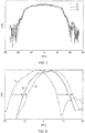
- FIGS. 5 and 6 are diagrams illustrating frequency characteristics of antenna 110 used in the present embodiment.
- FIG. 5 illustrates the frequency characteristics of antenna 110 in the horizontal direction
- FIG. 6 illustrates the frequency characteristics of antenna 110 in the elevation direction (height direction).
- a dash-dotted line in the drawing indicates characteristics for a case where a signal at frequency f1 is supplied to antenna 110
- a solid line in the drawing indicates characteristics for a case where a signal at frequency f2 (> f1) is supplied to antenna 110
- a dotted line in the drawing indicates characteristics for a case where a signal at frequency f3 (> f2) is supplied to antenna 110.
- antenna 110 is an antenna, a radiation angle of which in the horizontal direction hardly changes even when the frequency of a supplied signal is changed. Furthermore, antenna 110 is an antenna, the radiation angle of which in the elevation direction (height direction) changes according to the frequency of the supplied signal. As described above, the present embodiment uses antenna 110 with respect to which horizontal radiation hardly changes and only elevation radiation changes when the supplied frequency is changed. In practice, antenna 110 having such frequency characteristics may be implemented by performing designing by appropriately selecting the size and gap of the patches. Moreover, the antenna having the frequency characteristics as described above may be implemented by an antenna other than the patch antenna.
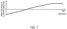
- FIG. 7 is a diagram illustrating how the radiation angle of antenna 110 changes in the elevation direction, where the frequency of the signal that is supplied to antenna 110 is increased over time. Specifically, an example of a case where an up-chirp signal is supplied to antenna 110 is illustrated. It can be seen from FIG. 7 that the radiation angle in the elevation direction is changed upward as the frequency is increased in one chirp.
- antenna 110 supplies a transmission signal as illustrated in FIG. 8 according to FM-CW method. Furthermore, measurement is performed taking M chirp signals as one measurement unit (one frame).
- FIG. 9 is a diagram illustrating frequency change of a single chirp signal (or in other words, a unit chirp signal), and the frequency of the chirp signal increases in period T up in single chirp signal period T_chirp, and decreases in period T_down.
- Control/processing section 101 performs sampling on a received single chirp signal into N pieces of sampling data as illustrated in FIG. 10 , and performs processing taking the N pieces of sampling data as a processing unit. That is, when N sample is taken as the number of samples in one chirp, L as the number of receiving systems (the number of receiving channels), and M_chirp as the number of chirps in one frame, the number of pieces of data in one measurement is N_sample ⁇ L ⁇ M chirp. After acquisition of the same, radar apparatus 100 performs data processing on the reception signal described below.
- FIG. 11 is a flowchart illustrating data processing on a reception signal that is performed by control/processing section 101.
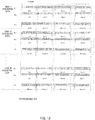
- FIG. 12 is a diagram for describing reception data that is used at the time of the data processing in FIG. 11 .
- reception data is input to control/processing section 101 in parallel from L (L channels) antennas Rx1 to RxL in the horizontal direction.
- Control/processing section 101 divides reception data of N sample into K pieces. In the example in FIG. 12 , N sample is divided into four pieces. Then, an FFT process is performed taking divided data as an FFT unit.
- control/processing section 101 performs division of data and a data selection process. At this time, control/processing section 101 divides data and selects data on the basis of the number of divisions and elevation correction data. That is, in the case where the number of divisions is four, N sample is divided into four pieces, and in the case where the number of divisions is K, N sample is divided into K pieces. Furthermore, because elevation change of antenna 110 when the frequency is increased/reduced is, in reality, not linear, and the elevation correction data is used to perform correction by such an amount.
- elevation change of antenna 110 tends to be small at a position where the frequency is close to maximum in one chirp, and thus, there is an interval between pieces of data used for the FFT process on that account, as illustrated in FIG. 12 .
- a selection interval timing of data used for the FFT process may be such that differences in average values of elevation are made approximately the same.
- control/processing section 101 corrects amplitude and angle in the horizontal direction on the basis of correction data for the amplitude and the angle.
- control/processing section 101 performs, on data of one FFT processing unit obtained by division as illustrated in FIG. 12 , range FFT processing in step S103, velocity FFT processing in step S104, and angle FFT processing in step S105, and thus calculates a distance, a velocity and an angle of a detected point in one elevation range.
- range FFT processing in step S103 range FFT processing in step S103
- velocity FFT processing in step S104 velocity FFT processing in step S104
- angle FFT processing in step S105
- Control/processing section 101 repeats the processes in steps S101 to S105 until a division number reaches K in step S106. That is, the processes in steps S101 to S105 are repeated K times.
- the distance, the velocity and the angle are thus calculated for detected points corresponding to the number of divisions (in the case of the present embodiment, the number of divisions, four, as illustrated in FIG. 12 ). In other words, the distance, the velocity and the angle are calculated for each single chirp signal, for the number of divisions.
- control/processing section 101 calculates an in-chirp presence probability.
- data (detected point) after FFT includes a distance and an angle, and can be plotted on a two-dimensional plane that takes the distance and the angle as coordinate axes. Furthermore, because data in one chirp is divided into K pieces, K two-dimensional planes are obtained for one chirp. Control/processing section 101 calculates the in-chirp presence probability of the detected point using the K two-dimensional planes.
- FIG. 13 illustrates detected points on the two-dimensional planes obtained in divided blocks in periods n, n+1, n+2 and n+3.
- a detected point indicated by a square in the drawing is present on all the planes, and thus, the presence probability is 100%.
- a detected point indicated by a triangle has a presence probability of 75%, and a detected point indicated by a circle has a presence probability of 50%.
- control/processing section 101 calculates the in-chirp presence probability of a detected point on the basis of the number of two-dimensional planes, among the K two-dimensional planes, on which the corresponding detected point is present. In other words, a presence probability of reflection in a chirp is calculated on the basis of whether there is reflection from a same position on the two-dimensional planes.
- a high in-chirp presence probability means a high probability of being an object with a height in the height direction, or in other words, an object that is an obstacle to a vehicle or the like.
- the present embodiment uses a principle that reflection remains for an object with a height or a tall object even when the radiation angle in the elevation direction is slightly changed, but reflection is removed for an object with no height or a low object when the radiation angle in the elevation direction is even slightly changed.
- control/processing section 101 performs output data selection process (filtering process). Specifically, a plurality of pieces of threshold data to be used for threshold determination regarding the presence probability are input, and output data is obtained for each piece of threshold data.
- the process in step S108 is described with reference to FIG. 14 .
- threshold 1 is a threshold for determining that a detected point is present on one or more two-dimensional planes
- threshold 2 is a threshold for determining that a detected point is present on two or more two-dimensional planes
- threshold 3 is a threshold for determining that a detected point is present on three or more two-dimensional planes
- threshold 4 is a threshold for determining that a detected point is present on four or more two-dimensional planes.
- antenna 110 that has frequency characteristics leading to a change in the radiation angle in the elevation direction according to the frequency that is supplied, a transmission signal forming section (control/processing section 101, oscillator 102, amplifier 103) that supplies a chirp signal to antenna 110, and a reception processing section (control/processing section 101) that obtains a detected point in each frequency band by using a reception signal corresponding to a transmission signal in each frequency band included in the chirp signal, and that obtains information in the height direction on the basis of whether the detected point is present or not over the plurality of frequency bands, and radar apparatus 100 that is capable of acquiring three-dimensional information may thus be implemented, without increasing complexity and size of the apparatus configuration. That is, according to the configuration of the present embodiment, information in the vertical direction (height direction) may be obtained with a simple configuration without complex switching between antennas nor signal processing.
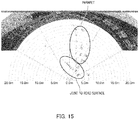
- FIG. 15 is a diagram illustrating an example of data that is obtained by a conventional radar apparatus
- FIG. 16 is a diagram illustrating an example of data that is obtained by radar apparatus 100 according to the present embodiment.
- a metal portion at a joint between a bridge on the ground and a road surface is observed together with a parapet of the bridge.
- the joint is treated as an obstacle.
- data of the parapet of the bridge is maintained while the joint between the bridge and the road surface is removed. That is, it is possible to leave only an object with a height, and thus, detection of an obstacle may be accurately performed.
- erroneous detection due to a ghost may be prevented. That is, when the radiation angle in the elevation direction is changed, a path is also changed, and the presence probability of a detected point that is erroneously detected due to a ghost is reduced, and a ghost is thereby prevented.
- the angle of a radio wave hitting an object is changed little by little.
- a reflection point that is removed from view at such a time is highly likely a ghost and not a real reflection point (or in other words, a reflection point of an actual object), and such a reflection point is removed in the present embodiment.
- information in the vertical direction may be obtained without increasing the number or area of antennas, and thus, three-dimensional information may be acquired using a small antenna that is advantageous for attachment to a vehicle or the like.
- an up-chirp signal as the chirp signal is described as an example, but it is needless to say that a down-chirp signal or both the up-chirp signal and the down-chirp signal may be used.
- FIGS. 13 and 14 in the embodiment described above, a case is described where a filtering process related to the detected point is performed on the basis of the number of two-dimensional planes on which corresponding detected points are present, but the filtering process related to the detected point may be performed, as illustrated in FIGS. 17 and 18 , on the basis of the number of two-dimensional planes on which corresponding detected points are continuously present. That is, the detected point may be filtered on the basis of the degree of continuity of the detected point present over a plurality of frequency bands. This increases a tracking accuracy with respect to a corresponding detected point, and clutters and ghosts may be even more suppressed.
- FIG. 17 illustrates detected points on two-dimensional planes obtained in divided blocks in periods n, n+1, n+2 and n+3. Successive detection of a square in the drawing is performed three times in a row, successive detection of a triangle is performed two times in a row, and successive detection of a circle is performed one time in a row.
- threshold 0 indicates zero or more times in a row
- threshold 1 indicates one or more times in a row
- threshold 2 indicates two or more times in a row
- threshold 3 indicates three or more times in a row.
- outputs (filtering outputs) corresponding to threshold 0 and threshold 1 images in which all of a square, a triangle and a circle (detected points) are shown are output.
- output corresponding to threshold 2 an image in which a square and a circle are shown is output.
- output corresponding to threshold 3 an image in which a square is shown is output.
- steps SI03-1, S104-1 and S105-1 indicate processing for a first divided block
- steps S103-K, S104-K and S105-K indicate processing for a K-th divided block.
- radar radiation may be performed in radiation ranges that are separate from one another in the elevation direction, by supplying, to antenna 110, transmission signals in a plurality of frequency bands that are separate from one another. Also in this case, three-dimensional information including information in the height direction may be obtained in the same manner as in the embodiment described above.
- the filtering process (suppression process) of the detected point is performed on the basis of the presence probability of the detected point when the radiation angle in the elevation direction is changed; but information about the height of an object may alternatively be obtained on the basis of presence/absence of the detected point when the radiation angle in the elevation direction is changed.
- the filtering process suppression process
- information about the height of the detected point may be calculated by changing the radiation angle of antenna 110 in the elevation direction by supplying, to antenna 110, transmission signals divided into a plurality of frequency bands f11, f12, f13, f14 and f15, and on the basis of distance information of the detected point detected in each frequency band and radiation angle information in each frequency band according to elevation frequency characteristics of the antenna.
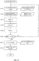
- FIG. 21 is a flowchart illustrating data processing on a reception signal performed to obtain three-dimensional information including the height information, where parts corresponding to those in FIG. 11 are denoted by the same reference signs.
- control/processing section 101 calculates the height of a detected object. Specifically, the height information of a detected point may be obtained from the distance information of the detected point calculated in step S103 and radiation angle data of antenna 110 corresponding to the frequency band where the detected point is present.
- control/processing section 101 generates three-dimensional information by combining the height information, the distance information, the velocity information and the angle information, and outputs the three-dimensional information.
- An apparatus (not illustrated) that receives such three-dimensional data may perform processes such as travel-over determination or travel-under determination using such three-dimensional data.
- the present invention is suitable for use in a vehicle-mounted radar apparatus, for example.
Landscapes
- Engineering & Computer Science (AREA)
- Radar, Positioning & Navigation (AREA)
- Remote Sensing (AREA)
- Physics & Mathematics (AREA)
- Computer Networks & Wireless Communication (AREA)
- General Physics & Mathematics (AREA)
- Electromagnetism (AREA)
- Radar Systems Or Details Thereof (AREA)
Applications Claiming Priority (2)
| Application Number | Priority Date | Filing Date | Title |
|---|---|---|---|
| JP2017191213A JP6923799B2 (ja) | 2017-09-29 | 2017-09-29 | レーダー装置 |
| PCT/JP2018/034787 WO2019065440A1 (ja) | 2017-09-29 | 2018-09-20 | レーダー装置 |
Publications (2)
| Publication Number | Publication Date |
|---|---|
| EP3690478A1 true EP3690478A1 (de) | 2020-08-05 |
| EP3690478A4 EP3690478A4 (de) | 2021-06-23 |
Family
ID=65901024
Family Applications (1)
| Application Number | Title | Priority Date | Filing Date |
|---|---|---|---|
| EP18862930.7A Withdrawn EP3690478A4 (de) | 2017-09-29 | 2018-09-20 | Radarvorrichtung |
Country Status (5)
| Country | Link |
|---|---|
| US (1) | US20210132210A1 (de) |
| EP (1) | EP3690478A4 (de) |
| JP (1) | JP6923799B2 (de) |
| CN (1) | CN111033309A (de) |
| WO (1) | WO2019065440A1 (de) |
Cited By (1)
| Publication number | Priority date | Publication date | Assignee | Title |
|---|---|---|---|---|
| EP3825719A1 (de) * | 2019-11-19 | 2021-05-26 | Samsung Electronics Co., Ltd. | Verfahren und vorrichtung mit messung der dreidimensionalen positionsbestimmung mittels radarsensor |
Families Citing this family (2)
| Publication number | Priority date | Publication date | Assignee | Title |
|---|---|---|---|---|
| US11309636B2 (en) * | 2019-12-18 | 2022-04-19 | Waymo Llc | Antenna structure for reducing beam squint and sidelobes |
| US11714187B2 (en) * | 2020-12-15 | 2023-08-01 | GM Global Technology Operations LLC | Frequency division multiple access in vehicle radar system |
Family Cites Families (31)
| Publication number | Priority date | Publication date | Assignee | Title |
|---|---|---|---|---|
| JPS6414749A (en) | 1987-07-08 | 1989-01-18 | Daicel Chem | Production of optical disk |
| JP2618124B2 (ja) | 1991-08-30 | 1997-06-11 | 株式会社エイ・ティ・アール光電波通信研究所 | 送信アレイアンテナのディジタルビーム制御装置 |
| JPH05107340A (ja) | 1991-10-14 | 1993-04-27 | Mitsubishi Electric Corp | レーダ情報合成装置 |
| JPH1078481A (ja) * | 1996-09-02 | 1998-03-24 | Mitsubishi Electric Corp | 航空機搭載用レーダ装置 |
| JP3045977B2 (ja) * | 1997-06-18 | 2000-05-29 | 本田技研工業株式会社 | Fm−cwレーダ装置 |
| JP2000206234A (ja) | 1999-01-13 | 2000-07-28 | Matsushita Electric Ind Co Ltd | Fm―cwレ―ダ装置 |
| JP2002236170A (ja) * | 2001-02-06 | 2002-08-23 | Fujitsu Ten Ltd | Fm−cwレーダ処理装置 |
| NL1020287C2 (nl) * | 2002-04-02 | 2003-10-03 | Thales Nederland Bv | Werkwijze voor meerdoelendetectie, met name voor toepassing in rondzoekradars met meerbundelvorming in elevatie. |
| DE10253808A1 (de) * | 2002-11-18 | 2004-07-29 | Daimlerchrysler Ag | Verfahren und Vorrichtung zur Erstellung eines Radarbildes mit einem frequenzmodulierten Dauerstrichradar |
| JP3736521B2 (ja) * | 2002-12-19 | 2006-01-18 | 株式会社デンソー | 車両用物体認識装置 |
| JP4232640B2 (ja) | 2004-01-21 | 2009-03-04 | トヨタ自動車株式会社 | 方向探知機 |
| JP3761888B2 (ja) * | 2004-02-16 | 2006-03-29 | 富士通テン株式会社 | 車載レーダ装置 |
| JP4551145B2 (ja) * | 2004-07-13 | 2010-09-22 | 富士通株式会社 | レーダ装置、レーダ装置の制御方法 |
| WO2007032234A1 (ja) * | 2005-09-14 | 2007-03-22 | Murata Manufacturing Co., Ltd. | レーダ装置 |
| JP2010112879A (ja) | 2008-11-07 | 2010-05-20 | Fujitsu Ten Ltd | レーダ送受信機、及びレーダ装置 |
| DE102008054624A1 (de) * | 2008-12-15 | 2010-06-17 | Robert Bosch Gmbh | FMCW-Radarsensor für Kraftfahrzeuge |
| DE102010001761A1 (de) * | 2010-02-10 | 2011-08-11 | Robert Bosch GmbH, 70469 | Radarsensor |
| DE102010064348A1 (de) * | 2010-12-29 | 2012-07-05 | Robert Bosch Gmbh | Radarsensor für Kraftfahrzeuge |
| CN102707266B (zh) * | 2012-05-24 | 2014-06-04 | 北京理工大学 | 一种具有抗干扰和多目标识别功能的雷达及其检测方法 |
| JP2014132250A (ja) * | 2013-01-07 | 2014-07-17 | Toyota Motor Corp | レーダ装置 |
| JP5602275B1 (ja) * | 2013-04-22 | 2014-10-08 | 三菱電機株式会社 | 車載用レーダ装置および車載用レーダ装置に適用される注目ターゲット検出方法 |
| JP6230849B2 (ja) * | 2013-08-26 | 2017-11-15 | 富士通テン株式会社 | アンテナ、レーダ装置、および、信号処理方法 |
| KR101896726B1 (ko) * | 2013-12-02 | 2018-09-07 | 주식회사 만도 | Cw 레이더 센싱 신호 및 fmcw 레이더 센싱 신호 기반의 주변 환경 감지 방법 및 장치 |
| KR102173994B1 (ko) * | 2014-03-18 | 2020-11-04 | 주식회사 만도 | 차량용 레이더의 조정 방법 및 제어 장치 |
| JP6321464B2 (ja) * | 2014-06-13 | 2018-05-09 | 株式会社デンソー | レーダ装置 |
| DE102014212281A1 (de) * | 2014-06-26 | 2015-12-31 | Robert Bosch Gmbh | Radarmessverfahren mit unterschiedlichen Sichtbereichen |
| CN104237879B (zh) * | 2014-09-09 | 2016-08-17 | 中国电子科技集团公司第二十八研究所 | 一种雷达系统中的多目标跟踪方法 |
| JP2016206158A (ja) * | 2015-04-28 | 2016-12-08 | 富士通テン株式会社 | レーダ装置、車両制御システムおよびレーダ装置の制御方法 |
| JP6598244B2 (ja) * | 2015-10-05 | 2019-10-30 | 株式会社デンソーテン | レーダ装置、レーダ装置の信号処理装置、および信号処理方法 |
| CN105353363B (zh) * | 2015-11-25 | 2017-06-09 | 四川九洲空管科技有限责任公司 | 一种利用时间分集和频率分集提高目标分辨力的方法 |
| JP5963988B1 (ja) | 2016-04-13 | 2016-08-03 | 株式会社オフィスナガトモ | 投てき器型知育器具 |
-
2017
- 2017-09-29 JP JP2017191213A patent/JP6923799B2/ja active Active
-
2018
- 2018-09-20 EP EP18862930.7A patent/EP3690478A4/de not_active Withdrawn
- 2018-09-20 WO PCT/JP2018/034787 patent/WO2019065440A1/ja not_active Ceased
- 2018-09-20 US US16/640,747 patent/US20210132210A1/en not_active Abandoned
- 2018-09-20 CN CN201880052940.1A patent/CN111033309A/zh not_active Withdrawn
Cited By (1)
| Publication number | Priority date | Publication date | Assignee | Title |
|---|---|---|---|---|
| EP3825719A1 (de) * | 2019-11-19 | 2021-05-26 | Samsung Electronics Co., Ltd. | Verfahren und vorrichtung mit messung der dreidimensionalen positionsbestimmung mittels radarsensor |
Also Published As
| Publication number | Publication date |
|---|---|
| CN111033309A (zh) | 2020-04-17 |
| JP6923799B2 (ja) | 2021-08-25 |
| EP3690478A4 (de) | 2021-06-23 |
| JP2019066288A (ja) | 2019-04-25 |
| WO2019065440A1 (ja) | 2019-04-04 |
| US20210132210A1 (en) | 2021-05-06 |
Similar Documents
| Publication | Publication Date | Title |
|---|---|---|
| US10852407B2 (en) | Imaging radar sensor with narrow antenna lobe and wide angle-detection range | |
| US10663571B2 (en) | Radar system and associated apparatus and methods | |
| US9190717B2 (en) | Radar sensor | |
| US7436348B2 (en) | Interferometer-type radar | |
| US9746554B2 (en) | Radar imaging system and related techniques | |
| US9140783B2 (en) | Radar device | |
| US20240159887A1 (en) | Beam steering radar with adjustable long-range radar mode for autonomous vehicles | |
| US11899132B2 (en) | Super-resolution enhancement techniques for radar | |
| US10871557B2 (en) | Velocity detection apparatus | |
| RU2496120C2 (ru) | Многофункциональная многодиапазонная масштабируемая радиолокационная система для летательных аппаратов | |
| US20210132210A1 (en) | Radar device | |
| JPWO2019049680A1 (ja) | レーダ装置およびそれを備える自動車 | |
| RU2571950C1 (ru) | Способ радиомониторинга радиомолчащих объектов | |
| RU2524399C1 (ru) | Способ обнаружения малоразмерных подвижных объектов | |
| KR102053881B1 (ko) | 지상배열안테나 시스템 및 지상배열안테나 시스템에서 상공의 탐지 영역의 이미지를 획득하는 방법 | |
| CN113330324B (zh) | 雷达装置和信号处理方法 | |
| RU2696274C1 (ru) | Малогабаритная многорежимная бортовая радиолокационная система для оснащения перспективных беспилотных и вертолетных систем | |
| Plšek et al. | FM based passive coherent radar: From detections to tracks | |
| Fabrizio et al. | Passive radar in the high frequency band | |
| KR101619064B1 (ko) | 능동 클러터 맵을 이용한 목표물 검출 방법 | |
| JP3614400B2 (ja) | レーダ信号処理装置及びレーダ信号処理方法 | |
| RU71781U1 (ru) | Пассивный радиолокационный комплекс | |
| JP2011196808A (ja) | レーダ装置 | |
| GB2582125A (en) | Radar device and method for identification of objects | |
| Zaumseil et al. | Radar-based near field environment perception using back projection algorithm |
Legal Events
| Date | Code | Title | Description |
|---|---|---|---|
| STAA | Information on the status of an ep patent application or granted ep patent |
Free format text: STATUS: THE INTERNATIONAL PUBLICATION HAS BEEN MADE |
|
| PUAI | Public reference made under article 153(3) epc to a published international application that has entered the european phase |
Free format text: ORIGINAL CODE: 0009012 |
|
| STAA | Information on the status of an ep patent application or granted ep patent |
Free format text: STATUS: REQUEST FOR EXAMINATION WAS MADE |
|
| 17P | Request for examination filed |
Effective date: 20200221 |
|
| AK | Designated contracting states |
Kind code of ref document: A1 Designated state(s): AL AT BE BG CH CY CZ DE DK EE ES FI FR GB GR HR HU IE IS IT LI LT LU LV MC MK MT NL NO PL PT RO RS SE SI SK SM TR |
|
| AX | Request for extension of the european patent |
Extension state: BA ME |
|
| DAV | Request for validation of the european patent (deleted) | ||
| DAX | Request for extension of the european patent (deleted) | ||
| A4 | Supplementary search report drawn up and despatched |
Effective date: 20210527 |
|
| RIC1 | Information provided on ipc code assigned before grant |
Ipc: G01S 13/42 20060101AFI20210520BHEP Ipc: G01S 7/03 20060101ALI20210520BHEP Ipc: G01S 13/34 20060101ALI20210520BHEP Ipc: G01S 7/02 20060101ALI20210520BHEP Ipc: G01S 13/931 20200101ALI20210520BHEP |
|
| STAA | Information on the status of an ep patent application or granted ep patent |
Free format text: STATUS: THE APPLICATION IS DEEMED TO BE WITHDRAWN |
|
| 18D | Application deemed to be withdrawn |
Effective date: 20220104 |