EP3690483B1 - Procédé de synthèse d'agencements de réseau d'antennes ou de sélection de forme d'onde dans un ensemble d'ouvertures mutuellement incohérentes pour applications radar et de radiofréquence - Google Patents
Procédé de synthèse d'agencements de réseau d'antennes ou de sélection de forme d'onde dans un ensemble d'ouvertures mutuellement incohérentes pour applications radar et de radiofréquence Download PDFInfo
- Publication number
- EP3690483B1 EP3690483B1 EP19155199.3A EP19155199A EP3690483B1 EP 3690483 B1 EP3690483 B1 EP 3690483B1 EP 19155199 A EP19155199 A EP 19155199A EP 3690483 B1 EP3690483 B1 EP 3690483B1
- Authority
- EP
- European Patent Office
- Prior art keywords
- apertures
- aperture
- radar
- optimization
- incoherent
- Prior art date
- Legal status (The legal status is an assumption and is not a legal conclusion. Google has not performed a legal analysis and makes no representation as to the accuracy of the status listed.)
- Active
Links
Images


Classifications
-
- G—PHYSICS
- G01—MEASURING; TESTING
- G01S—RADIO DIRECTION-FINDING; RADIO NAVIGATION; DETERMINING DISTANCE OR VELOCITY BY USE OF RADIO WAVES; LOCATING OR PRESENCE-DETECTING BY USE OF THE REFLECTION OR RERADIATION OF RADIO WAVES; ANALOGOUS ARRANGEMENTS USING OTHER WAVES
- G01S13/00—Systems using the reflection or reradiation of radio waves, e.g. radar systems; Analogous systems using reflection or reradiation of waves whose nature or wavelength is irrelevant or unspecified
- G01S13/88—Radar or analogous systems specially adapted for specific applications
-
- G—PHYSICS
- G01—MEASURING; TESTING
- G01S—RADIO DIRECTION-FINDING; RADIO NAVIGATION; DETERMINING DISTANCE OR VELOCITY BY USE OF RADIO WAVES; LOCATING OR PRESENCE-DETECTING BY USE OF THE REFLECTION OR RERADIATION OF RADIO WAVES; ANALOGOUS ARRANGEMENTS USING OTHER WAVES
- G01S13/00—Systems using the reflection or reradiation of radio waves, e.g. radar systems; Analogous systems using reflection or reradiation of waves whose nature or wavelength is irrelevant or unspecified
- G01S13/003—Bistatic radar systems; Multistatic radar systems
-
- G—PHYSICS
- G01—MEASURING; TESTING
- G01S—RADIO DIRECTION-FINDING; RADIO NAVIGATION; DETERMINING DISTANCE OR VELOCITY BY USE OF RADIO WAVES; LOCATING OR PRESENCE-DETECTING BY USE OF THE REFLECTION OR RERADIATION OF RADIO WAVES; ANALOGOUS ARRANGEMENTS USING OTHER WAVES
- G01S13/00—Systems using the reflection or reradiation of radio waves, e.g. radar systems; Analogous systems using reflection or reradiation of waves whose nature or wavelength is irrelevant or unspecified
- G01S13/02—Systems using reflection of radio waves, e.g. primary radar systems; Analogous systems
- G01S13/06—Systems determining position data of a target
- G01S13/42—Simultaneous measurement of distance and other co-ordinates
-
- G—PHYSICS
- G01—MEASURING; TESTING
- G01S—RADIO DIRECTION-FINDING; RADIO NAVIGATION; DETERMINING DISTANCE OR VELOCITY BY USE OF RADIO WAVES; LOCATING OR PRESENCE-DETECTING BY USE OF THE REFLECTION OR RERADIATION OF RADIO WAVES; ANALOGOUS ARRANGEMENTS USING OTHER WAVES
- G01S7/00—Details of systems according to groups G01S13/00, G01S15/00, G01S17/00
- G01S7/02—Details of systems according to groups G01S13/00, G01S15/00, G01S17/00 of systems according to group G01S13/00
- G01S7/28—Details of pulse systems
- G01S7/282—Transmitters
-
- G—PHYSICS
- G01—MEASURING; TESTING
- G01S—RADIO DIRECTION-FINDING; RADIO NAVIGATION; DETERMINING DISTANCE OR VELOCITY BY USE OF RADIO WAVES; LOCATING OR PRESENCE-DETECTING BY USE OF THE REFLECTION OR RERADIATION OF RADIO WAVES; ANALOGOUS ARRANGEMENTS USING OTHER WAVES
- G01S7/00—Details of systems according to groups G01S13/00, G01S15/00, G01S17/00
- G01S7/02—Details of systems according to groups G01S13/00, G01S15/00, G01S17/00 of systems according to group G01S13/00
- G01S7/35—Details of non-pulse systems
-
- G—PHYSICS
- G01—MEASURING; TESTING
- G01S—RADIO DIRECTION-FINDING; RADIO NAVIGATION; DETERMINING DISTANCE OR VELOCITY BY USE OF RADIO WAVES; LOCATING OR PRESENCE-DETECTING BY USE OF THE REFLECTION OR RERADIATION OF RADIO WAVES; ANALOGOUS ARRANGEMENTS USING OTHER WAVES
- G01S13/00—Systems using the reflection or reradiation of radio waves, e.g. radar systems; Analogous systems using reflection or reradiation of waves whose nature or wavelength is irrelevant or unspecified
- G01S13/88—Radar or analogous systems specially adapted for specific applications
- G01S13/885—Radar or analogous systems specially adapted for specific applications for ground probing
-
- G—PHYSICS
- G01—MEASURING; TESTING
- G01S—RADIO DIRECTION-FINDING; RADIO NAVIGATION; DETERMINING DISTANCE OR VELOCITY BY USE OF RADIO WAVES; LOCATING OR PRESENCE-DETECTING BY USE OF THE REFLECTION OR RERADIATION OF RADIO WAVES; ANALOGOUS ARRANGEMENTS USING OTHER WAVES
- G01S13/00—Systems using the reflection or reradiation of radio waves, e.g. radar systems; Analogous systems using reflection or reradiation of waves whose nature or wavelength is irrelevant or unspecified
- G01S13/88—Radar or analogous systems specially adapted for specific applications
- G01S13/93—Radar or analogous systems specially adapted for specific applications for anti-collision purposes
- G01S13/931—Radar or analogous systems specially adapted for specific applications for anti-collision purposes of land vehicles
Definitions
- the present invention relates to the design of optimal antenna arrays for radar and radio-frequency applications comprised of mutually incoherent apertures that enable high angular resolution and localization estimation with unpreceded flexibility in usage of available space, and without need to synchronize widely separated transmit and/or receive antenna elements, avoiding the phase errors associated to lack of synchrony, deformations, and vibrations, and making unnecessary techniques such as auto-focusing or blind calibration between apertures that would require several snapshots, while maintaining a combined effective array factor with low sidelobes, all these characteristics suitable for applications to automotive radar for advance driver assistance systems (ADAS), ground-penetrating radar, synthetic aperture radar, medical imaging, navigation systems, and communications.
- ADAS advance driver assistance systems
- the present invention also relates to a method for selection of waveform in a set of mutually incoherent apertures for radar and radio-frequency applications.
- High-resolution direction of arrival (DoA) estimation has crucial importance in most radar and communication systems.
- functions such as lane change assist and collision avoidance systems require high angular resolution in both forward and rear-facing radars to discern the lane of other vehicles and obstacles at long distances, especially at high speeds, cf. Fig. 1 .
- the necessary aperture size and number of transmit and receive elements increase the required space and complexity of the hardware to achieve synchronization, particularly at high frequencies, which poses a challenge on the overall design and raises the cost.
- the disclosed invention presents a design method for synthesis of antenna element positions of mutually incoherent apertures, which relaxes the constraints on required physical space and synchronization associated to prior art on design of coherent apertures, while ensuring a satisfactory performance of angular estimation.
- PRELIMINARIES MODEL FOR RADIATION PATTERN (Prior-Art)
- the physical model used in prior art for optimization of antenna element positions considers a geometric arrangement of antenna elements that by coherent transmission produces a so-called radiation or beam-pattern, referring to the power directionality when certain complex amplitudes are applied to the radiating antennas through a beam-former network.
- this model also represents the estimation method of beamforming or Delay-and-Sum wherein the powered received in any hypothetical direction is quantified for a given direction of the emitting or reflecting object.
- Fig. 2 shows the model of planar wave fronts for azimuth and elevation angle
- the ambiguity between a hypothesis ⁇ ' and the signal's true parameter &, with ⁇ ⁇ ⁇ ' is produced by a high value of AF( ⁇ , ⁇ ').
- a ( ⁇ ) is a function instead of a finite vector
- the scalar product in the corresponding Hilbert space is expressed as an integral.
- ⁇ min ⁇ max ⁇ R q is the rectangular domain, or field-of-view, with entry-wise lower and upper bounds.
- ⁇ . ⁇ p is the p-norm, for suitable p ⁇ [1, ⁇ ]
- MLW mainlobe width
- f Array collects the penalties on the sidelobe level f SLL in (5), and possibly a penalty on the MLW f MLW , and other penalty terms to include soft constraints
- f Array p 1 , ... , p M c : f SLL p 1 , ... , p M c + f MLW p 1 , ... , p M + ⁇
- S ⁇ R 3 ⁇ M represents the domain for the antenna positions, including spatial and minimum separation constraints to avoid electromagnetic coupling.
- in (1) by selecting b [ b 1 , ⁇ , b M ] equal to a FF ( u' ) .
- the radiation pattern i.e., the power received at spatial frequency or direction u when the beam is steered at direction u ', coincides with the ambiguity function AF ( u,u' ) .
- AF(u,u')
- , implies that the optimization in (5) is required only over the variable ⁇ u : u' - u ⁇ [ c ,2sin( ⁇ max )].
- the array factor can be expressed as a product in terms of antenna positions, which allows to create nulls at desired angles and control the sidelobe level, and for circular ring arrays, EP2949002A1 (see also WO2014114993A1 ), it is possible to derive some optimality conditions for the rings' radii.
- the far-field model has the advantage of fast processing using the Fast Fourier Transform (FFT) and other beamformers like MUSIC and ESPRIT.
- FFT Fast Fourier Transform
- MUSIC MUSIC
- ESPRIT angular variables
- using the far-field is not incompatible with using the angular variables ⁇ , ⁇ instead of the spatial frequencies [ u , v,w ] to parametrize the array factor.
- the design of the arrays can be performed using the parametrization in terms of [ ⁇ , ⁇ ], even if it fails to satisfy the symmetry relation in (13) which in any case is unnecessary for (5).
- the degrees of freedom for the optimization are the Tx and Rx antenna positions.
- the near-field model for DoA estimation is a more realistic in some applications like medical imaging and also for automotive radar using arrays of certain aperture.
- This model concerns the path of the signals from transmitters to object and back to receivers.
- the corresponding near-field steering vector for transmission a Tx NF n ⁇ r is defined similarly.
- the dependency of the near-field virtual steering vector on antenna positions is not through the virtual array in (15). Nonetheless, we can still refer to such coherent sets of Tx and Rx elements as a virtual aperture, which will be convenient when we define multiple such mutually incoherent apertures.
- the range r is a parameter that has a different treatment depending on the application and for design purposes it can be assumed in a certain interval.
- Analogous models include (a) DoA estimation under the far-field model using the electronic angles, and (b) Doppler estimation, where instead of having dependence on the antenna locations, there is a dependence on the carrier frequency and on the pulse repetition interval or non-uniform transmission times of the pulses.
- Another equivalent model is range estimation using a waveform with time-multiplexed or simultaneous frequencies, illustrated next. This waveform finds applications in ground penetrating radar [12], and SFCW for automotive radar [13] [14]. For simplicity, consider a transmitter and a receiver at the same location.
- PRELIMINARIES OTHER OPTIMIZATION METRICS FOR COHERENT APERTURES (Prior-Art)
- BCRB Bayesian Cramer-Rao Bound
- WWB Weiss-Weinstein Bound
- ZZB Ziv-Zakai bound
- Model (2) concerns a single coherent aperture because the signals of the different antennas are combined with known phases.
- the literature on array design considers the optimization of antenna element positions only in said case of coherent apertures [2] [3] [4].
- Work [21] was the first to consider this problem, and more recently the available computational power has popularized nonlinear global optimization methods such as genetic algorithms, particle swarm optimization, and simulated annealing [22].
- the optimization has also been performed for non-planar arrays, including conformal arrays [8].
- prior patent applications again only the case of coherent arrays is studied, as we outline next with some exemplary works.
- US3877033A describes a synthesis method of non-uniform arrays with uniform amplitudes (following the seminal work by the author in [21]) with a much lower sidelobe-level of the radiation pattern than the uniform counterparts, based on a factorization of the array factor, normally given by a sum of cosines for symmetric arrays, in terms of a multiplication of cosines in terms of the element positions, which yields a sequential and computationally fast method for optimal placement of an arbitrary number of antenna elements.
- WO2009140998A1 describes a method for thinning a given array (i.e., removing elements from an initially uniform array) using as optimization metric a combination of the angular estimation performance and the sidelobe level.
- the former is quantified in terms of the MSE or a lower bound thereof such as the CRB.
- EP2949002A1 (see also WO2014114993A1 ) describes a method for joint optimization of element positions and dimensions for planar sparse arrays, especially circular ring arrays.
- the optimization method makes some assumptions about the structure of the array to employ certain analytic optimality conditions.
- CN105426578B presents an optimization method for planar arrays for MIMO Synthetic Aperture Radar. The optimization of SLL and MLW is performed using genetic algorithms.
- the digital signal processing can optionally include match-filtering for range-Doppler processing or, typically in automotive radar, 2D-FFT.
- the following signal model can include spatiotemporal sampling and is not restricted to angle estimation, thus broadening the applicability of the disclosed invention for design of optimal non-uniform sampling and illumination with stepped frequencies under incoherency.
- the measurements are grouped for each coherent aperture, and can refer to time, frequency, or spatial samples.
- each virtual aperture l ⁇ ⁇ 1, ..., L ⁇ is defined as follows.
- the noise after previous filtering is denoted by w l ⁇ C m l and its distribution does not play a role unless explicitly mentioned in embodiment 3 where we introduce the likelihood under Gaussian models. That is, we consider the deterministic ambiguity function associated to the geometry of the samples.
- the signal models for each of the blocks, ⁇ a l ⁇ k ⁇ C m l ⁇ , are expressed in a common-reference frame, and can correspond to angle of arrival estimation under far-field or near-field models for narrow-band sources, Doppler estimation with non-uniform pulse repetition intervals [23], and range estimation [23] [11].
- [15] presents a radar system architecture based on Compressed Sensing for high range resolution [30], and ISAR, where only specific frequencies are generated, thus using the spectrum more efficiently and reducing the rate of sampling data.
- [31] explains a method for measurement acquisition and delay estimation based on Doppler focusing for increasing SNR and guaranteeing sparsity in fast-time domain (i.e., range domain).
- This work estimates the delay using Compressed Sensing with a set of Fourier coefficients, which can be obtained via direct sampling [32], or sampling different spectral bands using a sub-Nyquist measurement-acquisition process denominated Xampling, and then matching the Fourier coefficients digitally [33].
- Other design techniques for sub-sampling a signal include multicoset sampling [34], which is amenable to CS techniques [35]. This model has been used for the optimization of spatially variant apodization (tapering) assuming coherency [36].
- US9448302B2 (Method for operating a MIMO radar), related to [39] [40], presents a time-multiplexed schema where transmission instants are optimized according to a mathematical expression based on the Cramer-Rao Bound for joint estimation of DoA and Doppler assuming a coherent group of antennas. This accomplishes a reduction of the effect of movement and consequent Doppler frequency shift on DoA estimation accuracy when all the antennas of a MIMO system are used with time-domain multiplexing.
- a synthesis of antenna array layouts is described based on mutually incoherent apertures in terms of an optimization problem for given constraints on the number of mutually incoherent apertures, the total number of Tx and Rx elements, the maximum size of each aperture, and the field-of-view.
- Other design hyper-parameters for near-field models may include the set of ranges over which the metric is averaged.
- the design method includes the provision of a metric with ambiguity functions formulated for Block Orthogonal Matching Pursuit (BOMP), Tropp's Exact Recovery Condition (ERC), and Maximum Likelihood, for a signal model that includes random initial phases between apertures, and the selection of transmit and receive antenna locations according to said metric based on optimization of the corresponding ambiguity functions.
- the optimization is performed such that a sidelobe level (and/or features dependent on the sidelobe level) associated to said ambiguity functions over a number of dimensions corresponding to one or several parameters of interest, including azimuth and/or elevation, is minimized.
- the proposed method for selection of waveform accordingly includes the provision of a metric with ambiguity functions based on a signal model that includes random initial phases between apertures, and the selection of frequencies and/or pulse transmission times according to said metric based on optimization of the ambiguity functions such that a sidelobe level (and/or features dependent on the sidelobe level) associated to said ambiguity functions over a number of dimensions corresponding to one or several parameters of interest, including range and/or Doppler, is minimized.
- the principle of the invention for design of array layouts of mutually incoherent apertures is the following.
- group-sparse reconstruction algorithms and other beamformers exhibit an improved estimation performance because the design method allows to optimize the resolution of the mutually incoherent apertures by using more effectively the available space without the need to keep a low sidelobe level in each individual aperture thanks to the mutual cancellation of sidelobes.
- the proposed method and exemplary array layouts are particularly suited, given the above benefits, for design of a constellation of incoherent apertures for automotive radar, optimized for short, medium and long range functionalities and possibly with full 360° coverage to enable at low cost all advance driving assistant systems, from lane change assist, to collision warning and emergency braking. Nonetheless, it can also find applications in airborne and satellite radar, synthetic aperture radar, remote sensing, communications, and navigation systems.
- PRELIMINARIES GROUP-SPARSE RECONSTRUCTION FOR INCOHERENT APERTURES (Prior-Art)
- the estimation of the parameter vectors ⁇ 1 , ⁇ 2 , ... , ⁇ K ⁇ R q for each of the K targets for the general signal model (19) can be formulated as a group-sparse reconstruction problem, which entails fitting the measurements of each virtual aperture by a sparse linear super-position of single-source predictions selected from an over-complete dictionary of hypotheses.
- the quantity x ⁇ ⁇ R N can be interpreted as the amplitude map for the parameter of interest over the N-grid.
- the measurement fidelity constraints (20) do not couple the phase differences between mutually incoherent virtual apertures because these are assumed arbitrary due to lack of synchronization, vibrations, etc.
- BOMP group-sparse reconstruction algorithms analog to ones for standard sparsity.
- BOMP has the following strategy for group selection (or block of atoms) in the case of incoherent sensors [27].
- steps (22) and (23) are the only ones that combine information among apertures and also the relevant steps for the motivation of our design method.
- the matched-filter computations in (22) are the basis of other reconstruction algorithms such as Matching Pursuit (MP) [45] or iterative thresholding algorithm (ITA) [46].
- MP Matching Pursuit
- ITA iterative thresholding algorithm
- the fundamental principle is the combined matched filter response, which is used in BOMP for atom selection (23), and is also used in algorithms such as MP or ITA for the gradient direction (cf. [47] for a unified description of these methods and efficient implementations).With these preliminaries, we are in a condition to describe the invention.
- Fig. 6 shows an example of the effect of mutual sidelobe cancellation as a result of optimization (25).
- the optimization uses square antenna patterns over the FoV ⁇ 60°, and uses the far-field model.
- the configuration was pre-selected to be a central 3x4 MIMO aperture, and two "satellite" apertures on the sides with 4 Rx elements each, all linear along the y-axis and with the same perpendicular orientation.
- the maximum available size for each aperture was, from left to right, 4cm, 7cm, and 4 cm. Note that in general the number of mutually incoherent apertures results from all the combinations of Tx and Rx coherent sub-arrays, but in this example there are Tx elements only in the central aperture, while there are receivers in all three apertures. Consequently, the mutually incoherent virtual apertures are then defined by the Tx,Rx-MIMO subarrays (Center-Left), (Center-Center), and (Center-Right).
- the final sizes after the optimization of the subarrays is indicated in the legend: 1.9cm for Rx sub-array on the left, 3cm and 2.3cm for the Tx and Rx sub-arrays on the center, and 1.6cm for the Rx sub-array on the right.
- the plot shows the individual AF of the three mutually incoherent virtual apertures and the combined effective AF according to (24), whose SLL is optimized. As a result of the optimization we observe that the sidelobes of the individual AF are mutually compensated in the combined AF.
- Fig. 3 shows schematically how the design of the front-end antennas of the mutually incoherent apertures fits into a processing chain, in principle for radar and radio-frequency applications, where digital beamforming is done with group-sparse reconstruction, cf. Section PRIOR ART ON PROCESSING WITH MUTUALLY INCOHERENT APERTURES.
- the optimal design by inducing mutual sidelobe cancellation among matched filter responses of the individual virtual apertures, reduces ambiguity in the selection of the group of hypotheses that maximizes the combined response.
- Near-field models can be used for embodiment 1A as follows.
- the range can be obtained in a number of ways, e.g., using FMCW processing typical in automotive.
- the range of the objects can be assumed in any interval of values of interest. Tapering weights can also be incorporated as in embodiment 1C.
- the computational cost of the min-max optimization (27)-(25) ultimately depends on the complexity of evaluation of the observation model, which grows linearly with the number of virtual pairs of Tx and Rx elements and consequently with the number of incoherent apertures, and therefore the complexity is comparable to the case of coherent array design.
- the observation model for far-field steering vector (11) is slightly faster to evaluate than the model of near-field steering vector (16).
- ERC is formulated for sparse signals with a specific support, rather than for all sparse signals simultaneously, which is sufficient for design because typically the models used for design assume a single target.
- the ERC is desired to be low to reduce correlation between atoms in A and atoms not in A. That is, max n ⁇ ⁇ ⁇ A ⁇ + a n ⁇ 1 quantifies the ambiguity between hypotheses with indexes in A and out of A.
- the block-diagonal structure accounts for the random phase between the two apertures, and we make the group-sparsity partition of columns wherein two columns belong to the same class if they correspond to the same hypothesis (that is, even though the ERC is defined for standard sparsity with 1-norm, we consider a partition over groups of columns corresponding to the same hypotheses). Without loss of generality, we assume that the array models are expressed in a common reference frame, so that corresponding hypotheses for each aperture have the same index.
- the AFs are added with a relative importance factor proportional to 1 m l , i.e., inversely with the number of samples (or antennas), and ii) the fact that the 1-norm is used in the definition of ERC (instead of the 2-norm as in the group-sparsity norm ⁇ x ⁇ 2,1 ), is responsible for the fact that the AFs are added linearly and not quadratically in contrast with the metric in embodiment 1.
- the metric of embodiment 1 has a direct relationship to atom/group selection in BOMP through the combined matched-filter response (in turn related to gradient steps of MP and ITA in their extension to incoherent apertures) but this embodiment suggests, among other things, that the atom/group selection criterion of BOMP can be modified to exploit other optimality conditions.
- the concentrated log-likelihood for one snapshot results from solving s ( l ) for each aperture l , as follows, min s l ⁇ C ⁇ y l ⁇ a l ⁇ s l ⁇ 2 .
- the synthesis of antenna positions for each of the apertures can be defined as in (27).
- the signal model for individual apertures a ( l ) ( ⁇ ) is general.
- far-field and near-field models can be used for the optimization as described in embodiment 1.
- Previous embodiments characterize the optimal array layouts of multiple apertures and optional optimal tapering in such a way that posterior processing is enhanced even when information is combined incoherently.
- the proposed design optimization has been motivated by group-sparse reconstruction with BOMP in embodiment 1, recovery conditions for Compressed Sensing in embodiment 2, and Maximum likelihood in embodiment 3.
- Fig. 7 illustrates an instance of four mutually incoherent apertures in the front and on the rear of a vehicle, where the FoVs are represented with cones whose radii illustrate the detection range and overlapping areas are regions where optimization of antenna elements is coupled between apertures.
- the driving principle is parallel to the one in previous embodiments.
- a number of Tx, Rx antenna elements were optimally placed in multiple mutually incoherent apertures with efficient use of the available space thanks to mutual sidelobe cancellation between apertures.
- the synthesis method concerns stepped-frequency pulses or stepped-frequency continuous-waves (SFCW) and enables a reduced number of steps/pulses in each coherent bandwidth, which reduces measurement time and allows to avoid occupied bands of the spectrum.
- the resulting sparse waveform synthesis can be employed for range (and possibly Doppler) estimation using efficient Compressed Sensing algorithms including BOMP, similarly to the beamforming process based on group-sparse filtering in Fig. 3 .
- this optimization has applications in ground penetrating radar, spectrum management, and SFCW for automotive radar.
- all frequency steps pulse or chirps
- the design according to this model presumes a processing mechanism that allows for incoherent combination of signals. That is, in the processing of signals when the angle of the targets is initially unknown (e.g., for range and/or Doppler estimation), using the proposed design of mutually incoherent apertures and waveform synthesis, the contribution to the phase of the frequency samples a ( l ) ( r k ), a ( l' ) ( r k ) collected by any two pairs (Tx ( l ) ,Rx ( l ) ), (Tx ( l ') ,Rx ( l ') ) in different virtual apertures l,l', due to the unknown angle of each target k and the diversity of antenna positions, is factored out and regarded as random as part of s k l and s k l ′ , cf. (19). Therefore, the proposed design is compatible with the design setup that we advocate, and, by improving the associated ambiguity function for the mutually in
- Fig. 8 illustrates a scenario of waveforms for Tx elements in mutually incoherent apertures.
- Each transmitter has available a bandwidth for selection of SFCWs.
- a stepped frequency waveform or set of simultaneous frequencies can be selected, and the proposed embodiment describes the combined optimal selection across all mutually incoherent bandwidths.
- Transmission times in TDM MIMO can be designed across multiple incoherent slow-time sequences to optimize non-ambiguous Doppler bandwidth and resolution.
- all transmitters can be considered as incoherent in cases including a) they are actually in incoherent apertures as described in previous embodiments, and b) cases where is desirable to decouple Doppler and DoA because there is an unknown phase difference between transmitters caused by the unknown target angle.
- transmission times of the pulse/chirps for each transmitter can be optimized to achieve mutual sidelobe cancellation in Doppler domain under incoherency according to the following, min t 1 , ... , t M f SLL t 1 , ... , t M c s .
- T l ⁇ R is the available time for the transmitter l
- f SLL [ t 1 , ..., t M ]; c ) is obtained as in (24)-(25) in terms of the ambiguity functions for Doppler estimation.
- the signal model for Doppler estimation in terms of slow-time samples after preliminary range processing, at a given range frequency bin, is mathematically equivalent to the steering vector of the far-field model (11). As time orthogonality is necessary for TDM MIMO waveforms, no simultaneous chirps or pulses should be allowed between different transmitters, which is captured by the domain
- This embodiment addresses the problem in TDM MIMO with several Tx elements where the long dwelling time between consecutive chirps transmitted by the same Tx element, reduces the maximum non-ambiguous Doppler frequency, thus making the system unsuitable for high velocities of the target.
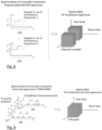
- Fig. 9 illustrates the optimization of transmission times for non-simultaneous chirps for two generic mutually incoherent transmitters over their respective coherent processing intervals, and also depicts the associated data cube.
- the diagram shows an arbitrary sparse antenna configuration and an exemplary sequence of FMCW chirps in frequency-time axes, emphasizing the design of the transmission times.
- the corresponding designs are suitable for processing of incoherent signals using algorithms such as MP or ITA for incoherent aperturtes or BOMP which are reasonably efficient as pointed out in the preliminaries..
- n ⁇ ⁇ R 3 cos ⁇ sin ⁇ , sin ⁇ ,sin ⁇ , cos ⁇ .
- u sin( ⁇ ) Electronic angle when array is linear in the y axis (more properly, the v-component of n ⁇ ) r > 0 Range, distance to target.
- ⁇ , ⁇ k ⁇ R q Generic parameter vector, which can refer to the parameter vector of target k .
- a ⁇ ⁇ C M Generic signal (spatiotemporal sampling) model can be particularized to Tx or Rx steering vectors a Tx ( ⁇ ), a Rx ( ⁇ ), or virtual a Virt ( ⁇ ) (.) FF , (.) NF Scripts to represent far- and near-field, respectively.
- Super-index ( l ) indicates l th aperture. It can refer to physical apertures l ⁇ ⁇ 1, ..., L ' ⁇ , or virtual apertures l ⁇ ⁇ 1, ..., L ⁇ .
- the virtual apertures are combinations of Tx and Rx sets in each of the physical apertures.
- L,L',L" Number of physical apertures, mutually incoherent virtual apertures, and number of mutually incoherent sets of stepped frequencies, respectively.
- m Virt l m Tx l ⁇ m Rx l
- m Virt : m Virt 1 + ⁇ + m Virt L . w , w ( l ) , w Total Weights for tapering in three cases, generic, in virtual aperture l , and across all virtual apertures.
- x l ⁇ C N Sparse reconstruction coefficient vector over hypotheses ⁇ ⁇ 1 , ... , ⁇ N ⁇ .
- AF ( ⁇ , ⁇ ' ⁇ > 0 Standard ambiguity function defined for a generic signal model a ( ⁇ ) AF ⁇ , ⁇ ′ : a ⁇ H a ⁇ ′ .
- AF ( l ) ( ⁇ , ⁇ ' ) Ambiguity function associated to the l th aperture.
- AF BOMP ( ⁇ , ⁇ ' ) Combined ambiguity function over all apertures for BOMP.
- AF ERC ( ⁇ , ⁇ ' ) Combined ambiguity function over all apertures for ERC.
- AF ML ( ⁇ , ⁇ ' ) Combined ambiguity function over all apertures for maximum likelihood.
Landscapes
- Engineering & Computer Science (AREA)
- Radar, Positioning & Navigation (AREA)
- Remote Sensing (AREA)
- Physics & Mathematics (AREA)
- Computer Networks & Wireless Communication (AREA)
- General Physics & Mathematics (AREA)
- Electromagnetism (AREA)
- Radar Systems Or Details Thereof (AREA)
- Variable-Direction Aerials And Aerial Arrays (AREA)
Claims (14)
- Procédé de synthèse des agencements de réseaux d'antenne pour des applications radar et radiofréquence, dans lequel procédé lesdits agencements sont formés pour comprendre un nombre donné d'ouvertures mutuellement incohérentes, dans lequel pour les spécifications d'espace données pour chaque ouverture, un nombre d'antennes d'émission et de réception et de champ(s) de vision des ouvertures, un procédé de conception est appliqué, comprenant de :- fournir une métrique avec des fonctions d'ambiguïté basées sur un modèle de signal qui inclut des phases initiales aléatoires entre les ouvertures, et- sélectionner des emplacements d'antenne de transmission et de réception en fonction de ladite métrique basée sur l'optimisation des fonctions d'ambiguïté de sorte qu'un niveau de lobe secondaire et/ou des caractéristiques fonction du niveau de lobe secondaire associé à ladite fonction d'ambiguïté sur un certain nombre de dimensions correspondant à un ou plusieurs paramètres d'intérêt, y compris l'azimut et/ ou l'élévation, est minimisé.
- Procédé selon la revendication 1, caractérisé en ce que la métrique fournie correspond à une fonction d'ambiguïté basée sur la sélection d'atome/groupe du procédé de reconstruction group-sparse à poursuite de correspondance orthogonale de bloc.
- Procédé selon la revendication 1, caractérisé en ce que chaque fonction d'ambiguïté pour les ouvertures mutuellement incohérentes est pondérée par un certain nombre de paires d'émission-réception dérivées de la condition de récupération exacte de TROPP, ou pondérées par un espace maximal associé à chaque ouverture.
- Procédé selon la revendication 1, caractérisé en ce que la métrique fournie correspond à une fonction d'ambiguïté basée sur une estimation de vraisemblance maximale.
- Procédé selon l'une ou l'autre des revendications 1 à 4, caractérisé en ce qu'un modèle en champ proche est utilisé dans la métrique moyenne sur un ensemble de plages souhaité.
- Procédé selon l'une ou l'autre des revendications 1 à 5, caractérisé en ce que les sous-ensembles desdites ouvertures mutuellement incohérentes sont optimisés pour des plages et des champs de vision distincts, afin de produire des agencements multifonctionnels.
- Procédé selon l'une ou l'autre des revendications 1 à 5, caractérisé en ce que l'optimisation prend en compte, en plus des emplacements d'antenne dans chaque ouverture, un ensemble de poids effilés qui sont appliqués numériquement dans le post-traitement des signaux.
- Procédé de sélection de forme d'onde, incluant la sélection de fréquences de fréquences transmises simultanées ou de formes d'ondes de fréquence par paliers et/ou de temps de transmission d'impulsions, pour des émetteurs dans un ensemble d'ouvertures mutuellement incohérentes pour des applications radar et de radiofréquence,
dans lequel pour les spécifications données de bande passante de chaque ouverture ou contraintes sur les temps de transmission dans le cas de TDM MIMO et le nombre d'éléments de transmission, la procédé comprend de :- fournir une métrique avec des fonctions d'ambiguïté basées sur un modèle de signal qui comprend des phases initiales aléatoires entre les ouvertures, et- sélectionner des fréquences et/ou des temps de transmission d'impulsions selon ladite métrique sur la base de l'optimisation des fonctions d'ambiguïté de telle sorte qu'un niveau de lobe secondaire et/ou des caractéristiques fonction du niveau de lobe secondaire associé à ladite fonction d'ambiguïté sur un certain nombre de dimensions correspondant à un ou plusieurs paramètres d'intérêt, y compris la plage et/ou le doppler, soit minimisé. - Procédé selon la revendication 8, caractérisée en ce que la métrique fournie correspond à une fonction d'ambiguïté basée sur la sélection d'atome/groupe du procédé de reconstruction group-sparse à poursuite de correspondance orthogonale de bloc.
- Procédé selon la revendication 8, caractérisé en ce que chaque fonction d'ambiguïté pour les ouvertures mutuellement incohérentes est pondérée par un certain nombre de paires d'émission-réception dérivées de la condition de récupération exacte de TROPP, ou pondérées par un espace maximal associé à chaque ouverture, ou pondérée par une bande passante maximale, ou un intervalle de traitement cohérent, associée à chaque ouverture.
- Procédé selon la revendication 8, caractérisé en ce que la métrique fournie correspond à une fonction d'ambiguïté basée sur une estimation de vraisemblance maximale.
- Système radar comprenant- un agencement d'antenne avec au moins deux ouvertures mutuellement incohérentes synthétisées avec le procédé selon une ou plusieurs des revendications 1 à 7, et- une unité d'évaluation, ladite unité d'évaluation étant adaptée pour effectuer un traitement des signaux de mesure des au moins deux ouvertures afin de détecter des objets dans une scène.
- Système radar selon la revendication 12, caractérisé ladite unité d'évaluation est adaptée pour effectuer ledit traitement via une reconstruction group-sparse.
- Système radar selon la revendication 12 ou 13, caractérisé en ce que le système radar comprend un générateur de forme d'onde, ledit générateur de forme d'onde étant conçu pour générer une forme d'onde de signal pour les émetteurs desdites ouvertures mutuellement incohérentes sur la base du procédé selon une ou plusieurs des revendications 8 à 11.
Priority Applications (1)
| Application Number | Priority Date | Filing Date | Title |
|---|---|---|---|
| EP19155199.3A EP3690483B1 (fr) | 2019-02-04 | 2019-02-04 | Procédé de synthèse d'agencements de réseau d'antennes ou de sélection de forme d'onde dans un ensemble d'ouvertures mutuellement incohérentes pour applications radar et de radiofréquence |
Applications Claiming Priority (1)
| Application Number | Priority Date | Filing Date | Title |
|---|---|---|---|
| EP19155199.3A EP3690483B1 (fr) | 2019-02-04 | 2019-02-04 | Procédé de synthèse d'agencements de réseau d'antennes ou de sélection de forme d'onde dans un ensemble d'ouvertures mutuellement incohérentes pour applications radar et de radiofréquence |
Publications (2)
| Publication Number | Publication Date |
|---|---|
| EP3690483A1 EP3690483A1 (fr) | 2020-08-05 |
| EP3690483B1 true EP3690483B1 (fr) | 2023-05-03 |
Family
ID=65278294
Family Applications (1)
| Application Number | Title | Priority Date | Filing Date |
|---|---|---|---|
| EP19155199.3A Active EP3690483B1 (fr) | 2019-02-04 | 2019-02-04 | Procédé de synthèse d'agencements de réseau d'antennes ou de sélection de forme d'onde dans un ensemble d'ouvertures mutuellement incohérentes pour applications radar et de radiofréquence |
Country Status (1)
| Country | Link |
|---|---|
| EP (1) | EP3690483B1 (fr) |
Families Citing this family (44)
| Publication number | Priority date | Publication date | Assignee | Title |
|---|---|---|---|---|
| US11520004B2 (en) * | 2019-11-12 | 2022-12-06 | Steradian Semiconductors Private Limited | System and method for generating point cloud data in a radar based object detection |
| WO2021168591A1 (fr) * | 2020-02-28 | 2021-09-02 | Novamera Inc. | Appareil pour géoradar et procédé |
| CN112070697B (zh) * | 2020-09-07 | 2024-01-19 | 北京环境特性研究所 | 一种基于逆二维像的局部散射特性评估方法及装置 |
| US11762079B2 (en) | 2020-09-30 | 2023-09-19 | Aurora Operations, Inc. | Distributed radar antenna array aperture |
| US11899127B2 (en) | 2020-09-30 | 2024-02-13 | Aurora Operations, Inc. | Virtual antenna array with distributed aperture |
| CN112421242B (zh) * | 2020-11-06 | 2022-04-19 | 中国电子科技集团公司第三十八研究所 | 一种极宽带综合口径阵列天线的布阵方法 |
| JP7853991B2 (ja) * | 2021-02-08 | 2026-04-30 | シメオ ゲゼルシャフト ミット ベシュレンクテル ハフツング | レーダシステムおよび対応する方法 |
| CN113050027B (zh) * | 2021-03-08 | 2023-09-19 | 浙江大学 | 一种幅相误差情况下基于稀疏重构的波达方向估计方法 |
| CN113037349B (zh) * | 2021-03-12 | 2022-06-10 | 重庆邮电大学 | Irs辅助miso系统中基于交替迭代的物理层安全设计方法 |
| CN113051739B (zh) * | 2021-03-17 | 2023-08-18 | 电子科技大学长三角研究院(衢州) | 一种基于稀疏约束的鲁棒性自适应处理方法 |
| CN113075622B (zh) * | 2021-03-30 | 2023-08-15 | 重庆三峡学院 | 一种雷达通信一体化中多用户通信的发射波束赋形方法 |
| CN113359095B (zh) * | 2021-04-27 | 2022-10-14 | 电子科技大学 | 一种相干被动mimo雷达克拉美罗界的计算方法 |
| CN113252998B (zh) * | 2021-04-30 | 2022-12-13 | 西南电子技术研究所(中国电子科技集团公司第十研究所) | 相控阵天线和、差波束信号电平的平坦度优化方法 |
| CN113225758B (zh) * | 2021-05-10 | 2023-09-01 | 中国科学院微小卫星创新研究院 | 一种基于协作关系的智能反射面通信增强方法 |
| CN113391259B (zh) * | 2021-05-17 | 2023-08-11 | 西安电子科技大学 | 基于非参数迭代自适应的机载三维异构阵doa估计方法 |
| CN113468733B (zh) * | 2021-06-23 | 2023-05-16 | 北京邮电大学 | 超宽带平面波合成器的稀疏阵列重构方法、装置及设备 |
| CN113466797B (zh) * | 2021-06-24 | 2023-04-28 | 电子科技大学 | 基于杂波脊匹配稀疏恢复的双基sar空-时杂波抑制方法 |
| CN115696437A (zh) * | 2021-07-28 | 2023-02-03 | 哈尔滨工业大学(深圳) | 基于irs的无线能量传输网络的用户总速率最大化方法 |
| CN113791392B (zh) * | 2021-08-05 | 2023-11-07 | 中国人民解放军空军工程大学 | 一种基于频控阵对全向比幅单脉冲测向系统的欺骗方法 |
| CN113613273B (zh) * | 2021-08-09 | 2023-12-26 | 浙江中蓝创新科技股份有限公司 | 一种智能超表面辅助无线供电网络的稳健能效优化方法 |
| CN113960592B (zh) * | 2021-09-07 | 2024-08-06 | 西安电子科技大学 | 一种共形阵列低旁瓣波束形成方法 |
| CN115524680A (zh) * | 2021-10-27 | 2022-12-27 | 纵目科技(上海)股份有限公司 | 预期mimo雷达系统的获取/角度的估计方法、系统、设备及介质 |
| CN114336076B (zh) * | 2022-01-13 | 2025-09-19 | 北京工业大学 | 一种超薄宽带rcs缩减编码电磁超表面 |
| CN114896713B (zh) * | 2022-01-30 | 2024-08-20 | 北京理工大学 | 基于多目标分解分层遗传算法的雷达多元天线阵列设计方法 |
| CN114675238B (zh) * | 2022-02-24 | 2023-11-03 | 中国人民解放军国防科技大学 | 一种雷达通信一体化波形直接优化方法和系统 |
| CN114740434B (zh) * | 2022-03-07 | 2024-05-14 | 中国人民解放军空军工程大学 | 一种等距分布子阵列系统及抗伴飞式干扰的方法 |
| CN114609592B (zh) * | 2022-03-21 | 2023-05-05 | 电子科技大学 | 一种mimo雷达虚拟稀疏阵列优化布阵方法 |
| CN115372891B (zh) * | 2022-07-22 | 2024-12-13 | 同济大学 | 一种基于改进的离网格稀疏贝叶斯学习的doa估计方法 |
| CN115310341B (zh) * | 2022-08-19 | 2024-07-02 | 中国电子科技集团公司第五十四研究所 | 一种深空测控天线组阵布局优化设计方法 |
| CN115361042B (zh) * | 2022-10-17 | 2022-12-23 | 中国人民解放军国防科技大学 | 一种基于mimo阵列的发射波形优化方法与系统 |
| CN115932818A (zh) * | 2022-12-27 | 2023-04-07 | 西安天伟电子系统工程有限公司 | 正交波形生成方法、装置、设备及存储介质 |
| CN116305821B (zh) * | 2023-02-14 | 2025-05-30 | 西安电子科技大学 | 一种雷达通信一体化波形互补失配滤波器组的设计方法 |
| CN115825915B (zh) * | 2023-02-20 | 2023-04-28 | 上海几何伙伴智能驾驶有限公司 | 面向稀疏阵实现栅瓣目标过滤doa估计的方法 |
| CN116524201B (zh) * | 2023-03-29 | 2023-11-17 | 锋睿领创(珠海)科技有限公司 | 多尺度门控融合单元的特征提取方法、装置、设备及介质 |
| CN116484724B (zh) * | 2023-04-03 | 2024-07-02 | 西安电子科技大学 | 基于高阶矩量法电磁建模参数的天线检测方法 |
| CN116381641A (zh) * | 2023-04-11 | 2023-07-04 | 电子科技大学 | 基于lpi的cmimo目标跟踪的自适应资源管理方法 |
| CN116577749B (zh) * | 2023-04-20 | 2025-07-25 | 电子科技大学 | 一种天线方向图未知展宽下的扫描雷达超分辨方法 |
| CN116577743B (zh) * | 2023-04-23 | 2023-11-24 | 珠海微度芯创科技有限责任公司 | 一种毫米波稀疏阵列阵元坐标误差优化方法及系统 |
| CN116466334B (zh) * | 2023-06-19 | 2023-09-05 | 杭州聆巡科技有限公司 | 一种基于天牛须搜索算法的二维声呐阵列稀疏化方法 |
| CN116819453B (zh) * | 2023-08-28 | 2023-11-10 | 西安电子科技大学 | 一种基于单快拍角度超分辨的雷达天线阵最稀疏布阵方法 |
| DE102023208463B4 (de) * | 2023-09-01 | 2025-03-27 | Fraunhofer-Gesellschaft zur Förderung der angewandten Forschung eingetragener Verein | Verfahren zum Bestimmen von Zielinformationen von Radarzielen eines Radarsystems, sowie Radarsystem und Fahrzeug mit einem entsprechenden Radarsystem |
| CN118068332B (zh) * | 2024-04-25 | 2024-07-09 | 中国石油大学(华东) | 适合于调频连续波的合成孔径雷达距离多普勒成像方法 |
| CN118902415B (zh) * | 2024-07-16 | 2025-11-21 | 电子科技大学 | 一种检测心跳呼吸频率的mimo雷达lfmcw波形计算方法 |
| CN119047321B (zh) * | 2024-08-27 | 2025-05-16 | 大连理工大学 | 一种微波光学孔径变换成像系统的天线参数优化设计方法 |
Family Cites Families (6)
| Publication number | Priority date | Publication date | Assignee | Title |
|---|---|---|---|---|
| US3877033A (en) | 1973-08-15 | 1975-04-08 | Hillel Unz | Nonuniformly optimally spaced array with uniform amplitudes |
| US7142153B2 (en) | 2004-06-08 | 2006-11-28 | Raytheon Company | Short pulse/stepped frequency radar system |
| WO2009140998A1 (fr) | 2008-05-20 | 2009-11-26 | Telefonaktiebolaget L M Ericsson (Publ) | Procédé pour obtenir une antenne réseau |
| US10431900B2 (en) | 2013-01-24 | 2019-10-01 | Agence Spatiale Europeenne | Array antenna with optimized elements positions and dimensions |
| DE102013209708A1 (de) | 2013-05-24 | 2014-11-27 | Robert Bosch Gmbh | Verfahren zum Betreiben eines MIMO Radars |
| CN105426578B (zh) | 2015-11-03 | 2018-06-19 | 电子科技大学 | 一种基于遗传算法的mimo-sar面阵天线阵元位置优化方法 |
-
2019
- 2019-02-04 EP EP19155199.3A patent/EP3690483B1/fr active Active
Also Published As
| Publication number | Publication date |
|---|---|
| EP3690483A1 (fr) | 2020-08-05 |
Similar Documents
| Publication | Publication Date | Title |
|---|---|---|
| EP3690483B1 (fr) | Procédé de synthèse d'agencements de réseau d'antennes ou de sélection de forme d'onde dans un ensemble d'ouvertures mutuellement incohérentes pour applications radar et de radiofréquence | |
| EP3589970B1 (fr) | Procédé et système d'obtention d'une fonction d'ambiguïté d'angle doppler adaptative dans des radars mimo | |
| Katkovnik et al. | High-resolution signal processing for a switch antenna array FMCW radar with a single channel receiver | |
| US10424840B2 (en) | Method for quantized-multiple/narrow beam forming within array antenna beamwidth, device for quantized-multiple/narrow beam forming within array antenna beamwidth, and radar system | |
| US7053821B2 (en) | System and method for adaptive broadcast radar system | |
| CN114002673B (zh) | 星载无源sar的非合作信号感知系统与多维参数估计方法 | |
| Lee et al. | System modeling and signal processing for a switch antenna array radar | |
| CN114265058B (zh) | Mimo雷达目标测角方法、装置、电子设备及存储介质 | |
| CN111948619A (zh) | 一种多类型外辐射源照射下目标被动协同探测方法及系统 | |
| Yoon et al. | MVDR beamforming for through-the-wall radar imaging | |
| Bournaka et al. | Experimental validation of beamforming techniques for localization of moving target in passive radar | |
| Rajamäki et al. | Sparse sensor arrays for active sensing: Models, configurations, and applications | |
| Yuan et al. | 3-D high-resolution imaging algorithm using 1-D MIMO array for autonomous driving application | |
| Chudnikov et al. | Doa estimation in radar sensors with colocated antennas | |
| Zhu et al. | Forward-looking imaging algorithm for airborne radar based on beam-space multiple signal classification | |
| Dubrovinskaya et al. | Underwater direction of arrival estimation using wideband arrays of opportunity | |
| Mecca et al. | Slow-time MIMO spacetime adaptive processing | |
| Thi et al. | A proposed algorithm for range ambiguities suppression in multi-static sar | |
| Lesturgie | Some relevant applications of MIMO to radar | |
| Kim et al. | Azimuth angle resolution improvement technique with neural network | |
| Tabrikian et al. | Performance bounds and techniques for target localization using MIMO radars | |
| Jouadé et al. | High resolution radar focusing using spectral estimation methods in wide-band and near-field configurations: Application to millimeter-wave near-range imaging | |
| Wang et al. | Sparse Sensing and Sparsity Sensed in Multi-sensor Array Applications | |
| Jingrong et al. | On range-dimensional performance improvement of FD-MIMO sonar using deconvolution | |
| Kumar et al. | Sf-esprit: An efficient 3d localization for mimo sfcw radars using space-frequency array |
Legal Events
| Date | Code | Title | Description |
|---|---|---|---|
| PUAI | Public reference made under article 153(3) epc to a published international application that has entered the european phase |
Free format text: ORIGINAL CODE: 0009012 |
|
| STAA | Information on the status of an ep patent application or granted ep patent |
Free format text: STATUS: THE APPLICATION HAS BEEN PUBLISHED |
|
| AK | Designated contracting states |
Kind code of ref document: A1 Designated state(s): AL AT BE BG CH CY CZ DE DK EE ES FI FR GB GR HR HU IE IS IT LI LT LU LV MC MK MT NL NO PL PT RO RS SE SI SK SM TR |
|
| AX | Request for extension of the european patent |
Extension state: BA ME |
|
| STAA | Information on the status of an ep patent application or granted ep patent |
Free format text: STATUS: REQUEST FOR EXAMINATION WAS MADE |
|
| 17P | Request for examination filed |
Effective date: 20210204 |
|
| RBV | Designated contracting states (corrected) |
Designated state(s): AL AT BE BG CH CY CZ DE DK EE ES FI FR GB GR HR HU IE IS IT LI LT LU LV MC MK MT NL NO PL PT RO RS SE SI SK SM TR |
|
| RAP3 | Party data changed (applicant data changed or rights of an application transferred) |
Owner name: FRAUNHOFER-GESELLSCHAFT ZUR FOERDERUNG DER ANGEWANDTEN FORSCHUNG E.V. |
|
| GRAP | Despatch of communication of intention to grant a patent |
Free format text: ORIGINAL CODE: EPIDOSNIGR1 |
|
| STAA | Information on the status of an ep patent application or granted ep patent |
Free format text: STATUS: GRANT OF PATENT IS INTENDED |
|
| INTG | Intention to grant announced |
Effective date: 20230102 |
|
| GRAS | Grant fee paid |
Free format text: ORIGINAL CODE: EPIDOSNIGR3 |
|
| GRAA | (expected) grant |
Free format text: ORIGINAL CODE: 0009210 |
|
| STAA | Information on the status of an ep patent application or granted ep patent |
Free format text: STATUS: THE PATENT HAS BEEN GRANTED |
|
| AK | Designated contracting states |
Kind code of ref document: B1 Designated state(s): AL AT BE BG CH CY CZ DE DK EE ES FI FR GB GR HR HU IE IS IT LI LT LU LV MC MK MT NL NO PL PT RO RS SE SI SK SM TR |
|
| REG | Reference to a national code |
Ref country code: GB Ref legal event code: FG4D |
|
| REG | Reference to a national code |
Ref country code: AT Ref legal event code: REF Ref document number: 1565083 Country of ref document: AT Kind code of ref document: T Effective date: 20230515 Ref country code: CH Ref legal event code: EP |
|
| REG | Reference to a national code |
Ref country code: DE Ref legal event code: R096 Ref document number: 602019028225 Country of ref document: DE |
|
| REG | Reference to a national code |
Ref country code: IE Ref legal event code: FG4D |
|
| REG | Reference to a national code |
Ref country code: LT Ref legal event code: MG9D |
|
| REG | Reference to a national code |
Ref country code: NL Ref legal event code: MP Effective date: 20230503 |
|
| REG | Reference to a national code |
Ref country code: AT Ref legal event code: MK05 Ref document number: 1565083 Country of ref document: AT Kind code of ref document: T Effective date: 20230503 |
|
| PG25 | Lapsed in a contracting state [announced via postgrant information from national office to epo] |
Ref country code: SE Free format text: LAPSE BECAUSE OF FAILURE TO SUBMIT A TRANSLATION OF THE DESCRIPTION OR TO PAY THE FEE WITHIN THE PRESCRIBED TIME-LIMIT Effective date: 20230503 Ref country code: PT Free format text: LAPSE BECAUSE OF FAILURE TO SUBMIT A TRANSLATION OF THE DESCRIPTION OR TO PAY THE FEE WITHIN THE PRESCRIBED TIME-LIMIT Effective date: 20230904 Ref country code: NO Free format text: LAPSE BECAUSE OF FAILURE TO SUBMIT A TRANSLATION OF THE DESCRIPTION OR TO PAY THE FEE WITHIN THE PRESCRIBED TIME-LIMIT Effective date: 20230803 Ref country code: NL Free format text: LAPSE BECAUSE OF FAILURE TO SUBMIT A TRANSLATION OF THE DESCRIPTION OR TO PAY THE FEE WITHIN THE PRESCRIBED TIME-LIMIT Effective date: 20230503 Ref country code: ES Free format text: LAPSE BECAUSE OF FAILURE TO SUBMIT A TRANSLATION OF THE DESCRIPTION OR TO PAY THE FEE WITHIN THE PRESCRIBED TIME-LIMIT Effective date: 20230503 Ref country code: AT Free format text: LAPSE BECAUSE OF FAILURE TO SUBMIT A TRANSLATION OF THE DESCRIPTION OR TO PAY THE FEE WITHIN THE PRESCRIBED TIME-LIMIT Effective date: 20230503 |
|
| PG25 | Lapsed in a contracting state [announced via postgrant information from national office to epo] |
Ref country code: RS Free format text: LAPSE BECAUSE OF FAILURE TO SUBMIT A TRANSLATION OF THE DESCRIPTION OR TO PAY THE FEE WITHIN THE PRESCRIBED TIME-LIMIT Effective date: 20230503 Ref country code: PL Free format text: LAPSE BECAUSE OF FAILURE TO SUBMIT A TRANSLATION OF THE DESCRIPTION OR TO PAY THE FEE WITHIN THE PRESCRIBED TIME-LIMIT Effective date: 20230503 Ref country code: LV Free format text: LAPSE BECAUSE OF FAILURE TO SUBMIT A TRANSLATION OF THE DESCRIPTION OR TO PAY THE FEE WITHIN THE PRESCRIBED TIME-LIMIT Effective date: 20230503 Ref country code: LT Free format text: LAPSE BECAUSE OF FAILURE TO SUBMIT A TRANSLATION OF THE DESCRIPTION OR TO PAY THE FEE WITHIN THE PRESCRIBED TIME-LIMIT Effective date: 20230503 Ref country code: IS Free format text: LAPSE BECAUSE OF FAILURE TO SUBMIT A TRANSLATION OF THE DESCRIPTION OR TO PAY THE FEE WITHIN THE PRESCRIBED TIME-LIMIT Effective date: 20230903 Ref country code: HR Free format text: LAPSE BECAUSE OF FAILURE TO SUBMIT A TRANSLATION OF THE DESCRIPTION OR TO PAY THE FEE WITHIN THE PRESCRIBED TIME-LIMIT Effective date: 20230503 Ref country code: GR Free format text: LAPSE BECAUSE OF FAILURE TO SUBMIT A TRANSLATION OF THE DESCRIPTION OR TO PAY THE FEE WITHIN THE PRESCRIBED TIME-LIMIT Effective date: 20230804 |
|
| PG25 | Lapsed in a contracting state [announced via postgrant information from national office to epo] |
Ref country code: FI Free format text: LAPSE BECAUSE OF FAILURE TO SUBMIT A TRANSLATION OF THE DESCRIPTION OR TO PAY THE FEE WITHIN THE PRESCRIBED TIME-LIMIT Effective date: 20230503 |
|
| PG25 | Lapsed in a contracting state [announced via postgrant information from national office to epo] |
Ref country code: SK Free format text: LAPSE BECAUSE OF FAILURE TO SUBMIT A TRANSLATION OF THE DESCRIPTION OR TO PAY THE FEE WITHIN THE PRESCRIBED TIME-LIMIT Effective date: 20230503 |
|
| PG25 | Lapsed in a contracting state [announced via postgrant information from national office to epo] |
Ref country code: SM Free format text: LAPSE BECAUSE OF FAILURE TO SUBMIT A TRANSLATION OF THE DESCRIPTION OR TO PAY THE FEE WITHIN THE PRESCRIBED TIME-LIMIT Effective date: 20230503 Ref country code: SK Free format text: LAPSE BECAUSE OF FAILURE TO SUBMIT A TRANSLATION OF THE DESCRIPTION OR TO PAY THE FEE WITHIN THE PRESCRIBED TIME-LIMIT Effective date: 20230503 Ref country code: RO Free format text: LAPSE BECAUSE OF FAILURE TO SUBMIT A TRANSLATION OF THE DESCRIPTION OR TO PAY THE FEE WITHIN THE PRESCRIBED TIME-LIMIT Effective date: 20230503 Ref country code: EE Free format text: LAPSE BECAUSE OF FAILURE TO SUBMIT A TRANSLATION OF THE DESCRIPTION OR TO PAY THE FEE WITHIN THE PRESCRIBED TIME-LIMIT Effective date: 20230503 Ref country code: DK Free format text: LAPSE BECAUSE OF FAILURE TO SUBMIT A TRANSLATION OF THE DESCRIPTION OR TO PAY THE FEE WITHIN THE PRESCRIBED TIME-LIMIT Effective date: 20230503 Ref country code: CZ Free format text: LAPSE BECAUSE OF FAILURE TO SUBMIT A TRANSLATION OF THE DESCRIPTION OR TO PAY THE FEE WITHIN THE PRESCRIBED TIME-LIMIT Effective date: 20230503 |
|
| REG | Reference to a national code |
Ref country code: DE Ref legal event code: R097 Ref document number: 602019028225 Country of ref document: DE |
|
| PLBE | No opposition filed within time limit |
Free format text: ORIGINAL CODE: 0009261 |
|
| STAA | Information on the status of an ep patent application or granted ep patent |
Free format text: STATUS: NO OPPOSITION FILED WITHIN TIME LIMIT |
|
| 26N | No opposition filed |
Effective date: 20240206 |
|
| PG25 | Lapsed in a contracting state [announced via postgrant information from national office to epo] |
Ref country code: SI Free format text: LAPSE BECAUSE OF FAILURE TO SUBMIT A TRANSLATION OF THE DESCRIPTION OR TO PAY THE FEE WITHIN THE PRESCRIBED TIME-LIMIT Effective date: 20230503 |
|
| PG25 | Lapsed in a contracting state [announced via postgrant information from national office to epo] |
Ref country code: SI Free format text: LAPSE BECAUSE OF FAILURE TO SUBMIT A TRANSLATION OF THE DESCRIPTION OR TO PAY THE FEE WITHIN THE PRESCRIBED TIME-LIMIT Effective date: 20230503 Ref country code: IT Free format text: LAPSE BECAUSE OF FAILURE TO SUBMIT A TRANSLATION OF THE DESCRIPTION OR TO PAY THE FEE WITHIN THE PRESCRIBED TIME-LIMIT Effective date: 20230503 |
|
| PG25 | Lapsed in a contracting state [announced via postgrant information from national office to epo] |
Ref country code: MC Free format text: LAPSE BECAUSE OF FAILURE TO SUBMIT A TRANSLATION OF THE DESCRIPTION OR TO PAY THE FEE WITHIN THE PRESCRIBED TIME-LIMIT Effective date: 20230503 |
|
| REG | Reference to a national code |
Ref country code: CH Ref legal event code: PL |
|
| PG25 | Lapsed in a contracting state [announced via postgrant information from national office to epo] |
Ref country code: LU Free format text: LAPSE BECAUSE OF NON-PAYMENT OF DUE FEES Effective date: 20240204 |
|
| PG25 | Lapsed in a contracting state [announced via postgrant information from national office to epo] |
Ref country code: CH Free format text: LAPSE BECAUSE OF NON-PAYMENT OF DUE FEES Effective date: 20240229 |
|
| PG25 | Lapsed in a contracting state [announced via postgrant information from national office to epo] |
Ref country code: LU Free format text: LAPSE BECAUSE OF NON-PAYMENT OF DUE FEES Effective date: 20240204 Ref country code: CH Free format text: LAPSE BECAUSE OF NON-PAYMENT OF DUE FEES Effective date: 20240229 |
|
| PG25 | Lapsed in a contracting state [announced via postgrant information from national office to epo] |
Ref country code: BG Free format text: LAPSE BECAUSE OF FAILURE TO SUBMIT A TRANSLATION OF THE DESCRIPTION OR TO PAY THE FEE WITHIN THE PRESCRIBED TIME-LIMIT Effective date: 20230503 |
|
| PG25 | Lapsed in a contracting state [announced via postgrant information from national office to epo] |
Ref country code: BG Free format text: LAPSE BECAUSE OF FAILURE TO SUBMIT A TRANSLATION OF THE DESCRIPTION OR TO PAY THE FEE WITHIN THE PRESCRIBED TIME-LIMIT Effective date: 20230503 |
|
| REG | Reference to a national code |
Ref country code: BE Ref legal event code: MM Effective date: 20240229 |
|
| PG25 | Lapsed in a contracting state [announced via postgrant information from national office to epo] |
Ref country code: BE Free format text: LAPSE BECAUSE OF NON-PAYMENT OF DUE FEES Effective date: 20240229 |
|
| PG25 | Lapsed in a contracting state [announced via postgrant information from national office to epo] |
Ref country code: IE Free format text: LAPSE BECAUSE OF NON-PAYMENT OF DUE FEES Effective date: 20240204 |
|
| PG25 | Lapsed in a contracting state [announced via postgrant information from national office to epo] |
Ref country code: IE Free format text: LAPSE BECAUSE OF NON-PAYMENT OF DUE FEES Effective date: 20240204 Ref country code: BE Free format text: LAPSE BECAUSE OF NON-PAYMENT OF DUE FEES Effective date: 20240229 |
|
| PG25 | Lapsed in a contracting state [announced via postgrant information from national office to epo] |
Ref country code: CY Free format text: LAPSE BECAUSE OF FAILURE TO SUBMIT A TRANSLATION OF THE DESCRIPTION OR TO PAY THE FEE WITHIN THE PRESCRIBED TIME-LIMIT; INVALID AB INITIO Effective date: 20190204 |
|
| PG25 | Lapsed in a contracting state [announced via postgrant information from national office to epo] |
Ref country code: HU Free format text: LAPSE BECAUSE OF FAILURE TO SUBMIT A TRANSLATION OF THE DESCRIPTION OR TO PAY THE FEE WITHIN THE PRESCRIBED TIME-LIMIT; INVALID AB INITIO Effective date: 20190204 |
|
| PG25 | Lapsed in a contracting state [announced via postgrant information from national office to epo] |
Ref country code: TR Free format text: LAPSE BECAUSE OF FAILURE TO SUBMIT A TRANSLATION OF THE DESCRIPTION OR TO PAY THE FEE WITHIN THE PRESCRIBED TIME-LIMIT Effective date: 20230503 |
|
| PGFP | Annual fee paid to national office [announced via postgrant information from national office to epo] |
Ref country code: GB Payment date: 20260219 Year of fee payment: 8 |
|
| PGFP | Annual fee paid to national office [announced via postgrant information from national office to epo] |
Ref country code: DE Payment date: 20260217 Year of fee payment: 8 |
|
| PGFP | Annual fee paid to national office [announced via postgrant information from national office to epo] |
Ref country code: FR Payment date: 20260219 Year of fee payment: 8 |