EP3690902B1 - Dispositif de pressage d'un bloc comportant un ou une pluralité d'enroulements d'une machine électrique statique - Google Patents
Dispositif de pressage d'un bloc comportant un ou une pluralité d'enroulements d'une machine électrique statique Download PDFInfo
- Publication number
- EP3690902B1 EP3690902B1 EP19154693.6A EP19154693A EP3690902B1 EP 3690902 B1 EP3690902 B1 EP 3690902B1 EP 19154693 A EP19154693 A EP 19154693A EP 3690902 B1 EP3690902 B1 EP 3690902B1
- Authority
- EP
- European Patent Office
- Prior art keywords
- hydraulic
- coil
- block
- pressure
- pressing
- Prior art date
- Legal status (The legal status is an assumption and is not a legal conclusion. Google has not performed a legal analysis and makes no representation as to the accuracy of the status listed.)
- Active
Links
Images

Classifications
-
- H—ELECTRICITY
- H01—ELECTRIC ELEMENTS
- H01F—MAGNETS; INDUCTANCES; TRANSFORMERS; SELECTION OF MATERIALS FOR THEIR MAGNETIC PROPERTIES
- H01F27/00—Details of transformers or inductances, in general
- H01F27/28—Coils; Windings; Conductive connections
- H01F27/30—Fastening or clamping coils, windings, or parts thereof together; Fastening or mounting coils or windings on core, casing, or other support
- H01F27/303—Clamping coils, windings or parts thereof together
Definitions
- the invention relates to a device for pressing a block of a static electrical machine having one or more windings, in particular a coil of a transformer, comprising a pressure element for transmitting a pressing force acting on the block in an axial direction of the block.
- the invention relates to a static electrical machine, in particular an electrical transformer, comprising at least one block having one or more windings and at least one device of the type described above.
- Such a device is from DE 32 36 740 A1 already known.
- the pressing force is generated by a pull rod, which reaches through a pressing plate with its external thread at the end, so that a clamping force is introduced axially into the winding arrangement by screwing a nut onto the external thread.
- a pneumatic hose is positioned between the squeeze plate and the coil assembly. If the winding arrangement comprises a plurality of windings arranged concentrically to one another, a pneumatic hose is provided for each of these windings.
- the DE 25 47 833 A1 describes a device in which the clamping force for the winding is generated by hydraulic cylinders.
- the mostly cylindrical coils are held on their base and a surface or cover surface opposite this base between two pressure elements, for example pressure plates or rings, or between a pressure element and a counter-holding element, and a suitable pressing force is applied via the pressure elements.
- the pressing force is usually introduced into the pressure elements at several points and transferred to the coil via spacers placed on the surface and/or base of the coil.
- An object of the invention is achieved by a device for pressing a block of a static electrical machine, in particular a coil of a transformer, having one or more coils or windings, the device comprising a pressure element for transmitting a pressing force acting on the block in an axial direction of the block, solved in that the device has at least one hydraulic element for arrangement between the pressure element and the block in order to regulate a distribution of a pressure acting on the block.
- the pressing pressure can be distributed more evenly or directed to specific areas of the block.
- static electrical machine refers to electrical transformers or reactors.
- the hydraulic element between the pressure element which can be designed, for example, as a pressure plate, pressure segment, pressure segment chain, or as a pressure ring, and the block, in particular a base or surface of a substantially cylindrical coil of a transformer
- a homogenized distribution of the pressure acting on the coil can be achieved by hydrostatic pressure equalization in the hydraulic element or, in the case of several hydraulic elements, in all hydraulic elements, whereby, among other things, a better short-circuit resistance of the block, especially the coil, can be achieved .
- the number of points at which the pressing force is introduced into the pressure element can also be reduced.
- all windings can be subjected to the same pressure, or the pressure acting on each individual winding can be selected separately.
- pressure fluctuations can be specifically compensated for by passive or active pressure regulation in the hydraulic element or in the hydraulic elements. The frequencies of these pressure fluctuations can be as high as desired within the ranges that occur in static electrical machines.
- the vibration behavior of the windings can be influenced in a targeted manner by regulating the pressure acting on the block, in particular the coil, which also allows the overall noise development of the static electric machine, in particular the transformer, to be influenced.
- age-related or thermal pressure fluctuations can be compensated;
- piezo actuators high-frequency pressure fluctuations can also be compensated.
- the pressing of the block can be done by attaching a single device according to the invention, for example to the base or to the surface of the coil, or by attaching a device according to the invention to the base of the coil and another device according to the surface of the coil opposite the base and attaching the Pressing force is introduced into the coil via both of these devices according to the invention.
- the hydraulic element is formed by at least one hydraulic hose.
- hydraulic hoses as hydraulic elements is primarily due to the high degree of flexibility in their arrangement between the pressure element and the coil.
- the arrangement of the hydraulic hose or, in the case of several hydraulic hoses, all hydraulic hoses can vary depending on whether the entire base or surface of the coil is to be subjected to the same pressure, or whether individual windings are to be subjected to a targeted increase or decrease in pressure be flexibly adjusted.
- the hydraulic hose is arranged to run in a spiral shape in relation to a longitudinal axis of the coil.
- This measure according to the invention makes it possible to apply the same pressure to the entire base or surface of the coil using a single hydraulic hose.
- the hydraulic hose can spiral from a center of the coil towards one of the base or surface terminating the jacket edge of the coil can be arranged running.
- the entire hydraulic element can be controlled by a single control device.
- a transformer comprising at least one coil and at least one device of the type described above, the at least one, preferably each, hydraulic element being pressed between the pressure element and the coil.
- the pressing force introduced into the pressure element is transmitted to the coil via the hydraulic element, for example via one or more hydraulic hoses or via a combination arrangement of hydraulic hoses and hydraulic cylinders.
- the hydraulic element according to the invention By using the hydraulic element according to the invention, a particularly homogeneous distribution of the resulting pressure acting on the coil can be achieved over the base or surface of the coil.
- At least one, preferably several, spacers are particularly preferably arranged between the hydraulic element and the coil.
- the spacers are elements that are rigid in shape and are arranged between the hydraulic element and the individual windings of the coil in order to optimize the power transmission to the coil and to allow the oil flow necessary for cooling when the transformer is in operation.
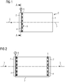
- a substantially cylindrical coil 1 of a transformer is clamped between a device according to the invention and a counter-holding element, not shown.
- the device according to the invention comprises a pressure element 2 and a hydraulic element 4 which is arranged between the pressure element 2 and a surface 9 of the spool 1 .
- the surface 9 is opposite a base 8 of the coil 1, on which base 8 the coil 1 is in engagement with the counter-holding element.
- the coil 1 in particular windings of the coil 1—is pressed between the counter-holding element and the device according to the invention.
- a pressing force is introduced via several force introduction points into the pressure element 2, which can be designed as a pressure plate or pressure ring, of the device and subsequently transmitted to the coil 1 via the hydraulic element 4 and the spacers 6.
- the pressing force has at least one component which acts on the coil 1 along an axial direction 3 of the coil 1, the The axial direction runs parallel to a longitudinal axis 5 of the coil 1 .
- FIG. 2 shows the arrangement 1 , A further device according to the invention being provided instead of the counter-holding element. This is therefore arranged on the base surface 8 of the spool 1 and also applies a pressing force to the spool 1, which acts on the spool 1 in the axial direction of the spool 1 and is thus directed in the opposite direction to the pressing force which is arranged on the surface 9 of the spool 1 Device is transferred to the coil 1.
- the amount of pressing forces transmitted via the two devices can be identical or different.
- the hydraulic elements 4 of the devices are connected to one another via a hydraulic connection 7, so that differences in the pressing forces acting on the two pressure elements 2 are compensated for due to the hydrostatic pressure equalization.
- the printing element 2 is in front of the plane of the drawing and is therefore not visible.
- the pressing force acts in each case in the axial direction 3, which is normal to the plane of the drawing and penetrates into it.
- the hydraulic element 4 of the device is formed by a single hydraulic hose. This is arranged to run spirally around the center point of the surface 9 or around the longitudinal axis 5 of the coil 1 and is provided with a single control device 10 .
- the hydraulic element 4 is formed by four concentrically arranged hydraulic hoses, which are connected to one another and to a single control device 10 via a hydraulic connection 7 .
- each of the hydraulic hoses can be subjected to a specific pressure separately.
- the hydraulic element 4 is formed by a plurality of arc-shaped hydraulic hoses and by a plurality of hydraulic cylinders.
- the individual hydraulic hoses can either be hydraulically connected to one another and provided with a common control device 10, or not connected to one another and each provided with its own control device 10; The same applies to the individual hydraulic cylinders.
- Separate hydraulic hoses and hydraulic cylinders can be applied separately with a specific pressure.
- the hydraulic element 4 is formed by a plurality of radially arranged hydraulic hoses.
- the individual hydraulic hoses are not connected to one another and are therefore each provided with their own control device 10 .
- the individual hydraulic hoses can each be separately subjected to a specific pressure.
- the embodiment variant according to 7 only a single control device 10, the individual hydraulic hoses being connected to one another via a hydraulic connection 7.
Landscapes
- Engineering & Computer Science (AREA)
- Power Engineering (AREA)
- Measuring Fluid Pressure (AREA)
- General Induction Heating (AREA)
Claims (5)
- Dispositif de compression d'un bloc ayant un ou plusieurs enroulements d'une machine électrique statique, de préférence d'une bobine (1) d'un transformateur, comprenant un élément (2) d'application d'une pression, pour transmettre une force de compression, s'appliquant au bloc, dans une direction (3) axiale du bloc, dans lequel le dispositif a au moins un élément (4) hydraulique à mettre entre l'élément (2) d'application d'une pression et le bloc, afin de régler une répartition d'une pression de compression s'appliquant au bloc,
caractérisé en ce que l'élément (4) hydraulique est constitué par au moins un tuyau souple hydraulique et le tuyau souple hydraulique est disposé, rapporté à un axe (5) longitudinal du bloc, en s'étendant en spirale. - Machine électrique statique comprenant au moins un bloc ayant un ou plusieurs enroulements, ainsi qu'au moins un dispositif suivant la revendication 1, dans laquelle le au moins un, de préférence chaque, élément (4) hydraulique est comprimé entre l'élément (2) d'application d'une pression et le bloc.
- Machine électrique statique suivant la revendication 2, caractérisée en ce qu'au moins une, de préférence plusieurs, cales (6) sont disposées entre l'élément (4) hydraulique et le bloc.
- Machine électrique statique suivant l'une des revendications 2 ou 3, dans laquelle celle-ci est constituée sous la forme d'un transformateur électrique, et dans laquelle le bloc est constitué sous la forme d'une bobine (1) du transformateur.
- Machine électrique statique suivant l'une des revendications 2 ou 3, dans laquelle celle-ci est constituée sous la forme d'un réacteur électrique, et dans laquelle le bloc est constitué sous la forme d'une bobine (1) du réacteur.
Priority Applications (1)
| Application Number | Priority Date | Filing Date | Title |
|---|---|---|---|
| EP19154693.6A EP3690902B1 (fr) | 2019-01-31 | 2019-01-31 | Dispositif de pressage d'un bloc comportant un ou une pluralité d'enroulements d'une machine électrique statique |
Applications Claiming Priority (1)
| Application Number | Priority Date | Filing Date | Title |
|---|---|---|---|
| EP19154693.6A EP3690902B1 (fr) | 2019-01-31 | 2019-01-31 | Dispositif de pressage d'un bloc comportant un ou une pluralité d'enroulements d'une machine électrique statique |
Publications (2)
| Publication Number | Publication Date |
|---|---|
| EP3690902A1 EP3690902A1 (fr) | 2020-08-05 |
| EP3690902B1 true EP3690902B1 (fr) | 2022-08-10 |
Family
ID=65275957
Family Applications (1)
| Application Number | Title | Priority Date | Filing Date |
|---|---|---|---|
| EP19154693.6A Active EP3690902B1 (fr) | 2019-01-31 | 2019-01-31 | Dispositif de pressage d'un bloc comportant un ou une pluralité d'enroulements d'une machine électrique statique |
Country Status (1)
| Country | Link |
|---|---|
| EP (1) | EP3690902B1 (fr) |
Family Cites Families (4)
| Publication number | Priority date | Publication date | Assignee | Title |
|---|---|---|---|---|
| SE386534B (sv) * | 1974-11-08 | 1976-08-09 | Asea Ab | Anordning for inspenning av transformatorlindningar pa hydraulisk veg |
| JPS5749211A (en) * | 1980-09-08 | 1982-03-23 | Mitsubishi Electric Corp | Electromagnetic induction device |
| DE3236740C2 (de) * | 1982-10-04 | 1984-08-09 | Schorch GmbH, 4050 Mönchengladbach | Vorrichtung zum Pressen von Wicklungen von Transformatoren und Drosselspulen |
| JPS59121816A (ja) * | 1982-12-27 | 1984-07-14 | Toshiba Corp | 巻線締付装置 |
-
2019
- 2019-01-31 EP EP19154693.6A patent/EP3690902B1/fr active Active
Also Published As
| Publication number | Publication date |
|---|---|
| EP3690902A1 (fr) | 2020-08-05 |
Similar Documents
| Publication | Publication Date | Title |
|---|---|---|
| EP3122999B1 (fr) | Écrou de serrage annulaire pour tirant | |
| DE19513457A1 (de) | Rotor einer elektrischen Maschine | |
| DE102010016701A1 (de) | Leiteinrichtungen zur Kühlung von Generatorspulen | |
| EP2850719B1 (fr) | Ensemble stator pour machine electrique | |
| EP2878722B1 (fr) | Procédé de commande d'appel de fil, appareil d'appel de fil et système doté d'appareils d'appel de fil | |
| DE102004046107A1 (de) | Sensor | |
| EP3690902B1 (fr) | Dispositif de pressage d'un bloc comportant un ou une pluralité d'enroulements d'une machine électrique statique | |
| EP3140552B1 (fr) | Vérin hydraulique plat, coussin de levage, son utilisation, et procédé d'alignement d'un générateur | |
| WO2023088732A1 (fr) | Machine électrique, en particulier machine électrique pour véhicule à moteur | |
| DE10310306A1 (de) | Vorrichtung zum Spannen einer Statorwicklung | |
| EP2707214A1 (fr) | Élément de codage pour l'équipement d'au moins un porte-came d'un rotor d'une presse rotative, et son procédé | |
| DE102017127771A1 (de) | Steuerung der Faserstoffbehandlung | |
| EP4483476B1 (fr) | Support de tête de bobinage d'un rotor pour une machine électrique | |
| WO2021004676A1 (fr) | Rotor pour une machine électrique | |
| DE102013111537A1 (de) | Doppelfriktionsaggregat mit verstellbaren Friktionsspindeln | |
| WO2023156370A1 (fr) | Rotor pour une machine électrique | |
| DE102017003424A1 (de) | Spritzgiessmaschine, die einen Temperaturregelungsmantel umfasst | |
| WO2010102922A1 (fr) | Dispositif de fixation axiale d'un enroulement de stator d'une machine électrique | |
| DE102010053404A1 (de) | Vorrichtung und Verfahren zur Montage von Maschinenteilen | |
| EP3714098A1 (fr) | Dispositif de broyage | |
| WO2021004675A1 (fr) | Rotor pour une machine électrique | |
| DE102015016652B3 (de) | Verfahren zum Aufbringen einer Wicklung auf einem Stator | |
| DE19637048C2 (de) | Vorrichtung zur Übertragung einer Kraft von einem ersten ring- oder zylinderförmigen Bauteil auf ein zweites Ring- oder zylinderförmiges Bauteil | |
| DE202016101016U1 (de) | Wendeeinrichtung | |
| DE102024111533A1 (de) | Kühlsystem sowie elektrische Maschine |
Legal Events
| Date | Code | Title | Description |
|---|---|---|---|
| PUAI | Public reference made under article 153(3) epc to a published international application that has entered the european phase |
Free format text: ORIGINAL CODE: 0009012 |
|
| STAA | Information on the status of an ep patent application or granted ep patent |
Free format text: STATUS: THE APPLICATION HAS BEEN PUBLISHED |
|
| AK | Designated contracting states |
Kind code of ref document: A1 Designated state(s): AL AT BE BG CH CY CZ DE DK EE ES FI FR GB GR HR HU IE IS IT LI LT LU LV MC MK MT NL NO PL PT RO RS SE SI SK SM TR |
|
| AX | Request for extension of the european patent |
Extension state: BA ME |
|
| RAP1 | Party data changed (applicant data changed or rights of an application transferred) |
Owner name: SIEMENS ENERGY GLOBAL GMBH & CO. KG |
|
| STAA | Information on the status of an ep patent application or granted ep patent |
Free format text: STATUS: REQUEST FOR EXAMINATION WAS MADE |
|
| 17P | Request for examination filed |
Effective date: 20210208 |
|
| RBV | Designated contracting states (corrected) |
Designated state(s): AL AT BE BG CH CY CZ DE DK EE ES FI FR GB GR HR HU IE IS IT LI LT LU LV MC MK MT NL NO PL PT RO RS SE SI SK SM TR |
|
| GRAP | Despatch of communication of intention to grant a patent |
Free format text: ORIGINAL CODE: EPIDOSNIGR1 |
|
| STAA | Information on the status of an ep patent application or granted ep patent |
Free format text: STATUS: GRANT OF PATENT IS INTENDED |
|
| INTG | Intention to grant announced |
Effective date: 20220321 |
|
| GRAS | Grant fee paid |
Free format text: ORIGINAL CODE: EPIDOSNIGR3 |
|
| GRAA | (expected) grant |
Free format text: ORIGINAL CODE: 0009210 |
|
| STAA | Information on the status of an ep patent application or granted ep patent |
Free format text: STATUS: THE PATENT HAS BEEN GRANTED |
|
| AK | Designated contracting states |
Kind code of ref document: B1 Designated state(s): AL AT BE BG CH CY CZ DE DK EE ES FI FR GB GR HR HU IE IS IT LI LT LU LV MC MK MT NL NO PL PT RO RS SE SI SK SM TR |
|
| REG | Reference to a national code |
Ref country code: AT Ref legal event code: REF Ref document number: 1511162 Country of ref document: AT Kind code of ref document: T Effective date: 20220815 Ref country code: CH Ref legal event code: EP |
|
| REG | Reference to a national code |
Ref country code: IE Ref legal event code: FG4D Free format text: LANGUAGE OF EP DOCUMENT: GERMAN |
|
| REG | Reference to a national code |
Ref country code: DE Ref legal event code: R096 Ref document number: 502019005199 Country of ref document: DE |
|
| REG | Reference to a national code |
Ref country code: SE Ref legal event code: TRGR |
|
| REG | Reference to a national code |
Ref country code: NL Ref legal event code: FP |
|
| REG | Reference to a national code |
Ref country code: LT Ref legal event code: MG9D |
|
| PG25 | Lapsed in a contracting state [announced via postgrant information from national office to epo] |
Ref country code: RS Free format text: LAPSE BECAUSE OF FAILURE TO SUBMIT A TRANSLATION OF THE DESCRIPTION OR TO PAY THE FEE WITHIN THE PRESCRIBED TIME-LIMIT Effective date: 20220810 Ref country code: PT Free format text: LAPSE BECAUSE OF FAILURE TO SUBMIT A TRANSLATION OF THE DESCRIPTION OR TO PAY THE FEE WITHIN THE PRESCRIBED TIME-LIMIT Effective date: 20221212 Ref country code: NO Free format text: LAPSE BECAUSE OF FAILURE TO SUBMIT A TRANSLATION OF THE DESCRIPTION OR TO PAY THE FEE WITHIN THE PRESCRIBED TIME-LIMIT Effective date: 20221110 Ref country code: LV Free format text: LAPSE BECAUSE OF FAILURE TO SUBMIT A TRANSLATION OF THE DESCRIPTION OR TO PAY THE FEE WITHIN THE PRESCRIBED TIME-LIMIT Effective date: 20220810 Ref country code: LT Free format text: LAPSE BECAUSE OF FAILURE TO SUBMIT A TRANSLATION OF THE DESCRIPTION OR TO PAY THE FEE WITHIN THE PRESCRIBED TIME-LIMIT Effective date: 20220810 Ref country code: FI Free format text: LAPSE BECAUSE OF FAILURE TO SUBMIT A TRANSLATION OF THE DESCRIPTION OR TO PAY THE FEE WITHIN THE PRESCRIBED TIME-LIMIT Effective date: 20220810 |
|
| PG25 | Lapsed in a contracting state [announced via postgrant information from national office to epo] |
Ref country code: PL Free format text: LAPSE BECAUSE OF FAILURE TO SUBMIT A TRANSLATION OF THE DESCRIPTION OR TO PAY THE FEE WITHIN THE PRESCRIBED TIME-LIMIT Effective date: 20220810 Ref country code: IS Free format text: LAPSE BECAUSE OF FAILURE TO SUBMIT A TRANSLATION OF THE DESCRIPTION OR TO PAY THE FEE WITHIN THE PRESCRIBED TIME-LIMIT Effective date: 20221210 Ref country code: HR Free format text: LAPSE BECAUSE OF FAILURE TO SUBMIT A TRANSLATION OF THE DESCRIPTION OR TO PAY THE FEE WITHIN THE PRESCRIBED TIME-LIMIT Effective date: 20220810 Ref country code: GR Free format text: LAPSE BECAUSE OF FAILURE TO SUBMIT A TRANSLATION OF THE DESCRIPTION OR TO PAY THE FEE WITHIN THE PRESCRIBED TIME-LIMIT Effective date: 20221111 |
|
| PG25 | Lapsed in a contracting state [announced via postgrant information from national office to epo] |
Ref country code: SM Free format text: LAPSE BECAUSE OF FAILURE TO SUBMIT A TRANSLATION OF THE DESCRIPTION OR TO PAY THE FEE WITHIN THE PRESCRIBED TIME-LIMIT Effective date: 20220810 Ref country code: RO Free format text: LAPSE BECAUSE OF FAILURE TO SUBMIT A TRANSLATION OF THE DESCRIPTION OR TO PAY THE FEE WITHIN THE PRESCRIBED TIME-LIMIT Effective date: 20220810 Ref country code: ES Free format text: LAPSE BECAUSE OF FAILURE TO SUBMIT A TRANSLATION OF THE DESCRIPTION OR TO PAY THE FEE WITHIN THE PRESCRIBED TIME-LIMIT Effective date: 20220810 Ref country code: DK Free format text: LAPSE BECAUSE OF FAILURE TO SUBMIT A TRANSLATION OF THE DESCRIPTION OR TO PAY THE FEE WITHIN THE PRESCRIBED TIME-LIMIT Effective date: 20220810 Ref country code: CZ Free format text: LAPSE BECAUSE OF FAILURE TO SUBMIT A TRANSLATION OF THE DESCRIPTION OR TO PAY THE FEE WITHIN THE PRESCRIBED TIME-LIMIT Effective date: 20220810 |
|
| REG | Reference to a national code |
Ref country code: DE Ref legal event code: R097 Ref document number: 502019005199 Country of ref document: DE |
|
| PG25 | Lapsed in a contracting state [announced via postgrant information from national office to epo] |
Ref country code: SK Free format text: LAPSE BECAUSE OF FAILURE TO SUBMIT A TRANSLATION OF THE DESCRIPTION OR TO PAY THE FEE WITHIN THE PRESCRIBED TIME-LIMIT Effective date: 20220810 Ref country code: EE Free format text: LAPSE BECAUSE OF FAILURE TO SUBMIT A TRANSLATION OF THE DESCRIPTION OR TO PAY THE FEE WITHIN THE PRESCRIBED TIME-LIMIT Effective date: 20220810 |
|
| PLBE | No opposition filed within time limit |
Free format text: ORIGINAL CODE: 0009261 |
|
| STAA | Information on the status of an ep patent application or granted ep patent |
Free format text: STATUS: NO OPPOSITION FILED WITHIN TIME LIMIT |
|
| PG25 | Lapsed in a contracting state [announced via postgrant information from national office to epo] |
Ref country code: AL Free format text: LAPSE BECAUSE OF FAILURE TO SUBMIT A TRANSLATION OF THE DESCRIPTION OR TO PAY THE FEE WITHIN THE PRESCRIBED TIME-LIMIT Effective date: 20220810 |
|
| 26N | No opposition filed |
Effective date: 20230511 |
|
| PG25 | Lapsed in a contracting state [announced via postgrant information from national office to epo] |
Ref country code: SI Free format text: LAPSE BECAUSE OF FAILURE TO SUBMIT A TRANSLATION OF THE DESCRIPTION OR TO PAY THE FEE WITHIN THE PRESCRIBED TIME-LIMIT Effective date: 20220810 |
|
| REG | Reference to a national code |
Ref country code: CH Ref legal event code: PL |
|
| PG25 | Lapsed in a contracting state [announced via postgrant information from national office to epo] |
Ref country code: LU Free format text: LAPSE BECAUSE OF NON-PAYMENT OF DUE FEES Effective date: 20230131 |
|
| REG | Reference to a national code |
Ref country code: BE Ref legal event code: MM Effective date: 20230131 |
|
| PG25 | Lapsed in a contracting state [announced via postgrant information from national office to epo] |
Ref country code: LI Free format text: LAPSE BECAUSE OF NON-PAYMENT OF DUE FEES Effective date: 20230131 Ref country code: CH Free format text: LAPSE BECAUSE OF NON-PAYMENT OF DUE FEES Effective date: 20230131 |
|
| PG25 | Lapsed in a contracting state [announced via postgrant information from national office to epo] |
Ref country code: BE Free format text: LAPSE BECAUSE OF NON-PAYMENT OF DUE FEES Effective date: 20230131 |
|
| PG25 | Lapsed in a contracting state [announced via postgrant information from national office to epo] |
Ref country code: IE Free format text: LAPSE BECAUSE OF NON-PAYMENT OF DUE FEES Effective date: 20230131 |
|
| PG25 | Lapsed in a contracting state [announced via postgrant information from national office to epo] |
Ref country code: IT Free format text: LAPSE BECAUSE OF FAILURE TO SUBMIT A TRANSLATION OF THE DESCRIPTION OR TO PAY THE FEE WITHIN THE PRESCRIBED TIME-LIMIT Effective date: 20220810 |
|
| PG25 | Lapsed in a contracting state [announced via postgrant information from national office to epo] |
Ref country code: MC Free format text: LAPSE BECAUSE OF FAILURE TO SUBMIT A TRANSLATION OF THE DESCRIPTION OR TO PAY THE FEE WITHIN THE PRESCRIBED TIME-LIMIT Effective date: 20220810 |
|
| PG25 | Lapsed in a contracting state [announced via postgrant information from national office to epo] |
Ref country code: MC Free format text: LAPSE BECAUSE OF FAILURE TO SUBMIT A TRANSLATION OF THE DESCRIPTION OR TO PAY THE FEE WITHIN THE PRESCRIBED TIME-LIMIT Effective date: 20220810 |
|
| PG25 | Lapsed in a contracting state [announced via postgrant information from national office to epo] |
Ref country code: BG Free format text: LAPSE BECAUSE OF FAILURE TO SUBMIT A TRANSLATION OF THE DESCRIPTION OR TO PAY THE FEE WITHIN THE PRESCRIBED TIME-LIMIT Effective date: 20220810 |
|
| PG25 | Lapsed in a contracting state [announced via postgrant information from national office to epo] |
Ref country code: BG Free format text: LAPSE BECAUSE OF FAILURE TO SUBMIT A TRANSLATION OF THE DESCRIPTION OR TO PAY THE FEE WITHIN THE PRESCRIBED TIME-LIMIT Effective date: 20220810 |
|
| REG | Reference to a national code |
Ref country code: AT Ref legal event code: MM01 Ref document number: 1511162 Country of ref document: AT Kind code of ref document: T Effective date: 20240131 |
|
| PG25 | Lapsed in a contracting state [announced via postgrant information from national office to epo] |
Ref country code: AT Free format text: LAPSE BECAUSE OF NON-PAYMENT OF DUE FEES Effective date: 20240131 |
|
| PG25 | Lapsed in a contracting state [announced via postgrant information from national office to epo] |
Ref country code: CY Free format text: LAPSE BECAUSE OF FAILURE TO SUBMIT A TRANSLATION OF THE DESCRIPTION OR TO PAY THE FEE WITHIN THE PRESCRIBED TIME-LIMIT; INVALID AB INITIO Effective date: 20190131 |
|
| PG25 | Lapsed in a contracting state [announced via postgrant information from national office to epo] |
Ref country code: HU Free format text: LAPSE BECAUSE OF FAILURE TO SUBMIT A TRANSLATION OF THE DESCRIPTION OR TO PAY THE FEE WITHIN THE PRESCRIBED TIME-LIMIT; INVALID AB INITIO Effective date: 20190131 |
|
| PG25 | Lapsed in a contracting state [announced via postgrant information from national office to epo] |
Ref country code: TR Free format text: LAPSE BECAUSE OF FAILURE TO SUBMIT A TRANSLATION OF THE DESCRIPTION OR TO PAY THE FEE WITHIN THE PRESCRIBED TIME-LIMIT Effective date: 20220810 |
|
| PGFP | Annual fee paid to national office [announced via postgrant information from national office to epo] |
Ref country code: NL Payment date: 20260122 Year of fee payment: 8 |
|
| PGFP | Annual fee paid to national office [announced via postgrant information from national office to epo] |
Ref country code: SE Payment date: 20260126 Year of fee payment: 8 |
|
| PGFP | Annual fee paid to national office [announced via postgrant information from national office to epo] |
Ref country code: GB Payment date: 20260126 Year of fee payment: 8 |
|
| PGFP | Annual fee paid to national office [announced via postgrant information from national office to epo] |
Ref country code: DE Payment date: 20260127 Year of fee payment: 8 |
|
| PGFP | Annual fee paid to national office [announced via postgrant information from national office to epo] |
Ref country code: AT Payment date: 20260410 Year of fee payment: 5 |
|
| PGFP | Annual fee paid to national office [announced via postgrant information from national office to epo] |
Ref country code: FR Payment date: 20260126 Year of fee payment: 8 |