EP3692889A1 - Dispositif d'examen de la vue - Google Patents
Dispositif d'examen de la vue Download PDFInfo
- Publication number
- EP3692889A1 EP3692889A1 EP18864830.7A EP18864830A EP3692889A1 EP 3692889 A1 EP3692889 A1 EP 3692889A1 EP 18864830 A EP18864830 A EP 18864830A EP 3692889 A1 EP3692889 A1 EP 3692889A1
- Authority
- EP
- European Patent Office
- Prior art keywords
- subject
- retina
- invisible
- visible
- examination
- Prior art date
- Legal status (The legal status is an assumption and is not a legal conclusion. Google has not performed a legal analysis and makes no representation as to the accuracy of the status listed.)
- Granted
Links
Images





Classifications
-
- A—HUMAN NECESSITIES
- A61—MEDICAL OR VETERINARY SCIENCE; HYGIENE
- A61B—DIAGNOSIS; SURGERY; IDENTIFICATION
- A61B3/00—Apparatus for testing the eyes; Instruments for examining the eyes
- A61B3/10—Objective types, i.e. instruments for examining the eyes independent of the patients' perceptions or reactions
- A61B3/12—Objective types, i.e. instruments for examining the eyes independent of the patients' perceptions or reactions for looking at the eye fundus, e.g. ophthalmoscopes
- A61B3/1225—Objective types, i.e. instruments for examining the eyes independent of the patients' perceptions or reactions for looking at the eye fundus, e.g. ophthalmoscopes using coherent radiation
-
- A—HUMAN NECESSITIES
- A61—MEDICAL OR VETERINARY SCIENCE; HYGIENE
- A61B—DIAGNOSIS; SURGERY; IDENTIFICATION
- A61B3/00—Apparatus for testing the eyes; Instruments for examining the eyes
- A61B3/10—Objective types, i.e. instruments for examining the eyes independent of the patients' perceptions or reactions
- A61B3/1025—Objective types, i.e. instruments for examining the eyes independent of the patients' perceptions or reactions for confocal scanning
-
- A—HUMAN NECESSITIES
- A61—MEDICAL OR VETERINARY SCIENCE; HYGIENE
- A61B—DIAGNOSIS; SURGERY; IDENTIFICATION
- A61B3/00—Apparatus for testing the eyes; Instruments for examining the eyes
- A61B3/0016—Operational features thereof
- A61B3/0025—Operational features thereof characterised by electronic signal processing, e.g. eye models
-
- A—HUMAN NECESSITIES
- A61—MEDICAL OR VETERINARY SCIENCE; HYGIENE
- A61B—DIAGNOSIS; SURGERY; IDENTIFICATION
- A61B3/00—Apparatus for testing the eyes; Instruments for examining the eyes
- A61B3/0016—Operational features thereof
- A61B3/0041—Operational features thereof characterised by display arrangements
- A61B3/0058—Operational features thereof characterised by display arrangements for multiple images
-
- A—HUMAN NECESSITIES
- A61—MEDICAL OR VETERINARY SCIENCE; HYGIENE
- A61B—DIAGNOSIS; SURGERY; IDENTIFICATION
- A61B3/00—Apparatus for testing the eyes; Instruments for examining the eyes
- A61B3/0091—Fixation targets for viewing direction
-
- A—HUMAN NECESSITIES
- A61—MEDICAL OR VETERINARY SCIENCE; HYGIENE
- A61B—DIAGNOSIS; SURGERY; IDENTIFICATION
- A61B3/00—Apparatus for testing the eyes; Instruments for examining the eyes
- A61B3/02—Subjective types, i.e. testing apparatus requiring the active assistance of the patient
- A61B3/024—Subjective types, i.e. testing apparatus requiring the active assistance of the patient for determining the visual field, e.g. perimeter types
Definitions
- the present invention relates to a visual sense examination device.
- Patent Document 1 Japanese Patent Application Publication No. 2007-181537
- the present invention has been made in view of the above problem, and aims to provide a visual sense examination device that can project a high-resolution image.
- the present invention is a visual sense examination device including: a beam source that emits a visible beam and an invisible beam; an image projection optical system that includes a first scanning unit oscillating at a first frequency to two-dimensionally scan the visible beam, and that emits the visible beam to a retina of a subject to project an image on the retina of the subject; an invisible beam optical system that includes a second scanning unit oscillating at a second frequency different from the first frequency, to two-dimensionally scan the invisible beam, and that emits the invisible beam to the retina of the subject; a detector that detects the invisible beam reflected by the retina of the subject; and a control unit that controls the emission of the visible beam and the invisible beam from the beam source, and detects a state of a fundus of the subject from an output signal of the detector.
- the visual sense examination device may include a spectral unit that emits, in a first direction, the visible beam emitted from the beam source, and emits the invisible beam in a second direction different from the first direction.
- Optical axes of the image projection optical system and the invisible beam optical system may match.
- the image projection optical system may two-dimensionally scan the visible beam emitted in the first direction to emit the visible beam to the retina of the subject
- the invisible beam optical system may two-dimensionally scan the invisible beam emitted in the second direction to emit the invisible beam to the retina of the subject.
- the spectral unit may be a dichroic mirror that transmits one of the visible beam and the invisible beam, and reflects the other thereof.
- the visual sense examination device may include a synthesis unit that synthesizes the visible beam scanned by the first scanning unit and the invisible beam scanned by the second scanning unit.
- the invisible beam may be an infrared beam
- the control unit may generate a fundus image of an eye of the subject based on the output signal of the detector.
- control unit may control the emission of the visible beam from the beam source to project, on the retina of the subject, a fixation visual target for directing a visual line of the subject, and cause the beam source to emit the invisible beam and irradiate the retina of the subject with the invisible beam.
- control unit may control the emission of the visible beam from the beam source to project an examination visual target for examining an eye of the subject on the retina of the subject.
- control unit may control the emission of the visible beam from the beam source to project an examination visual target for examining an eye of the subject on the retina of the subject, and cause the beam source to emit the invisible beam and irradiate the retina of the subject with the invisible beam, the projection of the examination visual target and the irradiation of the invisible beam being performed in parallel.
- control unit may control the emission of the visible beam from the beam source to project an examination visual target for examining an eye of the subject on the retina of the subject, and generate a third examination image in which a first examination image generated based on the output signal of the detector and a second examination image generated based on an input response in accordance with the examination visual target of the subject are superimposed.
- the first examination image may be a fundus image
- the second examination image may be an image related to visual field defect
- the present invention is a visual sense examination device including: a beam source that emits a visible beam and an invisible beam; an image projection optical system that includes a first scanning unit oscillating at a first frequency to two-dimensionally scan the visible beam, and that emits the visible beam to a retina of a subject to project an image on the retina of the subject; an invisible beam optical system that includes a second scanning unit oscillating at a second frequency different from the first frequency, to two-dimensionally scan the invisible beam, and that emits the invisible beam to the retina of the subject; a detector that detects the visible beam and the invisible beam reflected by the retina of the subject; and a control unit that controls the emission of the visible beam and the invisible beam from the beam source, detects a first state of a fundus of the subject from an output signal of the detector based on the visible beam, and detects a second state of the fundus of the subject from an output signal of the detector based on the invisible beam.
- control unit may control the emission of the visible beam from the beam source to project at least one of a fixation visual target for directing a visual line of the subject and an examination visual target for examining an eye of the subject on the retina of the subject.
- control unit may generate a fundus image of an eye of the subject as the detection of the first state of the fundus and the second state of the fundus.
- the present invention is a visual sense examination device including: a visible beam source that emits a visible beam; an invisible beam source that emits an invisible beam; a beam source beam synthesis unit that synthesizes the visible beam and the invisible beam to generate a synthesis beam; a scanning unit that two-dimensionally scan the visible beam and the invisible beam; an emission optical system that emits the visible beam to a retina of a subject to project an image on the retina of the subject, and emits the invisible beam to the retina of the subject; a detector that detects the invisible beam reflected by the retina of the subject; and a control unit that controls the emission of the visible beam from the visible beam source and the invisible beam from the invisible beam source, and detects a state of a fundus of the subject from an output signal of the detector.
- the invisible beam may be an infrared beam
- the control unit may generate a fundus image of an eye of the subject based on the output signal of the detector.
- control unit may control the emission of the visible beam from the visible beam source to project, on the retina of the subject, a fixation visual target for directing a visual line of the subject, and cause the invisible beam source to emit the invisible beam and irradiate the retina of the subject with the invisible beam.
- control unit may control the emission of the visible beam from the visible beam source to project an examination visual target for examining an eye of the subject on the retina of the subject.
- control unit may control the emission of the visible beam from the visible beam source to project an examination visual target for examining an eye of the subject on the retina of the subject, and generate a third examination image in which a first examination image generated based on the output signal of the detector and a second examination image generated based on an input response in accordance with the examination visual target of the subject are superimposed.
- the first examination image may be a fundus image
- the second examination image may be an image related to visual field defect
- FIG. 15 is a diagram illustrating an optical system of the visual sense examination device according to the fourth embodiment.
- FIG. 1 is a block diagram of a visual sense examination device according to a first embodiment.
- a visual sense examination device 100 includes a projection unit 10, a control unit 30, a detector 40 and a display unit 41.
- the projection unit 10 includes a beam source 11, an adjustment unit 12, a spectral unit 13, an image projection optical system 14, an infrared beam optical system 15, a driving circuit 16 and an input circuit 17.
- the image projection optical system 14 has a scanning unit 20, and the infrared beam optical system 15 has a scanning unit 22.
- the scanning units 20 and 22 are scanning mirrors such as MEMS (Micro Electro Mechanical System) mirrors, or transmission type scanners, for example.
- the control unit 30 includes a driving control unit 31, a signal processing unit 32 and an image generation unit 33.
- the driving control unit 31 generates an image to be projected on a retina or the like.
- An image signal is input from the driving control unit 31 to the input circuit 17.
- the driving circuit 16 drives the beam source 11 and the scanning units 20 and 22 based on the image signal obtained by the input circuit 17 and a control signal of the driving control unit 31.
- the beam source 11 emits a visible beam such as a red laser beam (wavelength: about 610 nm to 660 nm), a green laser beam (wavelength: about 515 nm to 540 nm) and a blue laser beam (wavelength: about 440 nm to 480 nm), and an invisible beam which is an infrared laser beam (wavelength: about 850 nm), for example. That is, the beam source 11 has respective laser diode chips for the red laser beam, the green laser beam, the blue laser beam and the infrared laser beam in a single module.
- the beam source 11 may emit a laser beam with a single wavelength as the visible beam.
- the adjustment unit 12 has a collimate lens, a toric lens, and/or an aperture, and shapes a laser beam 50 emitted from the beam source 11.
- the laser beam 50 is a beam obtained by synthesizing the red laser beam, the green laser beam, a blue laser beam and/or the infrared laser beam, and the optical axes of the respective laser beams match each other.
- the spectral unit 13 is a dichroic mirror, for example, and spectrally disperses the laser beam 50 into a visible laser beam 50a including the red laser beam, the green laser beam and the blue laser beam, and an infrared laser beam 50b.
- the image projection optical system 14 two-dimensionally scans the visible laser beam 50a spectrally dispersed by the spectral unit 13 with the scanning unit 20 and emits the visible laser beam 50a to an eye 70 of a subject.
- the infrared beam optical system 15 two-dimensionally scans the infrared laser beam 50b spectrally dispersed by the spectral unit 13 with the scanning unit 22 and emits the infrared laser beam 50b to the eye 70 of the subject.
- the infrared beam optical system 15 realizes a part of functions of a conventional scanning laser ophthalmoscope (SLO), for example.
- SLO scanning laser ophthalmoscope
- the detector 40 is a photodetector such as an avalanche photodiode, for example, and detects the infrared laser beam 50b reflected by the eye 70 of the subject.
- the signal processing unit 32 processes an output signal of the detector 40 based on a control signal from the driving control unit 31.
- the image generation unit 33 generates a two-dimensional image based on the signal processed by the signal processing unit 32.
- the display unit 41 is a liquid crystal display, for example, and displays the image generated by the image generation unit 33.
- the detector 40 and the signal processing unit 32 start the detection at the timing when the beam source 11 emits the infrared laser beam 50b, based on a synchronization signal from the driving circuit 16.
- the driving control unit 31, the signal processing unit 32 and the image generation unit 33 may be a processor such as a CPU (Central Processing Unit) that performs processing in cooperation with a program.
- the driving control unit 31, the signal processing unit 32 and the image generation unit 33 may be circuits designed exclusively.
- the driving control unit 31, the signal processing unit 32 and the image generation unit 33 may be a single circuit or different circuits.
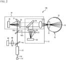
- FIG. 2 is a diagram illustrating an optical system of the visual sense examination device according to the first embodiment.
- the visual sense examination device 100 according to the first embodiment emits the laser beam to the retina 74 of the subject using Maxwellian view.
- a numerical aperture (NA) and/or a beam diameter of the laser beam 50 emitted from the beam source 11 are adjusted by the adjustment unit 12.
- the laser beam 50 are spectrally dispersed into the visible laser beam 50a including the red laser beam, the green laser beam and the blue laser beam, and the infrared laser beam 50b in the spectral unit 13.
- the spectral unit 13 is the dichroic mirror that transmits the visible laser beam 50a and reflects the infrared laser beam 50b, for example.
- the spectral unit 13 is not limited to the dichroic mirror, but may be another optical element such as a dichroic prism.
- the visible laser beam 50a is reflected by a plane mirror 21 and is scanned two-dimensionally by the scanning unit 20.
- the scanned visible laser beam 50a is emitted to the eye 70 of the subject via a lens 25, a synthesis unit 26 and a lens 27.
- the visible laser beam 50a converges near a crystalline lens 72, passes through a vitreous body 76, and is emitted to the retina 74. Thereby, the image is projected on the retina 74.
- the scanning unit 20 oscillates at a relatively high frequency such as 28 kHz so that the images of 60 frames are projected per second, for example.
- the infrared laser beam 50b is reflected by a plane mirror 23 and is scanned two-dimensionally by the scanning unit 22.
- the scanned infrared laser beam 50b is emitted to the eye 70 of the subject via the lens 25, the synthesis unit 26 and the lens 27.
- the infrared laser beam 50b converges near the crystalline lens 72, passes through the vitreous body 76, and is emitted to the retina 74.
- the infrared laser beam 50b is reflected by the retina 74.
- the reflected infrared laser beam 50b returns along an optical path where the infrared laser beam 50b has advanced toward the retina 74.
- the reflected infrared laser beam 50b returns in an order of the lens 27, the synthesis unit 26, a lens 24, the scanning unit 22, the plane mirror 23 and the spectral unit 13, along the optical path where the infrared laser beam 50b has advanced toward the retina 74. Then, the reflected infrared laser beam 50b enters the detector 40 via a half mirror 43 and a lens 44. Thereby, the detector 40 detects the infrared laser beam 50b reflected by the retina 74.
- the state of a fundus of the eye 70 can be detected (state information of the fundus can be obtained) based on the detection result of the luminance change of the infrared laser beam 50b by the detector 40, and a fundus image can be obtained as an example of a detection object.
- the scanning unit 22 oscillates at a relatively low frequency such as 12.5 kHz, which corresponds to a case where the images of 25 frames are projected per second, so that the detection of the state of the fundus of the eye 70 can be realized by the infrared laser beam 50b.
- FIGs. 3A and 3B are diagrams illustrating the scanning of the visible laser beam 50a and the infrared laser beam 50b.
- the image 60 is projected on the retina 74 by the visible laser beam 50a.
- the scanning unit 20 of the image projection optical system 14 performs a raster scan of the visible laser beam 50a from an upper left to a lower right, as indicated by arrows 61. If the beam source 11 does not emit the visible laser beam 50a even when the scanning unit 20 oscillates, the visible laser beam 50a is not emitted to the retina 74.
- the visible laser beam 50a is not emitted at dashed arrows 61 of FIG. 3A .
- the driving circuit 16 synchronizes the emission of the visible laser beam 50a from the beam source 11 with the oscillation of the scanning unit 20. Thereby, the beam source 11 emits the visible laser beam 50a along thick solid lines 62. Accordingly, a fixation visual target 63 for directing a visual line of the subject is projected on a central region of the retina 74, for example.
- the fixation visual target 63 is not limited to a cross pattern, but may be other figure such as a dot pattern, a star pattern, a circular pattern or a polygonal pattern as long as the visual line of the subject can be directed. Also, a display position of the fixation visual target 63 is not limited to the central region of the retina 74, but may be changed as needed.
- the scanning unit 22 of the infrared beam optical system 15 performs a raster scan of the infrared laser beam 50b from the upper left to the lower right, as indicated by arrows 64. If the beam source 11 does not emit the infrared laser beam 50b even when the scanning unit 22 oscillates, the infrared laser beam 50b is not emitted to the retina 74.
- the driving circuit 16 synchronizes the emission of the infrared laser beam 50b from the beam source 11 with the oscillation of the scanning unit 22.
- the beam source 11 emits the infrared laser beam 50b in accordance with the oscillation of the scanning unit 22 in substantially the same range as the image 60, for example.
- a scanning angle of the visible laser beam 50a by the scanning unit 20 and a scanning angle of the infrared laser beam 50b by the scanning unit 22 are approximately the same size, for example.
- the synthesis unit 26 is the dichroic mirror, for example, and synthesizes the visible laser beam 50a scanned by the scanning unit 20 and the infrared laser beam 50b scanned by the scanning unit 22. After the visible laser beam 50a and the infrared laser beam 50b are synthesized by the synthesis unit 26, the optical axes thereof match each other.
- the synthesis unit 26 is not limited to the dichroic mirror, but may be another optical element such as the dichroic prism.
- the image projection optical system 14 includes the scanning unit 20, the plane mirror 21, the lens 25, the synthesis unit 26 and the lens 27.
- the infrared beam optical system 15 includes the scanning unit 22, the plane mirror 23, the lens 24, the synthesis unit 26 and the lens 27.
- the synthesis unit 26 and the lens 27 are common components in the image projection optical system 14 and the infrared beam optical system 15.
- FIG. 4 is a flowchart illustrating processing according to the first embodiment.
- the driving control unit 31 generates an image 60 as illustrated in FIG. 3A , causes the projection unit 10 to project the generated image 60 and project the fixation visual target 63 on the retina 74 (step S10).
- the driving control unit 31 causes the projection unit 10 to emit the infrared laser beam 50b to the retina 74, as illustrated in FIG. 3B (step S12).
- the signal processing unit 32 acquires an output signal of the detector 40 (step S14).
- the detector 40 detects the infrared laser beam 50b in synchronization with the synchronization signal from the driving circuit 16. That is, the detector 40 detects the infrared laser beam 50b in synchronization with the emission of the infrared laser beam 50b from the beam source 11.
- the signal processing unit 32 starts acquiring the output signal of the detector 40 in synchronization with the emission of the infrared laser beam 50b.
- the driving control unit 31 determines whether the emission of the infrared laser beam 50b corresponding to a predetermined number of frames has completed (step S16).
- the predetermined number of frames may be one frame or a plurality of frames such as 5 frames or 10 frames.
- the number of frames suitable for detecting the state of the fundus of the eye 70 by emitting the infrared laser beam 50b to the retina 74 may be appropriately selected.
- step S16: No When the emission of the infrared laser beam 50b corresponding to the predetermined number of frames has not completed (step S16: No), steps S12 and S14 are repeatedly performed.
- step S16: Yes When the emission of the infrared laser beam 50b corresponding to the predetermined number of frames has completed (step S16: Yes), the driving control unit 31 causes the projection unit 10 to finish the projection of the fixation visual target 63 (step S18).
- the image generation unit 33 generates an examination image (for example, a fundus image) of the eye 70 based on the output signal of the detector 40 acquired by the signal processing unit 32 (step S20).
- the image generation unit 33 may generate the examination image by calculating an average value of output signals from the detector 40 in the respective frames, or may generate the examination image based on a maximum value of the output signals.
- the display unit 41 displays the examination image (step S22). A doctor carefully examines the examination image indicating the state of the fundus displayed on the display unit 41 to examine a visual sense of the subject. An undulating tumor, a pseudo three-dimensional image using a phase difference, the opacity of the vitreous body or the like may be detected as the detection of the state of the fundus.
- FIG. 5 is an example of the fundus image generated by the image generation unit.
- a reference numeral 80 denotes a fovea
- a reference numeral 81 denotes an optic disk
- reference numerals 82 denote retinal arteries or retinal veins. Lesions 83 are indicated by cross-hatching portions.
- the infrared laser beam 50b is emitted to the retina 74 as illustrated in FIG. 4 .
- the image can be projected on the retina 74 in addition to emitting to the retina 74 the infrared laser beam 50b for acquiring the examination image indicating the state of the fundus of the eye 70.
- a liquid crystal display is used to project the image, it is difficult to project a high-resolution image at a predetermined position of the retina 74.
- the scanning unit 20 emits the visible laser beam 50a scanned two-dimensionally to the retina 74 to project the image on the retina 74, as illustrated in FIGs. 1 and 2 . Thereby, it is possible to project the high-resolution image.
- the scanning unit 20 scanning the visible laser beam 50a oscillates at about 28 kHz so that the images of 60 frames are projected per second, for example.
- the scanning unit 22 when the scanning unit 22 emits the infrared laser beam 50b scanned two-dimensionally to the retina 74 and the state of the fundus of the subject is detected from the output signal of the detector 40 detecting a reflected beam from the retina 74, it is desired that the scanning unit 22 oscillates at about 12.5 kHz which corresponds to a case where the images of 25 frames are projected per second, for example. This is due to the convenience of the processing such as an accuracy when the infrared laser beam 50b is used. In the first embodiment, since the scanning unit 20 scanning the visible laser beam 50a and the scanning unit 22 scanning the infrared laser beam 50b are separately provided, they can oscillate at different frequencies, to thereby achieve the above-described desire.
- the scanning unit 20 emits the visible laser beam 50a scanned two-dimensionally to the retina 74 to project the image on the retina 74, the size of the examination device can be reduced, as compared with the case where the image is projected using the liquid crystal display. It is preferable that the scanning units 20 and 22 are two-axis MEMS mirrors from the viewpoint of reducing the size, the weight and the cost of the examination device.
- the spectral unit 13 that emits the visible laser beam 50a emitted from the beam source 11 in a first direction and emits the infrared laser beam 50b in a second direction different from the first direction, as illustrated in FIG. 2 .
- the optical axes of the image projection optical system 14 and the infrared beam optical system 15 match each other, the image projection optical system 14 two-dimensionally scans the visible laser beam 50a emitted in the first direction by the spectral unit 13 to emit the visible laser beam 50a to the retina 74, and the infrared beam optical system 15 two-dimensionally scans the infrared laser beam 50b emitted in the second direction by the spectral unit 13 to emit the infrared laser beam 50b to the retina 74. Accordingly, the optical system from the beam source 11 to the spectral unit 13 can be shared by the visible laser beam 50a and the infrared laser beam 50b, so that the number of components can be reduced and the size of the examination device can be reduced.
- the spectral unit 13 is preferably the dichroic mirror that transmits the visible laser beam 50a and reflects the infrared laser beam 50b.
- the spectral unit 13 may be the dichroic mirror that reflects the visible laser beam 50a and transmits the infrared laser beam 50b. Even in this case, the examination device can be downsized.
- the synthesis unit 26 that synthesizes the visible laser beam 50a scanned by the scanning unit 20 and the infrared laser beam 50b scanned by the scanning unit 22, as illustrated in FIG. 2 . This makes it easily possible to match the optical axes of the visible laser beam 50a and the infrared laser beam 50b and project their laser beams on the retina 74.
- FIG. 6 is a block diagram of a visual sense examination device according to a second embodiment.
- a visual sense examination device 200 according to the second embodiment further includes an input unit 42, as compared with the visual sense examination device 100 according to the first embodiment.
- the input unit 42 is a device to which the subject inputs results and the like, and is a button, a touch panel, a keyboard and/or a mouse, for example.
- the signal processing unit 32 processes the output signal of the detector 40 and an output signal of the input unit 42 based on the control signal from the driving control unit 31.
- the detector 40 and the signal processing unit 32 start the detection at the timing when the beam source 11 emits the visible laser beam 50a and the infrared laser beam 50b, based on the synchronization signal from the driving circuit 16. Since other configurations are the same as those in FIG. 1 of the first embodiment, the description thereof is omitted. Since the optical systems of the visual sense examination device 200 according to the second embodiment are the same as those in FIG. 1 of the first embodiment, the illustration and the description thereof are omitted.
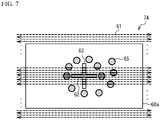
- FIG. 7 is an example of the image projected on the retina according to the second embodiment.
- an image 60a as illustrated in FIG. 7 is projected on the retina 74. That is, examination visual targets 65 for examining the eye 70 are projected in addition to the fixation visual target 63 projected on the central region of the retina 74.
- the examination visual targets 65 are projected on different regions of the retina 74 at different timings, but FIG. 7 illustrates all the examination visual targets 65 to be projected on the retina 74 for convenience.
- the examination visual target 65 is a stimulating beam emitted to a region with a predetermined size, for example.
- the shape of the examination visual target 65 is a circle as an example, the shape may be an ellipse or a polygon such as a square.
- the examination visual target 65 may be a white beam including the red, green and blue laser beams, or may be a monochromatic beam including a laser beam with a single wavelength.
- the diameter of the examination visual target 65 is about several micrometers, for example.
- FIG. 8 is a flowchart illustrating processing according to the second embodiment.
- the control unit 30 projects an image 60a as illustrated in FIG. 7 on the retina 74, and performs the examination using the examination visual target 65 (step S30).
- FIG. 9 is a flowchart illustrating a method of the examination (step S30 of FIG. 8 ) using the examination visual target according to the second embodiment.
- FIGs. 10A to 10D are diagrams illustrating the examination using the examination visual target.
- the driving control unit 31 generates the image 60a as illustrated in FIG. 7 , causes the projection unit 10 to project the generated image 60a and further project the fixation visual target 63 and the examination visual target 65 on the retina 74 (step S50).
- the examination visual targets 65 are projected on the different regions of the retina 74 at different timings. Therefore, an examination visual target 65a among the examination visual targets 65 to be projected on the different regions of the retina 74 is projected as illustrated in FIG. 10A .
- the signal processing unit 32 acquires the output signal of the input unit 42 (step S52).
- the subject operates the input unit 42 when recognizing that the examination visual target 65a is projected on the retina 74.
- the output signal is output from the input unit 42 to the signal processing unit 32.
- the signal processing unit 32 starts acquiring the output signal of the input unit 42 in synchronization with the emission of the visible laser beam 50a.
- step S54 determines whether the projection of all the examination visual targets 65 on the retina 74 has completed.
- the determination in step S54 is denied (step S54: No), and steps S50 and S52 are repeatedly performed.
- steps S50 and S52 are repeatedly performed, for example, the examination visual target 65a of FIG. 10A is projected and several seconds elapse, an examination visual target 65b is then projected on another region of the retina 74 as illustrated in FIG. 10B and several seconds further elapse, and then an examination visual target 65c is projected on still another region of the retina 74 as illustrated in FIG. 10C . This is repeatedly performed, and a final examination visual target 65z is projected on the retina 74, as illustrated in FIG. 10D .
- step S54 Yes
- the examination using the examination visual targets 65 completes. Thereby, the examination for the visual field defect can be performed, for example.
- control unit 30 detects the state of the fundus using the infrared laser beam 50b (step S32). In the detection of the state of the fundus using the infrared laser beam 50b, the processing of steps S10 to S18 in FIG. 4 is performed.
- the image generation unit 33 generates the visual field defect image based on the output signal of the input unit 42 obtained by the signal processing unit 32 in the examination using the examination visual target 65.
- the image generation unit 33 generates a fundus image based on the output signal of the detector 40 obtained by the signal processing unit 32 by emitting the infrared laser beam 50b (in the examination using the infrared laser beam 50b).
- the image generation unit 33 generates the superimposed image in which the visual field defect image and the fundus image are superimposed (step S34).
- the display unit 41 displays the superimposed image (step S36). The doctor carefully examines the examination image displayed in a superimposed fashion on the display unit 41 to examine the visual sense of the subj ect.
- FIGs. 11A to 11C are examples of the fundus image, the visual field defect image and the superimposed image generated by the image generation unit.
- FIG. 11A illustrates the fundus image.
- the reference numeral 80 denotes the fovea
- the reference numeral 81 denotes the optic disk
- the reference numerals 82 denote the retinal arteries or retinal veins.
- the lesions 83 are indicated by the cross-hatching portions.
- FIG. 11B illustrates the visual field defect image. Dotted lines indicate parts 66 where the subject has not input a response to the input unit 42 even though the examination visual target 65 has been projected on the retina 74.
- FIG. 11C illustrates the superimposed image in which the fundus image and the visual field defect image are superimposed.
- the control unit 30 controls the emission of the visible laser beam 50a from the beam source 11 and projects the examination visual target 65 for examining the eye 70 on the retina 74 of the subject.
- the examination of the eye 70 can be performed using the visible laser beam 50a in addition to detecting the state of the fundus of the eye 70 using the infrared laser beam 50b.
- FIG. 8 illustrates that the examination using the infrared laser beam 50b is performed after the examination using the examination visual target 65 is performed.
- the examination visual target 65 may be performed after the examination using the infrared laser beam 50b is performed.
- the visible laser beam 50a is emitted from the beam source 11 and the scanning unit 20 is driven, and the infrared laser beam 50b does not have to be emitted from the beam source 11 and the scanning unit 22 does not have to be driven.
- the infrared laser beam 50b When the examination using the infrared laser beam 50b is performed, the infrared laser beam 50b is emitted from the beam source 11 and the scanning unit 22 is driven, and the visible laser beam 50a does not have to be emitted from the beam source 11 and the scanning unit 20 does not have to be driven. Also, the examination using the examination visual target 65 and the examination using the infrared laser beam 50b may be performed in parallel. That is, the control unit 30 may simultaneously perform the projection of the examination visual target 65 and the emission of the infrared laser beam 50b in parallel. Thereby, the examination time can be reduced.
- the control unit 30 generates the superimposed image in which the examination image (the fundus image) generated based on the output signal of the detector 40 and the examination image (the image related to the visual field defect) generated based on the output signal of the input unit 42 are superimposed, as illustrated in FIG. 11C .
- This makes it possible to evaluate the relationship between the lesion in the examination image of the examination using the visible laser beam 50a and the lesion in the examination image of the examination using the infrared laser beam 50b. Further, this makes it possible to contribute to early detection of onset of diabetes, early detection of glaucoma, and/or early detection of age-related macular degeneration.
- PRL Preferred Retinal Locus: another retinal region that captures a visual object instead of the retinal fovea due to the reduction of the sensitivity of the retinal fovea
- PRL Preferred Retinal Locus: another retinal region that captures a visual object instead of the retinal fovea due to the reduction of the sensitivity of the retinal fovea
- FIGs. 12A and 12B are other examples of images projected on the retina according to the second embodiment.
- an image 60b having an examination visual target 67 for examining retinal visual acuity may be projected on the retina 74. That is, an image of an examination result of the retinal visual acuity may be generated based on the output signal of the input unit 42.
- FIG. 12A and 12B an image 60b having an examination visual target 67 for examining retinal visual acuity may be projected on the retina 74. That is, an image of an examination result of the retinal visual acuity may be generated based on the output signal of the input unit 42.
- the examination visual target 67 is projected at the center of the image 60b, and a plurality of dot patterns are projected as the fixation visual target 63 so as to surround the examination visual target 67.
- the fixation visual target 63 is projected on the center of the retina 74.
- the fixation visual target 63 is projected at the center of the image 60b, and the examination visual targets 67 are projected around the fixation visual target 63.
- the examination visual targets 67 are projected on different regions of the retina 74 at different timings, but FIG. 12B illustrates all the examination visual targets 67 to be projected on the retina 74 for convenience.
- the examination visual target 67 is projected at a desired position of the retina 74.
- the fixation visual target 63 is also projected and the eye of the subject is fixated on the fixation visual target 63, which makes it possible to project the examination visual target 67 at the desired position of the retina 74.
- the examination visual target 67 is not limited to the Landolt ring, but may be other marks such as characters.
- the image projection optical system 14 projects the fixation visual target 63 and the infrared beam optical system 15 emits the infrared laser beam 50b to the retina 74, so that the control unit 30 can acquire the image in which the fixation visual target 63 is displayed on the examination image of the eye 70 by the infrared laser beam 50b.
- the control unit 30 can acquire the image in which the fixation visual target 63 is displayed on the examination image of the eye 70 by the infrared laser beam 50b.
- the first and the second embodiments illustrated a case where the image projection optical system 14 projects the image such as the visual target, and the infrared beam optical system 15 detects the state of the fundus of the eye 70 of the subject with the infrared laser beam 50b emitted to the retina 74.
- the image projection optical system 14 also detects the state of the fundus of the eye 70 of the subject with the visible laser beam 50a emitted to the retina 74.
- the visual sense examination device of the third embodiment differs from that of the first embodiment in that the detector 40 is a photodetector capable of detecting the visible beam and the infrared beam. Therefore, in the third embodiment, the image projection optical system 14 emits the visible laser beam 50a to the retina 74, and the detector 40 can detect the visible laser beam 50a reflected by the retina 74.
- the visible laser beam 50a reflected by the retina 74 returns in an order of the lens 27, the synthesis unit 26, the lens 25, the scanning unit 20, the plane mirror 21 and the spectral unit 13, along the optical path where the visible laser beam 50a has advanced toward the retina 74. Then, the visible laser beam 50a enters the detector 40 via the half mirror 43 and the lens 44.
- FIG. 13 is a flowchart illustrating processing according to the third embodiment.
- the driving control unit 31 causes the projection unit 10 to emit the visible laser beam 50a to the retina 74 (step S60).
- the signal processing unit 32 acquires the output signal of the detector 40 (step S62).
- the detector 40 detects the visible laser beam 50a in synchronization with the synchronization signal from the driving circuit 16. That is, the detector 40 detects the visible laser beam 50a in synchronization with the emission of the visible laser beam 50a from the beam source 11.
- the signal processing unit 32 starts acquiring the output signal of the detector 40 in synchronization with the emission of the visible laser beam 50a.
- the driving control unit 31 causes the projection unit 10 to emit the infrared laser beam 50b to the retina 74 instead of the visible laser beam 50a (step S64).
- the signal processing unit 32 acquires the output signal of the detector 40 (step S66).
- the detector 40 detects the infrared laser beam 50b in synchronization with the synchronization signal from the driving circuit 16. That is, the detector 40 detects the infrared laser beam 50b in synchronization with the emission of the infrared laser beam 50b from the beam source 11.
- the signal processing unit 32 starts acquiring the output signal of the detector 40 in synchronization with the emission of the infrared laser beam 50b.
- the driving control unit 31 determines whether the emission of the visible laser beam 50a and the infrared laser beam 50b corresponding to a predetermined number of frames has completed (step S68).
- the predetermined number of frames may be one frame or the plurality of frames such as 5 frames or 10 frames.
- steps S60 to S66 are repeatedly performed.
- the image generation unit 33 When the emission corresponding to the predetermined number of frames has completed (step S68: Yes), the image generation unit 33 generates the examination images of the eye 70 based on the output signal of the detector 40 acquired by the signal processing unit 32 (step S70). For example, the image generation unit 33 may generate a first examination image (a first fundus image) based on the output signal of the detector 40 corresponding to the visible laser beam 50a reflected by the retina 74, and generate a second examination image (a second fundus image) based on the output signal of the detector 40 corresponding to the infrared laser beam 50b reflected by the retina 74.
- the display unit 41 displays the examination images (step S72). The doctor carefully examines the examination images displayed on the display unit 41 to examine the visual sense of the subject.
- the control unit 30 detects the state of the fundus of the eye 70 from the output signal of the detector 40 based on the infrared laser beam 50b, and detects the state of the fundus of the eye 70 from the output signal of the detector 40 based on the visible laser beam 50a. Since the two detected state of the fundus are based on laser beams having different frequencies, it is possible to detect the states of the fundus having different characteristics. This makes it possible to evaluate different states of the fundus and improve the accuracy of the visual examination.
- the third embodiment illustrated a case where the fundus images of the eye 70 are acquired as an example of detecting the states of the fundus of the eye 70 from the output signals of the detector 40 based on the visible laser beam 50a and the infrared laser beam 50b.
- a method of detecting the states of the fundus may be another method.
- control unit 30 may project the fixation visual target for directing the visual line of the subject on the retina 74 of the subject as in the first embodiment, and/or may project the examination visual target for examining the eye 70 of the subject on the retina 74 of the subject as in the second embodiment.
- the first to the third embodiments illustrated a case where the visible laser beam 50a and the infrared laser beam 50b are two-dimensionally scanned by the separate scanning units 20 and 22, namely, a case where there is provided two types of scanning units including the scanning unit 20 that scans the visible laser beam 50a and the scanning unit 22 that scans the infrared laser beam 50b.
- a fourth embodiment will describe a case where a single scanning unit performs two-dimensional scanning. That is to say, the first to the third embodiments illustrated a case where there are provided the image projection optical system 14 having the scanning unit 20 for scanning the visible laser beam 50a as visible light and the infrared beam optical system 15 having the scanning unit 22 for scanning the infrared laser beam 50b as invisible light.
- the fourth embodiment will describe a case where the optical system of the visible light and the invisible light is shared, and both of the laser beams of the visible light and the invisible light are scanned by the single scanning unit.
- FIG. 14 is a block diagram of a visual sense examination device according to the fourth embodiment.
- a projection unit 10a includes a visible beam source 90, a visible beam adjustment unit 91, an invisible beam source 92, an invisible beam adjustment unit 93, a beam source beam synthesis unit 94, the scanning unit 20, the driving circuit 16 and the input circuit 17, as illustrated in FIG. 14 .
- the driving circuit 16 drives the visible beam source 90, the invisible beam source 92 and the scanning unit 20 based on the image signal obtained by the input circuit 17 and the control signal of the driving control unit 31. Since other configurations are the same as those in FIG. 1 of the first embodiment, the description thereof is omitted.
- the visual sense examination device 300 according to the fourth embodiment may include the input unit 42 as in FIG. 6 of the second embodiment.
- FIG. 15 is a diagram illustrating an optical system of the visual sense examination device according to the fourth embodiment.
- the visual sense examination device 300 according to the fourth embodiment includes the visible beam source 90, the visible beam adjustment unit 91, the invisible beam source 92, the invisible beam adjustment unit 93 and the beam source beam synthesis unit 94, as illustrated in FIG. 15 .
- the laser beam is emitted to the retina 74 of the subject using the Maxwellian view as in the first embodiment.
- the visible beam source 90 emits visible laser beam 51a including the red laser beam, the green laser beam and the blue laser beam, and the optical axes of the laser beams with the respective wavelengths match each other.
- the visible beam adjustment unit 91 includes a collimate lens, a toric lens and/or an aperture having characteristics suitable for the visible beam, and hence the visible laser beam 51a is adjusted to a suitable numerical aperture (NA) and/or a suitable beam diameter.
- the visible laser beam 51a is a beam in which the red laser beam, the green laser beam and the blue laser beam are synthesized, and the optical axes of the respective laser beams match each other.
- the invisible beam source 92 emits an invisible laser beam 51b such as the infrared light.
- the invisible beam adjustment unit 93 includes a collimate lens, a toric lens and/or an aperture having characteristics suitable for the invisible beam such as the infrared light, and hence the invisible laser beam 51b is adjusted to a suitable numerical aperture (NA) and/or a suitable beam diameter.
- NA numerical aperture
- the beam source beam synthesis unit 94 is a dichroic mirror that reflects the visible laser beam 51a adjusted by the visible beam adjustment unit 91, transmitting the invisible laser beam 51b adjusted by the invisible beam adjustment unit 93, whereby generating a synthesis laser beam 53 in which the adjusted visible laser beam 51a and the adjusted invisible laser beam 51b are synthesized.
- the beam source beam synthesis unit 94 is not limited to the dichroic mirror, but may be another optical element such as the dichroic prism.
- the synthesis laser beam 53 transmits through the half mirror 43, is reflected by the plane mirror 21, and is two-dimensionally scanned by the scanning unit 20.
- the scanning unit 20 oscillates at a relatively high frequency such as 28 kHz so that the images of 60 frames are projected per second.
- the synthesis laser beam 53 scanned by the scanning unit 20 converges near the crystalline lens 72 via the lens 25 and the lens 27, passes through the vitreous body 76, and is emitted to the retina 74.
- the lens 25 and the lens 27 become an emission optical system 95 that emits the visible laser beam 51a to the retina 74 of the subject to project the image on the retina 74 of the subject, and emits the invisible laser beam 51b to the retina 74 of the subject.
- the synthesis laser beam 53 is a laser beam in which the visible laser beam 51a and the invisible laser beam 51b are mixed, in the fourth embodiment, the visible laser beam 51a and the invisible laser beam 51b are simultaneously emitted to the same position of the retina 74 at the same scanning frequency.
- the synthesis laser beam 53 emitted to the retina 74 is reflected by the retina 74.
- the reflected synthesis laser beam 53 returns along the optical path where the synthesis laser beam 53 has advanced toward the retina 74. That is, the reflected synthesis laser beam 53 returns in an order of the lens 27, the lens 25, the scanning unit 20 and the plane mirror 21, along the optical path where the synthesis laser beam 53 has advanced toward the retina 74.
- the returned synthetic laser beam 53 is reflected by the half mirror 43 in a direction of the lens 44, and enters the detector 40 via the lens 44. Since the detector 40 has a characteristic of detecting the invisible beam and not detecting the visible beam, the detector 40 detects only the reflected invisible laser beam 51b.
- the state of the fundus of the eye 70 can be detected (i.e., state information of the fundus can be acquired) based on the detection result of the luminance change of the invisible laser beam 51b by the detector 40, and the fundus image can be acquired as an example of the detection object.
- the detector 40 has a characteristic capable of detecting both of the visible beam and the invisible beam, if the detection result detected by the detector 40 is referred to in accordance with the emission timing of the visible laser beam 51a and the invisible laser beam 51b, both of the visible laser beam 51a and the invisible laser beam 51b can be detected.
- the method of the scanning and the projection of the visible laser beam and the invisible laser beam illustrated in FIGs. 3 , 7 , 10 and 12 , and the processing control flowchart illustrated in FIGs. 4 , 8 , 9 and 13 according to the first to the third embodiments are applied as the method of the scanning and projection and the control flowchart according to the fourth embodiment, by replacing the visible laser beam 50a and the infrared laser beam 50b with the visible laser beam 51a and the invisible laser beam 51b.
- the synthetic laser beam 53 obtained by synthesizing the visible laser beam 51a and the invisible laser beam 51b by the beam source beam synthesis unit 94 is scanned by the single scanning unit 20 and emitted to the retina 74 of the subject.
- the scanning unit 20 that scans the visible laser beam 51a and the invisible laser beam 51b is shared, the control of the scanning unit 20 can be simplified, and the simplification of the device can be also realized.
- the first to the fourth embodiment illustrated the infrared beam as the invisible beam, but the invisible beam may be another beam such as an ultraviolet beam.
- the first to the fourth embodiment illustrated a case where the wavelength of the infrared beam is about 850 nm, but a near-infrared beam with another wavelength may be used. Also, a middle-infrared beam or a far-infrared beam may be used.
Landscapes
- Health & Medical Sciences (AREA)
- Life Sciences & Earth Sciences (AREA)
- Engineering & Computer Science (AREA)
- Medical Informatics (AREA)
- Surgery (AREA)
- Biophysics (AREA)
- Biomedical Technology (AREA)
- Heart & Thoracic Surgery (AREA)
- Physics & Mathematics (AREA)
- Molecular Biology (AREA)
- Ophthalmology & Optometry (AREA)
- Animal Behavior & Ethology (AREA)
- General Health & Medical Sciences (AREA)
- Public Health (AREA)
- Veterinary Medicine (AREA)
- Signal Processing (AREA)
- Eye Examination Apparatus (AREA)
Applications Claiming Priority (2)
| Application Number | Priority Date | Filing Date | Title |
|---|---|---|---|
| JP2017195447 | 2017-10-05 | ||
| PCT/JP2018/033824 WO2019069648A1 (fr) | 2017-10-05 | 2018-09-12 | Dispositif d'examen de la vue |
Publications (3)
| Publication Number | Publication Date |
|---|---|
| EP3692889A1 true EP3692889A1 (fr) | 2020-08-12 |
| EP3692889A4 EP3692889A4 (fr) | 2020-09-09 |
| EP3692889B1 EP3692889B1 (fr) | 2024-01-03 |
Family
ID=65994618
Family Applications (1)
| Application Number | Title | Priority Date | Filing Date |
|---|---|---|---|
| EP18864830.7A Active EP3692889B1 (fr) | 2017-10-05 | 2018-09-12 | Dispositif d'examen de la vue |
Country Status (5)
| Country | Link |
|---|---|
| US (1) | US11717157B2 (fr) |
| EP (1) | EP3692889B1 (fr) |
| JP (2) | JP6677859B2 (fr) |
| CN (1) | CN111163682B (fr) |
| WO (1) | WO2019069648A1 (fr) |
Families Citing this family (5)
| Publication number | Priority date | Publication date | Assignee | Title |
|---|---|---|---|---|
| JP6993722B2 (ja) * | 2017-10-05 | 2022-01-14 | 株式会社Qdレーザ | 視覚検査装置 |
| JP7223424B2 (ja) * | 2019-07-12 | 2023-02-16 | 株式会社Qdレーザ | 視覚検査装置 |
| JP6937536B1 (ja) * | 2020-06-18 | 2021-09-22 | 株式会社Qdレーザ | 眼底撮影装置 |
| JP2022029174A (ja) * | 2020-08-04 | 2022-02-17 | 株式会社ニデック | 眼底撮影装置 |
| WO2025249316A1 (fr) * | 2024-05-31 | 2025-12-04 | 株式会社Qdレーザ | Appareil d'imagerie de fond d'oeil, appareil de test de vision et appareil de projection d'image |
Family Cites Families (27)
| Publication number | Priority date | Publication date | Assignee | Title |
|---|---|---|---|---|
| US4620318A (en) | 1983-04-18 | 1986-10-28 | Eye-D Development Ii Ltd. | Fovea-centered eye fundus scanner |
| JPS62266032A (ja) * | 1986-05-12 | 1987-11-18 | 興和株式会社 | 眼底検査装置 |
| JPH01113025A (ja) | 1987-10-28 | 1989-05-01 | Topcon Corp | レーザー走査式眼科装置 |
| US5620000A (en) | 1993-07-02 | 1997-04-15 | Heidelberg Engineering, Optische Messsysteme Gmbh | Method and apparatus for measuring flow rate, particularly of blood |
| US5543866A (en) * | 1994-01-07 | 1996-08-06 | Jozef F. Van de Velde | Scanning laser ophthalmoscope for binocular imaging and functional testing |
| CA2515109A1 (fr) * | 2003-02-05 | 2004-08-26 | James L. Lambert | Mesure in vivo non invasive de carotenoides maculaires |
| WO2005122872A2 (fr) | 2004-06-10 | 2005-12-29 | Optimedica Corporation | Procede et appareil de fixation ophtalmique par balayage |
| JP3950876B2 (ja) * | 2004-08-27 | 2007-08-01 | キヤノン株式会社 | 眼底検査装置 |
| JP4757030B2 (ja) | 2006-01-05 | 2011-08-24 | 株式会社ニデック | 視野計 |
| US20070291277A1 (en) * | 2006-06-20 | 2007-12-20 | Everett Matthew J | Spectral domain optical coherence tomography system |
| JP5340693B2 (ja) | 2008-11-05 | 2013-11-13 | 株式会社ニデック | 眼科撮影装置 |
| JP5479047B2 (ja) * | 2008-12-26 | 2014-04-23 | キヤノン株式会社 | 撮像装置および撮像方法 |
| JP2010164351A (ja) * | 2009-01-14 | 2010-07-29 | Kowa Co | 光断層画像化装置 |
| JP5255514B2 (ja) * | 2009-05-01 | 2013-08-07 | 株式会社ニデック | 眼科撮影装置 |
| JP5641744B2 (ja) * | 2010-02-10 | 2014-12-17 | キヤノン株式会社 | 撮像装置及びその制御方法 |
| JP5627248B2 (ja) * | 2010-02-17 | 2014-11-19 | キヤノン株式会社 | 眼科装置および眼科装置の制御方法、そのプログラム |
| JP5606813B2 (ja) | 2010-07-05 | 2014-10-15 | 株式会社ニデック | 眼科装置 |
| NL2005253C2 (en) * | 2010-08-23 | 2012-02-27 | Optics B V I | Confocal line-scan ophthalmoscope. |
| JP2013119019A (ja) * | 2011-12-09 | 2013-06-17 | Nidek Co Ltd | 視機能評価装置及び視機能評価プログラム |
| JP6310859B2 (ja) * | 2012-11-30 | 2018-04-11 | 株式会社トプコン | 眼底撮影装置 |
| JP2014188254A (ja) * | 2013-03-28 | 2014-10-06 | Nidek Co Ltd | 視野検査装置 |
| CN103750814B (zh) | 2013-12-31 | 2018-07-17 | 苏州微清医疗器械有限公司 | 一种眼底扫描成像装置 |
| KR101422731B1 (ko) * | 2014-04-07 | 2014-07-24 | 나정면 | 쥐과 망막의 단층 촬영을 위한 촬상 장치 |
| JP6443091B2 (ja) * | 2015-01-30 | 2018-12-26 | 株式会社ニデック | 眼科装置 |
| WO2016196463A1 (fr) * | 2015-06-01 | 2016-12-08 | Santec Corporation | Système de tomographie par cohérence optique combinant deux longueurs d'onde |
| JP6606881B2 (ja) * | 2015-06-16 | 2019-11-20 | 株式会社ニデック | Oct信号処理装置、oct信号処理プログラム、およびoct装置 |
| US10653310B2 (en) * | 2017-02-28 | 2020-05-19 | Canon Kabushiki Kaisha | Imaging apparatus, control method for an imaging apparatus, and program |
-
2018
- 2018-09-12 EP EP18864830.7A patent/EP3692889B1/fr active Active
- 2018-09-12 US US16/650,798 patent/US11717157B2/en active Active
- 2018-09-12 CN CN201880064469.8A patent/CN111163682B/zh active Active
- 2018-09-12 WO PCT/JP2018/033824 patent/WO2019069648A1/fr not_active Ceased
- 2018-09-12 JP JP2019546602A patent/JP6677859B2/ja active Active
-
2020
- 2020-03-13 JP JP2020044352A patent/JP2020099736A/ja active Pending
Also Published As
| Publication number | Publication date |
|---|---|
| CN111163682B (zh) | 2022-06-03 |
| WO2019069648A1 (fr) | 2019-04-11 |
| US11717157B2 (en) | 2023-08-08 |
| CN111163682A (zh) | 2020-05-15 |
| JP2020099736A (ja) | 2020-07-02 |
| EP3692889A4 (fr) | 2020-09-09 |
| US20200229694A1 (en) | 2020-07-23 |
| EP3692889B1 (fr) | 2024-01-03 |
| JP6677859B2 (ja) | 2020-04-08 |
| JPWO2019069648A1 (ja) | 2020-01-23 |
Similar Documents
| Publication | Publication Date | Title |
|---|---|---|
| EP3692889B1 (fr) | Dispositif d'examen de la vue | |
| US9788719B2 (en) | Fundus imaging apparatus and method | |
| US10939817B2 (en) | Fundus imaging apparatus and imaging method | |
| US10849499B2 (en) | Ophthalmologic apparatus and method of controlling the same | |
| JP2012011146A (ja) | 眼科装置 | |
| JP2014100230A (ja) | 光画像計測装置 | |
| JP2020530368A (ja) | 眼科装置 | |
| AU2017427799B2 (en) | Ophthalmic device | |
| WO2019225290A1 (fr) | Dispositif d'imagerie et son procédé de commande | |
| US8690327B2 (en) | Image capture device for fundus and imaging method | |
| JP6165935B2 (ja) | 光画像計測装置 | |
| EP3571979B1 (fr) | Dispositif ophtalmologique | |
| JP2025083399A (ja) | 眼科装置、眼科装置の制御方法及びプログラム | |
| JP6999176B2 (ja) | 眼科検査装置 | |
| EP3459434A1 (fr) | Appareil ophtalmologique et son procédé de contrôle | |
| JP2014045950A (ja) | 眼底装置および眼科照明方法 | |
| JP7317582B2 (ja) | 眼科装置及び眼科装置の制御方法 | |
| JP7097612B2 (ja) | 検眼装置及び検眼方法 | |
| JP2021013576A (ja) | 視覚検査装置 | |
| JP2026036838A (ja) | 眼科装置、眼科装置の制御方法、及びプログラム | |
| JP2025170537A (ja) | 眼科撮像装置 | |
| JP2026016988A (ja) | 眼科装置 | |
| JP2023135246A (ja) | 眼底撮像装置、眼底撮像装置の制御方法、及びプログラム | |
| JP2026062323A (ja) | 眼底撮影装置 | |
| JP2009119152A (ja) | 光線照射装置 |
Legal Events
| Date | Code | Title | Description |
|---|---|---|---|
| STAA | Information on the status of an ep patent application or granted ep patent |
Free format text: STATUS: THE INTERNATIONAL PUBLICATION HAS BEEN MADE |
|
| PUAI | Public reference made under article 153(3) epc to a published international application that has entered the european phase |
Free format text: ORIGINAL CODE: 0009012 |
|
| STAA | Information on the status of an ep patent application or granted ep patent |
Free format text: STATUS: REQUEST FOR EXAMINATION WAS MADE |
|
| 17P | Request for examination filed |
Effective date: 20200330 |
|
| AK | Designated contracting states |
Kind code of ref document: A1 Designated state(s): AL AT BE BG CH CY CZ DE DK EE ES FI FR GB GR HR HU IE IS IT LI LT LU LV MC MK MT NL NO PL PT RO RS SE SI SK SM TR |
|
| AX | Request for extension of the european patent |
Extension state: BA ME |
|
| A4 | Supplementary search report drawn up and despatched |
Effective date: 20200806 |
|
| RIC1 | Information provided on ipc code assigned before grant |
Ipc: A61B 3/12 20060101ALI20200731BHEP Ipc: A61B 3/024 20060101ALI20200731BHEP Ipc: A61B 3/10 20060101AFI20200731BHEP |
|
| RIC1 | Information provided on ipc code assigned before grant |
Ipc: A61B 3/10 20060101AFI20201014BHEP Ipc: A61B 3/12 20060101ALI20201014BHEP Ipc: A61B 3/024 20060101ALI20201014BHEP |
|
| DAV | Request for validation of the european patent (deleted) | ||
| DAX | Request for extension of the european patent (deleted) | ||
| STAA | Information on the status of an ep patent application or granted ep patent |
Free format text: STATUS: EXAMINATION IS IN PROGRESS |
|
| 17Q | First examination report despatched |
Effective date: 20220907 |
|
| GRAP | Despatch of communication of intention to grant a patent |
Free format text: ORIGINAL CODE: EPIDOSNIGR1 |
|
| STAA | Information on the status of an ep patent application or granted ep patent |
Free format text: STATUS: GRANT OF PATENT IS INTENDED |
|
| INTG | Intention to grant announced |
Effective date: 20230818 |
|
| GRAS | Grant fee paid |
Free format text: ORIGINAL CODE: EPIDOSNIGR3 |
|
| GRAA | (expected) grant |
Free format text: ORIGINAL CODE: 0009210 |
|
| STAA | Information on the status of an ep patent application or granted ep patent |
Free format text: STATUS: THE PATENT HAS BEEN GRANTED |
|
| AK | Designated contracting states |
Kind code of ref document: B1 Designated state(s): AL AT BE BG CH CY CZ DE DK EE ES FI FR GB GR HR HU IE IS IT LI LT LU LV MC MK MT NL NO PL PT RO RS SE SI SK SM TR |
|
| REG | Reference to a national code |
Ref country code: GB Ref legal event code: FG4D |
|
| REG | Reference to a national code |
Ref country code: DE Ref legal event code: R096 Ref document number: 602018063749 Country of ref document: DE |
|
| REG | Reference to a national code |
Ref country code: CH Ref legal event code: EP |
|
| REG | Reference to a national code |
Ref country code: IE Ref legal event code: FG4D |
|
| REG | Reference to a national code |
Ref country code: LT Ref legal event code: MG9D |
|
| PG25 | Lapsed in a contracting state [announced via postgrant information from national office to epo] |
Ref country code: ES Free format text: LAPSE BECAUSE OF FAILURE TO SUBMIT A TRANSLATION OF THE DESCRIPTION OR TO PAY THE FEE WITHIN THE PRESCRIBED TIME-LIMIT Effective date: 20240103 |
|
| PG25 | Lapsed in a contracting state [announced via postgrant information from national office to epo] |
Ref country code: ES Free format text: LAPSE BECAUSE OF FAILURE TO SUBMIT A TRANSLATION OF THE DESCRIPTION OR TO PAY THE FEE WITHIN THE PRESCRIBED TIME-LIMIT Effective date: 20240103 |
|
| REG | Reference to a national code |
Ref country code: NL Ref legal event code: MP Effective date: 20240103 |
|
| REG | Reference to a national code |
Ref country code: AT Ref legal event code: MK05 Ref document number: 1645935 Country of ref document: AT Kind code of ref document: T Effective date: 20240103 |
|
| PG25 | Lapsed in a contracting state [announced via postgrant information from national office to epo] |
Ref country code: NL Free format text: LAPSE BECAUSE OF FAILURE TO SUBMIT A TRANSLATION OF THE DESCRIPTION OR TO PAY THE FEE WITHIN THE PRESCRIBED TIME-LIMIT Effective date: 20240103 |
|
| PG25 | Lapsed in a contracting state [announced via postgrant information from national office to epo] |
Ref country code: NL Free format text: LAPSE BECAUSE OF FAILURE TO SUBMIT A TRANSLATION OF THE DESCRIPTION OR TO PAY THE FEE WITHIN THE PRESCRIBED TIME-LIMIT Effective date: 20240103 |
|
| PG25 | Lapsed in a contracting state [announced via postgrant information from national office to epo] |
Ref country code: IS Free format text: LAPSE BECAUSE OF FAILURE TO SUBMIT A TRANSLATION OF THE DESCRIPTION OR TO PAY THE FEE WITHIN THE PRESCRIBED TIME-LIMIT Effective date: 20240503 |
|
| PG25 | Lapsed in a contracting state [announced via postgrant information from national office to epo] |
Ref country code: LT Free format text: LAPSE BECAUSE OF FAILURE TO SUBMIT A TRANSLATION OF THE DESCRIPTION OR TO PAY THE FEE WITHIN THE PRESCRIBED TIME-LIMIT Effective date: 20240103 |
|
| PG25 | Lapsed in a contracting state [announced via postgrant information from national office to epo] |
Ref country code: GR Free format text: LAPSE BECAUSE OF FAILURE TO SUBMIT A TRANSLATION OF THE DESCRIPTION OR TO PAY THE FEE WITHIN THE PRESCRIBED TIME-LIMIT Effective date: 20240404 |
|
| PG25 | Lapsed in a contracting state [announced via postgrant information from national office to epo] |
Ref country code: HR Free format text: LAPSE BECAUSE OF FAILURE TO SUBMIT A TRANSLATION OF THE DESCRIPTION OR TO PAY THE FEE WITHIN THE PRESCRIBED TIME-LIMIT Effective date: 20240103 Ref country code: RS Free format text: LAPSE BECAUSE OF FAILURE TO SUBMIT A TRANSLATION OF THE DESCRIPTION OR TO PAY THE FEE WITHIN THE PRESCRIBED TIME-LIMIT Effective date: 20240403 |
|
| PG25 | Lapsed in a contracting state [announced via postgrant information from national office to epo] |
Ref country code: CZ Free format text: LAPSE BECAUSE OF FAILURE TO SUBMIT A TRANSLATION OF THE DESCRIPTION OR TO PAY THE FEE WITHIN THE PRESCRIBED TIME-LIMIT Effective date: 20240103 Ref country code: AT Free format text: LAPSE BECAUSE OF FAILURE TO SUBMIT A TRANSLATION OF THE DESCRIPTION OR TO PAY THE FEE WITHIN THE PRESCRIBED TIME-LIMIT Effective date: 20240103 |
|
| PG25 | Lapsed in a contracting state [announced via postgrant information from national office to epo] |
Ref country code: RS Free format text: LAPSE BECAUSE OF FAILURE TO SUBMIT A TRANSLATION OF THE DESCRIPTION OR TO PAY THE FEE WITHIN THE PRESCRIBED TIME-LIMIT Effective date: 20240403 Ref country code: NO Free format text: LAPSE BECAUSE OF FAILURE TO SUBMIT A TRANSLATION OF THE DESCRIPTION OR TO PAY THE FEE WITHIN THE PRESCRIBED TIME-LIMIT Effective date: 20240403 Ref country code: LT Free format text: LAPSE BECAUSE OF FAILURE TO SUBMIT A TRANSLATION OF THE DESCRIPTION OR TO PAY THE FEE WITHIN THE PRESCRIBED TIME-LIMIT Effective date: 20240103 Ref country code: IS Free format text: LAPSE BECAUSE OF FAILURE TO SUBMIT A TRANSLATION OF THE DESCRIPTION OR TO PAY THE FEE WITHIN THE PRESCRIBED TIME-LIMIT Effective date: 20240503 Ref country code: HR Free format text: LAPSE BECAUSE OF FAILURE TO SUBMIT A TRANSLATION OF THE DESCRIPTION OR TO PAY THE FEE WITHIN THE PRESCRIBED TIME-LIMIT Effective date: 20240103 Ref country code: GR Free format text: LAPSE BECAUSE OF FAILURE TO SUBMIT A TRANSLATION OF THE DESCRIPTION OR TO PAY THE FEE WITHIN THE PRESCRIBED TIME-LIMIT Effective date: 20240404 Ref country code: CZ Free format text: LAPSE BECAUSE OF FAILURE TO SUBMIT A TRANSLATION OF THE DESCRIPTION OR TO PAY THE FEE WITHIN THE PRESCRIBED TIME-LIMIT Effective date: 20240103 Ref country code: BG Free format text: LAPSE BECAUSE OF FAILURE TO SUBMIT A TRANSLATION OF THE DESCRIPTION OR TO PAY THE FEE WITHIN THE PRESCRIBED TIME-LIMIT Effective date: 20240103 Ref country code: AT Free format text: LAPSE BECAUSE OF FAILURE TO SUBMIT A TRANSLATION OF THE DESCRIPTION OR TO PAY THE FEE WITHIN THE PRESCRIBED TIME-LIMIT Effective date: 20240103 |
|
| PG25 | Lapsed in a contracting state [announced via postgrant information from national office to epo] |
Ref country code: PL Free format text: LAPSE BECAUSE OF FAILURE TO SUBMIT A TRANSLATION OF THE DESCRIPTION OR TO PAY THE FEE WITHIN THE PRESCRIBED TIME-LIMIT Effective date: 20240103 Ref country code: PT Free format text: LAPSE BECAUSE OF FAILURE TO SUBMIT A TRANSLATION OF THE DESCRIPTION OR TO PAY THE FEE WITHIN THE PRESCRIBED TIME-LIMIT Effective date: 20240503 |
|
| PG25 | Lapsed in a contracting state [announced via postgrant information from national office to epo] |
Ref country code: SE Free format text: LAPSE BECAUSE OF FAILURE TO SUBMIT A TRANSLATION OF THE DESCRIPTION OR TO PAY THE FEE WITHIN THE PRESCRIBED TIME-LIMIT Effective date: 20240103 Ref country code: PT Free format text: LAPSE BECAUSE OF FAILURE TO SUBMIT A TRANSLATION OF THE DESCRIPTION OR TO PAY THE FEE WITHIN THE PRESCRIBED TIME-LIMIT Effective date: 20240503 Ref country code: PL Free format text: LAPSE BECAUSE OF FAILURE TO SUBMIT A TRANSLATION OF THE DESCRIPTION OR TO PAY THE FEE WITHIN THE PRESCRIBED TIME-LIMIT Effective date: 20240103 Ref country code: LV Free format text: LAPSE BECAUSE OF FAILURE TO SUBMIT A TRANSLATION OF THE DESCRIPTION OR TO PAY THE FEE WITHIN THE PRESCRIBED TIME-LIMIT Effective date: 20240103 |
|
| REG | Reference to a national code |
Ref country code: DE Ref legal event code: R097 Ref document number: 602018063749 Country of ref document: DE |
|
| PG25 | Lapsed in a contracting state [announced via postgrant information from national office to epo] |
Ref country code: DK Free format text: LAPSE BECAUSE OF FAILURE TO SUBMIT A TRANSLATION OF THE DESCRIPTION OR TO PAY THE FEE WITHIN THE PRESCRIBED TIME-LIMIT Effective date: 20240103 |
|
| PG25 | Lapsed in a contracting state [announced via postgrant information from national office to epo] |
Ref country code: SM Free format text: LAPSE BECAUSE OF FAILURE TO SUBMIT A TRANSLATION OF THE DESCRIPTION OR TO PAY THE FEE WITHIN THE PRESCRIBED TIME-LIMIT Effective date: 20240103 |
|
| PG25 | Lapsed in a contracting state [announced via postgrant information from national office to epo] |
Ref country code: EE Free format text: LAPSE BECAUSE OF FAILURE TO SUBMIT A TRANSLATION OF THE DESCRIPTION OR TO PAY THE FEE WITHIN THE PRESCRIBED TIME-LIMIT Effective date: 20240103 |
|
| PG25 | Lapsed in a contracting state [announced via postgrant information from national office to epo] |
Ref country code: SK Free format text: LAPSE BECAUSE OF FAILURE TO SUBMIT A TRANSLATION OF THE DESCRIPTION OR TO PAY THE FEE WITHIN THE PRESCRIBED TIME-LIMIT Effective date: 20240103 |
|
| PG25 | Lapsed in a contracting state [announced via postgrant information from national office to epo] |
Ref country code: SM Free format text: LAPSE BECAUSE OF FAILURE TO SUBMIT A TRANSLATION OF THE DESCRIPTION OR TO PAY THE FEE WITHIN THE PRESCRIBED TIME-LIMIT Effective date: 20240103 Ref country code: SK Free format text: LAPSE BECAUSE OF FAILURE TO SUBMIT A TRANSLATION OF THE DESCRIPTION OR TO PAY THE FEE WITHIN THE PRESCRIBED TIME-LIMIT Effective date: 20240103 Ref country code: RO Free format text: LAPSE BECAUSE OF FAILURE TO SUBMIT A TRANSLATION OF THE DESCRIPTION OR TO PAY THE FEE WITHIN THE PRESCRIBED TIME-LIMIT Effective date: 20240103 Ref country code: EE Free format text: LAPSE BECAUSE OF FAILURE TO SUBMIT A TRANSLATION OF THE DESCRIPTION OR TO PAY THE FEE WITHIN THE PRESCRIBED TIME-LIMIT Effective date: 20240103 Ref country code: DK Free format text: LAPSE BECAUSE OF FAILURE TO SUBMIT A TRANSLATION OF THE DESCRIPTION OR TO PAY THE FEE WITHIN THE PRESCRIBED TIME-LIMIT Effective date: 20240103 |
|
| PLBE | No opposition filed within time limit |
Free format text: ORIGINAL CODE: 0009261 |
|
| STAA | Information on the status of an ep patent application or granted ep patent |
Free format text: STATUS: NO OPPOSITION FILED WITHIN TIME LIMIT |
|
| PG25 | Lapsed in a contracting state [announced via postgrant information from national office to epo] |
Ref country code: IT Free format text: LAPSE BECAUSE OF FAILURE TO SUBMIT A TRANSLATION OF THE DESCRIPTION OR TO PAY THE FEE WITHIN THE PRESCRIBED TIME-LIMIT Effective date: 20240103 |
|
| 26N | No opposition filed |
Effective date: 20241007 |
|
| PG25 | Lapsed in a contracting state [announced via postgrant information from national office to epo] |
Ref country code: IT Free format text: LAPSE BECAUSE OF FAILURE TO SUBMIT A TRANSLATION OF THE DESCRIPTION OR TO PAY THE FEE WITHIN THE PRESCRIBED TIME-LIMIT Effective date: 20240103 |
|
| PG25 | Lapsed in a contracting state [announced via postgrant information from national office to epo] |
Ref country code: SI Free format text: LAPSE BECAUSE OF FAILURE TO SUBMIT A TRANSLATION OF THE DESCRIPTION OR TO PAY THE FEE WITHIN THE PRESCRIBED TIME-LIMIT Effective date: 20240103 Ref country code: MC Free format text: LAPSE BECAUSE OF FAILURE TO SUBMIT A TRANSLATION OF THE DESCRIPTION OR TO PAY THE FEE WITHIN THE PRESCRIBED TIME-LIMIT Effective date: 20240103 |
|
| REG | Reference to a national code |
Ref country code: CH Ref legal event code: PL |
|
| PG25 | Lapsed in a contracting state [announced via postgrant information from national office to epo] |
Ref country code: LU Free format text: LAPSE BECAUSE OF NON-PAYMENT OF DUE FEES Effective date: 20240912 |
|
| REG | Reference to a national code |
Ref country code: BE Ref legal event code: MM Effective date: 20240930 |
|
| PG25 | Lapsed in a contracting state [announced via postgrant information from national office to epo] |
Ref country code: BE Free format text: LAPSE BECAUSE OF NON-PAYMENT OF DUE FEES Effective date: 20240930 |
|
| PG25 | Lapsed in a contracting state [announced via postgrant information from national office to epo] |
Ref country code: FR Free format text: LAPSE BECAUSE OF NON-PAYMENT OF DUE FEES Effective date: 20240930 |
|
| PG25 | Lapsed in a contracting state [announced via postgrant information from national office to epo] |
Ref country code: CH Free format text: LAPSE BECAUSE OF NON-PAYMENT OF DUE FEES Effective date: 20240930 |
|
| PG25 | Lapsed in a contracting state [announced via postgrant information from national office to epo] |
Ref country code: IE Free format text: LAPSE BECAUSE OF NON-PAYMENT OF DUE FEES Effective date: 20240912 |
|
| PG25 | Lapsed in a contracting state [announced via postgrant information from national office to epo] |
Ref country code: FI Free format text: LAPSE BECAUSE OF FAILURE TO SUBMIT A TRANSLATION OF THE DESCRIPTION OR TO PAY THE FEE WITHIN THE PRESCRIBED TIME-LIMIT Effective date: 20240103 |
|
| PGFP | Annual fee paid to national office [announced via postgrant information from national office to epo] |
Ref country code: DE Payment date: 20250822 Year of fee payment: 8 |
|
| PGFP | Annual fee paid to national office [announced via postgrant information from national office to epo] |
Ref country code: GB Payment date: 20250822 Year of fee payment: 8 |
|
| PG25 | Lapsed in a contracting state [announced via postgrant information from national office to epo] |
Ref country code: CY Free format text: LAPSE BECAUSE OF FAILURE TO SUBMIT A TRANSLATION OF THE DESCRIPTION OR TO PAY THE FEE WITHIN THE PRESCRIBED TIME-LIMIT; INVALID AB INITIO Effective date: 20180912 |
|
| PG25 | Lapsed in a contracting state [announced via postgrant information from national office to epo] |
Ref country code: HU Free format text: LAPSE BECAUSE OF FAILURE TO SUBMIT A TRANSLATION OF THE DESCRIPTION OR TO PAY THE FEE WITHIN THE PRESCRIBED TIME-LIMIT; INVALID AB INITIO Effective date: 20180912 |